
ZGSO Spinel Nanoparticles with Dual Emission of NIR Persistent Luminescence for Anti-Counterfeiting Applications

1
Université PSL, Chimie ParisTech, CNRS, IRCP, Institut de Recherche de Chimie Paris, 75005 Paris, France
2
Université Paris Cité, CNRS, INSERM, UTCBS, Unité de Technologies Chimiques et Biologiques pour la Santé, Faculté de Pharmacie, 75006 Paris, France
*
Authors to whom correspondence should be addressed.
Materials 2023, 16(3), 1132; https://doi.org/10.3390/ma16031132
Submission received: 19 December 2022
/
Revised: 13 January 2023
/
Accepted: 17 January 2023
/
Published: 28 January 2023
(This article belongs to the Special Issue Advanced Luminescent Materials and Devices)
Abstract
:The property of persistent luminescence shows great potential for anti-counterfeiting technology and imaging by taking advantage of a background-free signal. Current anti-counterfeiting technologies face the challenge of low security and the inconvenience of being limited to visible light emission, as emitters in the NIR optical windows are required for such applications. Here, we report the preparation of a series of Zn1+xGa2−2xSnxO4 nanoparticles (ZGSO NPs) with persistent luminescence in the first and second near-infrared window to overcome these challenges. ZGSO NPs, doped with transition-metal (Cr3+ and/or Ni2+) and in some cases co-doped with rare-earth (Er3+) ions, were successfully prepared using an improved solid-state method with a subsequent milling process to reach sub-200 nm size particles. X-ray diffraction and absorption spectroscopy were used for the analysis of the structure and local crystal field around the dopant ions at different Sn4+/Ga3+ ratios. The size of the NPs was ~150 nm, measured by DLS. Doped ZGSO NPs exhibited intense photoluminescence in the range from red, NIR-I to NIR-II, and even NIR-III, under UV radiation, and showed persistent luminescence at 700 nm (NIR-I) and 1300 nm (NIR-II) after excitation removal. Hence, these NPs were evaluated for multi-level anti-counterfeiting technology.
1. Introduction
Photoluminescence has become an increasingly important imaging technology, with popular applications in many fields including lasers, sensors, lighting, and bio-probe imaging [1,2,3]. Anti-counterfeiting also employs photoluminescent materials due to their high throughput, low cost, flexibility, and stability [4,5]. Current optical-based anti-counterfeiting technologies are mainly based on down-conversion or up-conversion luminescence under excitation [5,6,7,8,9,10,11,12]. However, real-time fluorescence of lanthanides for anti-counterfeiting purposes is susceptible to producing interference with the background and excitation light [13]. In this context, the development of a background-free anti-counterfeiting technology is highly desirable [14,15]. To avoid background noise, near-infrared (NIR) or short-wavelength infrared (SWIR) luminescence imaging has begun to be developed as a result of InGaAs-based NIR detectors that can be employed not only for anti-counterfeiting applications but also to provide images with better clarity and spatial resolution [16,17,18,19,20].
The optical window in NIR (or SWIR) ranges can be artificially divided into deep-red NIR-I (700–950 nm), for which a Si-based detector could be used, and NIR-II (1000–1400 nm) and NIR-III (1500–1700 nm) subregions, for which an InGaAs-based detector is required [21,22,23]. However, current anti-counterfeiting technologies face the challenge of low security and the inconvenience of being limited to visible light emission as emitters in the second and even third optical windows are required [24,25]. Ni2+ and Er3+ ions, for example, could play an excellent role as emitters due to their luminescence in NIR-II and NIR-III [24,25,26,27,28]. Indeed, previous studies in the field have proposed the use of RE3+ ions in Sn-free ZGO NPs as sensitizers to enhance the NIR-I persistent luminescence of Cr3+ at 700 nm [29,30,31,32,33]. We have reported NIR-I persistent luminescence of Cr3+ ions in bulk ZGSO ceramics corresponding to the 2E → 4A2 (4F) transition [34], and Qiu et al. were able to tune the optical properties of ZGSO by precisely controlling the crystal field by use of Sn in these bulk materials [35].
In this study, we report the synthesis of a series of nanomaterials based on an Ni2+-doped Zn1+xGa2−2xSnxO4 (ZGSO) matrix with varying amounts of Sn (from x = 0 to x = 0.6). After selecting the most favorable composition in terms of duration and intensity of persistent luminescence, the effect of co-dopant Cr3+ and/or rare-earth (Er3+) ions was evaluated, in order to provide tunable multi-emission from deep red to NIR-III. At the nanoscale, these materials (ZGSO) can be highly stable in an aqueous medium for several days, which allows their use in anti-counterfeiting, as the patterns can be easily machine printed or hand painted with the aid of an aqueous solvent. By introducing a “multi-level” anti-counterfeiting method based on ZGSO persistent luminescence NPs with emission in multiple ranges, we could effectively cover the deep-red to NIR-III ranges. New anti-counterfeiting systems with persistent luminescence nanoparticles could be developed with various duration times. The detection tools being employed are Si-based cameras/detectors for detection in deep-red to NIR-I ranges and InGaAs-based cameras/detectors for NIR-II and III ranges. Indeed, ZGSO NPs not only expand the area of anti-counterfeiting technology but also provide higher security compared to traditional phosphors emitting visible light and detectable with the naked eye.
2. Materials and Methods
2.1. Materials
Materials were ZnO (99.99%, Strem Chemicals,), Ga2O3 (99.99%, Strem Chemicals), SnO2 (99.99%, Strem Chemicals), and dopant element sources were NiO (99.99% Aldrich Chemistry, St. Louis, MO, USA), Er2O3 (99%, Alfa Aesar, Haverhill, MA, USA), and Cr2O3 (99.99%, Aldrich Chemistry). All chemicals were used as received without further purification.
2.2. Synthesis of Persistent Luminescence Phosphors
The powder samples were synthesized by a high-temperature solid-state method starting from binary oxides. The raw material mixture was prepared according to the stoichiometric ratio of the compounds. For the example of ZGSO-3:Ni2+ (Zn1.3Ga1.39Ni0.01Sn0.3O3.995), 1.3 mmol of ZnO, 1.3 mmol of Ga2O3, 0.3 mmol of SnO2, and 0.1 mmol of NiO were weighed and ground homogenously in an agate mortar, and the mixtures were introduced into alumina crucibles. The alumina crucible was subsequently placed in a high-temperature furnace at 1300 °C for 6 h in the air to produce the final sample [36]. After cooling to room temperature, the phosphors were ground to fine powders. The other samples in this paper were prepared using the same method.
2.3. Recovery of Persistent Luminescence NPs
The ZGSO powders (~500 mg) were crushed using a Pulverisette 7 Fritsch Planetary Ball Mills, with dropped 1 mL of 5 mM HCl solution, at a speed of 1000 rpm for 2–4 h, to reduce their size. The different materials were then transferred into a flask and stirred vigorously for 24 h at room temperature. The final ZGSO NPs were obtained from polydisperse colloidal mixtures by centrifugation with a SANYO MSE Mistral 1000 at 3500 rpm for 5 min. ZGSO NPs were recovered from the supernatant with a size of ~150 nm measured by Dynamic Light Scattering (DLS), as shown in Figure S8. The supernatants were gathered and concentrated to a final ~5 mg/mL suspension.
2.4. Characterization
2.4.1. X-ray Diffraction (XRD)
X-ray diffraction (XRD) patterns of the materials showed crystalline phases with cubic spinel structures. XRD was performed with an X-ray diffractometer (XPert PRO, PANalytical, Malvern Panalytical Ltd., Malvern, UK) equipped with a Ge111 single-crystal monochromator and by selecting the Kα1 radiation wavelength of the Cu X-ray tube (0.15405 nm).
2.4.2. Dynamic Light Scattering (DLS)
The hydrodynamic diameter of the ZGSO NPs was characterized by dynamic light scattering (DLS) performed with a Zetasizer Nano ZS (Malvern Instruments, Southborough, MA, USA) equipped with a 632.8 nm helium–neon laser and 5 mW power, with a detection angle of 173° (non-invasive backscattering).
2.4.3. Absorption Spectroscopy
Absorption measurements of the dry ZGSO NPs were carried out in a UV/Vis/NIR spectrophotometer (Varian Cary 6000 i, Agilent). The resolution was 0.1 nm for the Cr bands.
2.4.4. Photoluminescence
NIR photoluminescence (PL) measurements of dry ZGSO NPs were performed with an NIR camera (PyLoNIR, Princeton Instruments, Trenton, NJ, USA) for the NIR-II range cooled at −100 °C and coupled to a monochromator (Acton Spectra Pro, Princeton Instruments), with 300 grooves per mm and centered at 1200 nm.
Visible and deep-red (or NIR-I) photoluminescence (PL) measurements of dry ZGSO NPs were performed using a CCD camera (Roper Pixis 100, Princeton Instruments) cooled at −65 °C and coupled to a monochromator, with 300 grooves per mm and centered at 500 nm.
2.4.5. Persistent Luminescence
The dry ZGSO NPs samples were thermally detrapped before each experiment and then kept in the dark. The samples were loaded with a 365 nm lamp for 5 min at 290 K, and after excitation removal, the afterglow was recorded for 15 min at the same temperature. The signal was followed with the same camera as in the PL experiment. Afterglow curves were obtained by integrating the intensity of the persistent luminescence spectra as a function of time.
2.4.6. Anti-Counterfeiting Applications
Anti-counterfeiting patterns were hand painted using a ZGSO NP suspension (10 mg of NPs into 1 mL of water), dropped onto paper to form anti-counterfeiting marks, and then dried at room temperature (RT) for 24 h. Using this method, the “UTCBS” acronym was marked using ZGSO-3:Ni2+, Er3+ NPs. The other “MPOE” acronym was marked using ZGSO-3:Ni2+, Er3+, Cr3+ NPs. Thus, the tests became fluorescent signals able to provide an effective property of persistent luminescence. These could be employed in anti-counterfeiting applications by creating persistent luminescence images.
Imaging in the NIR-I range was recorded with a photon-counting device (Optima, Biospace Lab, Nesles-la-Vallée, France). The persistent luminescence images of the various figures were recorded for 5 min after removal of the 365 nm lamp excitation.
Imaging signals in the NIR-II range were recorded with an InGaAs camera (Princeton NIRvana camera). The persistent luminescence features were recorded after removal of the 365 nm lamp excitation. The camera collected an image every 3 min (during the 15 min period following excitation removal). In addition, the PL images of the patterns were recorded with the camera under various excitations ranging from 365 nm (lamp) to 808 nm and 980 nm (NIR laser).
3. Results and Discussion
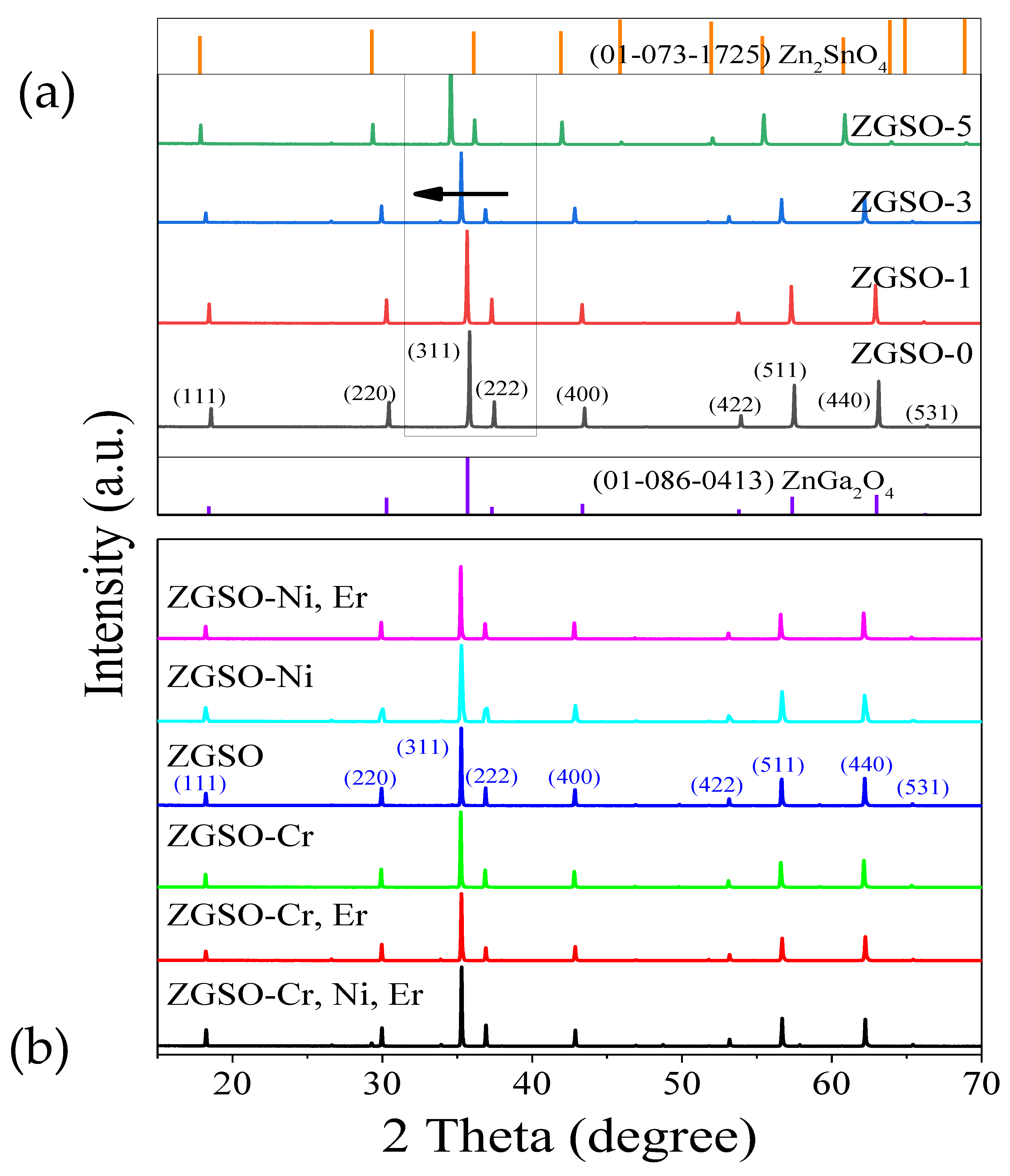
A normal spinel (ZGO) and an inverse spinel (ZSO), in addition to a series of complex spinel nanomaterials, were designed as combinations of the normal spinel ZnGa2O4 and inverse spinel Zn2SnO4 with different Sn amounts, as represented by the formula Zn1+xGa2−2xSnxO4, x = 0, 0.1, 0.2, 0.3, …, 0.6, denoted as ZGSO (from ZGSO-0 to ZGSO-6, respectively). The content of Ni2+-doped ZGSO NPs can be seen in Table S1 and Figure S6 in the Supplementary Materials. The most favorable persistent luminescence properties suggested a nominal doping content for the activator Ni2+ at 0.5 mol % in respect to Ga3+ ions in the matrix; this will be discussed in detail in the following sections of the paper. Divalent nickel ions as dopants in this host are in the octahedral site, as the stabilization energy is fairly important (greater than 80 kJ.mol−1) [37]. Therefore, only the octahedral sites are populated with Ni2+ ions as dopants. Furthermore, one should notice the very similar ionic radius of Ni2+ with Ga3+ cations in addition to the strong octahedral coordination preference [38]. In addition, other contents of doping cations (Ni2+, Er3+, and Cr3+) in ZGSO-3 NPs are shown in Tables S2 and S3, and Figure S10. Thermoluminescence spectra of Ni2+ in ZGO and ZGSO matrices have also been obtained; these are shown in Figure S11. As previously observed for ZGSO:Cr [34], the TL glow presents shallower traps when Sn4+ is introduced with an increase in signal (see the signal-over-noise ratio) and the resulting broadening.
3.1. Crystal Structure Analysis by Powder X-ray Diffraction (PXRD)
The ionic radius of Sn4+ is 0.83 Å, which is slightly greater than that of Ga3+ (0.76 Å). Thus, the Sn4+ ion is well adapted to an octahedral configuration with Sn–O distances (2.05 Å), which is similar to the Ga–O distances (1.98 Å). Sn4+ ions can be introduced into the ZnGa2O4 host [34] without affecting its structural properties. As shown in Figure 1a, the diffraction peaks (at 2θ = 18.4°, 30.3°, 35.7°, 57.4°, 63.0°) of sample ZGSO-0 (Sn free, normal ZGO) relate well to the standard lattice planes [(111), (220), (311), (511), (440), respectively] of ZnGa2O4 (JCPDS No. 01-086-0413). For the series of Zn1+xGa2−2xSnxO4 materials with increasing x values (concentration of Sn), the PXRD patterns show a slight shift in the diffraction peaks, as seen in Figure 1. The diffraction peaks shift to lower 2θ values with an increase in Sn4+/Ga3+ ratio. A comparison of the ZGSO-2 (x = 2) and ZGSO-4 (x = 4) patterns is shown in Figure S1.
The Ni2+ cation crystal field could be modified by tuning the Sn4+/Ga3+ ratios, as seen in the following section of the paper. This is also the case for the introduction of Cr3+, as previously reported [35]. In contrast, any shift in the position of the diffraction peaks is observed with a 0.5% Ni2+ doping ratio (Figure 1b). Ni2+, Cr3+, and to a lesser extent Er3+, as the coordination is less favorable, are cations that can be incorporated effectively (up to 1 or 2%, as shown previously) into octahedral lattice sites, due to a similar ionic radius and valence with Ga3+ cations [39]. Hence, as it has been suggested that multi-emission is effectively covered in the range from visible to NIR-III, low doping ratios of Er3+ (1%) and Ni2+ (0.5%) or Cr3+ (0.5%) have been introduced into hosts without concern for the stability of the crystal structure and while retaining the normal spinel structure of ZnGa2O4 in all samples regardless of the tested Sn4+ contents, as seen in Figure 1.
3.2. Absorption Spectra Analysis
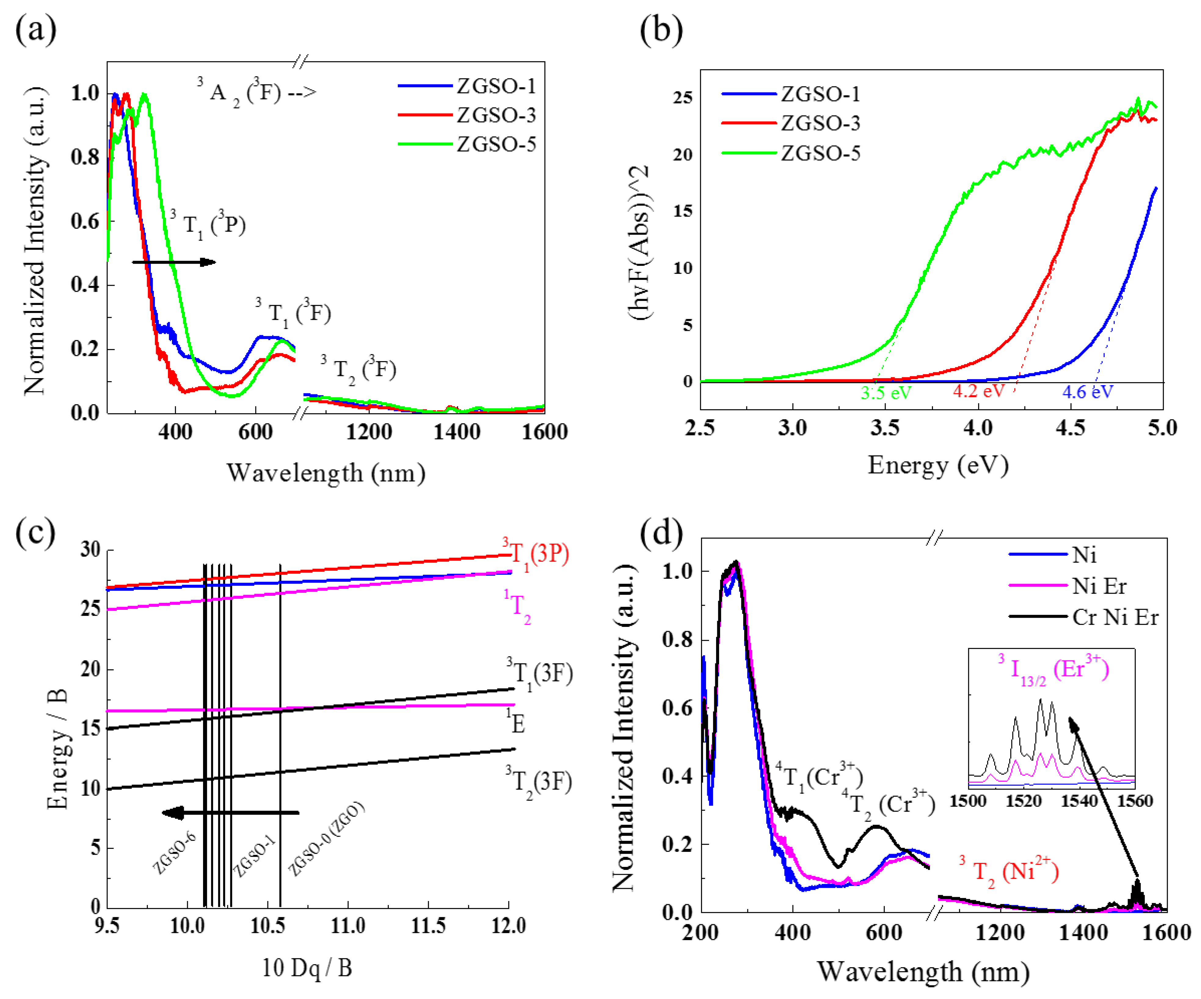
The absorption spectra of the samples were recorded to further validate the relationship between the change in crystal structure and the energy difference between electronic transitions. ZGSO-1, ZGSO-3, and ZGSO-5 are shown in Figure 2a. Figure S2 in the supplementary materials shows the normalized absorption spectra of Ni2+-doped ZGSO-2 and ZGSO-4. Strong, broad excitation bands located between ~260 nm and ~320 nm are observed. For example, in the ZGSO-3: Ni sample, the observed shoulders at around 370 nm are attributed to the 3A2 (3F) → 3T1 (3P) spin-allowed transition of Ni2+, almost overlapping with the bandgap edge of the ZGSO matrix. This bandgap absorption edge originates from the O–Ga charge-transfer transition in the ZGSO host, which is also seen in Figure 2b, and the bandgap values decrease with Sn4+ content. The bandgap energy values can be extracted and calculated using the Kubelka–Munk function [35]. With an increase in Sn4+ content in the ZGSO matrix, the bandgap values varied from 3.5 to 4.6 eV using the following formula:
where E is the bandgap energy (in eV) and λ is the experimental absorption wavelength, as shown in Figure 2.
In addition, the d8 Tanabe–Sugano diagrams shown in Figure 2c and Figure S3 (in the Supplementary Materials) effectively show that the shifted absorption peaks of Ni2+ towards a longer wavelength depend on an increase in the Sn4+/Ga3+ ratio corresponding to a decrease in crystal field strength [40]. Two absorption peaks of ZGSO-3: Ni2+ observed at ~600 nm and ~1050 nm originate from the 3A2 (3F) → 3T1 (3F) and 3A2 (3F) → 3T2 (3F) transitions of Ni2+, respectively. For a more quantitative analysis, the crystal field strength value Dq and the Racah parameter B can be estimated using the energies of various absorption peaks as follows [29]:
where and are the energies corresponding to Ni2+ ions [3A2 (3F) → 3T1(3P)] and [3A2 (3F) → 3T2 (3F)] transitions, respectively.
As a result, variation in the crystal field strength of ZGSO was observed. As Sn4+ content varied from 0.1 to 0.3, and even up to 0.5, the energy level of the divalent nickel corresponded to lower crystal field strength values (10 Dq decreased from 10.58 to 10.12). Crystal field values, (10 Dq/B), in addition to other related parameters, are shown in Table 1.
Furthermore, Er3+ and Cr3+ ions were used as dopants to obtain other emission wavelengths. The absorption spectra of Er3+ and Er3+/Cr3+ co-doped ZGSO: Ni2+ NPs are shown in Figure 2d. The absorption peak at 1530 nm is attributed to the Er3+ 4I15/2 → 4I13/2 transition. The broad absorption bands at 410 nm and 570 nm are attributed to the 4A2 (4F) →4T1 (4F) and 4A2 (4F) → 4T2 (4F) transitions of Cr3+, respectively.
3.3. Photoluminescence (PL) Spectral Analysis
Using a control of tin composition, a tunable 3T2 (3F) → 3A2 (3F) transition of Ni2+ PL extends from 1270 to 1340 nm, as shown in Figure 3a. The variation in wavelength is also effectively explained in the Tanabe–Sugano diagram d8 in Figure 2d.
As co-dopants, Er3+ cations with several emissions in the visible, NIR-I, and even SWIR range may be very interesting, and we have focused our attention on the ZGSO-3: Ni2+, Er3+ sample, which presents the most favorable persistent luminescence properties, as shown in the following section. As shown in Figure 3b, ZGSO-3: Ni2+, Er3+ NPs show PL peaks at 980 nm (NIR-I range) and 1300 nm and 1533 nm (NIR-II range) under 365 nm irradiation. The peak at 1300 nm is attributed to the 3T2 (3F) → 3A2 (3F) transition of octahedral Ni2+ ions [41].
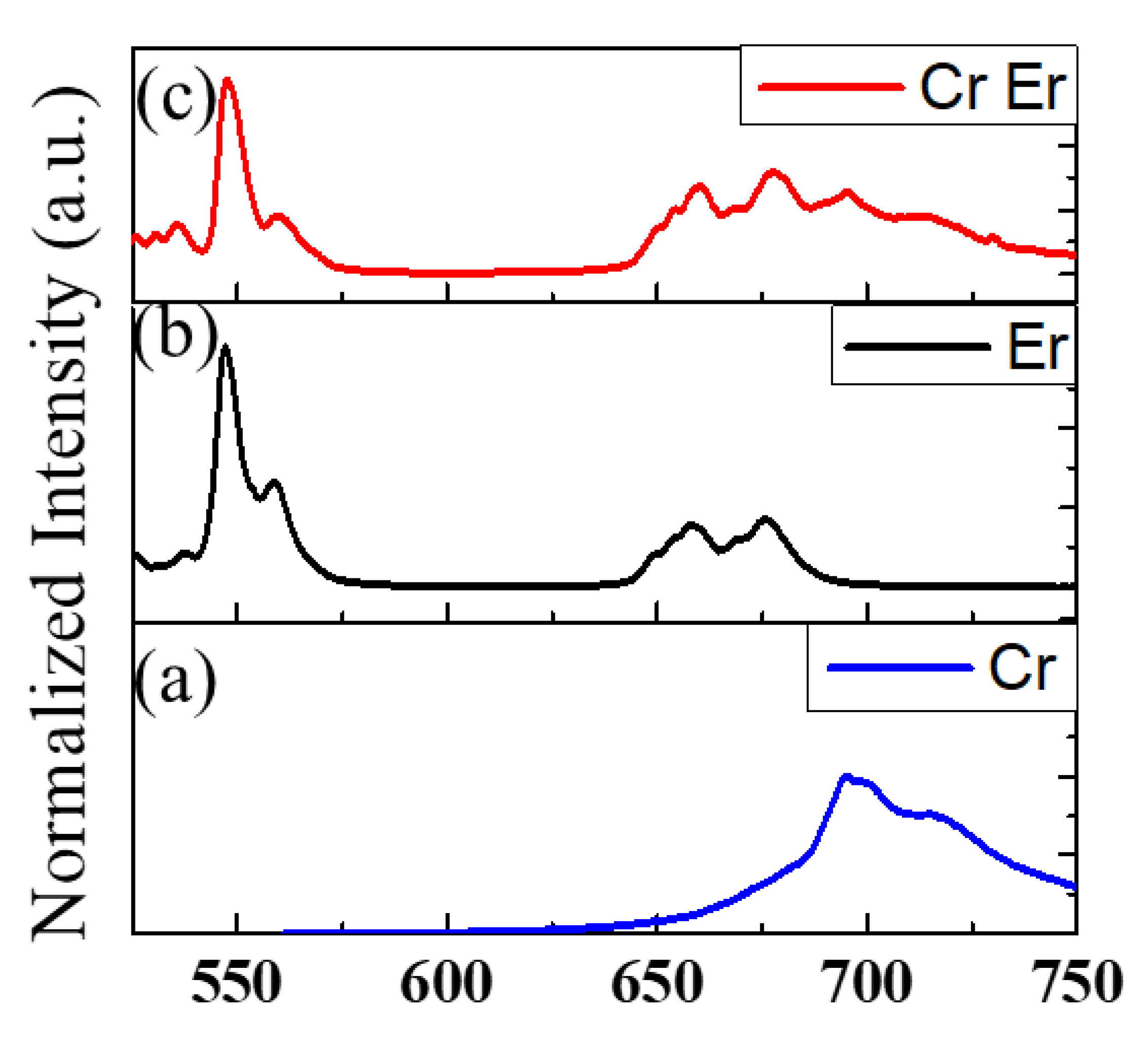
On the other hand, Er3+ is responsible for the emission at 980 nm (NIR-I) and 1533 nm (NIR-II), attributed to the 4I11/2 → 4I15/2 and 4I13/2 → 4I15/2 transitions, respectively, as shown in Figure S4c. These optical properties—with emission in the visible, deep-red, and NIR ranges—have been obtained due to knowledge within our laboratories, which have been working on the zinc gallate matrix for several years [42,43,44,45,46,47]. The PL spectra of (a) ZGSO:Cr3+, (b) ZGSO:Er3+, and (c) ZGSO:Cr3+, Er3+ in the visible range are shown in Figure 4. ZGSO-3: Ni2+, Er3+, Cr3+ NPs were also considered within this work because Cr3+ provides a 700 nm persistent luminescence in the deep-red (or NIR-I) range [46,47]. Under 365 nm UV excitation, the multi-emission on the PL spectrum of ZGSO-3: Ni2+, Er3+, Cr3+ NPs covers visible, NIR-I, NIR-II, and NIR-III ranges; the PL features will be compared to the persistent luminescence properties in the following section of the paper.
3.4. Persistent Luminescence Spectral Analysis
After UV excitation removal, a persistent luminescence signal is observed for all Ni2+-doped ZGSO NPs. This persistent luminescence is assigned to the 3T2 (3F) → 3A2 (3F) transition of octahedral Ni2+ cations [42]. The position of the broad emission peak of Ni2+ shifts from 1270 to 1340 nm by increasing the Sn (x value, Table S1) content in the matrix (see Figure 5a), due to a decrease in the strength of the crystal field. Figure S4 shows a possible mechanism to explain the persistent luminescence signal for ZGSO-3: Ni2+ NPs. Under UV excitation, charges are formed and trapped in the ZGSO host defects. Based on this system, the release with temperature of the trapped charges after excitation removal and recombination toward the Ni2+ centers lead to the persistent luminescence signal in the SWIR range, attributed to the 3T2 (3F) → 3A2 (3F) transition (Figure S4b). An increase in Zn2+ and Sn4+ content leads to a decrease in crystal field around Ni2+, similar to that seen with photoluminescence, and a shift in the persistent luminescence signal towards a longer wavelength (i.e., lower energy) is observed, as seen in Figure 5a.
Although all samples show a rapid decrease in persistent luminescence, the initial intensity depends on the sample. For example, as shown in Figure 5b, of ZGSO-1:Ni2+, ZGSO-3:Ni2+, and ZGSO-5:Ni2+, ZGSO-3:Ni2+ (namely, Zn1.3Ga1.4Sn0.3O4::0.5%Ni2+) shows the highest initial intensity value of persistent luminescence at 1300 nm, as shown in Figure S5. Furthermore, the Ni2+ doping concentration was optimized (Figure S6) and was revealed to be 0.5%; in comparison, the persistent luminescence intensity of the Ni2+-doped ZGSO-3 samples with different nickel concentrations was 0.25%, 0.5%, and 1%, as shown in Figure S6. As a result, the persistent luminescence at 1300 nm increased as the crystal field value (10 Dq/B) decreased to 10.20 from an initial value of 10.58. Zn1.3Ga1.4Sn0.3O4::0.5%Ni2+ is the optimal material as it has the strongest persistent luminescence intensity of all the samples prepared and reported in Table S1.
The effect of the amount of Er3+ in the ZGSO matrix was also evaluated. As shown in Figure S10, of the different concentrations tested, the optimal amount of Er3+ is 1% atomic. On the other hand, the inset in Figure 5b shows the time dependence of the NIR persistent luminescence with wavelengths at 1300 nm and 1530 nm from Er3+, Ni2+ co-doped ZGSO-3 NPs. While the persistent luminescence intensity at 1300 nm reduced slowly, the emission at 1530 nm (see Figure 3b) fully disappeared when the excitation was removed, and no persistent emission could be recorded. For the ZGSO:Cr3+, Er3+ samples, the visible persistent emissions in the red and deep-red ranges are shown in Figure S7. Persistent luminescence spectra of ZGSO:Cr3+ and ZGSO:Cr3+, Er3+ are similar, and no red emission is observed (at 650 nm for Er3+ cations); the persistent luminescence under UV excitation is governed solely by Cr3+ decay. Meanwhile, Figure S4 shows schematic diagrams of the absorption/emission bands; trapping/detrapping and energy-transfer mechanisms lead to deep-red emissions of (a) ZGSO-3:Cr3+ NPs, NIR emission of (b) ZGSO-3:Ni2+ NPs, and 4f-4f transition of (c) ZGSO-3:Er3+ NPs.
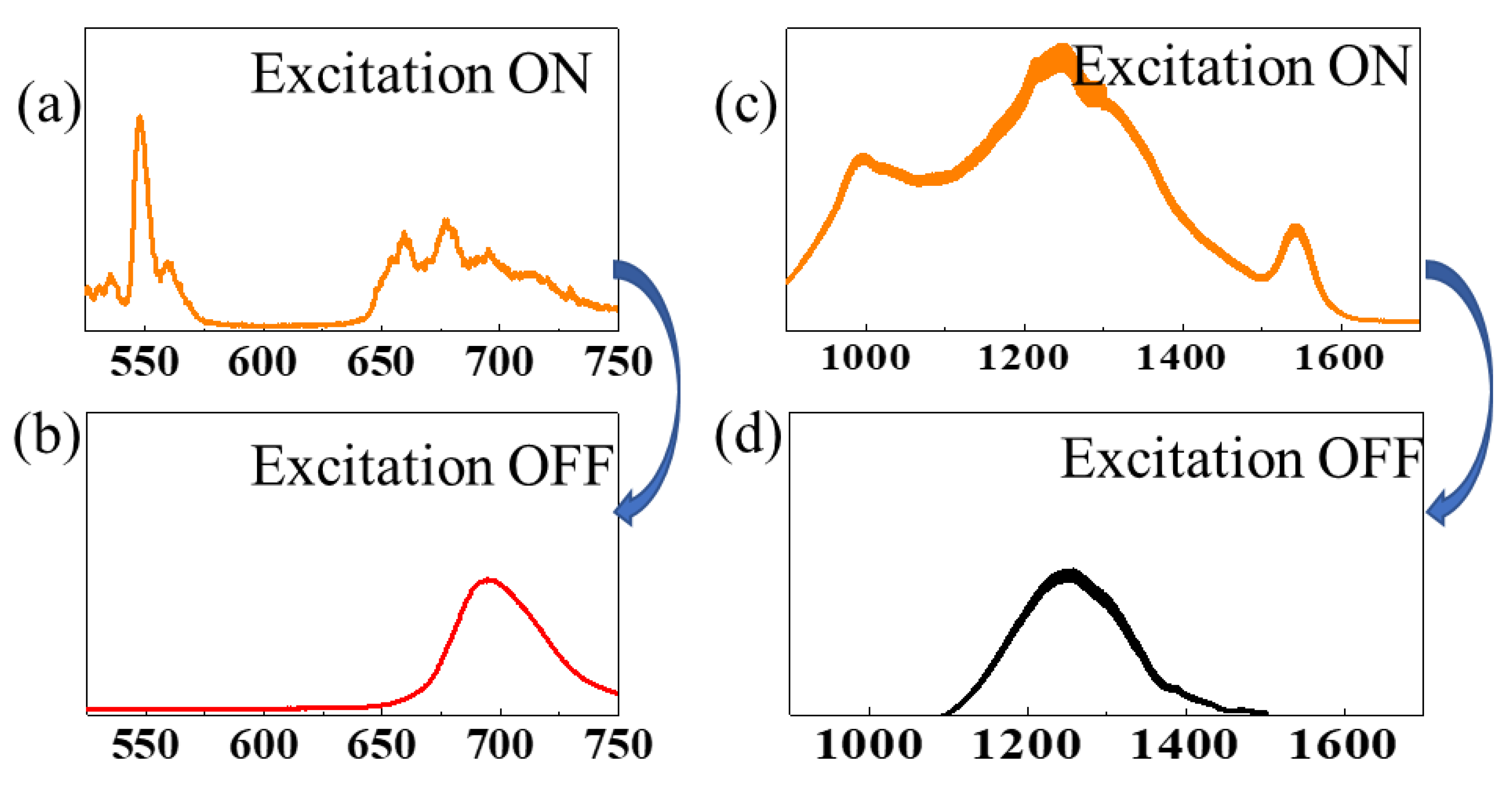
The spectra in Figure 6 indicate the PL (Figure 6a) and persistent luminescence (Figure 6b) of ZGSO:Ni3+, Cr3+, Er3+, detected with an Si-based detector. In the SWIR (from NIR-II to NIR-III) range; Figure 6c,d also provide the spectrum of PL (Figure 6c) and persistent luminescence (Figure 6c) of the same sample ZGSO:Ni2+, Cr3+, Er3+, detected with an InGaAs-based detector. Peaks of Er3+ vanished at ~550 nm and ~660 nm in the visible range and at ~980 nm and ~1530 nm in the NIR, corresponding to a lack of Er3+ remaining in the samples. With these features of PL and persistent luminescence, anti-counterfeiting applications have been proposed.
3.5. Towards Anti-Counterfeiting Applications
3.5.1. A Two-Step Anti-Counterfeiting Method in the NIR-II Range
A new two-step anti-counterfeiting method in the NIR range based on ZGSO:Ni2+, Er3+ NPs is introduced. As described above, NIR multi-emissions of PL at ~980 nm, ~1300 nm, and ~1530 nm are obtained from NPs under UV irradiation as a first security step (for bright emissions, UV excitation wavelengths should be in the range 275–400 nm). As shown by the example image, the “UTCBS” acronym noted by ZGSO:Ni2+, Er3+ NPs can be easily detected due to their strong PL (Figure 7a), corresponding to the PL in the NIR range.
For a second security step, after removing UV excitation, the persistent luminescence pattern “UTCBS” is obtained with an InGaAs-based camera for at least 15 min (Figure 7b). Additionally, another security step could be observation of the change in signal shape between PL and persistent luminescence (see Figure 3b). The Er3+ emission in the SWIR vanishes in the persistent luminescence spectrum, which provides a new step in the field of anti-counterfeiting, NIR (or SWIR) emission giving higher accuracy and security. In addition, the PL of the pattern “UTCBS” noted by ZGSO:Ni2+, Er3+ NPs excited by the 980 nm and 808 nm NIR lasers, respectively, in the Er3+ absorption bands is shown in Figure 7. No persistent luminescence was observed under these NIR excitation wavelengths.
3.5.2. Multi-Level Anti-Counterfeiting Method in Visible, NIR-I, and NIR-II Ranges
To advance this proof of concept using Zn1.3Ga1.4Sn0.3O4 material, we have shown that we can introduce several dopants to propose a multi-level anti-counterfeiting compound in the visible and NIR ranges. (i) First, this work benefits from stable NIR-II photoluminescence from Er3+ and NIR-II persistent luminescence from Ni2+, in addition to NIR-I persistent emission when doping with Cr3+ (Figure 4 and Figure 6). (ii) Second, for further certification requirements, information and images could be read in both the visible and NIR ranges. To further address the advantages of anti-counterfeiting by this type of novel NP, patterns based on ZGSO:Ni2+, Er3+, Cr3+ NPs were evaluated by both Si-based and InGaAs-based cameras. A multi-level anti-counterfeiting system could then be obtained, as follows:
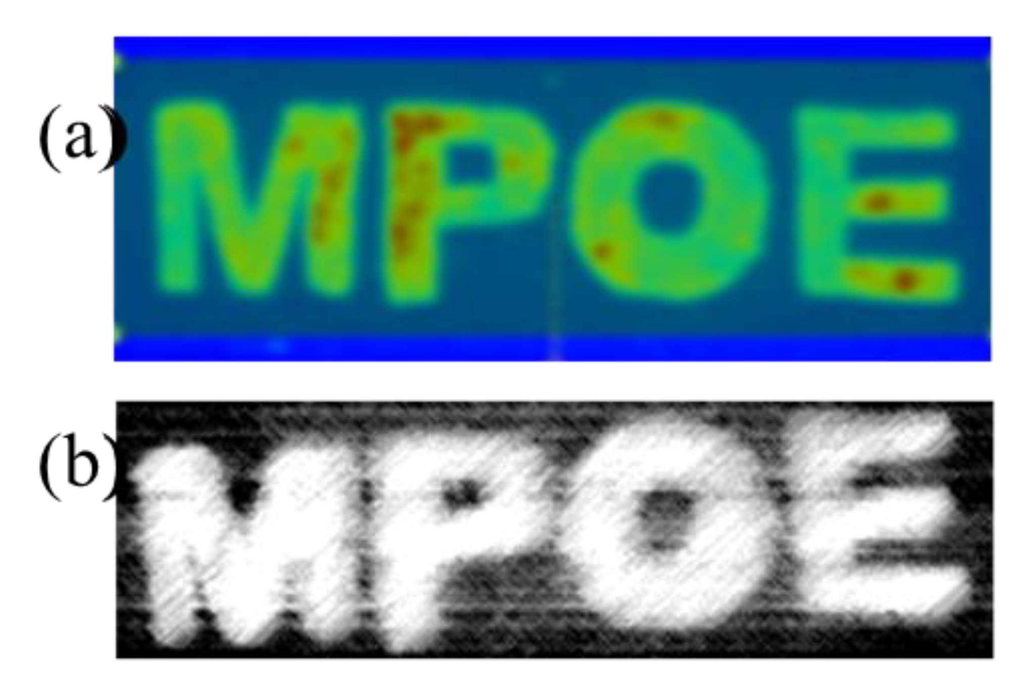
The changes in spectra obtained by optical spectroscopy (shown in Figure 6) are also observed in the images under both Si-based and InGaAs-based cameras. For example, the “MPOE” pattern was hand painted using ZGSO:Ni2+, Er3+, Cr3+ NPs. Figure 8 shows (a) an NIR-I persistent luminescence image from an “MPOE” pattern detected with a Si-based visible camera and (b) an NIR-II persistent luminescence image from an “MPOE” pattern detected with an InGaAs-based NIR camera after UV excitation removal. Figure S9 shows (a) the “MPOE” pattern template for hand painting, using ZGSO-3:Ni2+, Er3+, Cr3+ NPs and (b) an NIR-II PL image from the “MPOE” pattern under UV excitation, detected with an InGaAs-based NIR camera with minimum contrast to avoid saturation. In comparison with the NIR-II PL image, the persistent luminescence signal takes advantage of avoidance of an autofluorescence background and provision of an enhanced anti-counterfeiting effect.
4. Conclusions
We successfully prepared several transition-metal (Ni2+ and/or Cr3+) cations and rare-earth (Er3+) co-doped ZGSO spinel nanocrystals with controllable photoluminescence wavelengths by tuning the concentration of Sn4+ and intensity emission and persistent luminescence for chromium and nickel transition-metal cations. Of these, multi-emission of PL in the NIR range benefits from the Er3+ ions working as emitters in nanoparticles of Zn1.3Ga1.4Sn0.3O4 co-doped with Ni2+, Er3+, and Cr3+ cations. Furthermore, Zn1.3Ga1.4Sn0.3O4 NPs exhibit persistent luminescence at 700 nm in the NIR-I range and 1300 nm NIR-II range, and their decay can last for more than 5 min after excitation removal.
A multi-level anti-counterfeiting pattern was designed by recording PL and persistent luminescence in the red, deep-red, and SWIR ranges. To further improve security, alternative excitation sources could be envisioned in the future due to the very wide excitation ranges of persistent luminescence materials [48,49,50,51,52].
Supplementary Materials
The following supporting information can be downloaded at https://www.mdpi.com/article/10.3390/ma16031132/s1: Table S1: Names and formulae of the Ni2+-doped ZGSO samples; Table S2: Names and formulae of the co-doped ZGSO samples; Table S3: Names and formulae of the Cr3+-doped ZGSO samples; Figure S1: XRD patterns of 0.5% Ni2+-doped ZGSO-2, ZGSO-4, and ZSO samples; Figure S2: Normalized absorption spectra of 0.5% Ni2+-doped ZGSO-2 and ZGSO-4 samples; Figure S3: Tanabe–Sugano diagram of Ni2+ (d8 configuration) in the complex spinel samples of ZGSO-0 (ZnGa2O4:0.5%Ni2+) and ZGSO-6 (Zn1.6Ga0.8Sn0.6O4:0.5%Ni2+) corresponding to different Sn4+ concentrations; Figure S4: Schematic diagram of the absorption/emission bands; trapping/detrapping and energy-transfer mechanisms leading to deep-red emission of (a) ZGSO-3:Cr3+ NPs, and NIR emission of (b) ZGSO-3:Ni2+ NPs, and 4f-4f transition of (c) ZGSO-3:Er3+ NPs; Figure S5: Persistent luminescence intensity of Ni2+-doped ZGSO-0–ZGSO-6 samples (detection 1 min after cutting off the 365 nm UV lamp excitation). Same quantity of powder and same excitation time is used for all samples. Detection with InGaAs camera; Figure S6: Persistent luminescence intensity of the Ni2+-doped ZGSO-3 for three nominal different doping concentrations, namely 0.25%, 0.5% and 1% (detection with the InGaAs camera, 1 min after cutting off the 365 nm UV lamp excitation); Figure S7: Persistent luminescence spectra of (a) ZGSO-3:Cr3+ and (b) ZGSO-3:Er3+, Cr3+, respectively (detection with the Si camera 1 min after removal of UV lamp excitation (365 nm, 5 min)); Figure S8: NP size measurement of ZGSO-3:Ni2+ NPs and ZGSO-3:Ni2+, Er3+, Cr3+ NPs obtained by DLS; Figure S9: (a) Image of the “MPOE” pattern template for hand painting with ZGSO-3:Ni2+, Er3+, Cr3+ NPs. (b) PL image came from the “MPOE” pattern hand printed using ZGSO-3: Ni2+, Er3+, Cr3+ NPs under UV excitation, detected with InGaAs-based NIR camera with minimum contrast to avoid saturation.
Author Contributions
Conceptualization, G.C.; methodology, B.V.; software, C.R.; validation, T.D.; data curation and writing—original draft preparation, G.C.; writing—review and editing, T.D., C.R. and B.V.; supervision, C.R. and B.V. All authors have read and agreed to the published version of the manuscript.
Funding
This research was funded by Agence Nationale de la Recherche (ANR-18-CE08-0012 PERSIST) and the CSC Grant program.
Institutional Review Board Statement
Not applicable.
Informed Consent Statement
Not applicable.
Data Availability Statement
The data presented in this study are available on request from the corresponding author.
Acknowledgments
The authors would like to thank the Agence Nationale de la Recherche (ANR-18-CE08-0012 PERSIST) and the CSC Grant program.
Conflicts of Interest
The funders had no role in the design of the study; in the collection, analyses, or interpretation of data; in the writing of the manuscript; or in the decision to publish the results.
References
- De Guzman, G.N.A.; Fang, M.H.; Liang, C.H.; Bao, Z.; Hu, S.F.; Liu, R.S. Near-infrared phosphors and their full potential: A review on practical applications and future perspectives. J. Lumin. 2020, 219. [Google Scholar] [CrossRef]
- Liu, J.; Lecuyer, T.; Seguin, J.; Mignet, N.; Scherman, D.; Viana, B.; Richard, C. Imaging and therapeutic applications of persistent luminescence nanomaterials. Adv. Drug Deliv. Rev. 2019, 138, 193–210. [Google Scholar] [CrossRef] [PubMed]
- Bessière, A.; Lecointre, A.; Benhamou, R.A.; Suard, E.; Wallez, G.; Viana, B. How to induce red persistent luminescence in biocompatible Ca3(PO4)2. J. Mater. Chem. C 2013, 1, 1252–1259. [Google Scholar] [CrossRef]
- Sun, Z.Y.; Yang, J.X.; Huai, L.W.; Wang, W.X.; Ma, Z.D.; Sang, J.K.; Zhang, J.C.; Li, H.H.; Ci, Z.P.; Wang, Y.H. Spy Must Be Spotted: A Multistimuli-Responsive Luminescent Material for Dynamic Multimodal Anticounterfeiting and Encryption. Acs Appl. Mater. Interfaces 2018, 10, 21451–21457. [Google Scholar] [CrossRef] [PubMed]
- Lei, L.; Chen, D.Q.; Li, C.; Huang, F.; Zhang, J.J.; Xu, S.Q. Inverse thermal quenching effect in lanthanide-doped upconversion nanocrystals for anti-counterfeiting. J. Mater. Chem. C 2018, 6, 5427–5433. [Google Scholar] [CrossRef]
- Liu, J.; Rijckaert, H.; Zeng, M.; Haustraete, K.; Laforce, B.; Vincze, L.; Van Driessche, I.; Kaczmarek, A.M.; Van Deun, R. Simultaneously excited downshifting/upconversion luminescence from lanthanide-doped core/shell fluoride nanoparticles for multimode anticounterfeiting. Adv. Funct. Mater. 2018, 28, 1707365. [Google Scholar] [CrossRef]
- Suo, H.; Zhu, Q.; Zhang, X.; Chen, B.; Chen, J.; Wang, F. High-security anti-counterfeiting through upconversion luminescence. Mater. Today Phys. 2021, 21, 100520. [Google Scholar] [CrossRef]
- Zhang, Z.; Ma, N.; Kang, X.; Li, X.; Yao, S.; Han, W.; Chang, H. Switchable up and down-conversion luminescent properties of Nd (III)-nanopaper for visible and near-infrared anti-counterfeiting. Carbohydr. Polym. 2021, 252, 117134. [Google Scholar] [CrossRef]
- Zhang, Z.; Chang, H.; Xue, B.; Zhang, S.; Li, X.; Wong, W.-K.; Li, K.; Zhu, X. Near-infrared and visible dual emissive transparent nanopaper based on Yb (III)–carbon quantum dots grafted oxidized nanofibrillated cellulose for anti-counterfeiting applications. Cellulose 2018, 25, 377–389. [Google Scholar] [CrossRef]
- Wang, X.; Li, T.; Liang, W.; Zhu, C.; Guo, L. Triple NIR light excited up-conversion luminescence in lanthanide-doped BaTiO3 phosphors for anti-counterfeiting. J. Am. Ceram. Soc. 2021, 104, 5826–5836. [Google Scholar] [CrossRef]
- Zhou, S.; Wang, Y.; Hu, P.; Zhong, W.; Jia, H.; Qiu, J.; Fu, J. Cascaded Photon Confinement-Mediated Orthogonal RGB-Switchable NaErF4-Cored Upconversion Nanoarchitectures for Logicalized Information Encryption and Multimodal Luminescent Anti-Counterfeiting. Laser Photonics Rev. 2022, 2200531. [Google Scholar] [CrossRef]
- Lecuyer, T.; Durand, M.A.; Volatron, J.; Desmau, M.; Lai-Kuen, R.; Corvis, Y.; Seguin, J.; Wang, G.; Alloyeau, D.; Scherman, D.; et al. Degradation of ZnGa2O4:Cr3+ luminescent nanoparticles in lysosomal-like medium. Nanoscale 2020, 12, 1967–1974. [Google Scholar] [CrossRef] [PubMed]
- Liu, F.Y.; Zhao, Q.; You, H.P.; Wang, Z.X. Synthesis of stable carboxy-terminated NaYF4:Yb3+, Er3+@SiO2 nanoparticles with ultrathin shell for biolabeling applications. Nanoscale 2013, 5, 1047–1053. [Google Scholar] [CrossRef] [PubMed]
- Ma, C.Q.; Liu, H.H.; Ren, F.; Liu, Z.; Sun, Q.; Zhao, C.J.; Li, Z. The Second Near-Infrared Window Persistent Luminescence for Anti-Counterfeiting Application. Cryst. Growth Des. 2020, 20, 1859–1867. [Google Scholar] [CrossRef]
- Hong, G.S.; Antaris, A.L.; Dai, H.J. Near-infrared fluorophores for biomedical imaging. Nat. Biomed. Eng. 2017, 1. [Google Scholar] [CrossRef]
- Yang, J.; Zhou, Y.; Ming, H.; Song, E.; Zhang, Q. Site-Selective Occupancy of Mn2+ Enabling Adjustable Red/Near-Infrared Multimode Luminescence in Olivine for Dynamic Anticounterfeiting and Encryption. ACS Appl. Electron. Mater. 2022, 4, 831–841. [Google Scholar] [CrossRef]
- Gao, G.; Busko, D.; Joseph, R.; Howard, I.A.; Turshatov, A.; Richards, B.S. Highly efficient La2O3: Yb3+, Tm3+ single-band NIR-to-NIR upconverting microcrystals for anti-counterfeiting applications. ACS Appl. Mater. Interfaces 2018, 10, 39851–39859. [Google Scholar] [CrossRef]
- Zhang, Y.; Huang, R.; Li, H.; Lin, Z.; Hou, D.; Guo, Y.; Song, J.; Song, C.; Lin, Z.; Zhang, W. Triple-Mode Emissions with Invisible Near-Infrared After-Glow from Cr3+-Doped Zinc Aluminum Germanium Nanoparticles for Advanced Anti-Counterfeiting Applications. Small 2020, 16, 2003121. [Google Scholar] [CrossRef]
- Kang, H.; Lee, J.W.; Nam, Y. Inkjet-printed multiwavelength thermoplasmonic images for anticounterfeiting applications. ACS Appl. Mater. Interfaces 2018, 10, 6764–6771. [Google Scholar] [CrossRef]
- Yu, X.; Zhang, H.; Yu, J. Luminescence anti-counterfeiting: From elementary to advanced. Aggregate 2021, 2, 20–34. [Google Scholar] [CrossRef]
- Zhu, S.J.; Herraiz, S.; Yue, J.Y.; Zhang, M.X.; Wan, H.; Yang, Q.L.; Ma, Z.R.; Wang, Y.; He, J.H.; Antaris, A.L.; et al. 3D NIR-II Molecular Imaging Distinguishes Targeted Organs with High-Performance NIR-II Bioconjugates. Adv. Mater. 2018, 30, 1705799. [Google Scholar] [CrossRef] [PubMed] [Green Version]
- Przybylska, D.; Grzyb, T.; Erdman, A.; Olejnik, K.; Szczeszak, A. Anti-counterfeiting system based on luminescent varnish enriched by NIR-excited nanoparticles for paper security. Sci. Rep. 2022, 12, 19388. [Google Scholar] [CrossRef] [PubMed]
- Antaris, A.L.; Chen, H.; Cheng, K.; Sun, Y.; Hong, G.S.; Qu, C.R.; Diao, S.; Deng, Z.X.; Hu, X.M.; Zhang, B.; et al. A small-molecule dye for NIR-II imaging. Nat. Mater. 2016, 15, 235–242. [Google Scholar] [CrossRef] [PubMed]
- Chan, M.H.; Huang, W.T.; Chen, K.C.; Su, T.Y.; Chan, Y.C.; Hsiao, M.; Liu, R.S. The optical research progress of nanophosphors composed of transition elements in the fourth period of near-infrared windows I and II for deep-tissue theranostics. Nanoscale 2022, 14, 7123–7136. [Google Scholar] [CrossRef]
- Sordillo, L.A.; Pu, Y.; Pratavieira, S.; Budansky, Y.; Alfano, R.R. Deep optical imaging of tissue using the second and third near-infrared spectral windows. J. Biomed. Opt. 2014, 19, 056004. [Google Scholar] [CrossRef]
- Xu, J.; Tanabe, S.; Sontakke, A.D.; Ueda, J. Near-infrared multi-wavelengths long persistent luminescence of Nd3+ ion through persistent energy transfer in Ce3+, Cr3+ co-doped Y3Al2Ga3O12 for the first and second bio-imaging windows. Appl. Phys. Lett. 2015, 107. [Google Scholar] [CrossRef] [Green Version]
- Xu, J.; Murata, D.; Katayama, Y.; Ueda, J.; Tanabe, S. Cr3+/Er3+ co-doped LaAlO3 perovskite phosphor: A near-infrared persistent luminescence probe covering the first and third biological windows. J. Mater. Chem. B 2017, 5, 6385–6393. [Google Scholar] [CrossRef] [PubMed]
- Xu, J.; Murata, D.; Ueda, J.; Tanabe, S. 1.5 um persistent luminescence of Er3+ in Gd3Al5-xGaxO12 (GAGG) garnets via persistent energy transfer. In Proceedings of the Conference on Optical Components and Materials XVI, San Francisco, CA, USA, 4–6 February 2019. [Google Scholar]
- Abdukayum, A.; Chen, J.T.; Zhao, Q.; Yan, X.P. Functional Near Infrared-Emitting Cr3+/Pr3+ Co-Doped Zinc Gallogermanate Persistent Luminescent Nanoparticles with Superlong Afterglow for in Vivo Targeted Bioimaging. J. Am. Chem. Soc. 2013, 135, 14125–14133. [Google Scholar] [CrossRef]
- Gong, Z.; Liu, Y.X.; Yang, J.; Yan, D.T.; Zhu, H.C.; Liu, C.G.; Xu, C.S.; Zhang, H. A Pr3+ doping strategy for simultaneously optimizing the size and near infrared persistent luminescence of ZGGO:Cr3+ nanoparticles for potential bio-imaging. Phys. Chem. Chem. Phys. 2017, 19, 24513–24521. [Google Scholar] [CrossRef]
- Castaing, V.; Sontakke, A.D.; Carrion, A.J.F.; Allix, M.; Viana, B. Deep Red and Near Infrared Persistent Luminescence in Yb3+,Cr3+ co-Doped ZnGa2O4 Nano Glass Ceramics. In Proceedings of the Conference on Lasers and Electro-Optics Europe/European Quantum Electronics Conference (CLEO/Europe-EQEC), Munich, Germany, 23–27 June 2019. [Google Scholar]
- Glais, E.; Pellerin, M.; Castaing, V.; Alloyeau, D.; Touati, N.; Viana, B.; Chaneac, C. Luminescence properties of ZnGa2O4:Cr3+,Bi3+ nanophosphors for thermometry applications. Rsc Adv. 2018, 8, 41767–41774. [Google Scholar] [CrossRef]
- Castaing, V.; Sontakke, A.D.; Xu, J.; Fernandez-Carrion, A.J.; Genevois, C.; Tanabe, S.; Allix, M.; Viana, B. Persistent energy transfer in ZGO:Cr3+,Yb3+: A new strategy to design nano glass-ceramics featuring deep red and near infrared persistent luminescence. Phys. Chem. Chem. Phys. 2019, 21, 19458–19468. [Google Scholar] [CrossRef] [PubMed]
- Pan, Z.F.; Castaing, V.; Yan, L.P.; Zhang, L.L.; Zhang, C.; Shao, K.; Zheng, Y.F.; Duan, C.K.; Liu, J.H.; Richard, C.; et al. Facilitating Low-Energy Activation in the Near-Infrared Persistent Luminescent Phosphor Zn1+xGa2−2xSnxO4:Cr3+ via Crystal Field Strength Modulations. J. Phys. Chem. C 2020, 124, 8347–8358. [Google Scholar] [CrossRef]
- Nie, J.M.; Li, Y.; Liu, S.S.; Chen, Q.Q.; Xu, Q.; Qiu, J.R. Tunable long persistent luminescence in the second near-infrared window via crystal field control. Sci. Rep. 2017, 7, 12392. [Google Scholar] [CrossRef] [Green Version]
- Bessiere, A.; Jacquart, S.; Priolkar, K.; Lecointre, A.; Viana, B.; Gourier, D. ZnGa2O4:Cr3+: A new red long-lasting phosphor with high brightness. Opt. Express 2011, 19, 10131–10137. [Google Scholar] [CrossRef] [PubMed]
- Pellerin, M.; Castaing, V.; Gourier, D.; Chaneac, C.; Viana, B. Persistent luminescence of transition metal (Co, Ni center dot center dot center dot)-doped ZnGa2O4 phosphors for applications in the near-infrared range. In Proceedings of the Conference on Oxide-Based Materials and Devices IX, San Francisco, CA, USA, 28 January–1 February 2018. [Google Scholar]
- Bessiere, A.; Sharma, S.K.; Basavaraju, N.; Priolkar, K.R.; Binet, L.; Viana, B.; Bos, A.J.J.; Maldiney, T.; Richard, C.; Scherman, D.; et al. Storage of Visible Light for Long-Lasting Phosphorescence in Chromium-Doped Zinc Gallate. Chem. Mater. 2014, 26, 1365–1373. [Google Scholar] [CrossRef]
- Maldiney, T.; Doan, B.T.; Alloyeau, D.; Bessodes, M.; Scherman, D.; Richard, C. Gadolinium-Doped Persistent Nanophosphors as Versatile Tool for Multimodal In Vivo Imaging. Adv. Funct. Mater. 2015, 25, 331–338. [Google Scholar] [CrossRef]
- Balti, I.; Mezni, A.; Dakhlaoui-Omrani, A.; Leone, P.; Viana, B.; Brinza, O.; Jouini, N. Comparative Study of Ni- and Co-Substituted ZnO Nanoparticles: Synthesis, Optical, and Magnetic Properties. J. Phys. Chem. C 2011, 115, 15758–15766. [Google Scholar] [CrossRef]
- Zhou, S.F.; Feng, G.F.; Wu, B.T.; Jiang, N.; Xu, S.Q.; Qiu, J.R. Intense infrared luminescence in transparent glass-ceramics containing beta-Ga2O3: Ni2+ nanocrystals. J. Phys. Chem. C 2007, 111, 7335–7338. [Google Scholar] [CrossRef]
- Maldiney, T.; Bessiere, A.; Seguin, J.; Teston, E.; Sharma, S.K.; Viana, B.; Bos, A.J.; Dorenbos, P.; Bessodes, M.; Gourier, D.; et al. The in vivo activation of persistent nanophosphors for optical imaging of vascularization, tumours and grafted cells. Nat. Mater. 2014, 13, 418–426. [Google Scholar] [CrossRef]
- Katayama, Y.; Viana, B.; Gourier, D.; Xu, J.; Tanabe, S. Photostimulation induced persistent luminescence in Y3Al2Ga3O12:Cr3+. Opt. Mater. Express 2016, 6, 1405–1413. [Google Scholar] [CrossRef]
- Sharma, S.K.; Bessière, A.; Basavaraju, N.; Priolkar, K.R.; Binet, L.; Viana, B.; Gourier, D. Interplay between chromium content and lattice disorder on persistent luminescence of ZnGa2O4:Cr3+ for in vivo imaging. J. Lumin. 2014, 155, 251–256. [Google Scholar] [CrossRef]
- Lecuyer, T.; Teston, E.; Ramirez-Garcia, G.; Maldiney, T.; Viana, B.; Seguin, J.; Mignet, N.; Scherman, D.; Richard, C. Chemically engineered persistent luminescence nanoprobes for bioimaging. Theranostics 2016, 6, 2488–2524. [Google Scholar] [CrossRef]
- Lécuyer, T.; Bia, N.; Burckel, P.; Loubat, C.; Graillot, A.; Seguin, J.; Corvis, Y.; Liu, J.; Valéro, L.; Scherman, D. Persistent luminescence nanoparticles functionalized by polymers bearing phosphonic acid anchors: Synthesis, characterization, and in vivo behaviour. Nanoscale 2022, 14, 1386–1394. [Google Scholar] [CrossRef]
- Lécuyer, T.; Seguin, J.; Balfourier, A.; Delagrange, M.; Burckel, P.; Lai-Kuen, R.; Mignon, V.; Ducos, B.; Tharaud, M.; Saubaméa, B. Fate and biological impact of persistent luminescence nanoparticles after injection in mice: A one-year follow-up. Nanoscale 2022, 14, 15760–15771. [Google Scholar] [CrossRef]
- Luchechko, A.; Zhydachevskyy, Y.; Ubizskii, S.; Kravets, O.; Popov, A.I.; Rogulis, U.; Elsts, E.; Bulur, E.; Suchocki, A. Afterglow, TL and OSL properties of Mn2+-doped ZnGa2O4 phosphor. Sci. Rep. 2019, 9, 9544. [Google Scholar] [CrossRef] [Green Version]
- Richard, C.; Viana, B. Persistent X-ray-activated phosphors: Mechanisms and applications. Light Sci. Appl. 2022, 11, 123. [Google Scholar] [CrossRef] [PubMed]
- Li, Y.; Chen, C.; Jin, M.; Xiang, J.; Tang, J.; Li, Z.; Chen, W.; Zheng, J.; Guo, C. External-field-dependent tunable emissions of Er3+-In3+ Co-doped Cs2AgBiCl6 for applications in anti-counterfeiting. Mater. Today Phys. 2022, 27, 100830. [Google Scholar] [CrossRef]
- Wu, Y.; Zhao, X.; Zhang, Z.; Xiang, J.; Suo, H.; Guo, C. Dual-mode dichromatic SrBi4Ti4O15: Er3+ emitting phosphor for anti-counterfeiting application. Ceram. Int. 2021, 47, 15067–15072. [Google Scholar] [CrossRef]
- Giordano, L.; Cai, G.; Seguin, J.; Liu, J.; Richard, C.; Rodrigues, L.C.V.; Viana, B. Persistent Luminescence Induced by Upconversion: An Alternative Approach for Rechargeable Bio-Emitters. Adv. Opt. Mater. 2023, 2201468. [Google Scholar] [CrossRef]
Figure 1.
X-ray diffraction spectra of (a) ZGSO 0, 0.1, 0.3, and 0.5 concentration ratios of Sn/Ga matched to samples ZGSO-0, ZGSO-1, ZGSO-3, ZGSO-5, respectively. (b) Transition-metal (Ni2+ and/or Cr3+) and rare-earth (Er3+) ion-doped ZGSO-3.
Figure 1.
X-ray diffraction spectra of (a) ZGSO 0, 0.1, 0.3, and 0.5 concentration ratios of Sn/Ga matched to samples ZGSO-0, ZGSO-1, ZGSO-3, ZGSO-5, respectively. (b) Transition-metal (Ni2+ and/or Cr3+) and rare-earth (Er3+) ion-doped ZGSO-3.

Figure 2.
(a) Normalized absorption spectra of samples Ni2+-doped ZGSO-1 (Zn1.1Ga1.79Ni0.01Sn0.1O3.995), ZGSO-3 (Zn1.3Ga1.39Ni0.01Sn0.3O3.995), and ZGSO-5 (Zn1.5Ga0.09Ni0.01Sn0.5O3.995). (b) Bandgap calculation of samples Ni2+-doped ZGSO-1, ZGSO-3, and ZGSO-5. (c) Part of the Tanabe–Sugano diagram of Ni2+ with d8 electron configuration in the complex spinel samples of ZGSO-0~ZGSO-6 with different Sn concentrations (see Table S3). (d) Transition-metal (Ni2+ and/or Cr3+) and rare-earth (Er 3+) doped ZGSO-3. The illustration is a partial enlargement of Er3+ absorption.

Figure 3.
(a) PL spectra of 0.5% Ni2+-doped ZGSO-0 to ZGSO-6 samples. (b) PL of ZGSO-3:Ni2+ (blue) and ZGSO-3:Ni2+ Er3+ (black). All samples were excited using a 365 nm UV lamp.
Figure 3.
(a) PL spectra of 0.5% Ni2+-doped ZGSO-0 to ZGSO-6 samples. (b) PL of ZGSO-3:Ni2+ (blue) and ZGSO-3:Ni2+ Er3+ (black). All samples were excited using a 365 nm UV lamp.

Figure 4.
PL spectra of (a) ZGSO-3:Cr, (b) ZGSO-3:Er, (c) ZGSO-3:Cr, Er. All PL measurements are obtained from the samples under 365 nm UV excitation.
Figure 4.
PL spectra of (a) ZGSO-3:Cr, (b) ZGSO-3:Er, (c) ZGSO-3:Cr, Er. All PL measurements are obtained from the samples under 365 nm UV excitation.

Figure 5.
(a) Persistent luminescence spectra of the ZGSO-0–ZGSO-6 samples (1 min after ceasing UV excitation). (b) Corresponding decay curves of the ZGSO-1, ZGSO-3, ZGSO-5 samples after removing excitation. The inset presents the time dependence of the NIR persistent luminescence intensity of emission wavelength at 1300 nm and 1530 nm for Er3+, Ni2+ co-doped ZGSO-3. The emission at 1530 nm is at around the background level. All samples were excited using a 365 nm UV lamp for 5 min.

Figure 6.
(a) Spectrum of PL (excitation ON) and (b) persistent luminescence (excitation OFF) detected with Si-based detector; (c) spectrum of PL (excitation ON) and (d) persistent luminescence (excitation OFF) detected with an InGaAs detector. All the PL or persistent luminescence spectra were from ZGSO-3:Ni, Cr, Er NPs under excitation or after excitation by the 365 nm UV lamp for 5 min, respectively.

Figure 7.
(a) PL of the “UTCBS” pattern noted by ZGSO-3:Ni2+, Er3+ NPs under excitation at 365 nm, 980 nm, and 808 nm, respectively. (b) Persistent luminescence images of the “UTCBS” pattern noted by ZGSO-3:Ni2+, Er3+ NPs after removal of 365 nm excitation for 5 min. All images were collected with an InGaAs camera.

Figure 8.
(a) Persistent luminescence image from the “MPOE” pattern, hand painted using ZGSO-3: Ni2+, Er3+, Cr3+ NPs detected with Si-based visible camera; (b) persistent luminescence image from the “MPOE” pattern, hand printed using ZGSO-3: Ni2+, Er3+, Cr3+ NPs, detected with InGaAs-based NIR camera.


Table 1.
Peak position of absorption and estimated crystal field parameters of Ni2+ in the spinel samples ZGSO.
Table 1.
Peak position of absorption and estimated crystal field parameters of Ni2+ in the spinel samples ZGSO.
| No. | Sample/Material | 3A2→3T1 [nm] | v 1 [cm−1] | 3A2→3T1 [nm] | v 2 [cm−1] | 3A2→3T2 [nm] | v 3 [cm−1] | 10 Dq [cm−1] | B [cm−1] | 10 Dq/B |
|---|---|---|---|---|---|---|---|---|---|---|
| ZGSO-0 | ZnGa2O4:0.5%Ni | 370 | 27,027 | 622 | 16,077 | 1029 | 9718 | 9718 | 919 | 10.58 |
| ZGSO-1 | Zn1.1Ga1.8Sn0.1O4:0.5%Ni | 371 | 26,954 | 625 | 16,000 | 1046 | 9560 | 9560 | 932 | 10.26 |
| ZGSO-2 | Zn1.2Ga1.6Sn0.2O4:0.5%Ni | 372 | 26,882 | 628 | 15,924 | 1050 | 9524 | 9524 | 931 | 10.23 |
| ZGSO-3 | Zn1.3Ga1,4Sn0.3O4:0.5%Ni | 374 | 26,738 | 632 | 15,823 | 1057 | 9461 | 9461 | 927 | 10.20 |
| ZGSO-4 | Zn1.4Ga1.2Sn0.4O4:0.5%Ni | 376 | 26,596 | 636 | 15,723 | 1065 | 9390 | 9390 | 925 | 10.15 |
| ZGSO-5 | Zn1.5Ga1Sn0.5O4:0.5%Ni | 379 | 26,385 | 641 | 15,601 | 1075 | 9302 | 9302 | 919 | 10.12 |
| ZGSO-6 | Zn1.6Ga0.8Sn0.6O4:0.5%Ni | 382 | 26,178 | 646 | 15,480 | 1084 | 9225 | 9225 | 912 | 10.11 |
Disclaimer/Publisher’s Note: The statements, opinions and data contained in all publications are solely those of the individual author(s) and contributor(s) and not of MDPI and/or the editor(s). MDPI and/or the editor(s) disclaim responsibility for any injury to people or property resulting from any ideas, methods, instructions or products referred to in the content. |
© 2023 by the authors. Licensee MDPI, Basel, Switzerland. This article is an open access article distributed under the terms and conditions of the Creative Commons Attribution (CC BY) license (https://creativecommons.org/licenses/by/4.0/).
Share and Cite
MDPI and ACS Style
Cai, G.; Delgado, T.; Richard, C.; Viana, B. ZGSO Spinel Nanoparticles with Dual Emission of NIR Persistent Luminescence for Anti-Counterfeiting Applications. Materials 2023, 16, 1132. https://doi.org/10.3390/ma16031132
AMA Style
Cai G, Delgado T, Richard C, Viana B. ZGSO Spinel Nanoparticles with Dual Emission of NIR Persistent Luminescence for Anti-Counterfeiting Applications. Materials. 2023; 16(3):1132. https://doi.org/10.3390/ma16031132
Chicago/Turabian StyleCai, Guanyu, Teresa Delgado, Cyrille Richard, and Bruno Viana. 2023. "ZGSO Spinel Nanoparticles with Dual Emission of NIR Persistent Luminescence for Anti-Counterfeiting Applications" Materials 16, no. 3: 1132. https://doi.org/10.3390/ma16031132
Note that from the first issue of 2016, this journal uses article numbers instead of page numbers. See further details here.