

Experimental Characterization and Numerical Modeling of the Corrosion Effect on the Mechanical Properties of the Biodegradable Magnesium Alloy WE43 for Orthopedic Applications

Abstract
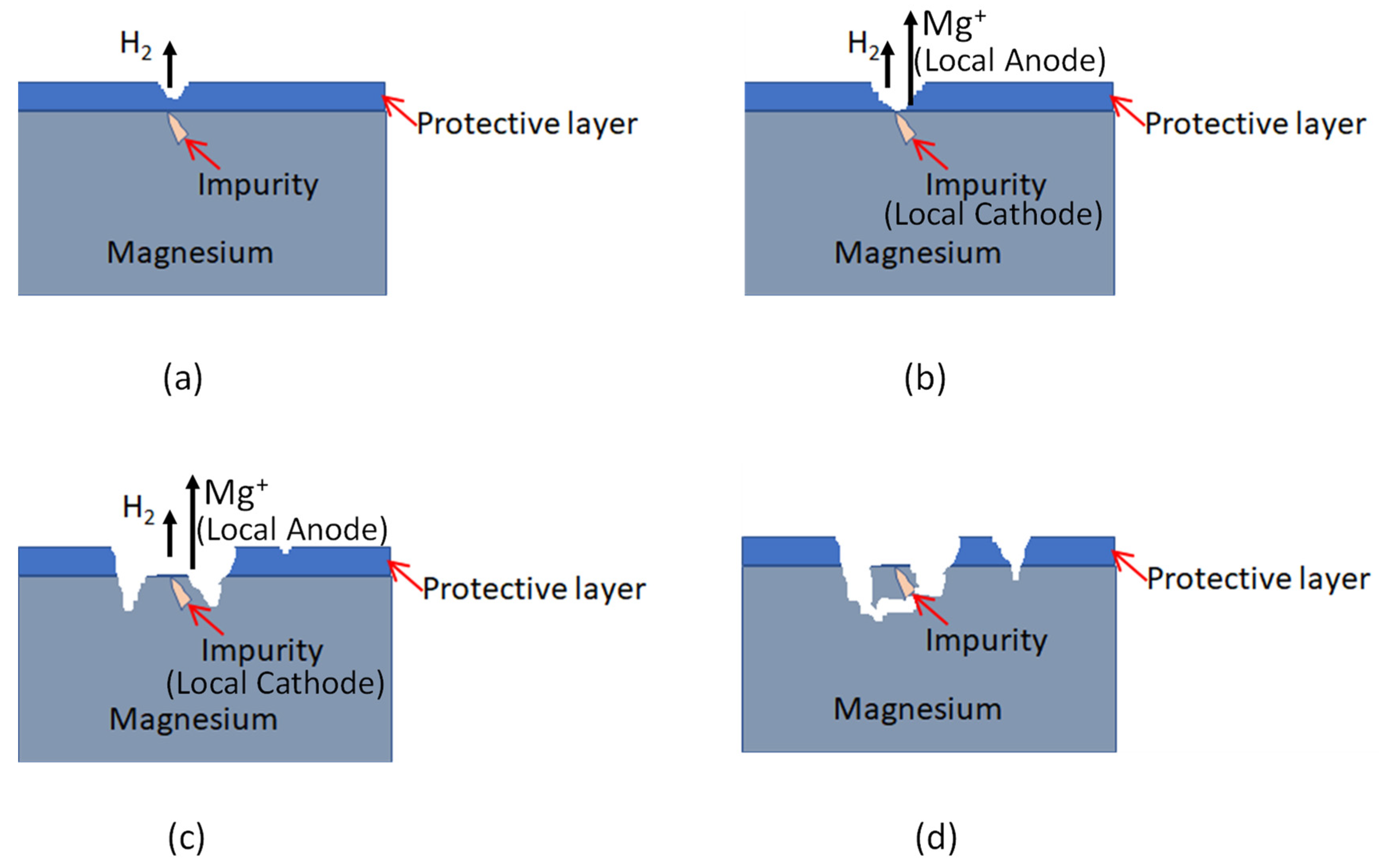
:1. Introduction
2. Materials and Methods
2.1. Magnesium Alloy WE43MEO
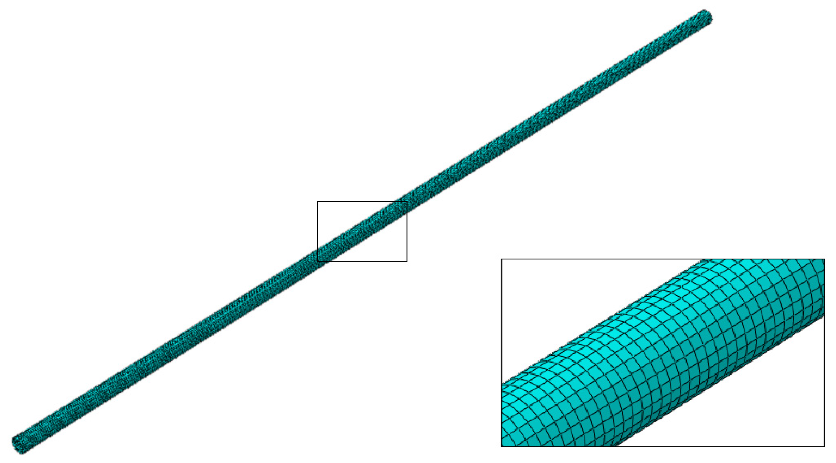
2.2. Mechanical Characterization
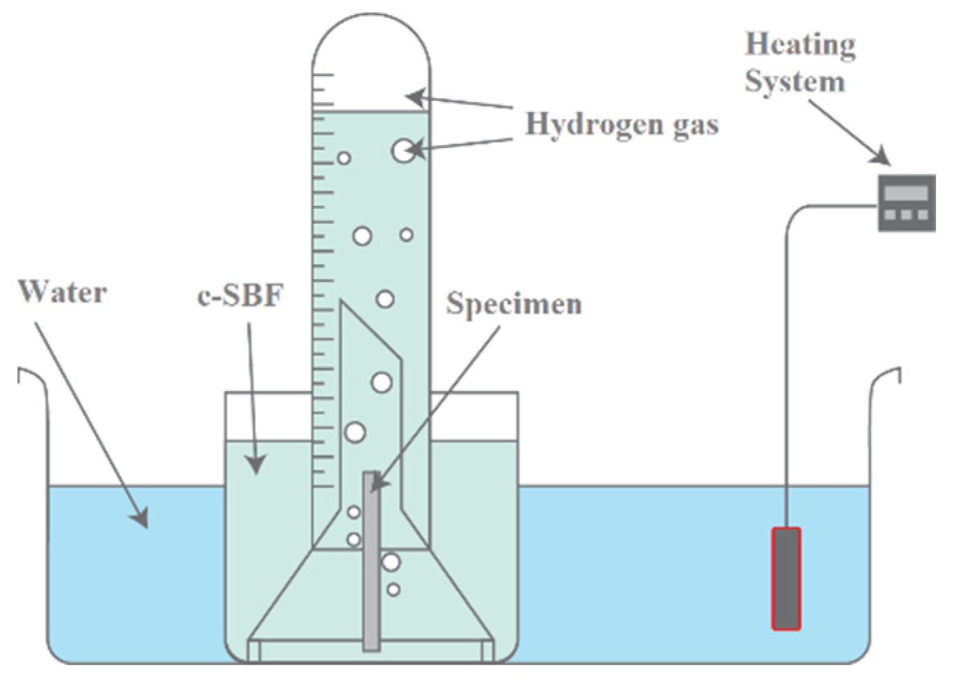
2.3. In Vitro Biodegradation Test
2.4. Determining the Rate of Biodegradation
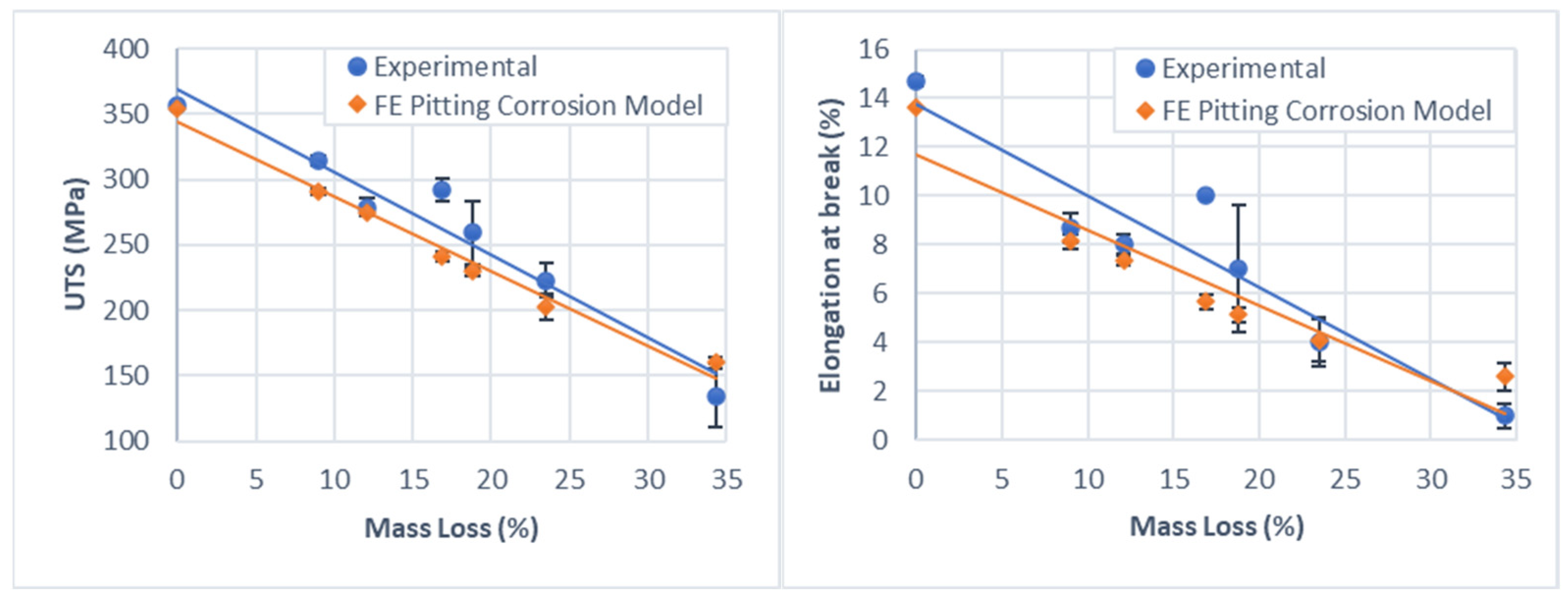
2.5. Biodegradation Effect on Mechanical Properties
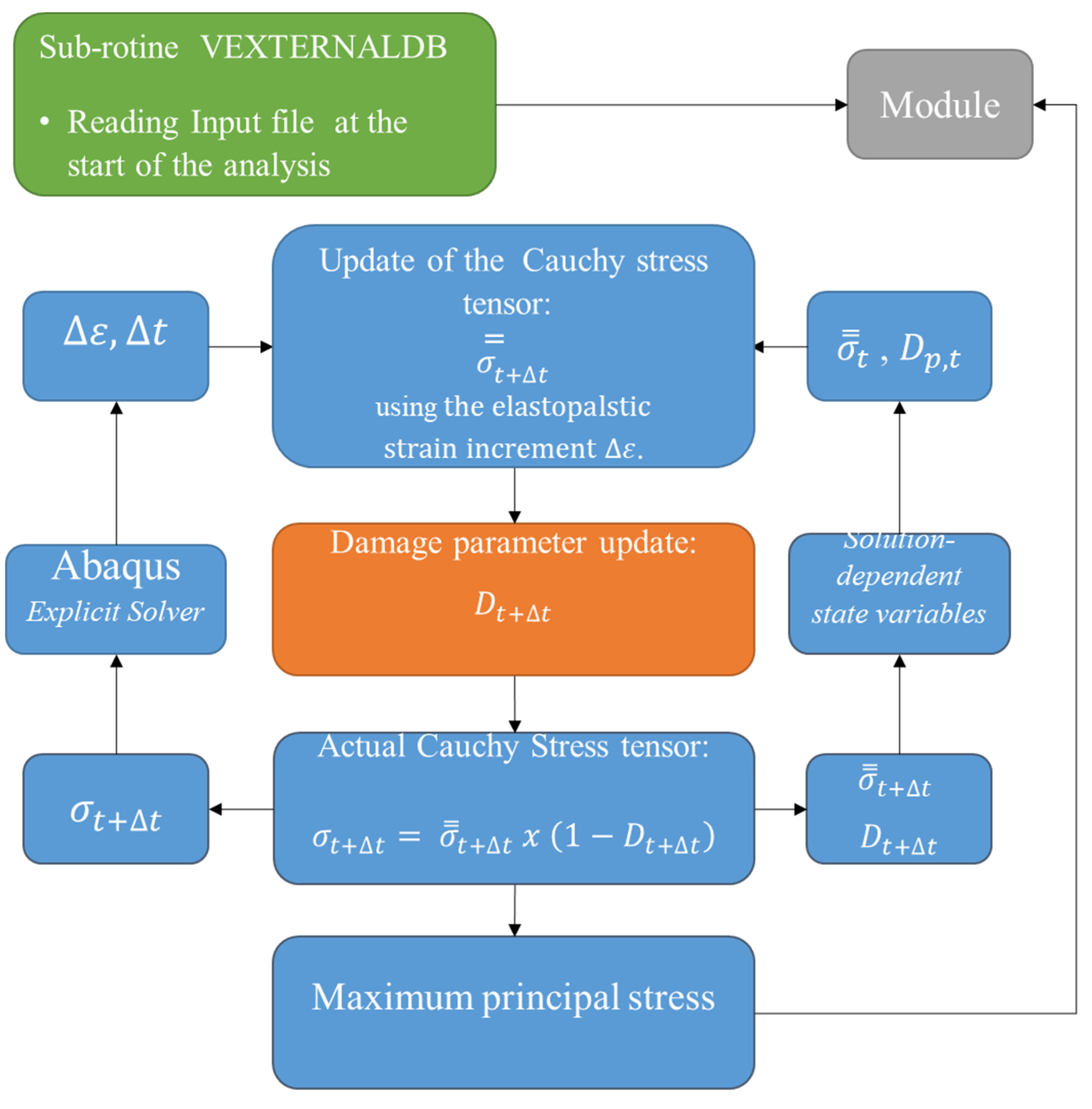
2.6. Implementation of the Biodegradation Model
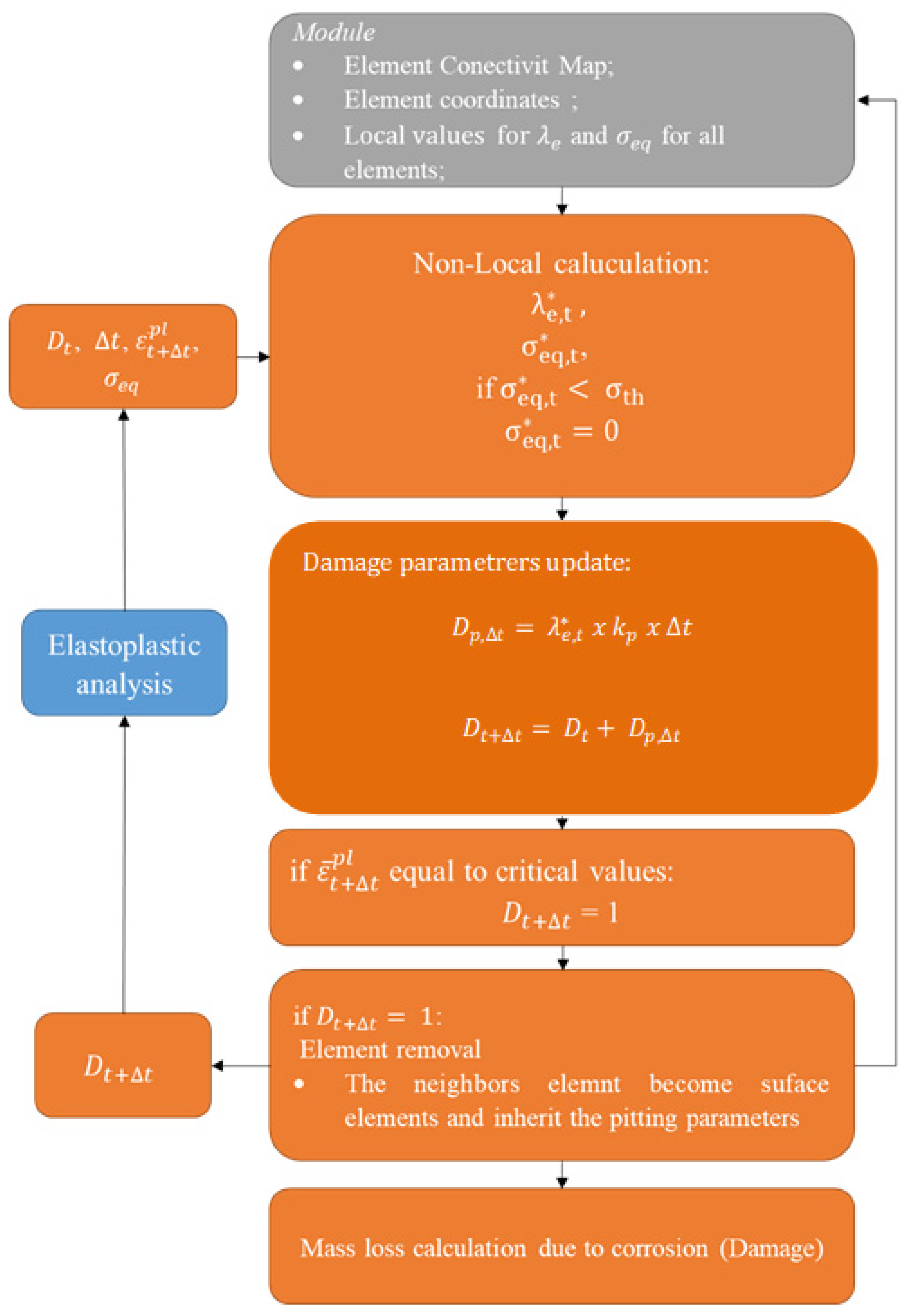
2.7. Mathematical Description of the Model
- The generation of the element connectivity map, or identification of neighboring elements to each element. Neighboring elements are those that share a face between themselves.
- The generation of coordinate and volume maps.
- The determination of the elements located at the surface of the model.
- The assignment of initial local pitting parameters to each of the elements located at the initial surface of the model, according to the Weibull distribution.
2.8. Simulation of In Vitro Biodegradation Experiments
2.9. Calibration Strategy–Localized Corrosion Model
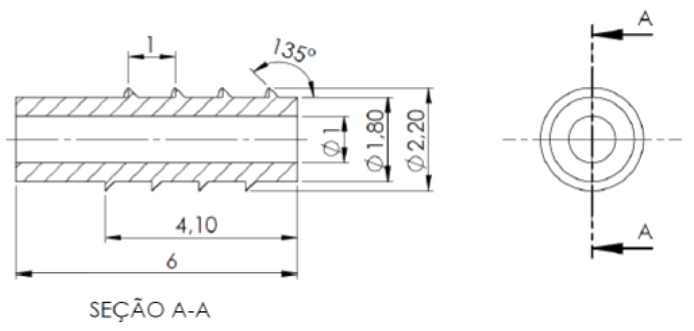
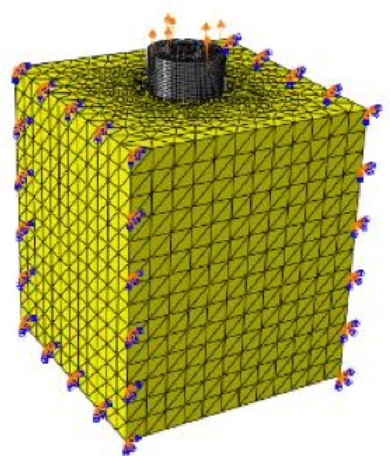
2.10. Case Study–Orthopedic Screw Pull-Out Testing
3. Results
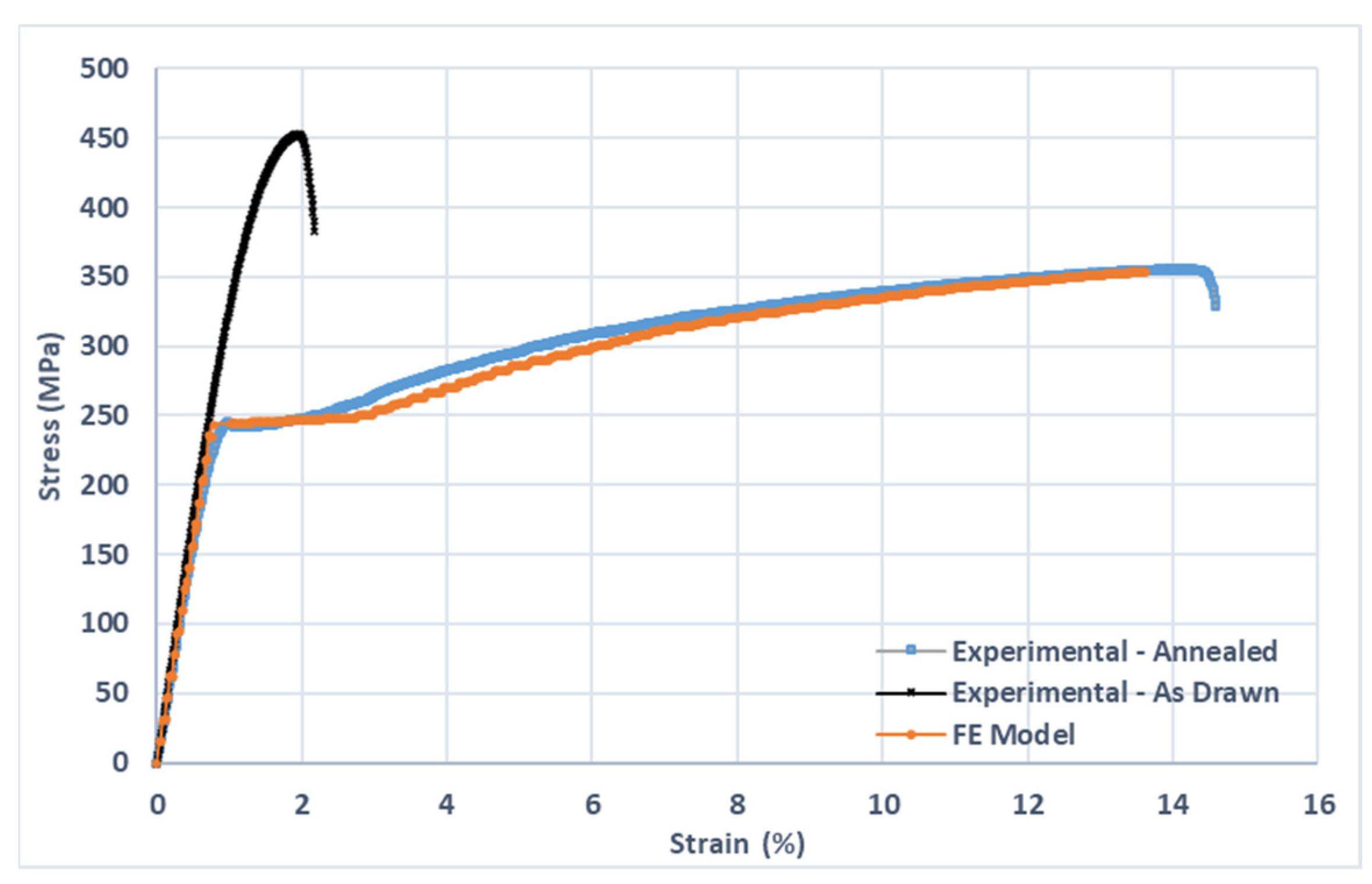
3.1. Mechanical Characterization Tests
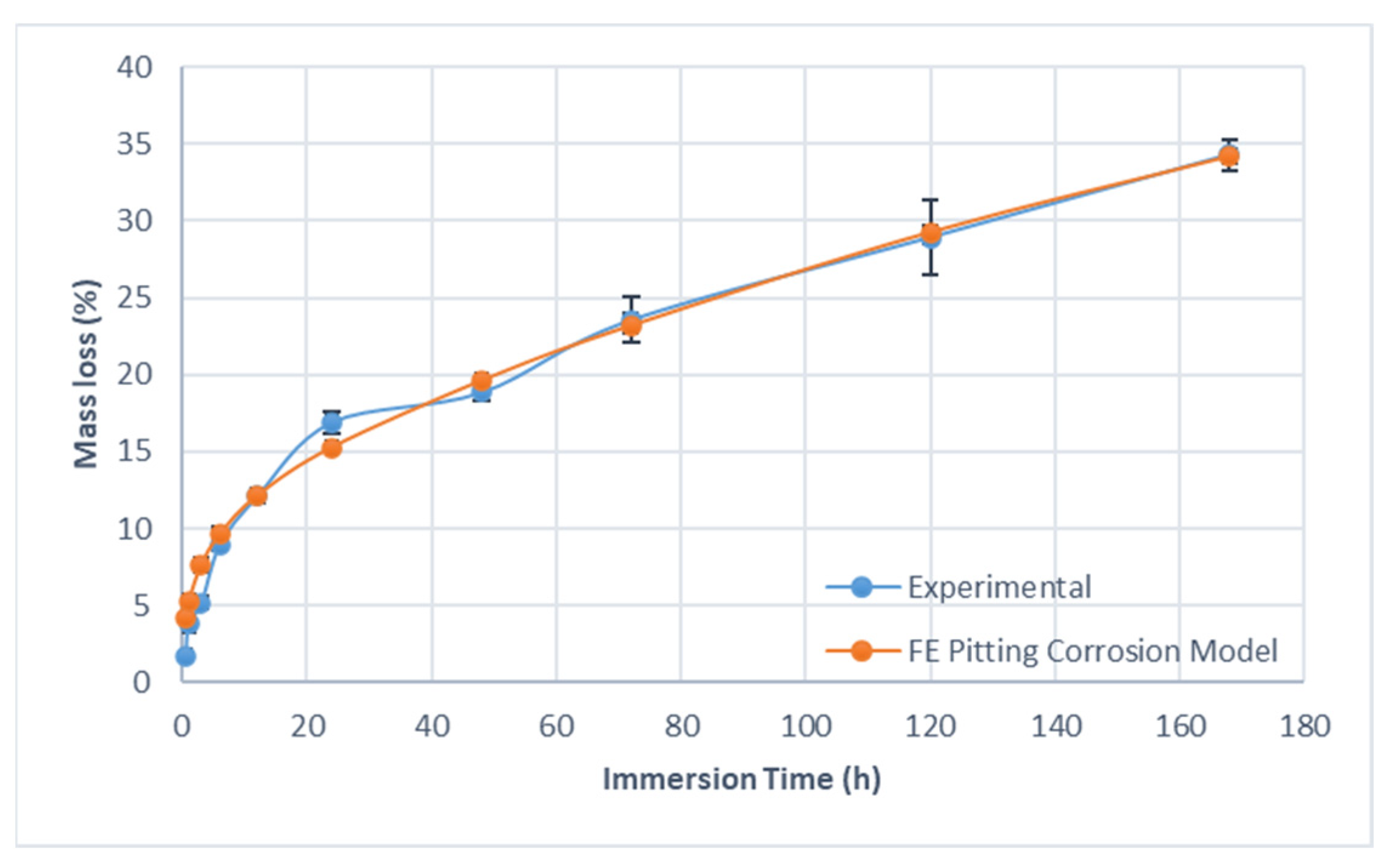
3.2. Determining the Biodegradation Rate
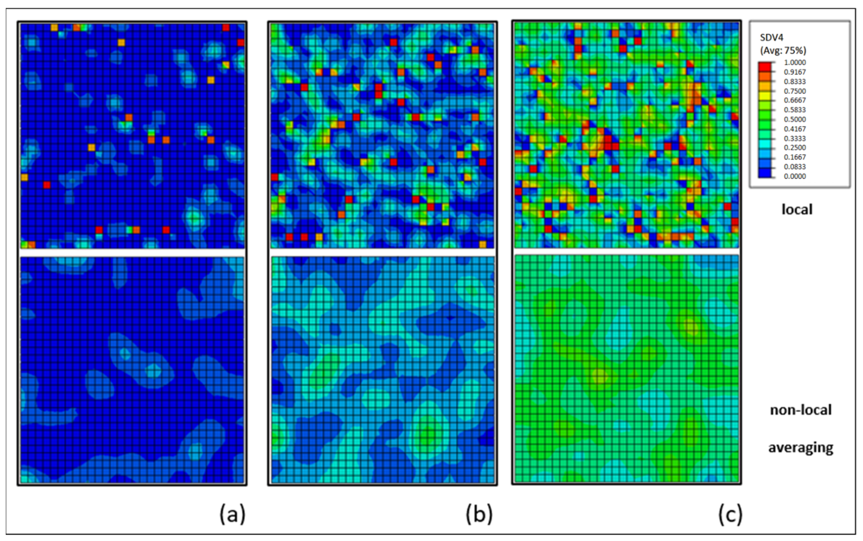
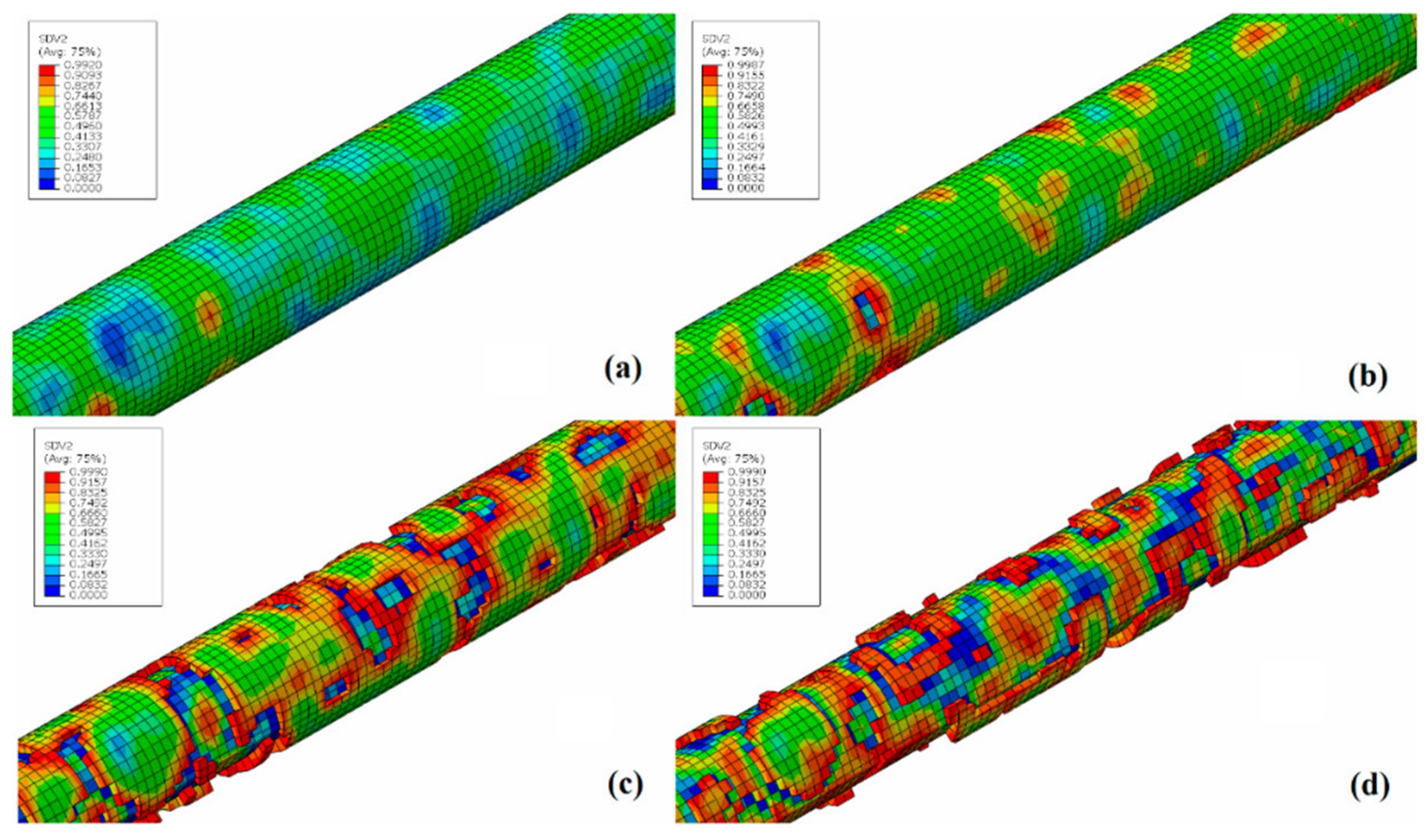
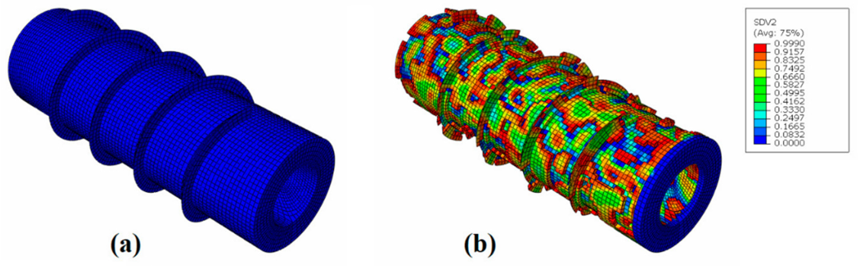
3.3. Localized Corrosion Model
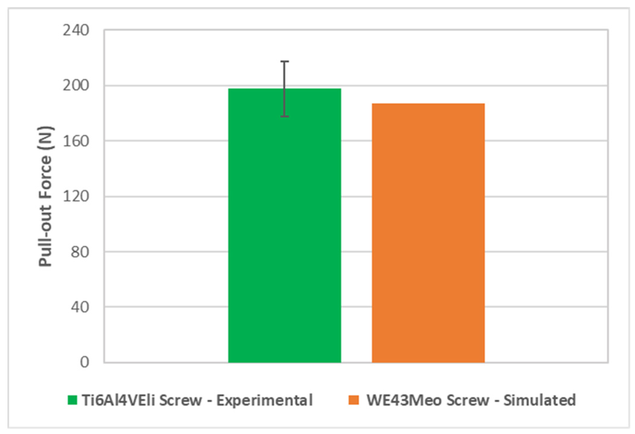
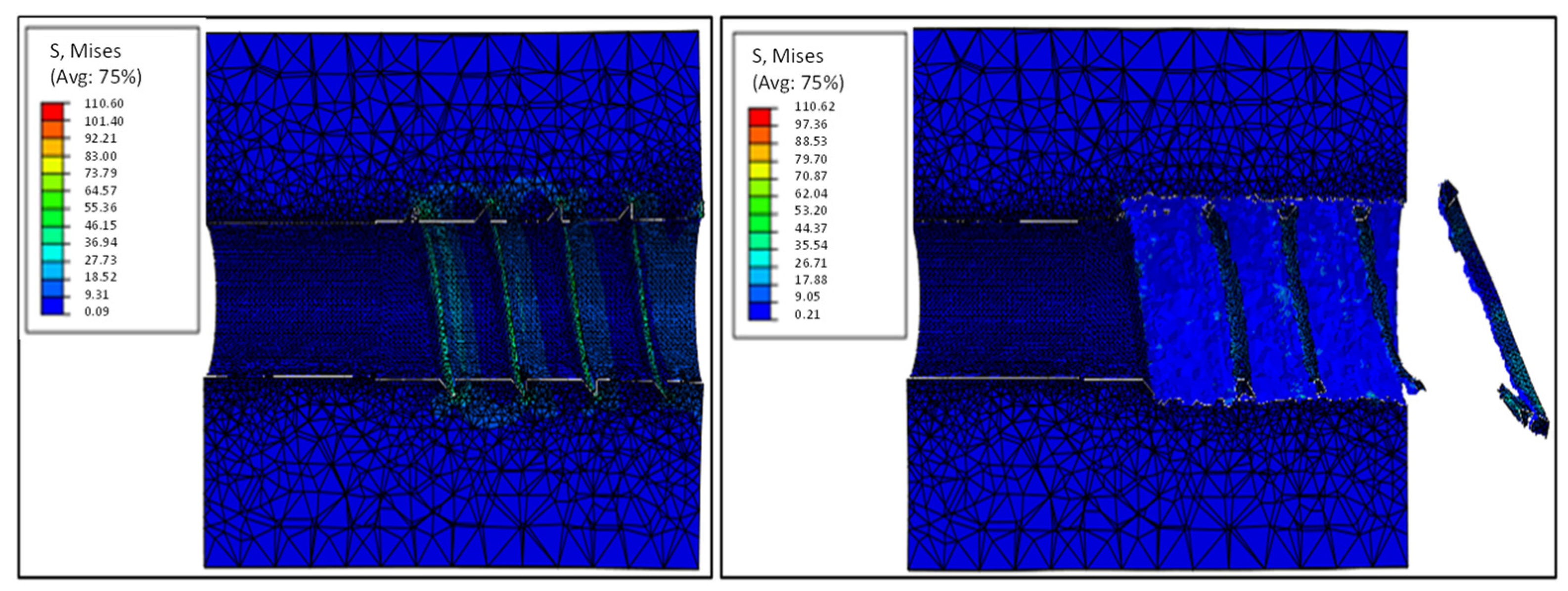
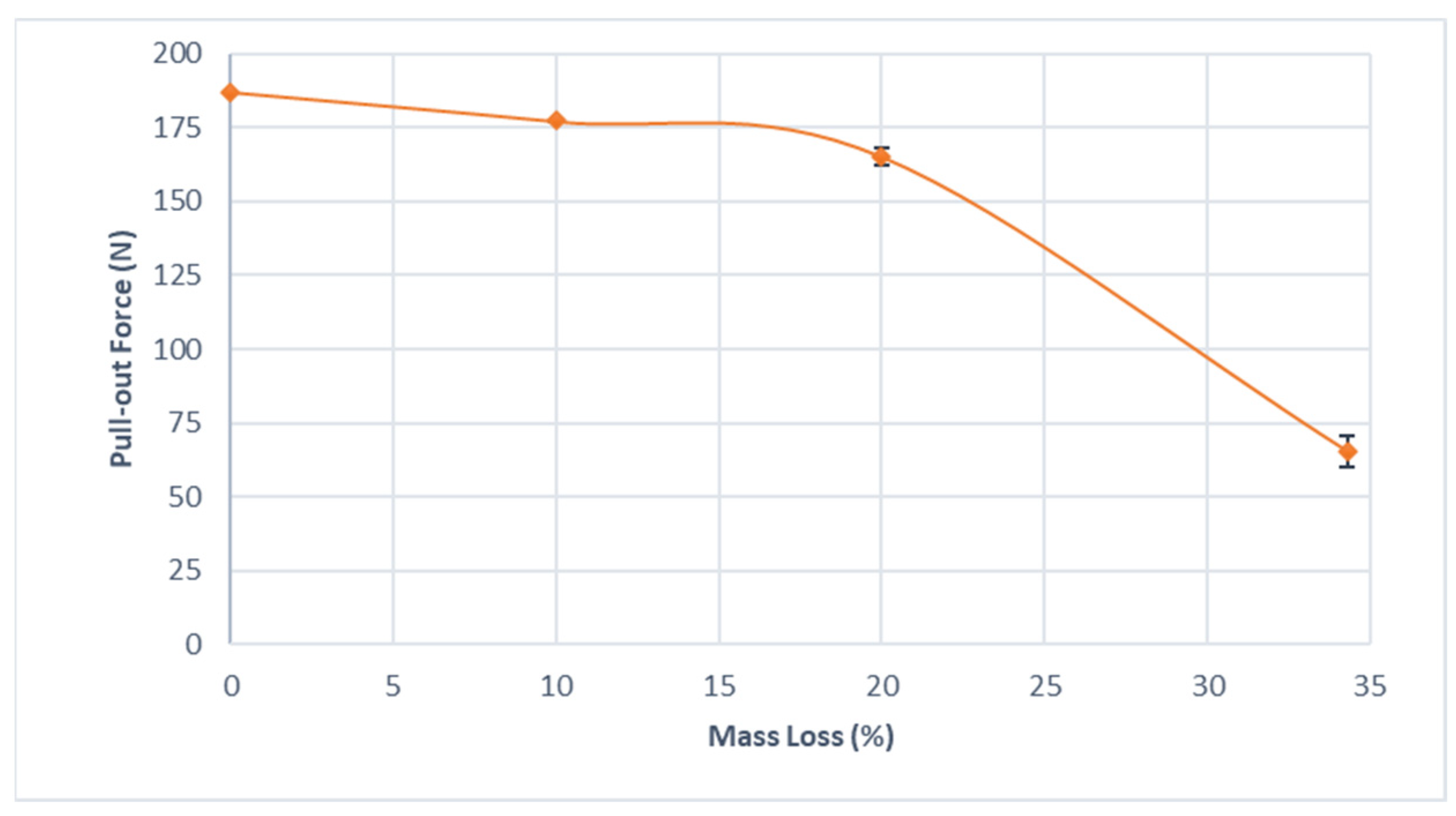
3.4. Case Study–Orthopedic Screw Pull-Out Testing
4. Conclusions
Author Contributions
Funding
Institutional Review Board Statement
Informed Consent Statement
Data Availability Statement
Conflicts of Interest
References
- Schatzker, J.; Marvin, T.; Terry, S. Axelrod. The Rationale of Operative Fracture Care; Springer: Berlin/Heidelberg, Germany, 2005; Volume 24. [Google Scholar]
- Tiwari, H.; Mhaisekar, P. An Incisive, In-Depth Analysis on the Bone Screw System Market. 2019. Available online: https://www.futuremarketinsights.com/reports/bone-screw-system-market (accessed on 10 October 2022).
- Öcal, E.B.; Esen, Z.; Aydınol, K.; Dericioğlu, A.F. Comparison of the short and long-term degradation behaviors of as-cast pure Mg, AZ91 and WE43 alloys. Mater. Chem. Phys. 2020, 241, 122350. [Google Scholar] [CrossRef]
- Abdalla, M.; Joplin, A.; Elahinia, M.; Ibrahim, H. Corrosion modeling of magnesium and its alloys for biomedical applications: Review. Corros. Mater. Degrad. 2020, 1, 11. [Google Scholar] [CrossRef]
- Minkowitz, R.B.; Bhadsavle, S.; Walsh, M.; Egol, K.A. Removal of Painful Orthopaedic. J. Bone Jt. Surg. 2007, 89, 1906–1912. [Google Scholar] [CrossRef]
- Waizy, H.; Diekmann, J.; Weizbauer, A.; Reifenrath, J.; Bartsch, I.; Neubert, V.; Windhagen, H. In vivo study of a biodegradable orthopedic screw (MgYREZr-alloy) in a rabbit model for up to 12 months. J. Biomater. Appl. 2014, 28, 667–675. [Google Scholar] [CrossRef]
- Seitz, J.; Lucas, A.; Kirschner, M. Magnesium-Based Compression Screws: A Novelty in the Clinical Use of Implants. JOM 2016, 68, 1177–1182. [Google Scholar] [CrossRef]
- Witte, F. The history of biodegradable magnesium implants: A review. Acta Biomater. 2010, 6, 1680–1692. [Google Scholar] [CrossRef] [PubMed]
- Witte, F.; Eliezer, A. Biodegradable metals. Degrad. Implant. Mater. 2012, 9781461439, 93–109. [Google Scholar]
- Hou, R.; Victoria-Hernandez, J.; Jiang, P.; Willumeit-Römer, R.; Luthringer-Feyerabend, B.; Yi, S.; Feyerabend, F. In vitro evaluation of the ZX11 magnesium alloy as potential bone plate: Degradability and mechanical integrity. Acta Biomater. 2019, 97, 608–622. [Google Scholar] [CrossRef]
- Gastaldi, D.; Sassi, V.; Petrini, L.; Vedani, M.; Trasatti, S.; Migliavacca, F. Continuum damage model for bioresorbable magnesium alloy devices—Application to coronary stents. J. Mech. Behav. Biomed. Mater. 2011, 4, 352–365. [Google Scholar] [CrossRef]
- Grogan, J.A.; O’brien, B.J.; Leen, S.B.; McHugh, P.E. A corrosion model for bioabsorbable metallic stents. Acta Biomater. 2011, 7, 3523–3533. [Google Scholar] [CrossRef]
- Kirkland, N.T.; Birbilis, N.; Staiger, M.P. Assessing the corrosion of biodegradable magnesium implants: A critical review of current methodologies and their limitations. Acta Biomater. 2012, 8, 925–936. [Google Scholar] [CrossRef] [PubMed]
- Krüger, D.; Zeller-Plumhoff, B.; Wiese, B.; Yi, S.; Zuber, M.; Wieland, D.F.; Willumeit-Römer, R. Assessing the microstructure and in vitro degradation behavior of Mg-xGd screw implants using µCT. J. Magnes. Alloy. 2021, 9, 2207–2222. [Google Scholar] [CrossRef]
- van Gaalen, K.; Gremse, F.; Benn, F.; McHugh, P.E.; Kopp, A.; Vaughan, T.J. Automated ex-situ detection of pitting corrosion and its effect on the mechanical integrity of rare earth magnesium alloy-WE43. Bioact. Mater. 2022, 8, 545–558. [Google Scholar] [CrossRef] [PubMed]
- van Gaalen, K.; Quinn, C.; Benn, F.; McHugh, P.E.; Kopp, A.; Vaughan, T.J. Linking the effect of localised pitting corrosion with mechanical integrity of a rare earth magnesium alloy for implant use. Bioact. Mater. 2023, 21, 32–43. [Google Scholar] [CrossRef] [PubMed]
- Mraied, H.; Wang, W.; Cai, W. Influence of chemical heterogeneity and microstructure on the corrosion resistance of biodegradable WE43 magnesium alloys. J. Mater. Chem. B 2019, 7, 6399–6411. [Google Scholar] [CrossRef]
- Maier, P.; Griebel, A.J.; Scheffler, O.; Schaffer, J.E. Remaining strength of cold drawn and aged WE43 wires after corrosion. Eur. Cells Mater. 2015, 30 (Suppl. S3), 47. [Google Scholar]
- Oyane, A.; Kim, H.M.; Furuya, T.; Kokubo, T.; Miyazaki, T.; Nakamura, T. Preparation and assessment of revised simulated body fluids. J. Biomed. Mater. Res. 2002, 65A, 188–195. [Google Scholar] [CrossRef] [PubMed]
- Song, G.; Atrens, A.; Stjohn, D. An Hydrogen Evolution Method for the Estimation of the Corrosion Rate of Magnesium Alloys. In Magnesium Technology; Hryn, J.N., Ed.; Springer: Berlin/Heidelberg, Germany, 2001. [Google Scholar]
- Yang, L.; Zhang, E. Biocorrosion behavior of magnesium alloy in different simulated fl uids for biomedical application. Mater. Sci. Eng. C 2009, 29, 1691–1696. [Google Scholar] [CrossRef]
- Ma, S.; Zhou, B.; Markert, B. Numerical simulation of the tissue differentiation and corrosion process of biodegradable magnesium implants during bone fracture healing. Zamm Z. Fur Angew. Math. Und Mech. 2018, 98, 2223–2238. [Google Scholar] [CrossRef]
- Boland, E.L.; Shirazi, R.N.; Grogan, J.A.; McHugh, P.E. Mechanical and Corrosion Testing of Magnesium WE43 Specimens for Pitting Corrosion Model Calibration. Adv. Eng. Mater. 2018, 20, 1–11. [Google Scholar] [CrossRef]
- Leggon, R.; Lindsey, R.W.; Doherty, B.J.; Alexander, J.; Noble, P. The holding strength of cannulated screws compared with solid core screws in cortical and cancellous bone. J. Orthop. Trauma. 1993, 7, 450–457. [Google Scholar] [CrossRef] [PubMed]
- Ketata, H.; Affes, F.; Kharrat, M.; Dammak, M. A comparative study of tapped and untapped pilot holes for bicortical orthopedic screws–3D finite element analysis with an experimental test. Biomed. Eng. Biomed. Tech. 2019, 64, 563–570. [Google Scholar] [CrossRef]
- Griebel, A.J.; Schaffer, J.E.; Hopkins, T.M.; Alghalayini, A.; Mkorombindo, T.; Ojo, K.O.; Pixley, S.K. An in vitro and in vivo characterization of fine WE43B magnesium wire with varied thermomechanical processing conditions. J. Biomed. Mater. Res.-Part B Appl. Biomater. 2018, 106, 1987–1997. [Google Scholar] [CrossRef] [PubMed]
- Liu, D.; Ding, Y.; Guo, T.; Qin, X.; Guo, C.; Yu, S.; Lin, S. Influence of fine-grain and solid-solution strengthening on mechanical properties and in vitro degradation of WE43 alloy. Biomed. Mater. (Bristol) 2014, 9, 015014. [Google Scholar] [CrossRef]
- Erinc, M.; Sillekens, W.H.; Mannens RG, T.M.; Werkhoven, R.J. Applicability of Existing Magnesium Alloys as Biomedical Implant Materials. In Magnesium Technology; Nyberg, E.A., Agnew, S.R., Neelameggham, N.R., Pekguleryuz, M.O., Eds.; TMS (The Minerals, Metals & Materials Society): San Francisco, CA, USA, 2009. [Google Scholar]
- Zheng, Y.F.; Gu, X.N.; Witte, F. Biodegradable metals. Mater. Sci. Eng. R Rep. 2014, 77, 1–34. [Google Scholar] [CrossRef]
- Ascencio, M.; Pekguleryuz, M.; Omanovic, S. An investigation of the corrosion mechanisms of WE43Mg alloy in a modified simulated body fluid solution: The effect of electrolyte renewal. Corros. Sci. 2015, 91, 297–310. [Google Scholar] [CrossRef]
- Galvin, E.; O’brien, D.; Cummins, C.; Mac Donald, B.J.; Lally, C. A strain-mediated corrosion model for bioabsorbable metallic stents. Acta Biomater. 2017, 55, 505–517. [Google Scholar] [CrossRef]
- Razek. Relatório de Ensaio 2954/15-Ensaio de Arrancamento. São Carlos: [s.n.].
- Horak, Z.; Dvorak, K.; Zarybnicka, L.; Vojackova, H.; Dvorakova, J.; Vilimek, M. Experimental measurements of mechanical properties of pur foam used for testing medical devices and instruments depending on temperature, density and strain rate. Materials 2020, 13, 4560. [Google Scholar] [CrossRef]
- Chapman, J.R.; Harrington, R.M.; Lee, K.M.; Anderson, P.A.; Tencer, A.F.; Kowalski, D. Factors affecting the pullout strength of cancellous bone screws. J. Biomech. Eng. 1996, 118, 391–398. [Google Scholar] [CrossRef]
- Ilyas, A.M.; Mahoney, J.M.; Bucklen, B.S. A Mechanical Comparison of the Compressive Force Generated by Various Headless Compression Screws and the Impact of Fracture Gap Size. Hand 2019, 16, 604–611. [Google Scholar] [CrossRef]


| Thermal Condition | Modulus of Elasticity (GPa) | UTS (MPa) | Yield Stress (MPa) | Elongation at Break (%) |
|---|---|---|---|---|
| As-Drawn | 35.6 ± 2.0 | 454.4 ± 8.3 | 394.9 ± 10.2 | 2.20 ± 0.02 |
| Annealed | 31.5 ± 0.6 | 356.7 ± 2.4 | 245.9 ± 8.5 | 14.7 ± 0.2 |
| γ | ψ | β | kpv |
|---|---|---|---|
| 0.4 | 1 | 0.8 | 0.3125t−0.68 |
Publisher’s Note: MDPI stays neutral with regard to jurisdictional claims in published maps and institutional affiliations. |
© 2022 by the authors. Licensee MDPI, Basel, Switzerland. This article is an open access article distributed under the terms and conditions of the Creative Commons Attribution (CC BY) license (https://creativecommons.org/licenses/by/4.0/).
Share and Cite
Saconi, F.; Diaz, G.H.; Vieira, A.C.; Ribeiro, M.L. Experimental Characterization and Numerical Modeling of the Corrosion Effect on the Mechanical Properties of the Biodegradable Magnesium Alloy WE43 for Orthopedic Applications. Materials 2022, 15, 7164. https://doi.org/10.3390/ma15207164
Saconi F, Diaz GH, Vieira AC, Ribeiro ML. Experimental Characterization and Numerical Modeling of the Corrosion Effect on the Mechanical Properties of the Biodegradable Magnesium Alloy WE43 for Orthopedic Applications. Materials. 2022; 15(20):7164. https://doi.org/10.3390/ma15207164
Chicago/Turabian StyleSaconi, Felipe, Geraldine Hincapie Diaz, André Costa Vieira, and Marcelo Leite Ribeiro. 2022. "Experimental Characterization and Numerical Modeling of the Corrosion Effect on the Mechanical Properties of the Biodegradable Magnesium Alloy WE43 for Orthopedic Applications" Materials 15, no. 20: 7164. https://doi.org/10.3390/ma15207164