
Enhanced Energy Storage Performance of PVDF-Based Composites Using BN@PDA Sheets and Titania Nanosheets
by
 ,
,
Congcong Zhu
1,2, 
Jinghua Yin
1,2,*,
Yu Feng
2,
Jialong Li
3,
Yanpeng Li
1,
He Zhao
2,
Dong Yue
1 and
Xiaoxu Liu
3,* 1
School of Materials Science and Chemical Engineering, Harbin University of Science and Technology, Harbin 150080, China
2
Key Laboratory of Engineering Dielectrics and Its Application, Ministry of Education, Harbin University of Science and Technology, Harbin 150080, China
3
School of Materials Science and Engineering, Shaanxi University of Science and Technology, Xi’an 710021, China
*
Authors to whom correspondence should be addressed.
Materials 2022, 15(13), 4370; https://doi.org/10.3390/ma15134370
Submission received: 6 May 2022
/
Revised: 28 May 2022
/
Accepted: 5 June 2022
/
Published: 21 June 2022
Abstract
:With the rapid development of modern electrical and electronic applications, the demand for high-performance film capacitors is becoming increasingly urgent. The energy density of a capacitor is dependent on permittivity and breakdown strength. However, the development of polymer-based composites with both high permittivity (εr) and breakdown strength (Eb) remains a huge challenge. In this work, a strategy of doping synergistic dual-fillers with complementary functionalities into polymer is demonstrated, by which high εr and Eb are obtained simultaneously. Small-sized titania nanosheets (STNSs) with high εr and high-insulating boron nitride sheets coated with polydopamine on the surface (BN@PDA) were introduced into poly(vinylidene fluoride) (PVDF) to prepare a ternary composite. Remarkably, a PVDF-based composite with 1 wt% BN@PDA and 0.5 wt% STNSs (1 wt% PVDF/BN@PDA−STNSs) shows an excellent energy storage performance, including a high εr of ~13.9 at 1 Hz, a superior Eb of ~440 kV/mm, and a high discharged energy density Ue of ~12.1 J/cm3. Moreover, the simulation results confirm that BN@PDA sheets improve breakdown strength and STNSs boost polarization, which is consistent with the experimental results. This contribution provides a new design paradigm for energy storage dielectrics.
1. Introduction
Polymer dielectric capacitors have attracted much attention due to their simple fabrication, excellent mechanical property, high power density, and high breakdown strength. Polymer dielectric capacitors are widely used in electronic and electrical equipment, such as hybrid electric vehicles, power grid systems, aerospace and radar technology, etc. [1,2,3,4]. However, the low energy storage density of polymer dielectric capacitors increases the size and cost of dielectric capacitors and limits their application in modern electric devices. For example, the DC bus capacitors in an electric vehicle power inverter can account for ~35% of the inverter volume and ~23% of the inverter weight [5]. Therefore, polymer dielectrics with high energy storage density are very desirable in developing highly integrated and reliable capacitors.
The discharged energy density Ue of dielectrics is determined by the applied electric field E and dielectric polarization P as [6]: , where Pm and Pr are the maximum polarization and remnant polarization, respectively. Consequently, high Ue can be obtained by high Pm, low Pr, and large Eb. For linear dielectric materials, the equation can be defined as [7]: , where ε0 is the vacuum permittivity (8.85 × 10⁻¹² F/m), and εr means the relative permittivity. Apparently, dielectrics with high energy density should possess both high εr and Eb. Polymer/ceramic composites exhibit a promising strategy that has the potential of combining the high Eb of polymer matrix and large εr of the ceramic fillers.
Following the above consideration, in order to improve the polarization and hence εr, numerous efforts have been made in preparing 0–3 composites with high filler contents [8,9]. Nevertheless, more interfacial imperfections (such as structural defects, voids, pores, and cracks) and particle agglomeration are also introduced, resulting in increased dielectric loss and decreased Eb. It is well known that large-aspect-ratio one dimensional (1D) and two dimensional (2D) fillers could lead to a higher εr of composites at a lower filler content in comparison with that of the zero dimensional (0D) fillers [10,11,12,13]. Yet, the large difference in εr between ceramic fillers and polymer matrix result in electric field distortion at the interface and decreased Eb.
In order to enhance the Eb and Ue of polymer-based composites, tremendous effort has been made [14,15,16]. This study found that adding wide band-gap 2D fillers into the polymer matrix can enhance the Eb of composites. The 2D fillers can act as conduction barriers to limit the charge migration and increase path tortuosity during breakdown. For example, Zhu et al. introduced the ultra-thin boron nitride nanosheets (BNNS) into a PVDF matrix and a high Eb of 612 kV/mm and an Ue of 14.3 J/cm3 were obtained [17]. However, the permittivity of wide band-gap fillers is usually low, resulting in the decrease in the permittivity of composites. There is a conflict between high Eb and εr in the preparation of high-energy storage density composites. In order to solve this problem, many innovative strategies are proposed, including filler modification and optimization, filler orientation distribution, etc., which have greatly improved energy density [18,19,20,21]. Unfortunately, the complex process of filler modification, optimization, and orientation causes a great waste of experimental cost and time and also increases the difficulty of preparation.
Herein, we report a class of solution-processable PVDF-based composites consisting of two 2D fillers with complementary functionalities, including boron nitride sheets coated with polydopamine (BN@PDA) with high Eb and small-sized titania nanosheets (STNSs) with high permittivity. The PVDF/BN@PDA binary composites without STNSs were prepared and tested for comparison. The results show that the ternary polymer-based composites possess simultaneously increased permittivity and breakdown strength that lead to excellent energy storage performance in comparison with PVDF/BN@PDA binary composites and our previous work [22]. This work provides an easy route for the use of 2D fillers to improve the energy density of composites.
2. Materials and Methods
2.1. Materials
Boron nitride (h-BN, 99.9% purity) powder was purchased from Shanghai Chaowei Nanotechnology Co., Ltd. (Shanghai, China). Dopamine hydrochloride and tris-(hydroxymethyl)-aminomethane (Tris) were purchased from Aladdin. Poly(vinylidene fluoride) (PVDF) powder with the number-average molecular weight of 534,000 was provided by Sigma-Aldrich Co., Ltd. (Shanghai, China). Potassium carbonate (K2CO3), lithium carbonate (Li2CO3), Rutile titania nanoparticles (TiO2, diameter of 60 nm), and tetrabutylammonium hydroxide (TBAOH) were purchased from Aladdin Industrial Corporation. The N, N-dimethylformamide (DMF) and anhydrous ethanol were provided by Tianjin Fuyu Fine Co., Ltd. (Tianjing, China).
2.2. Preparation of STNSs and Surface Coating of BT by PDA
STNSs were prepared via the top-down exfoliation method [23]. The PDA was coated on the surface of sheets to obtain BN sheets with good dispersion and compatibility. First, 500 mL aqueous solution of Tris was prepared and the pH was adjusted to 8.5; then, 0.8 g dopamine hydrochloride was dispersed into the above solution. Second, the BN sheets were added into the above solution and stirred at 60 °C for 12 h. The obtained BN@PDA sheets were centrifuged and washed with deionized water several times.
2.3. Preparation of PVDF/BN@PDA−STNSs Nanocomposites
Pure PVDF, PVDF/BN@PDA, and PVDF/BN@PDA−STNSs composites were prepared via simple physical blending and hot-press method. The 0.5 wt% PVDF/STNSs showed an excellent energy storage performance in our previous work [24]. The appropriate amount of BN@PDA and 0.5 wt% STNSs were sequentially dissolved in 7 mL DMF solvent to form a suspension. The suspension was sonicated to improve fillers’ dispersibility, then mixed with 1 g PVDF powder and stirred for 24 h. The suspension was poured into a clean glass and dried at 80 °C for 10 h. Finally, the samples were hot-pressed at 180 °C for 30 min under 20 MPa pressure. The thickness of the final composite films was approximately 20 ± 5 μm. The schematic illustration of synthesizing the ternary nanocomposites can be seen from Figure S1. In addition, PVDF/BN@PDA binary composites were prepared and tested for comparison.
2.4. Characterization
Scanning electron microscopy (SEM, Hitachi SU8020) and the transmission electron microscope (TEM, FEI TECNAI2-12) were used to investigate the surface morphology of BN@PDA and STNSs and the cross-sectional images of the polymer-based composites in this work. The wide-angle X-ray diffraction (XRD) system was performed on X-ray diffractometer (Ultima IV, Rigaku Corporation) using a CuKα source radiation operating at 40 kV and 40 mA. The FTIR spectra of pure PVDF and the composites were tested using JASCO 6100 equipment. At the beam line 1W2A in Beijing Synchrotron Radiation Facility, the small angle x-ray scattering (SAXS) experiments were carried out to research the microstructure of the composites. The storage ring was operated at 2.5 GeV with a current of about 80 mA. The 2D scattering patterns were collected by a Mar165-CCD-charged coupled device and the sample-to-detector distance in the beam direction was 1500 mm. Aluminum electrodes (25 mm in diameter) were deposited on both sides of the samples by vacuum evaporation for subsequent electrical measurements. A broadband impedance analyzer (GmbH Novocontrol Alpha-A) was used to conduct dielectric properties of composites at the frequency range of 100 Hz to 106 Hz. The AC breakdown strength test of composites was carried out via IEC 243. The polarization-electric field (P-E) loops of the composites were measured using the Radiant Premier II Ferroelectric Test System at a frequency of 100 Hz.
3. Results
3.1. Characterization of BN@PDA and STNSs
The morphologies of the BN@PDA and STNSs were characterized by SEM, and the typical images are shown in Figure 1a,b, respectively. The BN@PDA sheets possess a 2D multi-layered structure, and the STNSs present a typical 2D nanosheet structure. Typical TEM images of BN@PDA (Figure S2a,b) reveal that the thickness of PDA was of about 4 nm. The average lateral dimension (d) of BN@PDA as obtained was around 0.5–3 μm and the d of the STNSs was about 0.9–2.8 μm. The thickness of BN@PDA (Figure S3) was about 30–120 nm, and the thickness of the STNSs was about 3 nm, as shown in our previous work [24]. The EDS of BN@PDA is shown in Figure S4, and the presence of O, C, and N elements indicates that the PDA was successfully coated on the BN surface. The EDS of the STNSs is given in Figure S5; it shows the presence of Ti and O elements.
X-ray diffraction (XRD) spectra was used to investigate the crystallization and phase structure of BN@PDA and STNSs (Figure 1e). The peaks at approximately 26.7°, 41.5°, and 55.4° are assigned to the (002), (100) and (111) crystal planes of BN nanosheets, respectively. The characteristic (020) peak at 2θ = 9.6° confirms the successful preparation of STNSs. Fourier-transform infrared spectroscopy (FTIR) of BN@PDA and STNSs was carefully examined. As shown in Figure 1f, the peak located at 810 cm−1 corresponds to the B−N bending vibration of BN@PDA. The peaks located at 3405 and 1610 cm−1 correspond to the −OH stretching vibration and N−H bending vibration of BN@PDA, respectively. As for the STNSs, their characteristic absorption peak of is revealed near ~957 cm−1. The −OH stretching vibration and bending vibration peaks appear at 3405 and 1684 cm−1, respectively. The −CH3 bending vibration and C−N stretching vibration peaks are located at 1370 and 1476 cm−1, respectively, which may have been introduced by TBA+ on the STNSs surface.
3.2. Characterization of PVDF/BN@PDA−STNSs Composites
The dispersion and morphologies of the BN@PDA in the PVDF composites were characterized using SEM (Figure S6). As in Figure S6a, most of the BN@PDA sheets were dispersed homogeneously and well aligned in a certain direction in the matrix when the BN@PDA doping content was 1 wt%. A large amount of sheets aggregated inevitably when the content of BN@PDA was at 10 wt%, as shown in Figure S6b. The typical cross-sectional SEM images of the 1 wt% PVDF/BN@PDA−STNSs composite is shown in Figure 2. The BN@PDA and STNSs uniformly dispersed in the PVDF matrix, and no obvious agglomeration and defects can be observed. Abundant hydrogen bonds were formed by rich –OH on the fillers (BN@PDA and STNSs) and fluorine atoms of PVDF chains, which could enhance the dispersal homogeneity of fillers as well as improve the reciprocal interaction between the fillers and PVDF matrix [25,26]. The EDS results (Figure S7) indicate that that BN@PDA and STNSs were introduced into the PVDF matrix.
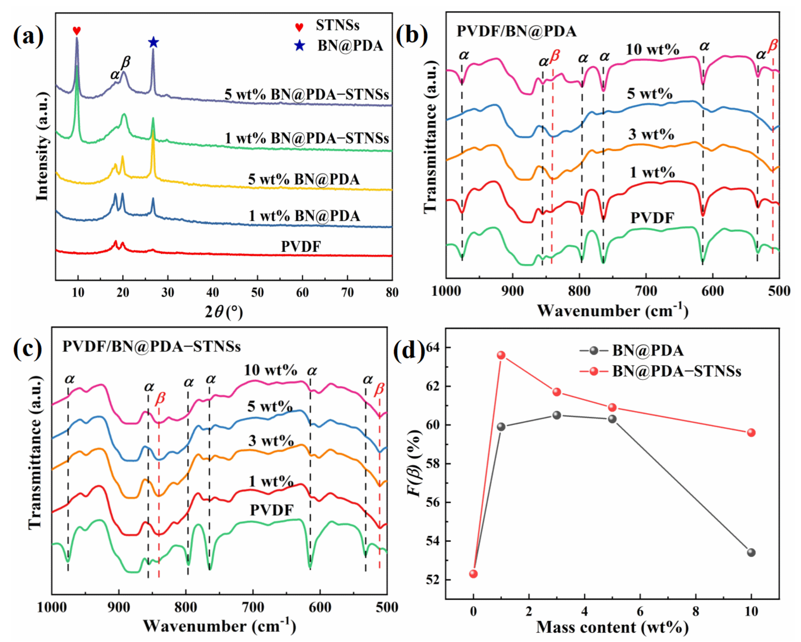
As illustrated in Figure 3a and Figure S8 of the XRD patterns for pure PVDF, PVDF/BN@PDA, and PVDF/BN@PDA−STNSs composites, the characteristic diffraction peaks of inorganic fillers and PVDF matrix were indexed. For example, the (020) plane of the STNSs are well indexed and the characteristic diffraction plane of (020) for BN@PDA sheets is at 2θ = 26.7°, respectively. In addition to the characteristic diffraction peaks of inorganic fillers, the characteristic diffraction peaks of the PVDF matrix can also be observed in the composites. The diffraction peaks of 2θ = 18.5°and 20.2°are consistent with the (020) plane of α phase and (110)(200) plane of β phase. Compared with the pure PVDF and PVDF/BN@PDA binary composites, the PVDF/BN@PDA−STNSs composites possess attenuated intensity of an α phase peak and enhanced intensity of a β phase peak, which indicates that incorporating STNSs is an effective method to obtain a high concentration of polar β phase PVDF. The high content of β phase PVDF is beneficial in improving the permittivity of the composites [27].
To quantitatively calculate the β phase content, FTIR results were obtained on pure PVDF, PVDF/BN@PDA, and PVDF/BN@PDA−STNSs composites, as shown in Figure S9. Compared with pure PVDF, for both series of composites, the hydroxyl group bending vibration and stretching vibration appear at 1684 and 3405 cm−1, respectively. The hydrogen bonds generated between the fillers and fluorine atom of PVDF chains via −OH···F-H might form a β phase and more dipoles at the interfaces [28]. Figure 3b,c show the enlarged image of FTIR spectra in the wavelength range of 500–1000 cm−1. The absorption peaks located at 533 (CF2 bonds bending), 614, and 766 (CF2 skeletal bending), 796, 855 and 976 cm−1 (CH2 rocking) correspond to α phase PVDF. The peaks centered at 510 (CF2 stretching) and 840 cm−1 (CH2 rocking and CF2 stretching) belong to β phase PVDF. The β phase content (F(β)) in the samples are calculated according to the following equation [29]:
where Aα and Aβ are the absorbance intensities at 766 cm−1 and 840 cm−1. The F(β) of all samples are shown in Figure 3d. Both series of composites possessed increased values of F(β), which indicates that the fillers with rich −OH on the surface could induce α-β phase transformation [30]. The PVDF/BN@PDA−STNSs ternary composites possessed higher F(β) compared with PVDF/BN@PDA composites, which could be ascribed to the presence of more interfaces introduced by STNSs in ternary composites.
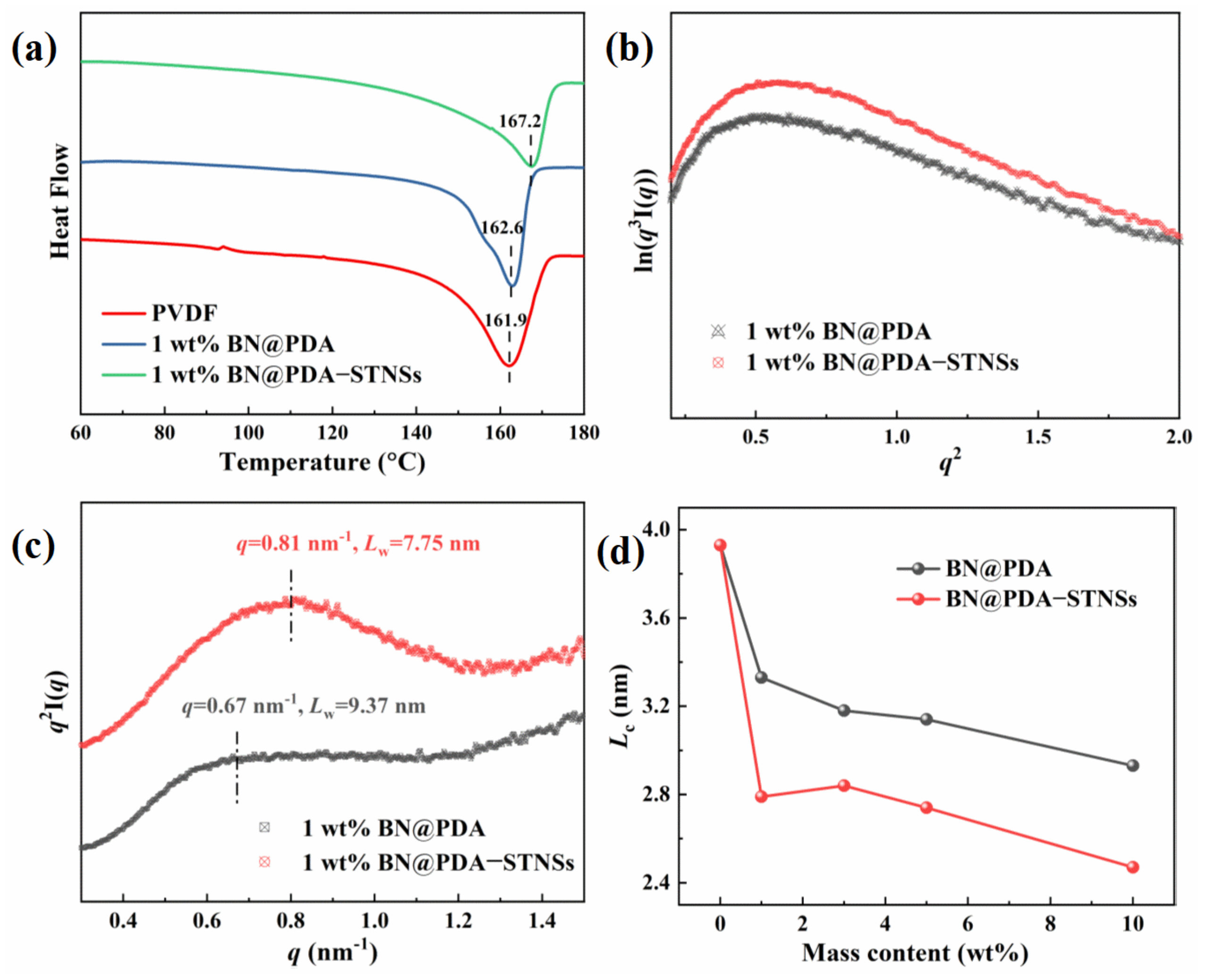
The crystalline behavior of all samples was investigated by DSC analysis (Figure 4a and Figure S10). It can be observed that the introduction of the BN@PDA or BN@PDA−STNSs multiphase fillers apparently increased the melting temperature (Tm) of PVDF. The pure PVDF exhibits a Tm of 162.2 °C, whereas the Tm values increase to 163.1 and 163.6 °C for the 1 wt% PVDF/BN@PDA and PVDF/BN@PDA−STNSs, respectively. Compared with pure PVDF and binary composites, the ternary composites show higher Tm, which may be ascribed to the enhanced interaction (hydrogen bonding) within the composites. The crystallinity (Xc) was calculated using Equation (2):
where ∆Hm−100% is the melting enthalpy of 100% crystalline PVDF (104.5 J/g). As shown in Figure 4a and Table S1, the Xc decreased from 41.8% to 35.6% for PVDF and 35.9% for the composites with 1 wt% BN@PDA and BN@PDA−STNSs, respectively. The decreased Xc is mainly attributed to the strong interaction at the interface, which can limit the growth of PVDF crystal [31].
Small angle X-ray scattering (SAXS) was used to characterize the microstructure of PVDF, PVDF/BN@PDA, and PVDF/BN@PDA−STNSs composites. Figure 4b and Figure S11 show the Porod curves of all samples, and all Porod curves show a negative deviation, which indicates the existence of the interfaces in composites [32,33]. It is well known that the lamellae and amorphous regions are ordered stacked within the spherulites. The long period (Lw) is calculated using Equation (3):
where qmax is the maximum scattering strength of SAXS profiles. The Lorentz corrected SAXS profiles of PVDF, PVDF/BN@PDA, and PVDF/BN@PDA−STNSs composites are shown in Figure 4c and Figure S12. Notably, the Lw decreases from 9.37 nm for 1 wt% binary composites to 7.75 nm for the 1 wt% ternary composite. The decreased Lw value of ternary composite means that the micro-structure of the composites was much denser than that of the PVDF and PVDF/BN@PDA composites. The thickness of the crystalline lamella region (Lc) was calculated using Equation (4):
where Xc is the crystallinity of the sample. The amorphous lamella region (La) was calculated using Equation (5):
The Lc and La of pure PVDF, PVDF/BN@PDA, and PVDF/BN@PDA−STNSs composites are shown in Figure S13. The composites all possessed decreased Lc, which is beneficial in promoting the reversal of dipoles within ferroelectric crystalline domains and thereby decrease the hysteresis loss. Compared with the PVDF/BN@PDA composites, the ternary composites showed a lower value of Lc (Figure 4d), which may be ascribed to the increased F(β) of PVDF/BN@PDA−STNSs composites [34].
3.3. Dielectric Properties of the Composites
For dielectric capacitors, high permittivity is one of the crucial characteristic needed for their energy storage performance. The frequency dependence of permittivity (εr) and dielectric loss tangent (tanδ) of two sets of composites tested at room temperature are shown in Figure 5. As shown in Figure 5a, the introduction of BN@PDA into the PVDF matrix results in decreased permittivity at 100 Hz from 9.2 to 8.0 because of the lower permittivity of BN@PDA (~4) than that of PVDF matrix (~8). Correspondingly, the dielectric loss tangent of PVDF/BN@PDA composites was also reduced (Figure 5b). The PVDF/BN@PDA composites possessed decreased dielectric loss tangent at low frequency, which could be ascribed to the depressed conduction loss and interface polarization loss. With the incorporation of STNSs into PVDF/BN@PDA binary composites, the permittivity of ternary composites increased significantly, as shown in Figure 5c. For example, the ternary composite with 1 wt% BN@PDA exhibited the highest εr of 13.9 at 1 Hz, which is 26.4% higher than that of pure PVDF (~11.0). With the increase in BN@PDA content, the permittivity of ternary composites increases first, and then decreases. Figure 5d shows dielectric loss tangent as a function of frequency for PVDF/BN@PDA−STNSs composites. When the frequency was greater than 3 Hz, the dielectric loss tangent of all ternary composites was lower than that of pure PVDF. The interfacial polarization occurs mainly in the low frequency region due to the long relaxation time. Therefore, the improved permittivity and dielectric loss tangent of the ternary composites are mainly attributed to the enhanced interface polarization. In addition, the increased concentration of electroactive β phase F(β) and the high permittivity of STNSs might be the reasons for the permittivity enhancement. As the frequency increased further, the dielectric loss tangent of the ternary composites at the same frequency was lower than that of pure PVDF, which may be attributed to the reduction in the crystalline lamella region (Lc).
To further study the effect of BN@PDA and STNSs on the dielectric relaxation of ternary composites, the relaxation imaginary electric modulus (M″) of the ternary composites was measured, as shown in Figure S14. The electric modulus (M*) can be calculated using Equation (6):
where M″ can be used to analyze the relaxation in dielectric performance without the electrical conduction effect. The interfacial polarization relaxation peak that usually occurs below 1 Hz is not clearly displayed due to the instrument measurement range. Nevertheless, the trough of spectrum shifts towards a higher frequency with the increase in filler content, BN@PDA−STNSs indicating the increasing influence of interfacial polarization. These results are in good agreement with the dielectric properties analysis above.
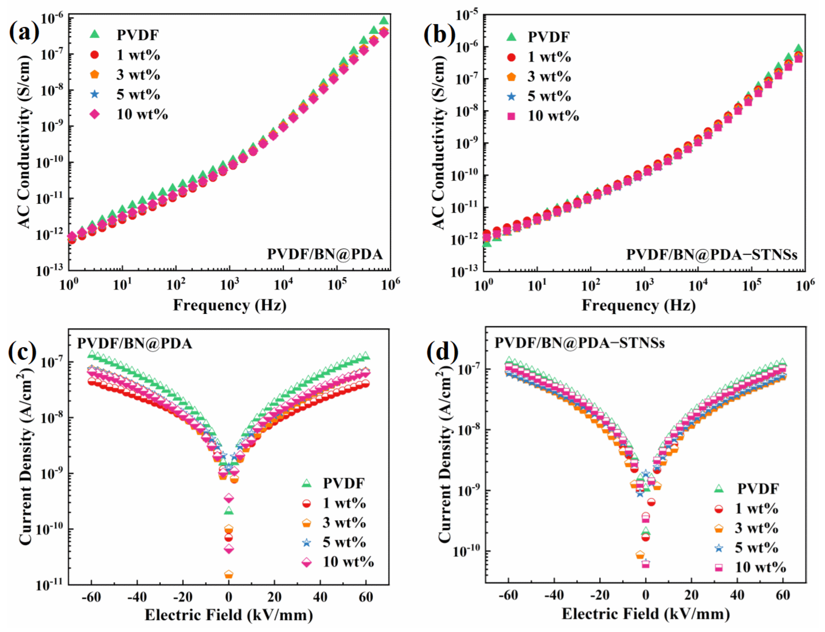
To study the effect of the STNSs on the conduction of ternary composites, the AC conduction and leakage current density of pure PVDF, PVDF/BN@PDA, and PVDF/composites were tested. Figure 6a,b show the frequency-dependent AC conductivity of two series of composites. The AC conductivity of both sets of composites possessed a strong frequency dependence, suggesting the outstanding insulating performance of the composites. The addition of BN@PDA with excellent insulating performance lead to continuously depressed AC conductivity in PVDF/BN@PDA composites. The introduction of STNSs caused the increased AC conductivity of ternary composites, especially at a low frequency (1 Hz to 103 Hz). The leakage current density of two series of composites is shown in Figure 6c,d. The PVDF/BN@PDA composites possessed significantly decreased leakage current density, which indicates that the BN@PDA sheets have the function of impeding the movement of charges [35]. With the incorporation of the STNSs into PVDF/BN@PDA binary composites, the leakage current density of ternary composites increased. It is worth noting that the leakage current density of ternary composites was lower than that of pure PVDF, which could be attributed to the BN@PDA with high insulating performance. The above results are consistent with the dielectric loss tangent results.
3.4. Breakdown and Energy Storage Properties of the Composites
Apart from permittivity, the breakdown strength also plays an important role in improving the energy storage density of composites [36]. The Weibull distribution was used to analyze the breakdown strength of all composites, which is described by Equation (7):
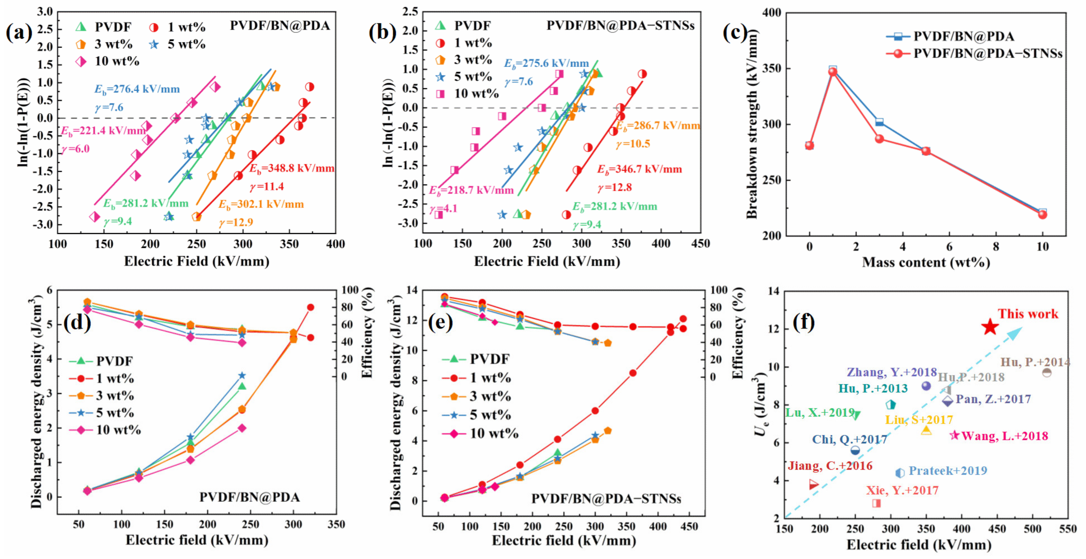
where P(E) is the cumulative breakdown probability, E means the measured breakdown strength, Eb is the characteristic breakdown strength, and γ is the shape parameter evaluating the scatter of the measured breakdown strength values. A higher γ value means a higher level of dielectric reliability [37]. Figure 7a,b show the Weibull distribution of Eb of PVDF/BN@PDA and PVDF/BN@PDA−STNSs composites. The characteristic breakdown strength of all the samples is summarized in Figure 7c. With BN@PDA contents increasing, the Eb of the PVDF/BN@PDA composites first increases, and then decreases. The Eb of PVDF/BN@PDA−STNSs composites possess a similar tendency. Interestingly, the Eb of the ternary composites introduced by STNSs did not significantly decrease, presenting a value similar to that of the binary composite. For example, the Eb values of the 1 wt% PVDF/BN@PDA and PVDF/BN@PDA−STNSs composites were 348.8 and 346.7 kV/mm, respectively, which is 24.0% and 23.3% higher than that of pure PVDF (281.2 kV/mm). Based on the above analysis, STNSs were introduced into PVDF/BN@PDA binary composites and significantly improved the permittivity of binary composites, whereas the breakdown strength of binary composites did not deteriorate significantly.
The unipolar polarization-electric field (P-E) loops of pure PVDF, PVDF/BN@PDA, and PVDF/BN@PDA−STNSs composites are illustrated in Figure S15. The discharged energy density (Ue) and efficiency (η) of pure PVDF and of the composites were calculated from the P-E loops and displayed in Figure 7d,e [38]. The Ue of the binary composite filled with 1 wt% BN@PDA was significantly increased (5.5 J/cm3), which could be attributed to the increased Eb of the binary composites due to the introduction of BN@PDA. Compared with pure PVDF, the Ue of the binary composite obviously decreased at the same applied electric field because of the decreased permittivity and maximal polarization. The introduction of STNSs caused significantly increased permittivity and maximal polarization of ternary composites, whereas the Eb did not obviously decrease compared with the binary composites. The PVDF/BN@PDA−STNSs composites possessed improved permittivity and characteristic breakdown strength, yielding the dramatically lifted discharged energy density Ue. In particular, the Ue of the 1 wt% ternary composite was as high as 12.1 J/cm3 at 440 kV/mm, which is 278.1% higher than that of pure PVDF (3.2 J/cm3 at 240 kV/mm). The 1 wt% ternary composite showed higher η compared with pure PVDF, which is ascribed to suppressed leakage current density.
For comparison, the the Ue and Eb of related state-of-the-art composite films filled with different fillers in recent work are summarized in Figure 7f. The samples located below the blue diagonal line always show excellent Ue, and the ones located above the blue diagonal line display high Eb. The expected performance of composite is shown by a blue arrow. The 1 wt% PVDF/BN@PDA−STNSs composite in this work possessed a combination of outstanding Ue and high Eb, which is superior to the previously reported dielectric materials.
A finite element simulation was performed to investigate the distribution of the electrical potential, electric field, and polarization in the composites. As shown in Figure 8a1,a2, due to the applied electric field from top to bottom, the electric potential gradually decreased from top to bottom. Due to the large difference of permittivity between the STNSs and PVDF matrix, the isopotential line fluctuated greatly when passing through STNSs. Figure 8b1,b2 show cross-sectional images of local electrical field distribution for the PVDF/BN@PDA and PVDF/BN@PDA−STNSs composites. The legend with the unit of kV/mm refers to the redistributed local electric field strength in the composites. The BN@PDA sheets with good insulation bore more electric field, which is beneficial in improving the breakdown strength of the composites. STNSs doping brought a small number of weak electric field distortion points, resulting in a slight reduction in the breakdown field strength of the ternary composites compared to that of the binary composites. Figure 8c1,c2 are the sectional images of the local polarization intensity distribution of the binary and ternary composites, respectively. As can be seen from the figure, in addition to the high polarization intensity region at the interface between the BN@PDA and PVDF matrix, STNSs doping brought a higher interfacial polarization region to the ternary composites. For example, the polarization intensity on the STNSs inside the composite was 1030.5 μC/m2.
4. Conclusions
In summary, the BN@PDA and STNSs as synergistic dual-fillers in PVDF-based composites have simultaneously enhanced permittivity and breakdown strength. Therefore, the PVDF/BN@PDA−STNSs possess improved discharged energy density. The excellent Ue was obtained by the elegant combination of STNSs and BN@PDA fillers with complementary functionalities. The increased permittivity of the PVDF/BN@PDA−STNSs composites mainly comes from the STNSs themselves, improved interfacial polarization, and contents of β phase PVDF F(β). The significantly enhanced Eb could be ascribed to the suppressed leakage current density induced by BN@PDA. The method described in this paper demonstrates the advantages of facile preparation and thus provides a general design paradigm for combining complementary structured fillers in polymer composites to improve their comprehensive properties.
Supplementary Materials
The following supporting information can be downloaded at: https://www.mdpi.com/article/10.3390/ma15134370/s1, Figure S1: Schematic illustration of synthesizing the PVDF/BN@PDA−STNSs composites; Figure S2: (a) Low power TEM image and (b) high power TEM image of 2D BN@PDA sheets; Figure S3: The thickness distribution of 2D BN@PDA sheets; Figure S4: The EDS spectrum of BN@PDA; Figure S5: The EDS spectrum of STNSs; Figure S6: Cross-section morphology of the (a) 3 wt% and (b) 10 wt% PVDF/BN@PDA composite; Figure S7:(a) Cross-section morphology and (b) mapping of 3 wt% PVDF/BN−STNSs composite; Figure S8: The XRD patterns of (a) PVDF/BN@PDA and (b) PVDF/BN@PDA−STNSs composites; Figure S9: FTIR spectra of (a) PVDF/BN@PDA and (b) PVDF/BN@PDA−STNSs composites; Figure S10: The DSC endothermic curves of (a) PVDF/BN@PDA and (b) PVDF/BN@PDA−STNSs composites; Figure S11: Porod curves of (a) PVDF/BN@PDA and (b) PVDF/BN@PDA−STNSs composites; Figure S12: Lorentz corrected SAXS profiles of (a) PVDF/BN@PDA and (b) PVDF/BN@PDA−STNSs composites; Figure S13: The Lc and La of (a) PVDF/BN@PDA and (b) PVDF/BN@PDA−STNSs composites; Figure S14: M” of the PVDF/BN@PDA−STNSs ternary composites; Figure S15: Hysteresis loops of pure PVDF, PVDF/BN@PDA and PVDF/BN@PDA−STNSs composites; Table S1: DSC results and F(β) of the composites.
Author Contributions
Conceptualization, J.Y. and X.L.; methodology, Y.F.; software, D.Y.; validation, J.L., Y.L. and H.Z.; writing—original draft preparation, C.Z.; writing—review and editing, C.Z. All authors have read and agreed to the published version of the manuscript.
Funding
This research was funded by National Natural Science Foundation of China (grant numbers 51777047) and Natural Science Foundation of Heilongjiang Province of China (No. YQ2021E036).
Institutional Review Board Statement
Not applicable.
Informed Consent Statement
Not applicable.
Data Availability Statement
Not applicable.
Acknowledgments
The authors wish to thank the Beijing Synchrotron Radiation Facility (BSRF) for its facility support.
Conflicts of Interest
The authors declare no conflict of interest.
References
- Li, H.; Ai, D.; Ren, L.; Yao, B.; Han, Z.; Shen, Z.; Wang, J.; Chen, L.Q.; Wang, Q. Scalable Polymer Nanocomposites with Record High-Temperature Capacitive Performance Enabled by Rationally Designed Nanostructured Inorganic Fillers. Adv. Mater. 2019, 31, e1900875. [Google Scholar] [CrossRef]
- Liu, X.; Ji, T.; Guo, H.; Wang, H.; Li, J.; Liu, H.; Shen, Z. Effects of Crystallinity and Defects of Layered Carbon Materials on Potassium Storage: A Review and Prediction. Electrochem. Energy Rev. 2022, 5, 401–433. [Google Scholar] [CrossRef]
- Callegari, D.; Colombi, S.; Nitti, A.; Simari, C.; Nicotera, I.; Ferrara, C.; Mustarelli, P.; Pasini, D.; Quartarone, E. Autonomous Self-Healing Strategy for Stable Sodium-Ion Battery: A Case Study of Black Phosphorus Anodes. ACS Appl. Mater. Interfaces 2021, 13, 13170–13182. [Google Scholar] [CrossRef]
- Pasini, D.; Klopp, J.M.; Fréchet, J.M. Design, synthesis, and characterization of carbon-rich cyclopolymers for 193 nm microlithography. Chem. Mater. 2001, 13, 4136–4146. [Google Scholar] [CrossRef]
- Shen, Y.; Hu, Y.; Chen, W.; Wang, J.; Guan, Y.; Du, J.; Zhang, X.; Ma, J.; Li, M.; Lin, Y.; et al. Modulation of topological structure induces ultrahigh energy density of graphene/Ba0.6Sr0.4TiO3 nanofiber/polymer nanocomposites. Nano Energy 2015, 18, 176–186. [Google Scholar] [CrossRef]
- Li, Q.; Chen, L.; Gadinski, M.R.; Zhang, S.; Zhang, G.; Li, U.; Iagodkine, E.; Haque, A.; Chen, L.Q.; Jackson, N.; et al. Flexible high-temperature dielectric materials from polymer nanocomposites. Nature 2015, 523, 576–579. [Google Scholar] [CrossRef]
- Zhang, Y.; Zhang, C.; Feng, Y.; Zhang, T.; Chen, Q.; Chi, Q.; Liu, L.; Li, G.; Cui, Y.; Wang, X.; et al. Excellent energy storage performance and thermal property of polymer-based composite induced by multifunctional one-dimensional nanofibers oriented in-plane direction. Nano Energy 2019, 56, 138–150. [Google Scholar] [CrossRef]
- Yuan, J. Percolation of carbon nanomaterials for high-k polymer nanocomposites. Chin. Chem. Lett. 2017, 28, 2036–2044. [Google Scholar] [CrossRef]
- Huang, X.; Jiang, P. Core-shell structured high-k polymer nanocomposites for energy storage and dielectric applications. Adv. Mater. 2015, 27, 546–554. [Google Scholar] [CrossRef]
- Cui, Y.; Zhang, T.; Feng, Y.; Zhang, C.; Chi, Q.; Zhang, Y.; Chen, Q.; Wang, X.; Lei, Q. Excellent energy storage density and efficiency in blend polymer-based composites by design of core-shell structured inorganic fibers and sandwich structured films. Compos. Part B Eng. 2019, 177, 107429. [Google Scholar] [CrossRef]
- Lin, X.; Wang, J.; Chu, Z.; Liu, D.; Guo, T.; Yang, L.; Huang, Z.; Mu, S.; Li, S. The optimization of hydrothermal process of MoS2 nanosheets and their good microwave absorption performances. Chin. Chem. Lett. 2020, 31, 1124–1128. [Google Scholar] [CrossRef]
- Mao, L.; Cai, X.-Y.; Zhu, M.-S. Hierarchically 1D CdS decorated on 2D perovskite-type La2Ti2O7 nanosheet hybrids with enhanced photocatalytic performance. Rare Met. 2020, 40, 1067–1076. [Google Scholar] [CrossRef]
- Shi, F.; Sun, J.; Wang, J.; Liu, M.; Wang, S.; Cao, X.; Yan, Z.; Li, Y.; Nunes, S.P. Exploration of the Synergy Between 2D Nanosheets and a Non-2D Filler in Mixed Matrix Membranes for Gas Separation. Front. Chem. 2020, 8, 58. [Google Scholar] [CrossRef]
- Xie, Y.; Wang, J.; Yu, Y.; Jiang, W.; Zhang, Z. Enhancing breakdown strength and energy storage performance of PVDF-based nanocomposites by adding exfoliated boron nitride. Appl. Surf. Sci. 2018, 440, 1150–1158. [Google Scholar] [CrossRef]
- Ai, D.; Li, H.; Zhou, Y.; Ren, L.; Han, Z.; Yao, B.; Zhou, W.; Zhao, L.; Xu, J.; Wang, Q. Tuning Nanofillers in In Situ Prepared Polyimide Nanocomposites for High-Temperature Capacitive Energy Storage. Adv. Energy Mater. 2020, 10, 1903881. [Google Scholar] [CrossRef]
- Shi, C.; Liu, S.; Li, Y.; Zhao, J.; Huang, H. Enhanced mechanical and thermal properties of γ-allyloxymethyl 18-crown-6 and polyimide composites through hydrosilylation crosslinking. Chin. Chem. Lett. 2019, 30, 710–713. [Google Scholar] [CrossRef]
- Zhu, Y.; Zhu, Y.; Huang, X.; Chen, J.; Li, Q.; He, J.; Jiang, P. High Energy Density Polymer Dielectrics Interlayered by Assembled Boron Nitride Nanosheets. Adv. Energy Mater. 2019, 9, 1901826. [Google Scholar] [CrossRef]
- Feng, Y.; Zhou, Y.; Zhang, T.; Zhang, C.; Zhang, Y.; Zhang, Y.; Chen, Q.; Chi, Q. Ultrahigh discharge efficiency and excellent energy density in oriented core-shell nanofiber-polyetherimide composites. Energy Storage Mater. 2020, 25, 180–192. [Google Scholar] [CrossRef]
- Nitti, A.; Po, R.; Bianchi, G.; Pasini, D. Direct Arylation Strategies in the Synthesis of pi-Extended Monomers for Organic Polymeric Solar Cells. Molecules 2016, 22, 21. [Google Scholar] [CrossRef] [Green Version]
- Pasini, D.; Low, E.; Fréchet, J. Novel Design of Carbon-Rich Polymers for 193 nm Microlithography: Adamantane-Containing Cyclopolymers. Adv. Mater. 2000, 12, 347–351. [Google Scholar] [CrossRef]
- Ma, R.-T.; Shang, H.-Y.; Wang, X.; Jiang, D. Dielectric, magnetic and microwave absorbing properties of polyaniline-Co0.7Cr0.1Zn0.2Fe2O4 composites. Rare Met. 2015, 36, 118–122. [Google Scholar] [CrossRef]
- Zhu, C.; Yin, J.; Li, J.; Li, Y.; Zhao, H.; Yue, D.; Pan, L.; Wang, J.; Feng, Y.; Liu, X. Enhanced energy storage of polyvinylidene fluoride-based nanocomposites induced by high aspect ratio titania nanosheets. J. Appl. Polym. Sci. 2021, 138, 50244. [Google Scholar] [CrossRef]
- Hou, J.; Zheng, Y.; Su, Y.; Zhang, W.; Hoshide, T.; Xia, F.; Jie, J.; Li, Q.; Zhao, Z.; Ma, R.; et al. Macroscopic and Strong Ribbons of Functionality-Rich Metal Oxides from Highly Ordered Assembly of Unilamellar Sheets. J. Am. Chem. Soc. 2015, 137, 13200–13208. [Google Scholar] [CrossRef] [PubMed]
- Zhu, C.; Liu, X.; Feng, Y.; Li, J.; Li, Y.; Zhao, H.; Yue, D.; Yin, J. Adjusting the energy gap and interface effect of titania nanosheets synergistically enhances the energy storage performance of PVDF based composites. J. Mater. Chem. C 2022, 10, 2128–2138. [Google Scholar] [CrossRef]
- Song, Y.; Shen, Y.; Liu, H.; Lin, Y.; Li, M.; Nan, C.-W. Improving the dielectric constants and breakdown strength of polymer composites: Effects of the shape of the BaTiO3 nanoinclusions, surface modification and polymer matrix. J. Mater. Chem. 2012, 22, 16491. [Google Scholar] [CrossRef]
- Xie, Y.; Jiang, W.; Fu, T.; Liu, J.; Zhang, Z.; Wang, S. Achieving High Energy Density and Low Loss in PVDF/BST Nanodielectrics with Enhanced Structural Homogeneity. ACS Appl. Mater. Interfaces 2018, 10, 29038–29047. [Google Scholar] [CrossRef] [PubMed]
- Yuan, D.; Li, Z.; Thitsartarn, W.; Fan, X.; Sun, J.; Li, H.; He, C. β phase PVDF-hfp induced by mesoporous SiO2 nanorods: Synthesis and formation mechanism. J. Mater. Chem. C 2015, 3, 3708–3713. [Google Scholar] [CrossRef]
- Liu, X.; Nie, T.; Li, Y.; Li, J.; Wang, T.; Feng, Y.; Yue, D.; Yin, J. Nanocomposites induced by two-dimensional titanium carbide nanosheets for highly efficient energy storage. Polym. Test. 2020, 89, 106712. [Google Scholar] [CrossRef]
- Thakur, P.; Kool, A.; Hoque, N.A.; Bagchi, B.; Khatun, F.; Biswas, P.; Brahma, D.; Roy, S.; Banerjee, S.; Das, S. Superior performances of in situ synthesized ZnO/PVDF thin film based self-poled piezoelectric nanogenerator and self-charged photo-power bank with high durability. Nano Energy 2018, 44, 456–467. [Google Scholar] [CrossRef]
- Yue, D.; Feng, Y.; Liu, X.X.; Yin, J.H.; Zhang, W.C.; Guo, H.; Su, B.; Lei, Q.Q. Prediction of Energy Storage Performance in Polymer Composites Using High-Throughput Stochastic Breakdown Simulation and Machine Learning. Adv. Sci. 2022, e2105773. [Google Scholar] [CrossRef] [PubMed]
- Sharma, M.; Madras, G.; Bose, S. Contrasting Effects of Graphene Oxide and Poly(ethylenimine) on the Polymorphism in Poly(vinylidene fluoride). Cryst. Growth Des. 2015, 15, 3345–3355. [Google Scholar] [CrossRef]
- Zhao, H.; Yang, C.; Li, N.; Yin, J.; Feng, Y.; Liu, Y.; Li, J.; Li, Y.; Yue, D.; Zhu, C.; et al. Electrical and mechanical properties of polyimide composite films reinforced by ultralong titanate nanotubes. Surf. Coat. Technol. 2019, 360, 13–19. [Google Scholar] [CrossRef]
- Zhang, Y.-Y.; Min, Y.; Wang, G.-L.; Wang, Z.-F.; Liu, J.-L.; Luo, Z.-W.; Zhang, M. Design and properties of calcium copper titanate/poly(dimethyl siloxane) dielectric elastomer composites. Rare Met. 2019, 40, 2627–2632. [Google Scholar] [CrossRef]
- Sharma, M.; Madras, G.; Bose, S. Cooperativity and Structural Relaxations in PVDF/PMMA Blends in the Presence of MWNTs: An Assessment through SAXS and Dielectric Spectroscopy. Macromolecules 2014, 47, 1392–1402. [Google Scholar] [CrossRef]
- Wu, C.-P.; Xie, K.-X.; He, J.-P.; Wang, Q.-P.; Ma, J.-M.; Yang, S.; Wang, Q.-H. SnO2 quantum dots modified N-doped carbon as high-performance anode for lithium ion batteries by enhanced pseudocapacitance. Rare Met. 2020, 40, 48–56. [Google Scholar] [CrossRef]
- Luo, S.; Yu, J.; Yu, S.; Sun, R.; Cao, L.; Liao, W.-H.; Wong, C.-P. Significantly Enhanced Electrostatic Energy Storage Performance of Flexible Polymer Composites by Introducing Highly Insulating-Ferroelectric Microhybrids as Fillers. Adv. Energy Mater. 2019, 9, 1803204. [Google Scholar] [CrossRef]
- Li, J.; Liu, X.; Feng, Y.; Yin, J. Recent progress in polymer/two-dimensional nanosheets composites with novel performances. Prog. Polym. Sci. 2022, 126, 101505. [Google Scholar] [CrossRef]
- Li, Y.; Yin, J.; Feng, Y.; Li, J.; Zhao, H.; Zhu, C.; Yue, D.; Liu, Y.; Su, B.; Liu, X. Metal-organic Framework/Polyimide composite with enhanced breakdown strength for flexible capacitor. Chem. Eng. J. 2022, 429, 132228. [Google Scholar] [CrossRef]
- Jiang, C.; Zhang, D.; Zhou, K.; Zhou, X.; Luo, H.; Abrahams, I. Significantly enhanced energy storage density of sandwich-structured (Na0.5Bi0.5)0.93Ba0.07TiO3/P (VDF–HFP) composites induced by PVP-modified two-dimensional platelets. J. Mater. Chem. A 2016, 4, 18050–18059. [Google Scholar] [CrossRef]
- Xie, Y.; Yu, Y.; Feng, Y.; Jiang, W.; Zhang, Z. Fabrication of Stretchable Nanocomposites with High Energy Density and Low Loss from Cross-Linked PVDF Filled with Poly(dopamine) Encapsulated BaTiO3. ACS Appl. Mater. Interfaces 2017, 9, 2995–3005. [Google Scholar] [CrossRef] [PubMed]
- Lu, X.; Zhang, L.; Tong, Y.; Cheng, Z.Y. BST-P(VDF-CTFE) nanocomposite films with high dielectric constant, low dielectric loss, and high energy-storage density. Compos. Part B Eng. 2019, 168, 34–43. [Google Scholar] [CrossRef]
- Chi, Q.; Ma, T.; Zhang, Y.; Cui, Y.; Zhang, C.; Lin, J.; Wang, X.; Lei, Q. Significantly enhanced energy storage density for poly(vinylidene fluoride) composites by induced PDA-coated 0.5Ba(Zr0.2Ti0.8)O3–0.5(Ba0.7Ca0.3)TiO3 nanofibers. J. Mater. Chem. A 2017, 5, 16757–16766. [Google Scholar] [CrossRef]
- Hu, P.; Wang, J.; Shen, Y.; Guan, Y.; Lin, Y.; Nan, C.-W. Highly enhanced energy density induced by hetero-interface in sandwich-structured polymer nanocomposites. J. Mater. Chem. A 2013, 1, 12321–12326. [Google Scholar] [CrossRef]
- Liu, S.; Wang, J.; Wang, J.; Shen, B.; Zhai, J.; Guo, C.; Zhou, J. Core-shell structured BaTiO3@SiO2 nanofibers for poly(vinylidene fluoride) nanocomposites with high discharged energy. Mater. Lett. 2017, 189, 176–179. [Google Scholar] [CrossRef]
- Zhang, Y.; Zhang, T.; Liu, L.; Chi, Q.; Zhang, C.; Chen, Q.; Cui, Y.; Wang, X.; Lei, Q. Sandwich-structured PVDF-based composite incorporated with hybrid Fe3O4@ BN nanosheets for excellent dielectric properties and energy storage performance. J. Phys. Chem. C 2018, 122, 1500–1512. [Google Scholar] [CrossRef]
- Hu, P.; Jia, Z.; Shen, Z.; Wang, P.; Liu, X. High dielectric constant and energy density induced by the tunable TiO2 interfacial buffer layer in PVDF nanocomposite contained with core–shell structured TiO2@BaTiO3 nanoparticles. Appl. Surf. Sci. 2018, 441, 824–831. [Google Scholar] [CrossRef]
- Pan, Z.; Yao, L.; Zhai, J.; Wang, H.; Shen, B. Ultrafast Discharge and Enhanced Energy Density of Polymer Nanocomposites Loaded with 0.5(Ba0.7Ca0.3)TiO3-0.5Ba(Zr0.2Ti0.8)O3 One-Dimensional Nanofibers. ACS Appl. Mater. Interfaces 2017, 9, 14337–14346. [Google Scholar] [CrossRef] [PubMed]
- Wang, L.; Huang, X.; Zhu, Y.; Jiang, P. Enhancing electrical energy storage capability of dielectric polymer nanocomposites via the room temperature Coulomb blockade effect of ultra-small platinum nanoparticles. Phys. Chem. Chem. Phys. PCCP 2018, 20, 5001–5011. [Google Scholar] [CrossRef]
- Prateek; Bhunia, R.; Siddiqui, S.; Garg, A.; Gupta, R.K. Significantly Enhanced Energy Density by Tailoring the Interface in Hierarchically Structured TiO2-BaTiO3-TiO2 Nanofillers in PVDF-Based Thin-Film Polymer Nanocomposites. ACS Appl. Mater. Interfaces 2019, 11, 14329–14339. [Google Scholar] [CrossRef] [PubMed]
- Hu, P.; Shen, Y.; Guan, Y.; Zhang, X.; Lin, Y.; Zhang, Q.; Nan, C.W. Topological-structure modulated polymer nanocomposites exhibiting highly enhanced dielectric strength and energy density. Adv. Funct. Mater. 2014, 24, 3172–3178. [Google Scholar] [CrossRef]
Figure 1.
The SEM images of (a) BN@PDA and (b) STNSs. The diameter distribution of (c) BN@PDA and (d) STNSs. (e) The XRD patterns and (f) FTIR spectra of BN@PDA and STNSs.
Figure 1.
The SEM images of (a) BN@PDA and (b) STNSs. The diameter distribution of (c) BN@PDA and (d) STNSs. (e) The XRD patterns and (f) FTIR spectra of BN@PDA and STNSs.

Figure 2.
(a) The cross-section SEM images of the composites filled with 1 wt% BN@PDA and 0.5 wt% STNSs. (b) The enlarged area of (a).
Figure 2.
(a) The cross-section SEM images of the composites filled with 1 wt% BN@PDA and 0.5 wt% STNSs. (b) The enlarged area of (a).

Figure 3.
(a) The XRD patterns of pure PVDF, PVDF/BN@PDA, and PVDF/BN@PDA−STNSs composites. FTIR spectra of (b) the PVDF/BN@PDA and (c) PVDF/BN@PDA−STNSs composites. (d) F(β) of pure PVDF, PVDF/BN@PDA, and PVDF/BN@PDA−STNSs composites.
Figure 3.
(a) The XRD patterns of pure PVDF, PVDF/BN@PDA, and PVDF/BN@PDA−STNSs composites. FTIR spectra of (b) the PVDF/BN@PDA and (c) PVDF/BN@PDA−STNSs composites. (d) F(β) of pure PVDF, PVDF/BN@PDA, and PVDF/BN@PDA−STNSs composites.

Figure 4.
(a) The DSC endothermic curves; (b) Porod curves; (c) Lorentz corrected SAXS profiles; and (d) Lc of pure PVDF, PVDF/BN@PDA, and PVDF/BN@PDA−STNSs composites.
Figure 4.
(a) The DSC endothermic curves; (b) Porod curves; (c) Lorentz corrected SAXS profiles; and (d) Lc of pure PVDF, PVDF/BN@PDA, and PVDF/BN@PDA−STNSs composites.

Figure 5.
Dielectric permittivity of (a) PVDF/BN@PDA and (c) PVDF/BN@PDA−STNSs composites. Dielectric loss tangent of (b) PVDF/BN@PDA and (d) PVDF/BN@PDA−STNSs composites.
Figure 5.
Dielectric permittivity of (a) PVDF/BN@PDA and (c) PVDF/BN@PDA−STNSs composites. Dielectric loss tangent of (b) PVDF/BN@PDA and (d) PVDF/BN@PDA−STNSs composites.

Figure 6.
The AC conductivity of (a) PVDF/BN@PDA and (b) PVDF/BN@PDA−STNSs composites. The current density at 60 kV/mm of (c) PVDF/BN@PDA and (d) PVDF/BN@PDA−STNSs composites.
Figure 6.
The AC conductivity of (a) PVDF/BN@PDA and (b) PVDF/BN@PDA−STNSs composites. The current density at 60 kV/mm of (c) PVDF/BN@PDA and (d) PVDF/BN@PDA−STNSs composites.

Figure 7.
Two-parameter Weibull distribution plots of (a) PVDF/BN@PDA and (b) PVDF/BN@PDA−STNSs composites. (c) Variation of characteristic breakdown strength of PVDF/BN@PDA and PVDF/BN@PDA−STNSs composites with increasing filler content. Discharged energy density (Ue) and efficiency (η) of (d) PVDF/BN@PDA and (e) PVDF/BN@PDA−STNSs. (f) Comparison of Ue and Eb of related state-of-the-art composites filled with different fillers, respectively [39,40,41,42,43,44,45,46,47,48,49,50].

Figure 8.
Finite element simulation of electrical potential of (a1) PVDF/BN@PDA and (a2) PVDF/BN@PDA−STNSs composites. Finite element simulation of local electric field of (b1) PVDF/BN@PDA and (b2) PVDF/BN@PDA−STNSs composites, and local polarization distribution of (c1) PVDF/BN@PDA and (c2) PVDF/BN@PDA−STNSs composites.

Publisher’s Note: MDPI stays neutral with regard to jurisdictional claims in published maps and institutional affiliations. |
© 2022 by the authors. Licensee MDPI, Basel, Switzerland. This article is an open access article distributed under the terms and conditions of the Creative Commons Attribution (CC BY) license (https://creativecommons.org/licenses/by/4.0/).
Share and Cite
MDPI and ACS Style
Zhu, C.; Yin, J.; Feng, Y.; Li, J.; Li, Y.; Zhao, H.; Yue, D.; Liu, X. Enhanced Energy Storage Performance of PVDF-Based Composites Using BN@PDA Sheets and Titania Nanosheets. Materials 2022, 15, 4370. https://doi.org/10.3390/ma15134370
AMA Style
Zhu C, Yin J, Feng Y, Li J, Li Y, Zhao H, Yue D, Liu X. Enhanced Energy Storage Performance of PVDF-Based Composites Using BN@PDA Sheets and Titania Nanosheets. Materials. 2022; 15(13):4370. https://doi.org/10.3390/ma15134370
Chicago/Turabian StyleZhu, Congcong, Jinghua Yin, Yu Feng, Jialong Li, Yanpeng Li, He Zhao, Dong Yue, and Xiaoxu Liu. 2022. "Enhanced Energy Storage Performance of PVDF-Based Composites Using BN@PDA Sheets and Titania Nanosheets" Materials 15, no. 13: 4370. https://doi.org/10.3390/ma15134370
Note that from the first issue of 2016, this journal uses article numbers instead of page numbers. See further details here.