Article

Experimental Investigation of Thrust Force, Delamination and Surface Roughness in Drilling Hybrid Structural Composites

by
Vigneshwaran Shanmugam
1,
Uthayakumar Marimuthu
2,3,*,
Sundarakannan Rajendran
2,
Arumugaprabu Veerasimman
2,
Adamkhan Mahaboob Basha
2,
Mohd Shukry Bin Abdul Majid
3,
Rasoul Esmaeely Neisiany
4,
Michael Försth
5,
Gabriel Sas
5,
Nima Razavi
6,* and
Oisik Das
5,*
1
Department of Mechanical Engineering, Saveetha Institute of Medical and Technical Sciences, Saveetha School of Engineering, Chennai 602105, India
2
Department of Mechanical Engineering, Kalasalingam Academy of Research and Education, Krishnankoil 626126, India
3
Faculty of Mechanical Engineering Technology, Universiti Malaysia Perlis (UniMAP), Arau 02600, Perlis, Malaysia
4
Department of Materials and Polymer Engineering, Faculty of Engineering, Hakim Sabzevari University, Sabzevar 9617976487, Iran
5
Structural and Fire Engineering Division, Department of Civil, Environmental and Natural Resources Engineering, Luleå University of Technology, 97187 Luleå, Sweden
6
Department of Mechanical and Industrial Engineering, Norwegian University of Science and Technology, 7491 Trondheim, Norway
*
Authors to whom correspondence should be addressed.
Materials 2021, 14(16), 4468; https://doi.org/10.3390/ma14164468
Submission received: 7 July 2021 / Revised: 2 August 2021 / Accepted: 3 August 2021 / Published: 9 August 2021
(This article belongs to the Section Polymeric Materials)

Abstract

:
Filled hybrid composites are widely used in various structural applications where machining is critical. Hence, it is essential to understand the performance of the fibre composites’ machining behaviour. As such, a new hybrid structural composite was fabricated with redmud as filler and sisal fibre as reinforcement in polyester matrix. The composite was then tested for its drilling performance. A comprehensive drilling experiment was conducted using Taguchi L27 orthogonal array. The effect of the drill tool point angle, the cutting speed, the feed rate on thrust force, delamination, and burr formation were analysed for producing quality holes. The significance of each parameter was analysed, and the experimental outcomes revealed some important findings in the context of the drilling behaviour of sisal fibre/polyester composites with redmud as a filler. Spindle speed contributed 39% in affecting the thrust force, while the feed rate had the maximum influence of ca. 38% in affecting delamination.

1. Introduction

Particle reinforced hybrid composites have become highly recommended materials in various structural applications due to their advanced engineering properties. These composites are gaining more attention in modern application—especially in many engineering structures and constructions—because of their light weight and increased strength over conventional materials [1,2,3]. The particle composites have increased stiffness, strength, and moisture-absorption stability, making them better candidates for structural applications [4,5,6,7]. However, machinability (e.g., drilling) of these structural composites is difficult because of their heterogeneous properties [8,9]. It is necessary to machine holes and slots in composites to create temporary joints with nuts and bolts. Loss of properties during machining/drilling reduces structural strength and lowers assembly tolerance that can be detrimental to long-term performance.
One of the main constraints that prevent these composites from widespread structural applications is the difficulty in machining [10]. In general, machining of fibre-reinforced composites produces higher delamination, which is unavoidable [11]. Reinforcement of particles in the composite may make machining more difficult, thus causing the tool to wear rapidly [12]. By controlling machining parameters, machining can be conducted with reduced delamination, surface roughness, and cutting forces [13]. The machining phenomenon of polymeric structural composites is different and more difficult than the process used for their metallic counterparts. During machining of fibre composites, the tool interacts with the fibre and matrix, which softens the matrix surface and results in fibre pullout, uncut fibres, delamination, and poor surface finish [14]. Considering the increasing structural application of these composites, the limitation in their machining performance should be envisaged in a detailed and systematic way for producing quality holes with reduced damage. Babu et al. [15] reported that delamination in fibre composites can be minimised by machining at lower feed and higher cutting speed. Chandramohan and Marimuthu [16] reported that thrust forces have no significant effect on lower feed and cutting speed. However, their investigation found that the thrust force was low at a high feed rate and cutting speed. Yallew et al. [17] reported that the tool point angle is an important factor in deciding the delamination and hole quality in natural fibre-reinforced composites and that the drilling quality of natural fibre composites can be increased through chemical treatment of fibre [18]. Athijayamani et al. [19] reported that the chemically treated fibre-reinforced composite exhibited better dimensional accuracy than the untreated fibre composite. Many researchers studied the drilling mechanism and the effect of drilling parameters on fibre-reinforced polymer composites [20,21,22,23]. Jayabal and Natarajan [21] found that the tool wear during drilling of natural fibre composites can influence the hole quality. Durão et al. [22] reported that the tool geometry and material properties have a direct impact on thrust force and delamination.
From the review, a research gap has been identified regarding particle-reinforced hybrid structural composites. In particular, the drilling effect of particle reinforcement in thrust, delamination, and surface roughness must be studied in detail. Much work has been reported on various machining characteristics of metals, alloys, and homogeneous materials; however, comparatively less has been reported on the machining performance of hybrid fibre structural composites. In fact, no particular study has been found on the polyester-based natural fibre/redmud particulate-reinforced composites. Thus, the present study attempts to fill this gap by studying the thrust, delamination, and surface roughness on the drilling of hybrid structural composites, particularly a redmud/sisal polyester composite. The addition of redmud, an industrial waste, would induce a cleaner production. Sisal fibre, one of the natural fibres, has good mechanical characteristics and is also treated with a silane chemical agent to improve the fibre matrix bonding ability. A comprehensive drilling experimental test was conducted by varying the drill tool point angle, spindle speed, and feed rate, and the significance of each parameter was analysed using Taguchi analysis. The overarching aim of the study was to comprehend the various machining parameters affecting the drilling operation of fibre-based composites used in structural applications.

2. Materials and Methods

Silane-treated sisal fibre were used for the fabrication of the hybrid structural composite. The composite was developed with 20 wt% redmud and 40 wt% fibre reinforcements because the author’s previous work indicated the maximum mechanical performance at this combination [24]. Sisal fibres mat was purchased from Tokyo corporation, Coimbatore, India. The purchased sisal fibres were treated with a silane coupling agent (Triethoxy(ethyl)silane, I.L.E.CO, Madurai, India). During treatment, the fibres were immersed in the silane solution prepared with triethoxy(ethyl)silane at a concentration of 2%. The immersion was continued for 2 h. After that, the fibres were taken out and sun-dried. Redmud, meanwhile, was collected from the National Aluminium Company Ltd., Damanjodi, India. The polyester resin with the catalyst (methyl ethyl before peroxide, Vasavibala Resins Private Limited, Chennai, India), along with the accelerator (cobalt naphthalate, Vasavibala Resins Private Limited, Chennai, India), were selected as the matrix material and curing agent, respectively. The polyester resin was selected because of its superior adhesion to natural fibre as well as its compatibility with filler materials. The hybrid structural composite plank/plate of size 300 mm × 127 mm × 6 mm was fabricated using the compression moulding process. To achieve the samples, a steel mould was used. A homogenous solution of redmud and polyester was prepared by mixing redmud into the polyester solution manually for 10 min. Next, the solution was applied over the fibre placed in the mould. The mould was then closed and compressed at 120 N for 5 h. After curing, the final fabricated composite was retrieved and trimmed for drilling experiments. The fabricated composite structural component properties are compared with the untreated fibre composite in Table 1.

2.1. Drilling Experiment

The drilling experiment was conducted using a numerically controlled vertical drilling machine, model JV 55, supplied by Laxmi Machine Works (Amal Jyothi College of Engineering, Kerala, India). The machine has a maximum spindle speed of 6000 rpm and cutting feed rate of 10 m/min. The experiment was conducted as per L27 orthogonal array by controlling spindle speed, feed rate, and tool point angle. The high-speed steel (HSS) tool of 8 mm diameter was used for machining. The thrust force developed during drilling was measured using the IEICOS drill dynamometer, model 600A, (Amal Jyothi College of Engineering, Kerala, India). The dynamometer consisted of a sensor unit and a digital force indicator with the amplifier connected to the computer system. All the experiments were conducted in a dry environment. Figure 1 shows the experimental setup during drilling.
After the drilling experiment, the drilled holes were analysed for delamination using the Motic optical microscope having in-built Moticam 2500 camera, digitally controlled by Motic Images Plus 2.0 ML image processing software (Kalasalingam Academy of Research and Education, Tamil Nadu, India). Delamination was measured at the exit side of the drilled hole by measuring the maximum delamination diameter, as shown in Figure 2.
Then the delamination factor (Fd) was calculated using Equation (1).
F d = D max D o
where Dmax is the diameter at maximum delamination area and Do is the nominal hole diameter. Open-source software Image-J (National Institutes of Health, Bethesda, MD, USA) was used for the delamination measurement. The surface roughness of the composites was determined using the surface roughness tester Mitutoyo SJ410 (Kalasalingam Academy of Research and Education, Tamil Nadu, India) with a cut of the length of 4 mm. The surface roughness value is the average of five readings measured on the drill hole.

2.2. Taguchi Experimental Design

The Taguchi experimental design was selected to design and analyse the significance of the control variables on output response. Based on the number of parameters/variables, a specific orthogonal array can be chosen to identify the optimal conditions leading to a desirable outcome, as well as lower the number of required experiments. The main objectives of the Taguchi method were to save time and to produce quality outputs at low costs. Both objectives can be achieved using the orthogonal array proposed by Taguchi. The total number of experiments can be reduced by using Taguchi factorial experimental design rather than full-scale factorial analysis. Additionally, variable and detailed information regarding the influence of the parameters on the experimental results can be obtained. In the present investigation, the Standard Taguchi L27 (313) orthogonal array was selected for experimenting. Point angle, spindle speed, and feed rate were the selected control variables, and their corresponding level is shown in Table 2.
Quality characteristics of a control variable are evaluated using a signal to noise (S/N) ratio, where the signal represents the “desirable” output and noise refers to the variations in the output due to “undesirable” factors. The Taguchi method uses the signal-to-noise ratio to express the scatter around a target value. In Taguchi experimental analysis, the output response is analysed by considering three categories: “nominal is better, larger is better, and smaller is better.” In Taguchi analysis, the mean response of the experimental data was evaluated by transforming the output data to signal to noise ratio (S/N). For the present experiment, the S/N ratio of the output responses was found at a “smaller is better” condition since the rate of thrust, delamination, and Ra should be minimum. The S/N ratio for the “smaller is better” condition is expressed in the logarithmic transformation of the loss function, as in Equation (2),
S N = 10   Log 1 n y 2
where n is the number of observations, and y denotes the observed data (Equation (2)). The significance of the individual parameters was determined by the Analysis of Variance (ANOVA). The ANOVA table consists of the p-value, F-value, and percentage (%) of the contribution of each parameter. The larger the F-value of a parameter, the more notable it is. The significance of a parameter can also be understood by its probability value. If the p-value is less than 0.05 for a parameter, then it is significant in the process.

3. Results and Discussion

For the experimentation results, the thrust force, delamination factor, and surface roughness were analysed and reported in the Table 3.

3.1. Thrust Force Analysis

The thrust force variation with time is shown in Figure 3. At the beginning of the drilling cycle, the cutting lips were active in material removal; therefore, the thrust force quickly reached its peak. The cutting lips and chisel edge of the tool directly affected the thrust since it was more important in material removal. The chisel edge of the tool did not cut the material but removed the formed chip material by extrusion action. Once the through-hole is done, the lip and chisel edges of the tool were free from machining, and the thrust became zero.
The effect of drilling variables on the thrust force is shown in Figure 4. The generated thrust increased along with the increase in the feed rate and spindle speed. This was also evident from the ANOVA results in Table 4. The ANOVA analysis shows the significance of the three parameters affecting the thrust force. F-values of point angle, spindle speed, and feed were 27.43, 68.18, and 47.81, respectively, and their corresponding p-values for all the parameters were 0. F-value and p-value show that all three parameters influence the thrust force variation, with the spindle speed influencing it the most. The spindle speed contributed 39.23% in affecting the thrust, followed by the feed rate at 27.51% and the point angle at 15.78%. On varying the point angle, the thrust force was higher at 135° point angle, followed by 90° point angle. The drill tool with a 118° point angle generated a lower thrust force. During drilling with 90° and 135° point angles, a higher strain was developed in the composite, which was responsible for the increased thrust. At 118° point angle, the composite exhibited lower axial pressure, which reduced the generated thrust force. The variation in the thrust force due to the change in the spindle speed and feed rate were quite similar in the three different point angle tools. The increase in the feed rate increased the thrust force. This was due to higher resistance to the chip formation. At a high feed rate, the material was not fully removed, and chip formation was affected. Therefore, the resistance force developed against the tool, resulting in increased thrust force. At all the point angles, an increase in the spindle speed increased the thrust. This was because the presence of redmud particles in the matrix acted as a barrier to the progress of the drill tool and increased the thrust even at high speed. This also may have been due to an increase in heat generation during drilling. The heat generated may have been concentrated around the drill area, which made the matrix, together with the redmud particles, stick to the tool, thus developing the buildup edge. The developed buildup edge also may be a reason for the increased thrust at high speed.

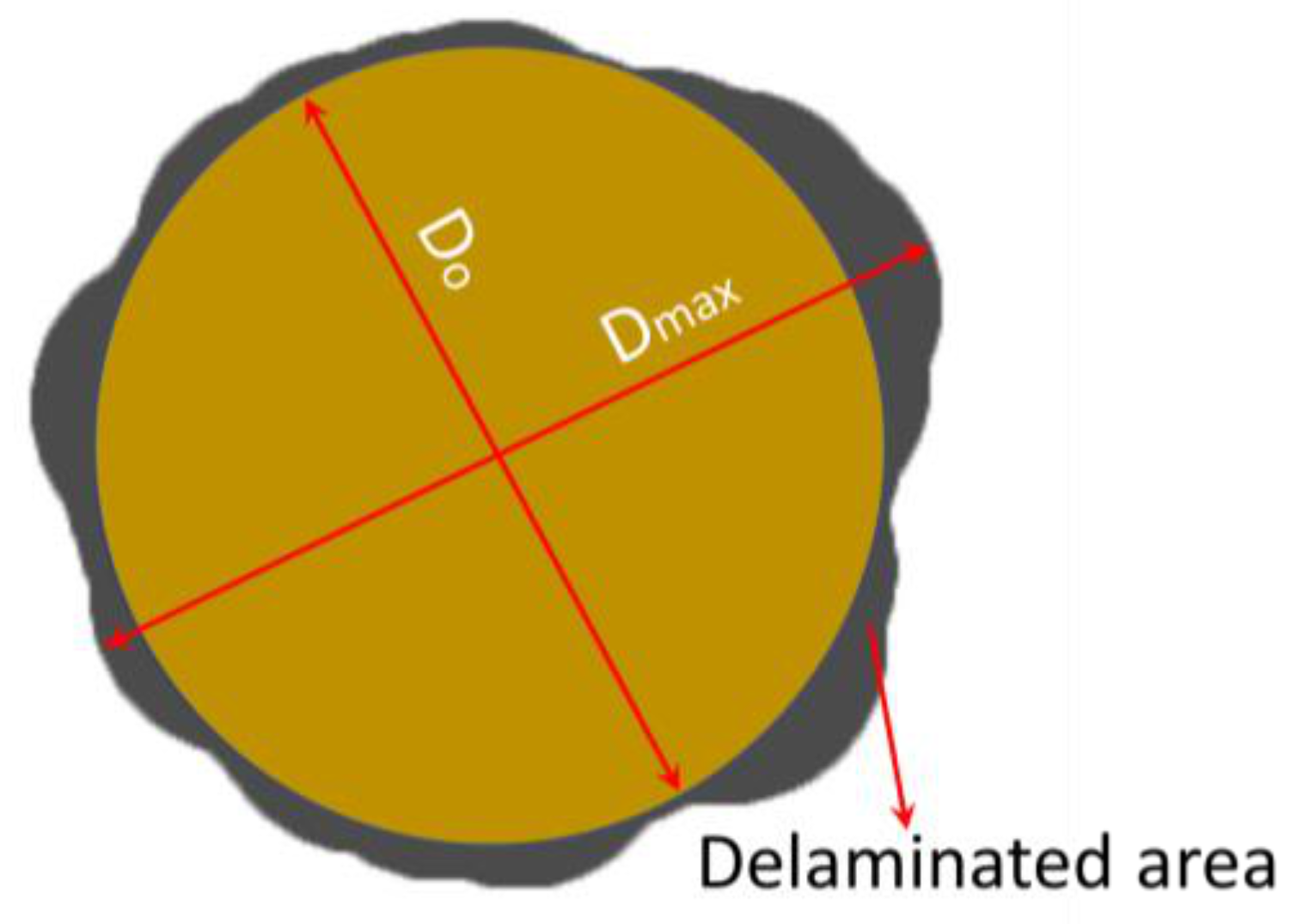
3.2. Delamination Analysis

Table 5 shows the calculated ANOVA results of the delamination factor. The ANOVA results show that the delamination is mostly affected by the point angle. The ANOVA analysis shows the significance of the three parameters in affecting delamination. F-values of point angle, spindle speed, and feed were 383.89, 76.62, and 118.07, respectively, and their corresponding p-values were 0.001, 0.194, and 0. F-value and p-value show that the point angle contributed more to affecting the delamination factor. Thus, the 63.05% contribution of the point angle is the primary factor in deciding the delamination factor, followed by the feed rate of 19.39% and spindle speed of 12.58%.
Figure 5 shows that the increase in the feed rate also increased the delamination, while an increase in the spindle speed also increased the delamination irrespective of point angle. This characteristic is due to the variation in the cutting temperature. In other words, the cutting temperature produced at lower spindle speed is minimum, and the delamination due to this condition formed because of the shearing stress-induced while drilling. At a high feed rate, the composite surface exhibited high stress due to interference from the tool. Therefore, when the tool started penetrating the composite surface, the material surface near the tool edge developed higher stress against penetration. This created high delamination at the entry side of the tool. At a high feed rate, the tool also wore due to the formation of buildup edges [21], which directly corresponded to the increase in delamination. However, at high speeds, the developed buildup edges were removed due to the generation of high temperatures. In addition, at high speeds, the matrix softened due to the increased temperature, which contributed to the rapid cutting of surface and chip removal without any delamination. It can be justified that the lower feed rate and higher spindle speed were suitable for producing holes with reduced delamination. According to the work of Athijayamani et al. [19], the hole quality is the function of matrix and fibre properties. Therefore, delamination can be reduced in the fibre composites by controlling the fibre and matrix ratio, as well as by improving the interfacial bonding.

3.3. Surface Roughness (Ra) Analysis

In the present investigation, surface roughness found on the drilled surface is described by Ra (the average surface roughness). Surface roughness variation with respect to the point angle, spindle speed, and feed rate is shown in Figure 6.
Figure 6 shows that the roughness values were scattered; as such, the surface roughness values did not follow the trend on variation with drilling parameters. This is because of the non-homogeneous property of the composite. The presence of fibre and particles in the composite surface was not uniform. Under drilling, the surface may become more irregular due to the different cut mechanisms involved (Figure 7). The matrix material failed under high stress, while the fragmented matrix was found stuck to the cut surface (Figure 7a). The matrix cracks were noted on the surface due to the high stress developed in the drill face during tool penetration (Figure 7b). Due to high heat generation, the matrix became molten and smeared on the wall of the cut surface (Figure 7c). The high drill force caused the fibres to pull out, protrude from and become deboned from the matrix (Figure 7d). In some regions, the fibres were broken and fragmented, while uncut fibres (Figure 7e) were also noticed at the exit point. These variations in the failure mechanism are the reason for the irregularity and scattering in the surface roughness value. Therefore, it can be concluded that, although it is preferable in metal matrix composites, the surface roughness cannot be considered a factor in defining the drilling hole quality in these types of composite structures. Similar findings were reported by Durão et al. [25].
Table 6 shows ANOVA analysis and the significance of the three parameters in affecting surface roughness. F-value of point angle, spindle speed, and feed were 31.18, 18.69, and 11.59, respectively, and their corresponding p-values were 0, 0.001 and 0.004, which show that the point angle is statistically more significant for surface roughness. Point angle contributed 27.91% in affecting the surface roughness, followed by the spindle speed (16.73%) and feed (10.38%).
Table 7 shows the S/N ratio response table. Delta values in the response table help in identifying the drilling parameters. Based on the delta values, ranks have been given to variables in the order of their significance in the minimisation of thrust force, delamination factor, and surface roughness. In this regard, the minimum thrust force value was obtained at point angle 118°, spindle speed 1000 rpm, and feed rate 100 mm/min (Figure 8). The minimum delamination factor value was obtained at point angle 90°, spindle speed 1000 rpm, and feed rate 100 mm/min (Figure 9). The minimum Ra value was obtained at point angle 135°, spindle speed 1000 rpm, and feed rate 100 mm/min (Figure 10).

4. Conclusions

This study was conducted to analyse the drilling performance of silane-treated sisal/redmud hybrid structural composite on varying point angles, spindle speeds, and feed rates. Thrust force, exit delamination, and surface roughness were investigated using Taguchi analysis. Based on the results, the following conclusions were drawn:
  • The thrust force increased with the increase in the feed rate and spindle speed. Compared to spindle speed, thrust force was highly influenced by feed rate. Drill tool with 118° point angle generated lower thrust force. ANOVA results showed that the spindle speed (39.23%) produced the maximum contribution affecting the thrust, followed by the feed rate (27.51%) and point angle (15.78%).
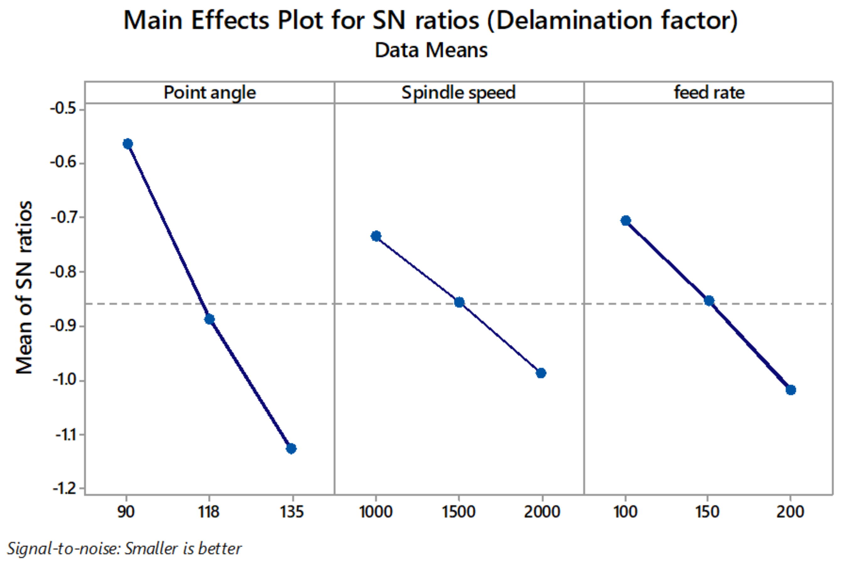
  • Delamination was highly influenced by the feed rate (37.99%). Point angle 90° showed maximum delamination, while minimum delamination was noted at 118°. Variation in spindle showed minor variation in delamination.
  • A quality hole with minimum thrust force was obtained at point angle 118°, spindle speed 1000 rpm, and feed rate 100 mm/min.
  • The minimum delamination factor value was obtained at point angle 90°, spindle speed 1000 rpm, and feed rate 100 mm/min.
  • The minimum surface roughness value was obtained at point angle 135°, spindle speed 1000 rpm, and feed rate 100 mm/min.
According to the findings, redmud-based composites have improved machinability characteristics, which may increase the likelihood of these composites being used in structural applications. This research could pave the way for a better understanding of the machinability behaviour of particle based structural composites.

Author Contributions

Conceptualization, V.S. and U.M.; methodology, V.S., A.V., A.M.B. and M.S.B.A.M.; validation, R.E.N., M.F., G.S., N.R. and O.D.; formal analysis, O.D. and R.E.N.; investigation, A.V. and A.M.B.; data curation, V.S. and S.R.; writing—original draft preparation, V.S. and S.R.; writing—review and editing, V.S., M.S.B.A.M., O.D., N.R., G.S. and M.F.; supervision, O.D. and N.R.; project administration, U.M. All authors have read and agreed to the published version of the manuscript.

Funding

This research received no external funding.

Institutional Review Board Statement

Not applicable.

Informed Consent Statement

Not applicable.

Data Availability Statement

All the data is available within the manuscript.

Conflicts of Interest

The authors declare no conflict of interest.

References

  1. Velmurugan, G.; Babu, K. Statistical analysis of mechanical properties of wood dust filled Jute fiber based hybrid composites under cryogenic atmosphere using Grey-Taguchi method. Mater. Res. Express 2020, 7, 065310. [Google Scholar] [CrossRef]
  2. Sanjeevi, S.; Shanmugam, V.; Kumar, S.; Ganesan, V.; Sas, G.; Johnson, D.; Shanmugam, M.; Ayyanar, A.; Naresh, K.; Neisiany, R.; et al. Effects of water absorption on the mechanical properties of hybrid natural fibre/phenol formaldehyde composites. Sci. Rep. 2021, 11, 1–11. [Google Scholar] [CrossRef]
  3. Das, O.; Loho, T.A.; Capezza, A.J.; Lemrhari, I.; Hedenqvist, M.S. A novel way of adhering PET onto protein (wheat gluten) plastics to impart water resistance. Coatings 2018, 8, 388. [Google Scholar] [CrossRef]
  4. Vigneshwaran, S.; John, K.; Deepak, R.; Uthayakumar, M.; Arumugaprabu, V.; Kumaran, S. Conventional and unconventional machining performance of natural fibre-reinforced polymer composites: A review. J. Reinf. Plast. Compos. 2021, 40, 553–567. [Google Scholar] [CrossRef]
  5. Razavi, S.M.; Neisiany, R.E.; Razavi, M.; Fakhar, A.; Shanmugam, V.; Alagumalai, V.; Försth, M.; Sas, G.; Das, O. Efficient Improvement in Fracture Toughness of Laminated Composite by Interleaving Functionalized Nanofibers. Polymers 2021, 13, 2509. [Google Scholar] [CrossRef]
  6. Shanmugam, V.; Das, O.; Babu, K.; Marimuthu, U.; Veerasimman, A.; Johnson, D.J.; Neisiany, R.E.; Hedenqvist, M.S.; Ramakrishna, S.; Berto, F. Fatigue behaviour of FDM-3D printed polymers, polymeric composites and architected cellular materials. Int. J. Fatigue 2021, 143, 106007. [Google Scholar] [CrossRef]
  7. Shanmugam, V.; Johnson, D.J.; Babu, K.; Rajendran, S.; Veerasimman, A.; Marimuthu, U.; Singh, S.; Das, O.; Neisiany, R.E.; Hedenqvist, M.S.; et al. The mechanical testing and performance analysis of polymer-fibre composites prepared through the additive manufacturing. Polym. Test. 2020, 93, 106925. [Google Scholar] [CrossRef]
  8. Vigneshwaran, S.; Sundarakannan, R.; John, K.M.; Johnson, R.D.J.; Prasath, K.A.; Ajith, S.; Arumugaprabu, V.; Uthayakumar, M. Recent advancement in the natural fiber polymer composites: A comprehensive review. J. Clean. Prod. 2020, 277, 124109. [Google Scholar] [CrossRef]
  9. Vigneshwaran, S.; Uthayakumar, M.; Arumugaprabu, V. Review on machinability of fiber reinforced polymers: A drilling approach. Silicon 2018, 10, 2295–2305. [Google Scholar] [CrossRef]
  10. Rajmohan, T.; Palanikumar, K. Application of the central composite design in optimization of machining parameters in drilling hybrid metal matrix composites. Measurement 2013, 46, 1470–1481. [Google Scholar] [CrossRef]
  11. Jani, S.P.; Kumar, A.S.; Khan, M.A.; Kumar, M.U. Machinablity of hybrid natural fibre composite with and without filler as reinforcement. Mater. Manuf. Process. 2016, 31, 1393–1399. [Google Scholar] [CrossRef]
  12. Basavarajappa, S.; Chandramohan, G.; Davim, J.P. Some studies on drilling of hybrid metal matrix composites based on Taguchi techniques. J. Mater. Process. Technol. 2008, 196, 332–338. [Google Scholar] [CrossRef]
  13. Kumar, S.; Chauhan, S.R.; Rakesh, P.K.; Singh, I.; Davim, J.P. Drilling of glass fibre/vinyl ester composites with fillers. Mater. Manuf. Process. 2012, 27, 314–319. [Google Scholar] [CrossRef]
  14. Rajmohan, T.; Vinayagamoorthy, R.; Mohan, K. Review on effect machining parameters on performance of natural fibre–reinforced composites (NFRCs). J. Thermoplast. Compos. Mater 2019, 32, 1282–1302. [Google Scholar] [CrossRef]
  15. Babu, G.D.; Babu, K.S.; Gowd, B. Optimization of machining parameters in drilling hemp fibre reinforced composites to maximize the tensile strength using design experiments. Ind. J. Eng. Mater. Sci. 2013, 20, 385–390. [Google Scholar]
  16. Chandramohan, D.; Marimuthu, K. Thrust force and torque in drilling the natural fibre reinforced polymer composite materials and evaluation of delamination factor for bone graft substitutes–a work of fiction approach. Int. J. Eng. Sci. Technol. 2010, 2, 6437–6451. [Google Scholar]
  17. Yallew, T.B.; Kumar, P.; Singh, I. A study about hole making in woven jute fabric-reinforced polymer composites. Proc. Inst. Mech. Eng. Part L J. Mater. Des. Appl. 2016, 230, 888–898. [Google Scholar] [CrossRef]
  18. Sridharan, V.; Raja, T.; Muthukrishnan, N. Study of the effect of matrix, fibre treatment and graphene on delamination by drilling jute/epoxy nanohybrid composite. Arab. J. Sci. Eng. 2016, 41, 1883–1894. [Google Scholar] [CrossRef]
  19. Athijayamani, A.; Thiruchitrambalam, M.; Natarajan, U.; Pazhanivel, B. Influence of alkali-treated fibres on the mechanical properties and machinability of roselle and sisal fibre hybrid polyester composite. Polym. Compos. 2010, 31, 723–731. [Google Scholar]
  20. Jayabal, S.; Natarajan, U. Drilling analysis of coir-fibre-reinforced polyester composites. Bull. Mater. Sci. 2011, 34, 1563–1567. [Google Scholar] [CrossRef]
  21. Jayabal, S.; Natarajan, U. Optimization of thrust force, torque, and tool wear in drilling of coir fibre-reinforced composites using Nelder–Mead and genetic algorithm methods. Int. J. Adv. Manuf. Syst. 2010, 51, 371–381. [Google Scholar] [CrossRef]
  22. Durão, L.M.P.; Gonçalves, D.J.; Tavares, J.M.R.; de Albuquerque, V.H.C.; Panzera, T.H.; Silva, L.J.; Vieira, A.A.; Baptista, A.P.M. Drilling delamination outcomes on glass and sisal reinforced plastics. In Mater. Sci. Forum. 2013, 730, 301–306. [Google Scholar] [CrossRef]
  23. Vigneshwaran, S. Machining and Erosion Studies of Red Mud Based Polymer Composites; Kalasalingam Academy of Research and Education: Krishnankoil, India, 2020. [Google Scholar]
  24. Vigneshwaran, S.; Uthayakumar, M.; Arumugaprabu, V. Development and sustainability of industrial waste-based redmud hybrid composites. J. Clean. Prod. 2019, 230, 862–868. [Google Scholar] [CrossRef]
  25. Durão, L.M.P.; Gonçalves, D.J.; Tavares, J.M.R.; de Albuquerque, V.H.C.; Vieira, A.A.; Marques, A.T. Drilling tool geometry evaluation for reinforced composite laminates. Compos. Struct. 2010, 92, 1545–1550. [Google Scholar] [CrossRef]
Figure 1. A typical structural component composite sample during the drilling process.
Materials 14 04468 g001
Figure 2. A schematic diagram of the measurement of the delamination factor.
Materials 14 04468 g002
Figure 3. Drilling cycles for specimens machined with 90° point angle and spindle speed of 2000 rpm with a (a) feed rate 100 mm/min and thrust force 58.56 N, (b) feed rate 150 mm/min and thrust force 78.48 N, and (c) feed rate 200 mm/min and thrust force 107.91 N.
Materials 14 04468 g003
Figure 4. Variation in thrust force on redmud-filled sisal composite structures at different point angles: (a) 90°, (b) 118°, and (c) 135°.
Materials 14 04468 g004
Figure 5. Variation in delamination factor on redmud-filled sisal composite structures at different point angles: (a) 90°, (b) 118°, and (c) 135°.
Materials 14 04468 g005
Figure 6. The variation in surface roughness on redmud-filled sisal composite structures at different point angles: (a) 90°, (b) 118°, and (c) 135°.
Materials 14 04468 g006
Figure 7. The morphology of a drilled hole in the composite structures. (a) Matrix failure, (b) Micro cracks, (c) Matrix smearing, (d) Fibre protrusion, (e) Uncut fibres.
Materials 14 04468 g007
Figure 8. Main effect plot for S/N ratios of thrust force.
Materials 14 04468 g008
Figure 9. Main effect plot for S/N ratios of delamination factor.
Materials 14 04468 g009
Figure 10. Main effect plot for S/N ratios of surface roughness (Ra).
Materials 14 04468 g010
Table 1. Properties of the fabricated composite structure [23].
PropertyUntreated Sisal
Fibre/Redmud Composite
Silane Treated Sisal
Fibre/Redmud Composite
Tensile strength (MPa)4963
Flexural strength (MPa)199244
Impact strength (J/m)2026
Hardness (shore D)7890
Density (g/cm3)1.41.5
Voids (%)3.51.2
Table 2. Process variables and their levels.
SymbolProcess VariablesLevels
IIIIII
APoint angle (°)90118135
BSpindle Speed (rpm)100015002000
CFeed rate (mm/min)100150200
Table 3. Experiment results.
Ex. NoPoint
Angle (°)
Spindle Speed (rpm)Feed Rate (mm/min)Thrust
(N)
S/N Ratio
of Thrust
FdS/N Ratio
of Fd
Ra
(µm)
S/N Ratio
of Ra
190100010029.43−29.381.039−0.3295.332−14.538
290100015049.05−33.811.049−0.4197.521−17.526
390100020068.67−36.741.062−0.5227.900−17.953
490150010049.05−33.811.054−0.4596.538−16.308
590150015058.86−35.401.078−0.6558.078−18.146
690150020078.48−37.901.081−0.6773.961−11.956
790200010058.86−35.401.070−0.5908.646−18.736
890200015078.48−37.901.078−0.6538.191−18.267
9902000200107.91−40.661.092−0.7647.692−17.721
10118100010019.62−25.851.076−0.6345.341−14.553
11118100015029.43−29.381.096−0.79410.048−20.042
12118100020039.24−31.871.122−1.0018.824−18.913
13118150010039.24−31.871.086−0.7216.982−16.880
14118150015049.05−33.811.103−0.8519.124−19.204
15118150020068.67−36.741.122−0.9975.798−15.265
16118200010049.05−33.811.105−0.86812.726−22.094
17118200015068.67−36.741.119−0.97413.286−22.468
18118200020088.29−38.921.141−1.14211.672−21.343
19135100010029.43−29.381.095−0.7852.136−6.590
20135100015039.24−31.871.105−0.8666.630−16.430
21135100020058.86−35.401.157−1.2657.339−17.312
22135150010049.05−33.811.102−0.8474.442−12.952
23135150015078.48−37.901.143−1.1638.313−18.395
241351500200107.91−40.661.164−1.3218.447−18.534
25135200010078.48−37.901.138−1.1226.484−16.237
261352000150127.53−42.111.162−1.3054.958−13.906
271352000200186.39−45.411.185−1.4717.047−16.960
Fd—Delamination factor, Ra—Surface roughness, S/N—Signal to noise ratio.
Table 4. ANOVA results of thrust force analysis.
SourceDFSeq SSContributionAdj SSAdj MSF-Valuep-Value
Point angle25182.515.78%5182.52591.2527.430.00
Spindle speed212,881.439.23%12,881.46440.6968.190.00
Feed rate29031.927.51%9031.94515.9747.810.00
Point angle × Spindle speed42901.38.84%2901.3725.347.680.008
Point angle × Feed rate41040.83.17%1040.8260.192.750.104
Spindle speed × Feed rate41040.83.17%1040.8260.192.750.104
Error8755.62.30%755.694.45--
Total2632,834.3100.00%----
Adj—Adjusted, DF—Degree of Freedom, SS—Sum of squares, MS—Mean square.
Table 5. ANOVA results of delamination factor analysis.
SourceDFSeq SSContributionAdj SSAdj MSF-Valuep-Value
Point angle20.02336863.05%0.0233680.011684383.890.00
Spindle speed20.00466412.58%0.0046640.00233276.620.00
Feed rate20.00718719.39%0.0071870.003594118.070.00
Point angle × pindle speed40.0004511.22%0.0004510.0001133.70.054
Point angle × Feed40.000862.32%0.000860.0002157.060.01
Spindle speed × Feed40.0002910.78%0.0002910.0000732.390.137
Error80.0002430.66%0.0002430.00003--
Total260.037065100.00%----
Adj—Adjusted, DF—Degree of Freedom, SS—Sum of squares, MS—Mean square.
Table 6. ANOVA results of surface roughness analysis.
SourceDFSeq SSContributionAdj SSAdj MSF-Valuep-Value
Point angle246.19127.91%46.19123.095731.180
Spindle speed227.68516.73%27.68513.842418.690.001
Feed rate217.17910.38%17.1798.589311.590.004
Point angle × Spindle speed431.12418.80%31.1247.78110.50.003
Point angle × Feed rate413.368.07%13.363.34014.510.034
Spindle speed × Feed rate424.04814.53%24.0486.01198.120.006
Error85.9263.58%5.9260.7408--
Total26165.513100.00%----
Adj—Adjusted, DF—Degree of Freedom, SS—Sum of squares, MS—Mean square.
Table 7. S/N ratio response table.
LevelThrustDelamination FactorSurface Roughness (Ra)
Point AngleSpindle SpeedFeedPoint AngleSpindle SpeedFeedPoint AngleSpindle SpeedFeed
1−32.66−28.51−29.3532.6920.7122.89−16.79−15.98−15.43
2−30.21−32.76−32.4325.6232.7132.71−18.97−16.4−18.26
3−34.15−35.75−35.2442.5347.4345.25−15.26−18.64−17.33
Delta3.947.245.8916.9126.7222.363.722.652.83
Rank312312132
Publisher’s Note: MDPI stays neutral with regard to jurisdictional claims in published maps and institutional affiliations.

