State-Of-The-Art and Trends in CO2 Laser Cutting of Polymeric Materials—A Review
by
 , , and
Ray Tahir Mushtaq
1 ,
,
Yanen Wang
1,*, 
Mudassar Rehman
1,2 ,
,
Aqib Mashood Khan
3,4 and
and
Mozammel Mia
5,*
1
Department of Industry Engineering, School of Mechanical Engineering, Northwestern Polytechnical University, Xi’an 710072, China
2
Department of Industrial and Manufacturing Engineering, University of Engineering and Technology, Lahore 54890, Pakistan
3
Key Laboratory of High Efficiency and Clean Mechanical Manufacture, Ministry of Education, School of Mechanical Engineering, Shandong University, Jinan 266000, China
4
Department of Mechanical Engineering, Khwaja Fareed University of Engineering and Information Technology (KFUEIT), Rahim Yar Khan 64200, Pakistan
5
Department of Mechanical Engineering, Imperial College London, Exhibition Rd., South Kensington, London SW7 2AZ, UK
*
Authors to whom correspondence should be addressed.
Materials 2020, 13(17), 3839; https://doi.org/10.3390/ma13173839
Submission received: 28 June 2020
/
Revised: 10 August 2020
/
Accepted: 18 August 2020
/
Published: 31 August 2020
Abstract
:Carbon dioxide (CO2) laser cutting finds one of its most relevant applications in the processing of a wide variety of polymeric materials like thermoplastics and thermosetting plastics. Different types of polymeric materials like polypropylene (PP), polymethyl methacrylate (PMMA), low- and high-density polyethylene (LDPE, HDPE), are processed by laser for different household as well as commercial products in the industry. The reason is their easy availability and economical aspect in the market. The problems associated with laser cutting include heat-affected zone (HAZ) generated on the cut surface, kerf width (KW), surface roughness (SR), dross formation, and striations formation. Furthermore, other related problems include taper cutting for deep parts and high-power consumption. The primary purpose of this work is a comprehensive literature review in CO2 laser cutting of polymeric materials. The influence of parametric variation on the cut quality is also explained. Cut quality in terms of KW, SR, HAZ, dross formation, and striations formation is analyzed by optimizing cutting variables like laser power (PL), cutting speed (CS), assist gas pressure (Pg), pulse frequency, nozzle type and its diameter, and stand-off distance (SOD). The effects of the laser cutting on the properties of different thermoplastics/thermosetting materials are also reported. However, this topic requires further studies on exploring the range of polymeric materials, and their optimal parameters selection to improve the cut quality. Therefore, the research gaps and future research directions are also highlighted in the context of CO2 laser cutting for polymeric materials.
1. Introduction
Conventional machining processes are able to process a large variety of materials. However, the complex profiles are difficult to be generated by these processes [1,2,3]. These processes also possess some restrictions to treat with difficult to machine materials. The nonconventional machining processes like electric discharge machining (EDM), electron beam machining, electrochemical machining, and abrasive water jet machining are also employed to achieve fine and accurate machining of materials. These processes can also generate complex profiles in difficult to machine materials.
An advanced technology named as laser beam machining is becoming the backbone of the materials processing industry due to its numerous applications and processes. Laser (an acronym for light amplification by stimulated emission of radiation) cutting can be performed by melting or vaporization of the material by melt shearing or by vaporization cutting. Laser cutting offers a highly precise cut quality by optimizing laser parameters to produce a little surface roughness (SR), and minimum heat-affected zone (HAZ). Laser cutting is also independent of material hardness. It offers more material utilization, no tool wear, and high cut quality [4,5,6,7]. Caiazzo et al. [8] presented an experimental study of process variables in carbon dioxide (CO2) laser cutting of polymeric materials such as polycarbonate (PC), polypropylene (PP), and polyethylene (PE). The effect of CO2 laser cutting of different polymer materials at different settings of laser parameters was analyzed and explained. It was proved that cut quality could be enhanced by using a low power CO2 laser.
A significant work is already available on the laser cutting of metals, composites, and alloys. Although, a significant breakthrough is also made in the laser cutting of polymeric materials over the last few decades. However, the laser cutting of polymeric materials is still needed to be explored further to enhance cutting efficiency. Therefore, this work is done to study the laser cutting of polymeric materials for a variety of household, and industrial applications. Numerous research studies on laser cutting have been reported to reduce HAZ, SR, dross and striations formation, and enhance material removal rate (MRR). The purpose of this work is a comprehensive literature review on cutting plastic polymers using a CO2 laser to understand and investigate the cut quality in terms of HAZ, kerf formation, SR, dross formation, striations formation, and material removal rate (MRR). Emerging challenges and future trends have also been proposed in the end.
2. Classification of Polymers
In general, macro-molecular compounds properties are strongly linked to changes in temperature [9]. Amorphous polymers at sufficiently low temperature are harder and glass-like, while at normal critical temperature they take a softer and moldable form, the glass transition temperature () [10]. At higher temperature , polymer chain shows an increased variability that allows the flow of the bulk material. Flexibility is restricted at temperatures below , and the polymer turns into a glassy, flexible, or elastic solid. is conditioned by its structural chemistry, physical or chemical interconnection, and molecular weight [11]. The value is considered as an important indicator of either a thermosetting or thermoplastic polymer’s classification of the plastic compound.
Synthetic polymers (like PP, PE) and semisynthetic polymers (like vulcanized rubber) have inherent material properties influenced by the values of the parameter that vary by molecular weight, as defined by Fox and Flory [12] with the relation reported in Equation (1).
Here, is the maximum temperature at which the qualitative infinite molecular mass can be attained, K is an analytical value linked with the free polymer sample volume, and Mn is its mean molecular weight [12].
2.1. Thermoplastic Polymers
Thermoplastic polymers like PE, PC, and PP, are the polymeric materials that, become softer and then harder after heating and cooling. When heating thermoplastic polymers to their melting point, they melt into a liquid. When these polymers are cooled below the , they freeze to a glassy state. Thermoplastic polymers become soft and go into a viscous liquid state after reaching the or melting temperature. These polymers are then converted into glassy or semi-crystalline solids following the cooling method [13]. This process allows small cooling and heating cycles without any structure or function repercussions. For instance, shape and color altering, microstructural changes, and mechanical failure produce a reversible and restricted thermoplastic melting solidification behavior [14,15]. The whole crystal structure is changed if the heating temperature of the thermoplastic polymer is higher compared to its melting point. The linear molecular link chain dispersed randomly and changed special physico-chemical composition [16].
2.2. Thermosetting Polymers
Thermosetting polymers, also designated as thermosets, are irreversible plastic materials. The permanent changes can be made by heating over 200 °C. When a thermoset polymer heats up more than its melting point, the liquid–solid-state transition becomes irreversible, and it is called the solidification process. In the curing procedure, small molecules form a chemical bond, build complicated networks, and then establish a permanence of hard and rigid substance [13]. Similar to thermoplastics, the thermoset plastics are not temperature-dependent on the mechanical characteristics like tensile strength, hardness, and compressive strength.
3. Laser Cutting Mechanisms
The mechanism for the determination of a combination of material, assist gas, and laser type can be divided into three different categories which include vaporization cutting, fusion cutting, and chemical degradation.
3.1. Fusion Cutting
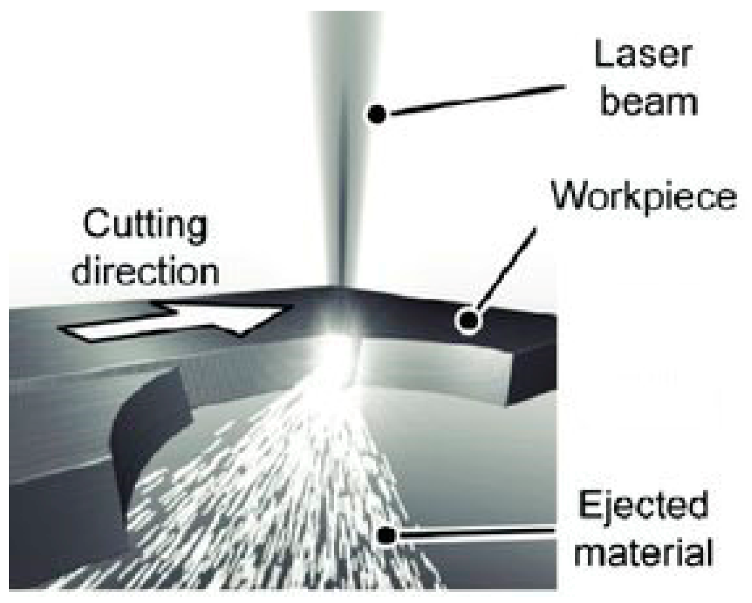
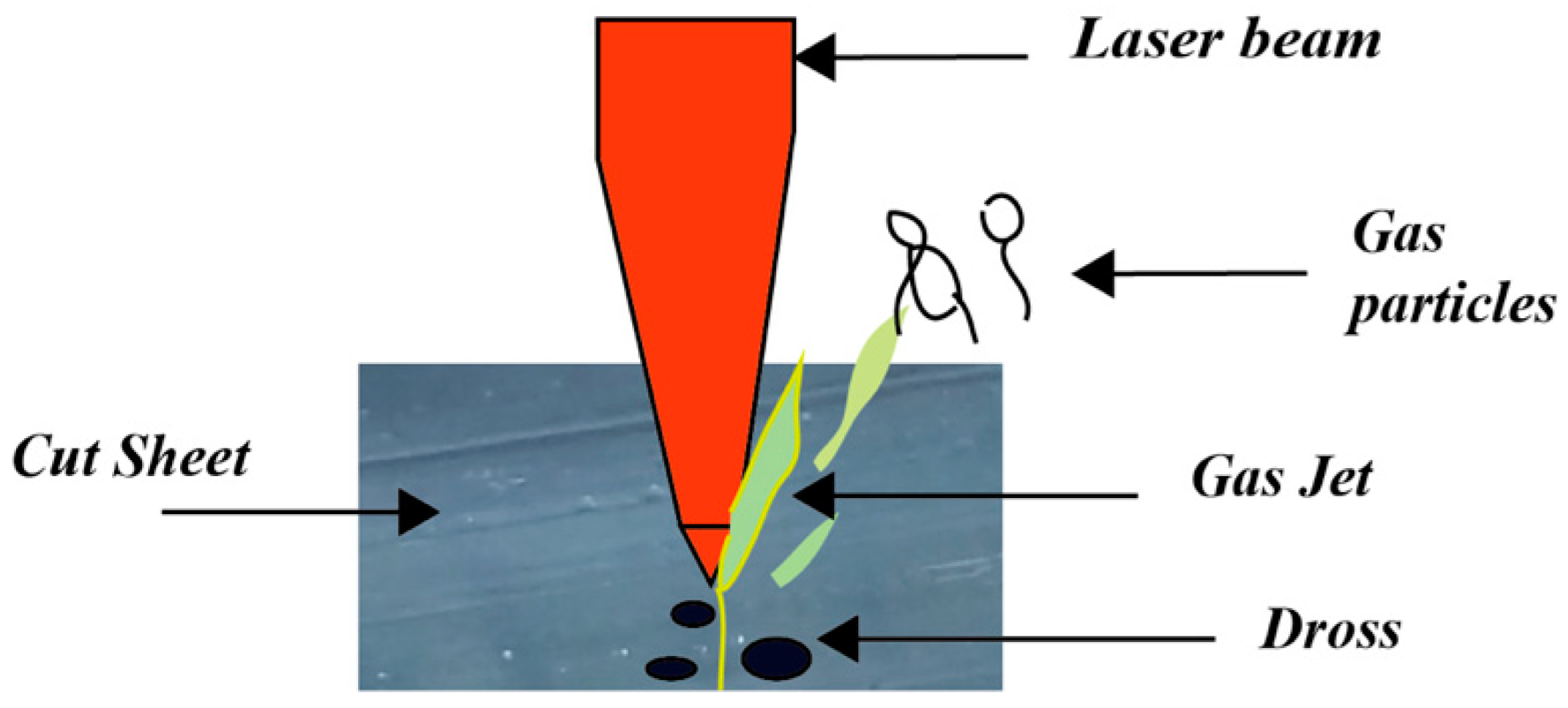
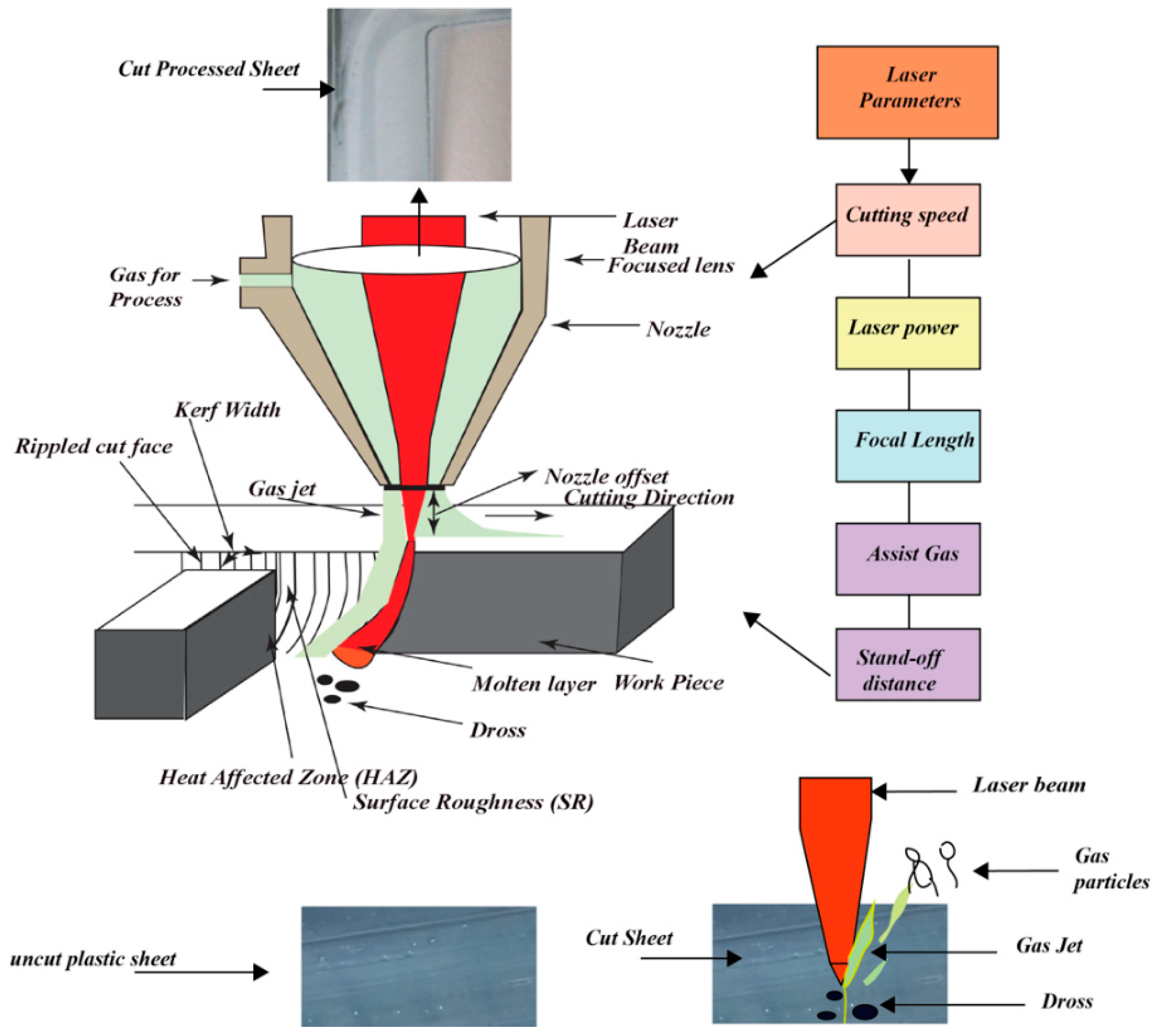
Most thermoplastics are cut by melting the material, and this process is known as fusion cutting [17,18,19,20]. The underlying mechanism is similar to the inert gas metal cutting because it melts the material in-depth. The assist gas (usually compressed air) takes away the molten material, which is used to cut the workpiece. The kerf width (KW) varies between 0.2 mm and 0.8 mm depending on the material thickness. The cutting edge and the face are macroscopically smooth with certain streaks that are formed by the melt material from the laser beam from the point of entry to exit point. The materials that can be cut by fusion contain PE, PC, and PP [8]. The laser creates a small molten pool which is constantly blown away by the assist gas as can be seen in Figure 1 [21]. The cutting parameter level values for different polymeric materials are reported in Table 1.
3.2. Vaporization Cutting
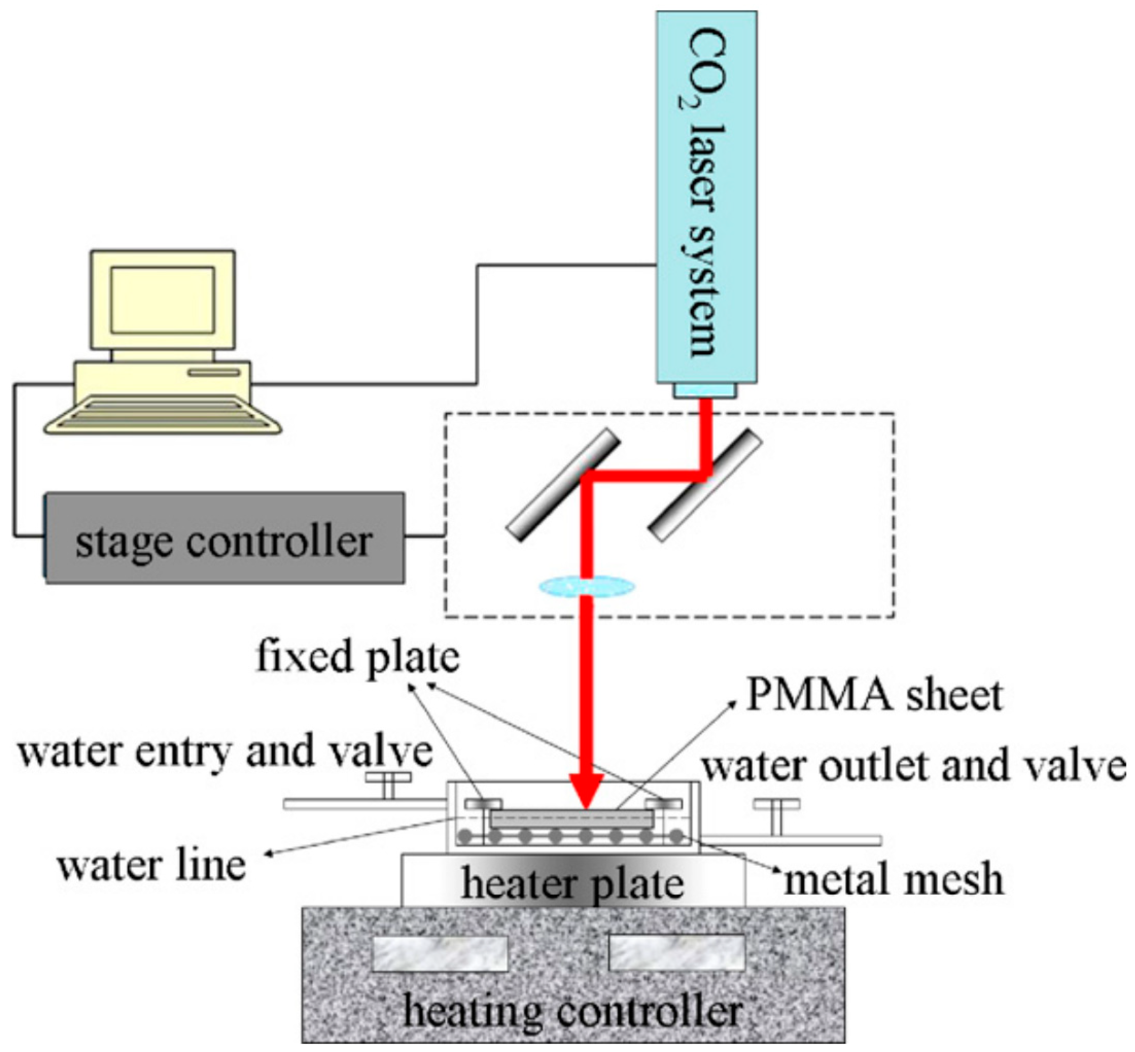
In this type of cutting, the material is quickly heated to the temperature before significant thermal conduction melting occurs. Then, vaporization takes the material away and the fluid is normally ejected through the inert gas jet with the laser beam. The plastics mostly cut through the vaporizing mechanism include polymethyl methacrylate (PMMA), and polyacetal. An illustration of CO2 laser vaporization cutting is shown in Figure 2 [23]. The cutting edge resulted in high quality and produced a little kerf. This form is applied to thin portions since a unit quantity of material needs more energy to be removed [22,24]. The cutting parameters level values for PMMA material are reported in Table 2.
3.3. Chemical Degradation
The laser beam changes the material integrity by breaking chemical bonds in this mechanism, such as woodcutting. Woodcutting reduces big cellulose molecules to the main components of carbon as well as water vapor. The chemical degradation mechanism is used to cut a variety of thermosetting polymers such as rubber and epoxy resins. The mechanism generates a smooth and flat cut edge. The edge quality of cutting materials in chemical degradation is higher compared to the mechanical actions (conventional cutting) because it is soft and free of scattering. However, the cutting edge in this mechanism is covered with residual carbon layer dust that may require cleaning [22,24]. The cutting parameters levels for different thermosetting polymers are given in Table 3.
4. Quality Characteristics of Laser Cutting Edge
The accuracy in laser cutting is highly dependent on its quality characteristics such as KW, SR, dross, charring, and width of HAZ. The quality characteristics of the laser cutting are highly dependent on the input parameters, and their levels. The following section discusses these key features to address the cut quality (also known as quality characteristics).
4.1. Kerf Formation
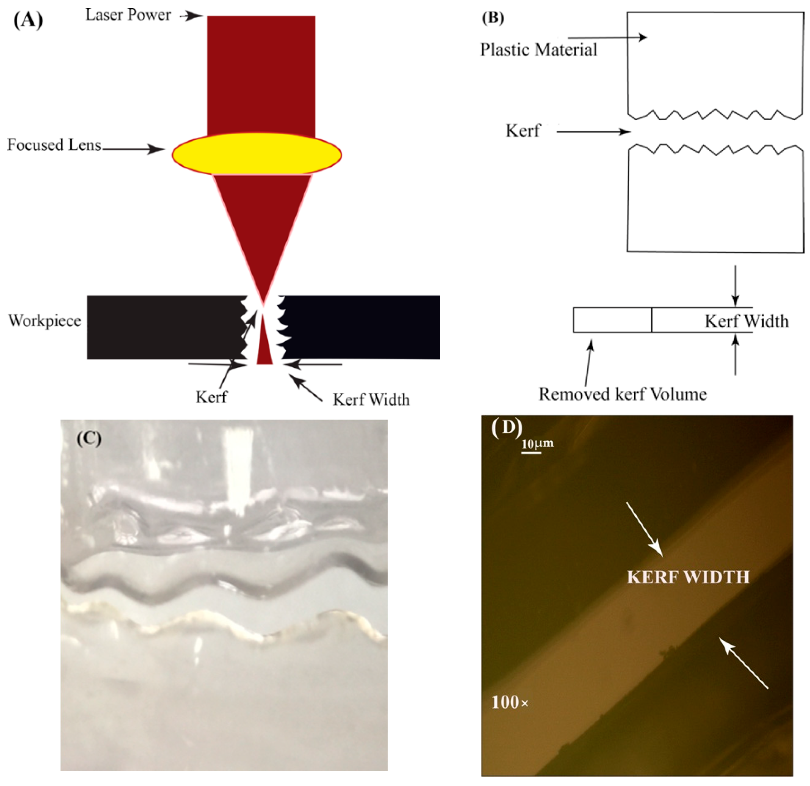
Kerf is defined as the slot produced as a result of material erosion and KW is the measurement of the excessive material removed (width of the cut slot) [25]. Thus, the slot produced by the laser is called kerf, and the width of that slot is called KW. The illustration of KW is shown in Figure 3. Eltawahni et al. [26] studied the kerf properties for PMMA and classified them as upper, middle, and lower kerf. Yilbas et al. [27] suggested a scaling law method to analyze the parametric trends for KW. It was concluded that both PL and KW are directly proportional to each other, while CS is inversely proportional to KW by keeping PL constant. KW is increased by increasing the workpart thickness. The focal point position of the lens caused an increment or decrement in the KW of material. Mathematical modeling is used to find an optimized value of KW and the model revealed the correlation with the measured KW of the PMMA material at low PL [28]. Sulaiman et al. [29] explained the influence of different process variables like PL and CS on KW in laser cutting. It was inferred that PL and CS are highly significant for KW, and high-power lead to a wider kerf formation. Hossain et al. [30] explored the behavior of different process variables on kerf formation and resulted that stand-off distance (SOD), CS, Pg, and PL are highly influential parameters for KW. Gross et al. [31] reported the difficulties in understanding of a melting flow layer such as high temperature, intensity, Pg, and dense structure of the kerf. An enhancement in PL increased the KW, whereas an increase in CS reduced the KW [32,33].
The physical model of the material and kerf are shown in Figure 3A. Pictorial representation of kerf and removed material is shown in Figure 3B. Figure 3C indicates the physical view of the kerf. The microscopic examination of KW for the PE sample at 100× magnification is shown in Figure 3D.
Tamrin et al. [34] examined the influence of PL and CS on performance measures such as MRR, and KW for PC. As a result, CS varied inversely with the work part thickness, and directly with the MRR. The authors also inferred that upper KW was found 1.5 times larger as compared to bottom KW. They further noted that the cut quality varied directly with the PL up to a certain threshold extent and then gradually reduced.
4.2. Striations Formation and Surface Roughness (SR)
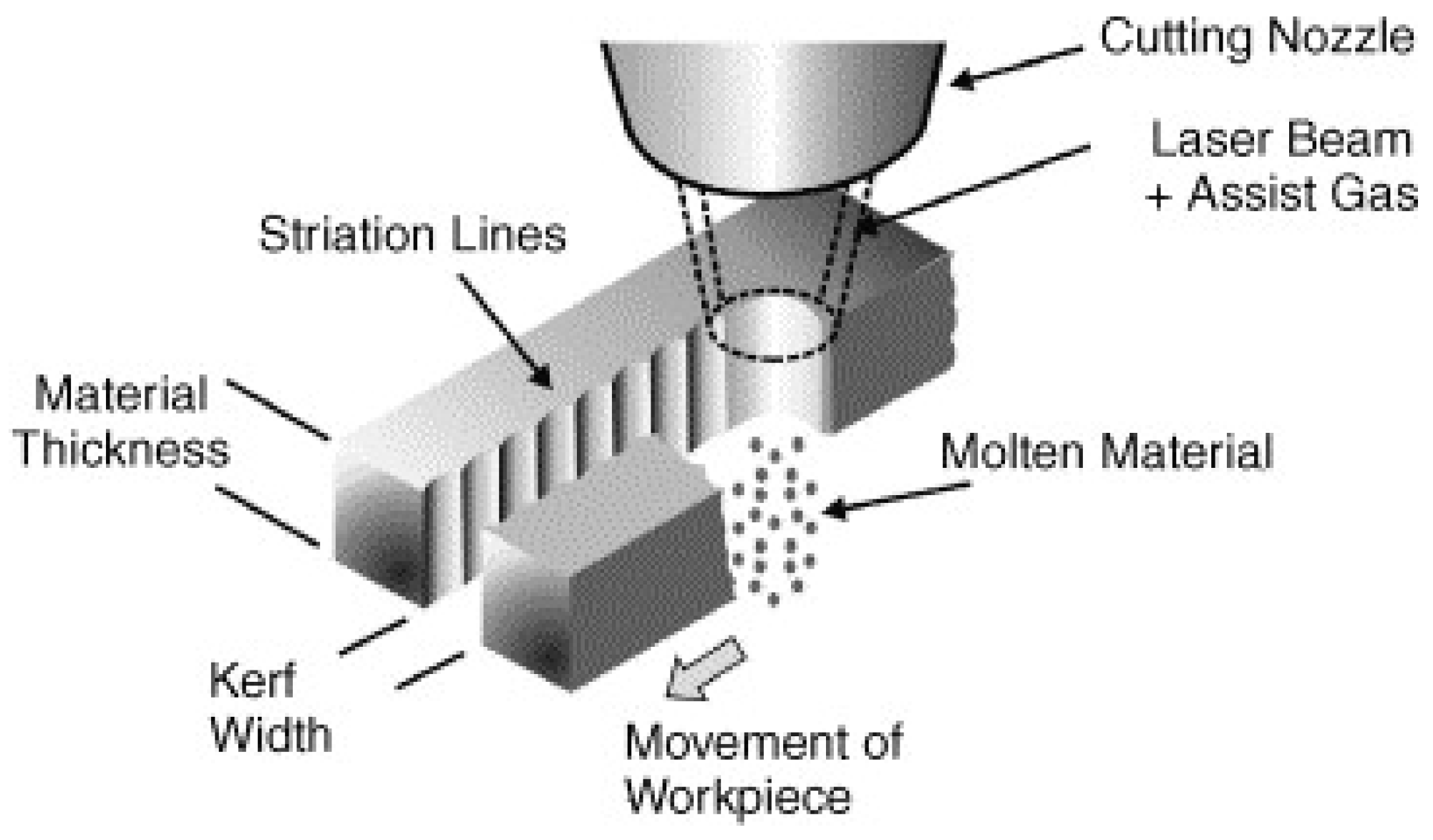
Striation formation is another quality characteristic of laser cutting surface. The surfaces that are cut with a laser beam are usually striated almost constantly resulting in a rough surface. Striations are not just produced by vibrations of the machinery. They appear in all the cases, independently of the laser workpiece displacement system vibrations. A schematic representation of striations formation is indicated in Figure 4.
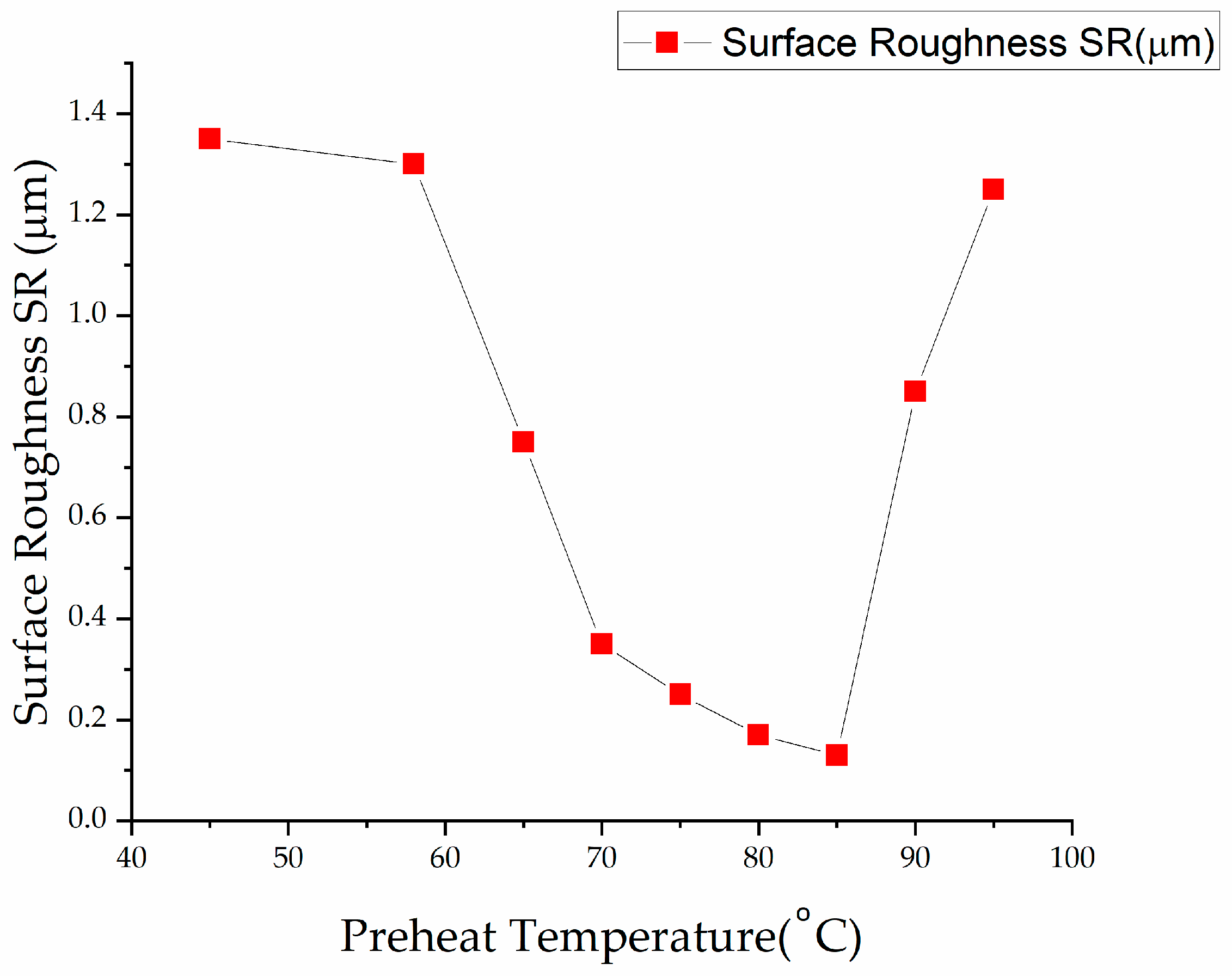
The striation must be reduced to achieve optimized laser cutting, resulting in minimal SR [36]. The preheated temperature is needed to give a fine cut, and decreased SR in the case of PMMA plastic as can be seen in Figure 5 [23]. Yilbas et al. [37] conducted a comprehensive study to analyze striation formation and its influence on laser cutting variables. They inferred that the major reasons for striations formation include side-by-side burning, variation in absorbed power caused by surface plasma, and fluid layer surface oscillation.
4.3. Dross Formation
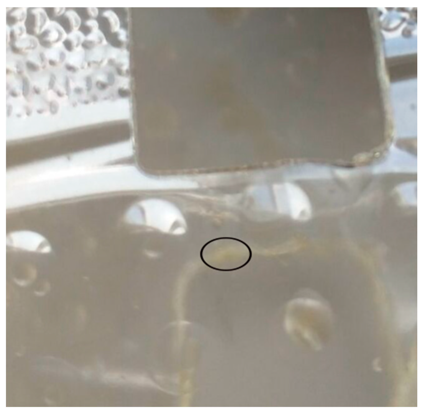
The material stuck to the bottom of the work part after the laser cutting is called dross formation as demonstrated clearly in Figure 6. The dross may be solidified if the inert gas acts as an assist gas. Dross formation is dependent on the viscosity, and surface tension of the molten material. Materials with high viscosity and more surface tension resulted in more dross formation.
Gas jet is used to eliminate dross from the underside of the part and mechanically removed after cutting [22,24,36]. Schuöcker et al. [38] conducted an experimental study on dross formation at the material edges as a result of laser cutting. As a result, dross and slag formation occur at the kerf wall not in the middle.
4.4. Heat-Affected Zone
The HAZ is created during the laser cutting due to more localized heat and is the closed cutting zone (see Figure 7). Width size of HAZ is enhanced with the increase in energy input and cutting thickness for each unit length. The size of the width of HAZ is important to make cuts close to heat-sensitive sections. Besides this, it is not usually included in the laser cut quality evaluation [22]. Abrão et al. [39] reported the influence of different input variables to create a fine and effective cut in laser cutting. A proper experimental design was established to investigate the parametric effects. The burning of the workpiece occurs when the laser tool speed is less compared to its critical speed [40]. The thermal effects induced on the workpiece surface were reported by Ohkubo et al. [41] as examined by scanning electron microscopy.
4.5. Charring
Charring is defined as the chemical process caused by incomplete combustion during laser cutting. It is recognized by a black line in carbon-based materials. Therefore, the PL should be controlled to avoid burning. Caiazzo et al. [8] examined the influence of laser cutting variables on charring formation. It was resulted that charring is reduced by increasing CS and decreasing PL. Akitt et al. [42] proposed an electronic supervisory system to improve power stability, and accuracy in laser processing. The PL was measured after each quadrant of laser output for the calculation of its stability.
5. CO2 Laser Parameters for Polymeric Materials Processing
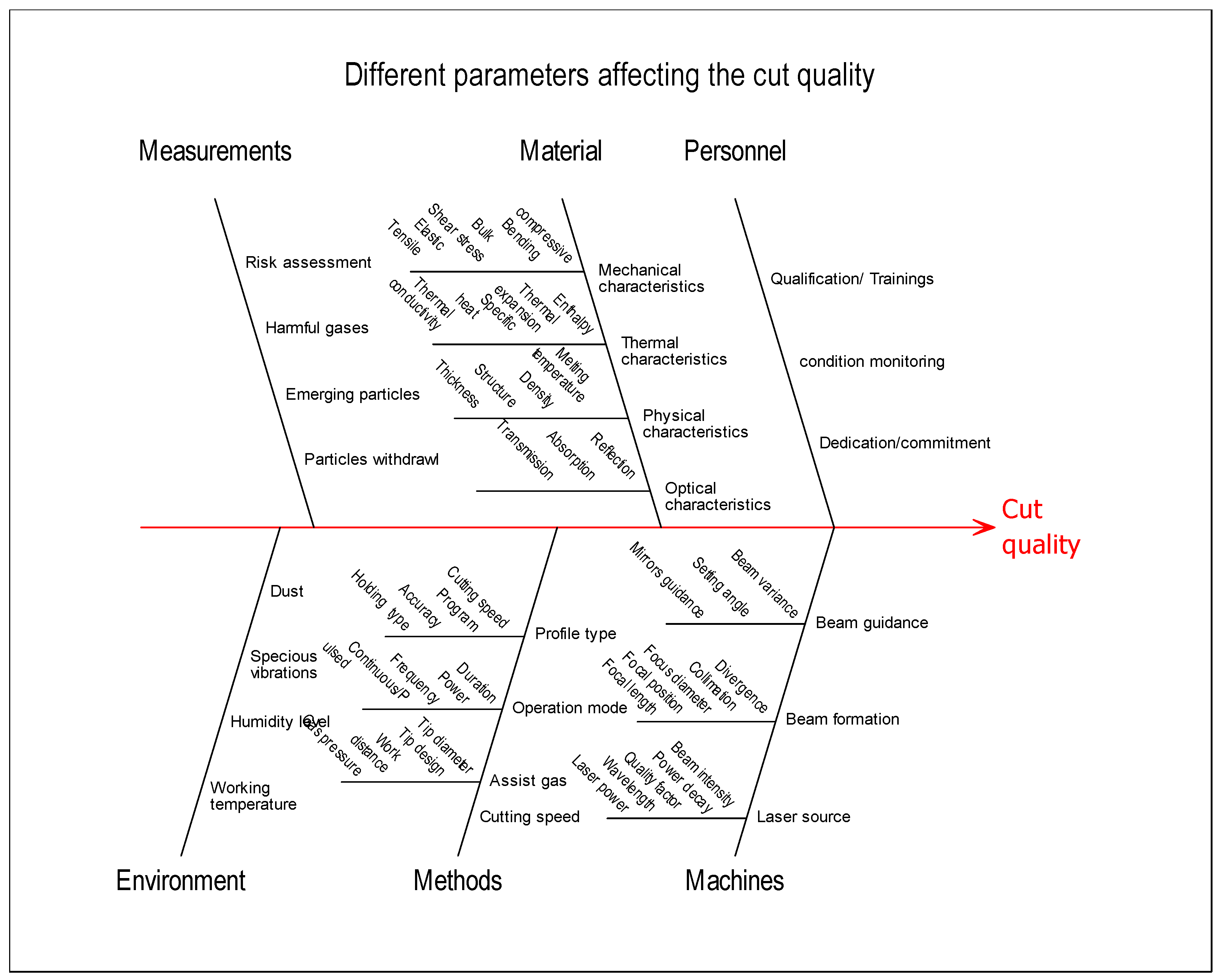
The characteristics of the work material, laser beam, the required KW, precision needed for the cutting process, and workpiece width are the main attributes on which laser cutting variables depend upon [43]. There are other various characteristics that directly or indirectly influence on the cut quality. A detailed illustration of different parameters affecting the cut quality is described in a cause and effect diagram as elaborated in Figure 8 [44].
Kuo et al. [45] reported the comparison of low- and high-power laser in laser cutting. It was inferred that cut quality is significantly influenced by varying CS and PL compared to other process input parameters. Figure 9 highlights some of the essential laser cutting variables.
5.1. Laser Cutting Speed
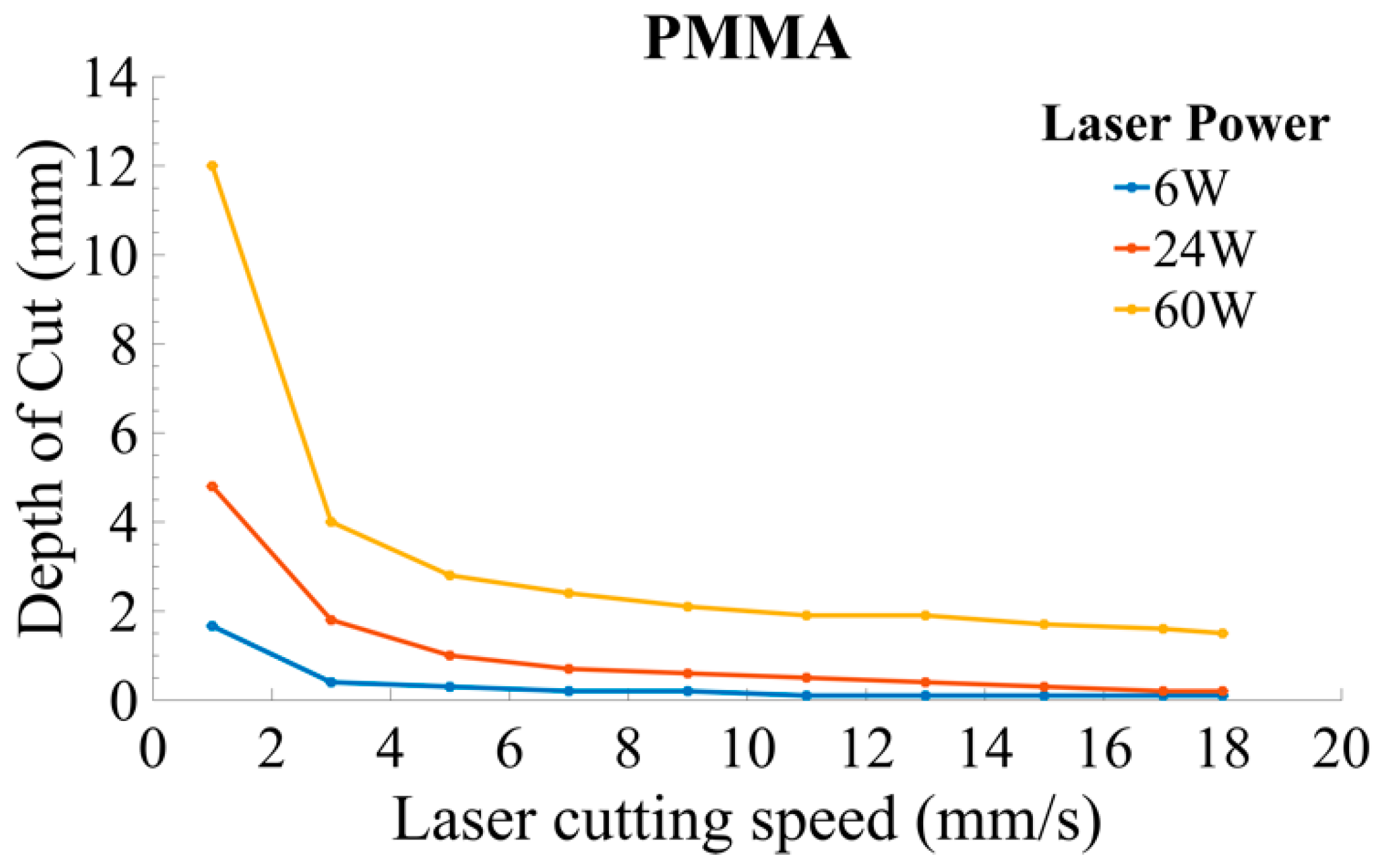
The thermally affected region is reduced as a result of the increased CS. Therefore, CS should be kept high to minimize the thermal damages in the workpiece. The cut quality is highly influenced by CS. Depth of cut (DOC) varies inversely by increasing CS. Zhou et al. [46] derived the relationship of CS with DOC and PL for PMMA material
where CS symbolizes the cutting speed, PL is the laser power, and α denotes the energy absorptivity. It is presumed that the laser radiation is entirely absorbed by material where α = 1. Q is the specific heat of the material, Rb = 0.25 mm describes the radius of the laser beam, ⍴ denotes the material density, and DOC depicts the depth of cut. B and ω are constants with the properties of the material. The values of B and ω have been checked from experiments. For different materials, B and ω have different values. Materials constant values used in Equation (2) are mentioned in Table 4. The expression reported in Equation (2) indicates that CS is varied directly as PL, and inversely with the cutting depth as depicted in Figure 10. The equation can be applied for practical reasons by the industries. They can use it to cut more depth material at low CS and low PL or adjust according to the requirement.
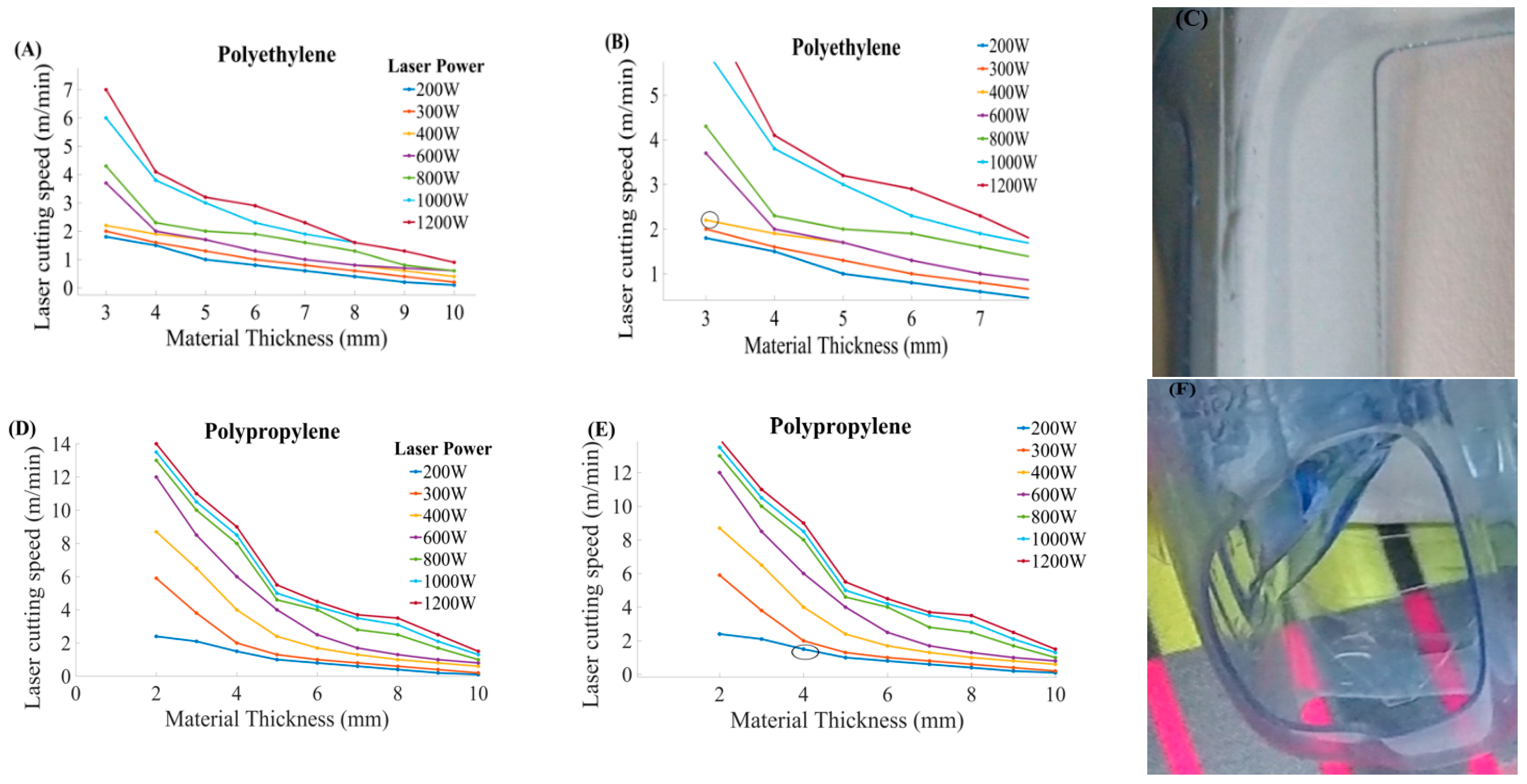
PE and PP material were cut at a different material thickness. It was observed that the thick workpiece needed high CS while the thin material needed less speed, as illustrated in Figure 11. Controlled CS is required to cut different thickness that leads to obtaining good cut quality.
Parametric trends for CS and thickness for PE at different power ratings as depicted in Figure 11A. It can be seen that CS is inversely proportional to the work part thickness. Figure 11B indicated the pointed part of Figure 11A. The CS for PE material was set at 3.8 mm/s, PL of 300 W, along with the cutting thickness of 2 mm. The cut part is presented in Figure 11C. Figure 11D describes the parametric trends of CS and thickness for PP at various powers. Figure 11E indicated the pointed part of Figure 11D. The PP material with a 6 mm thickness was cut at 1.5 mm/s and 200 W PL. Figure 11F illustrates the pictorial view of the machined part.
- Vishnulal et al. [47] performed an experimental investigation of CS, PL, and vibrational frequency (workpiece vibrations) for improving the laser cut quality in terms of MRR for PMMA, PC, and PP. The authors concluded that low-frequency vibrations ranging from 12 to 24 hertz (Hz) improved the cutting rate with more microcracks on the cut surface. Hashemzadeh et al. [48] found that CS is increased by increasing workpiece vibrations: a 12-Hz vibration frequency raises the CS from 0.2 m/min to 0.4 m/min. The proposed the two-pass fabrication method to increase MRR. It was concluded that various issues related to cutting like optimal parameters selection, dimensional variations, energy input, and HAZ width can be controlled by the careful optimization of CS, Pg, and PL using the two-pass fabrication method.
- Nozzle diameter and CS are considered as the main factors for energy utilization effectiveness. An optimal parameter setting is required to utilize energy effectively [49]. The high temperature generated during cutting resulted in low cut quality because of the more HAZ produced. PL and CS found significant variables to control the thermal effects of the work material [50]. Pietro et al. [51] analyzed the influence of CS on steady-state front temperature. The authors realized that both CS, and temperature are directly proportional to each other. It was further added that CS is increased because of heating edges during cutting.
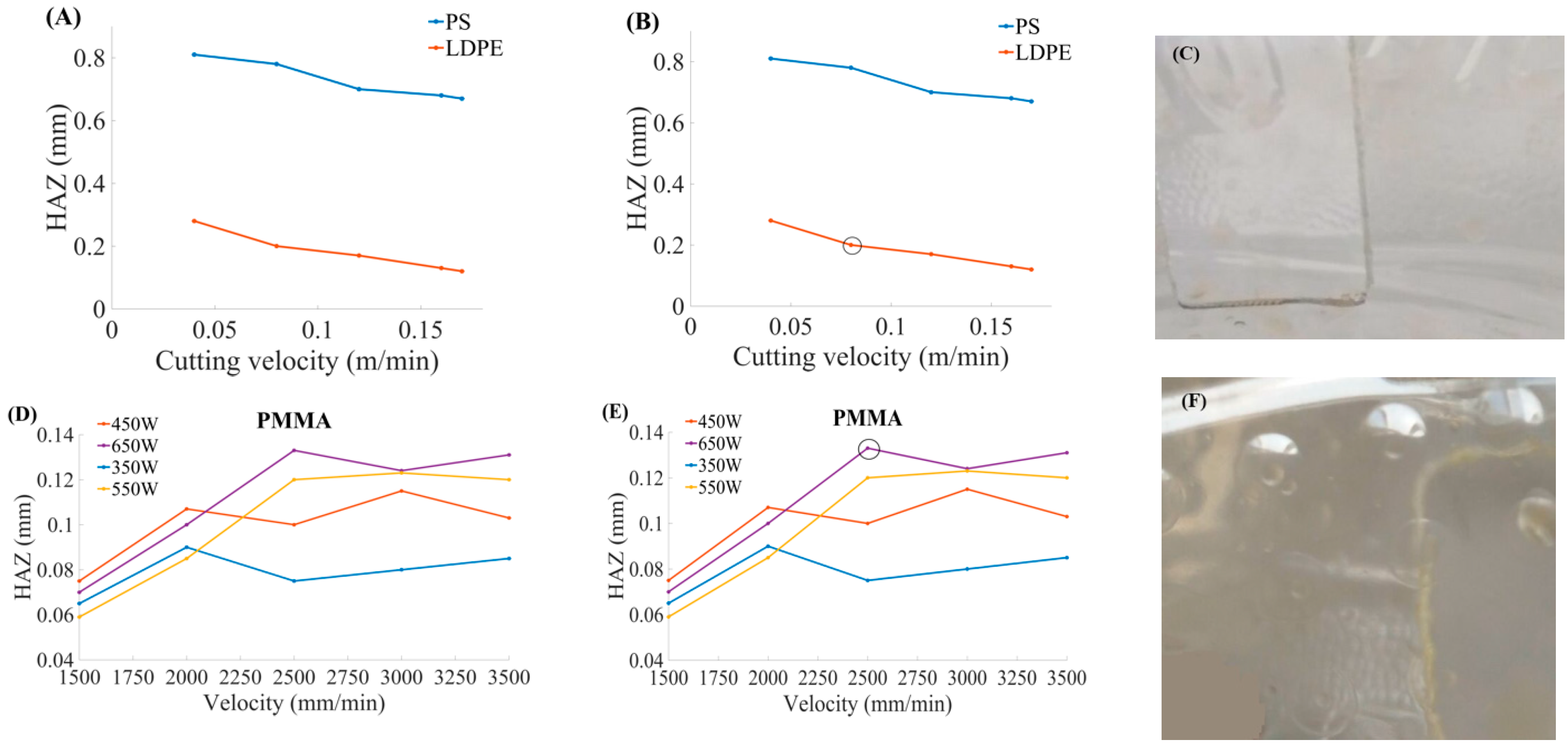
The HAZ is decreased by increasing CS but sometimes shows fluctuating behavior. There should be a controlled CS to minimize HAZ, and SR. The relationship of HAZ, and CS for PS, low-density polyethylene (LDPE) material [52], and PMMA material where it shows fluctuating behavior [53] as illustrated in Figure 12.
The HAZ was analyzed showing behavior for PS, and LDPE with respect to CS, as shown in the pointed part of the graph Figure 12B. Parametric trends indicated the relationship of CS, and HAZ for the PMMA material at different PL values as illustrated in Figure 12D. The CS was found directly proportional to PL. The CS is increased with the increase of the PL. This material (PMMA) showed fluctuating behavior of the HAZ by varying CS, and PL. The machined specimen is shown in Figure 12F in a pointed zoom graphical representation from Figure 12E.
5.2. Laser Power
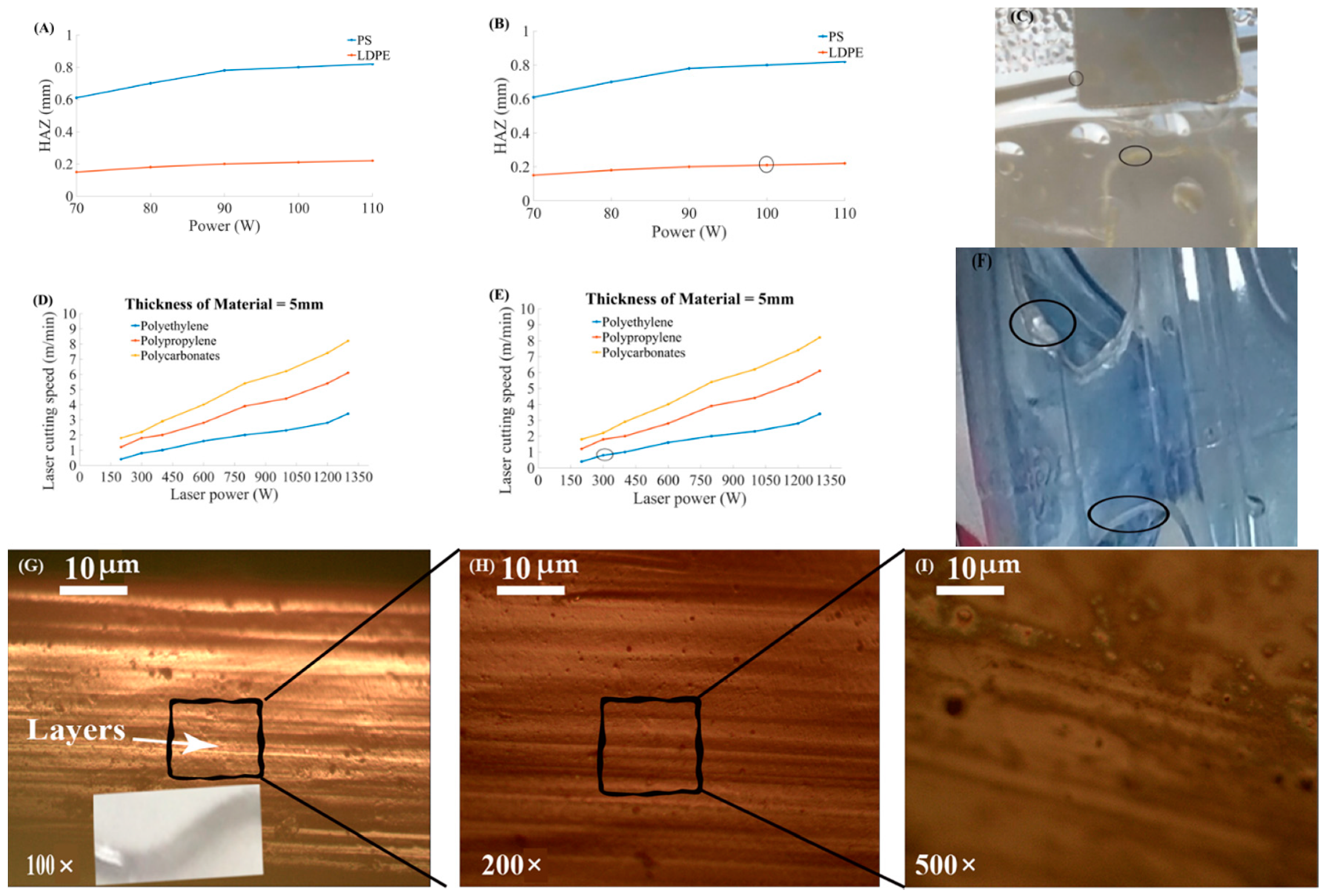
The examination of thermal efficiencies has proved that low power leads to obtain a good cut quality. Usually, high PL is employed for fast melting and ejection of work material during cutting. Stepak et al. [54] performed CO2 laser cutting of polylactic acid (PLLA) material for making tubular stents in surgical applications. Cut quality and geometry were studied by the changes in PL and CS during machining. Sahin et al. [55] found that thermal efficiency is decreased by increasing PL. It was also found that the combination of high CS and less PL lead to better thermal efficiency. Sahin et al. [56] explained the requirement of high thermal efficiency in the context of PL. Madić et al. [57] described the importance of optimal PL in laser cutting. It was inferred that Taguchi and response surface methodology (RSM) are the vital tools to obtain the optimal results. Karimzad et al. [52] studied the influence of PL and CS on cut quality in laser cutting of two different polymeric materials like LDPE, and PS. It was concluded that the combination of low PL and high CS reduced the area of HAZ. It was also proved that the SR and tensile strength of the material are directly proportional to each other. The parametric trends for PL and other different parameters are presented in Figure 13.
The relationship between PL and HAZ for different polymers is described in Figure 13A. The HAZ is increased by increasing PL [24]. According to this reported Figure, all materials indicated an increasing trend with HAZ, and CS by varying PL. LDPE exposed a significant variation in the HAZ. The response of the material is illustrated in Figure 13C. The zoomed graphical curve of the LDPE material is shown in Figure 13B. The material that showed a small HAZ at low PL is evident in Figure 13C. Figure 13D indicated the parametric behavior of PL and CS for different polymers. In Figure 13F, the 5 mm thick material was cut to examine the relationship between PL and the CS. The zoomed part is shown in Figure 13E. The zoomed microscopic image of the cut edge is indicated to examine the cutting quality and the effect of the power on the plastic and resulted in a slight change of voltage creating layers on the cutting edge. In Figure 13G–I, scanning electron microscopy at 100× magnification indicated the layers on edge. It revealed the spots formation because of the dense focal spot heated thick focal spot. Such spots can also be formed when the ejected material touches the edge while cutting is ongoing. It needed optimal CS, and PL to minimize the layers, and spots on edge to get finer cut.
5.3. Lens Focal Length
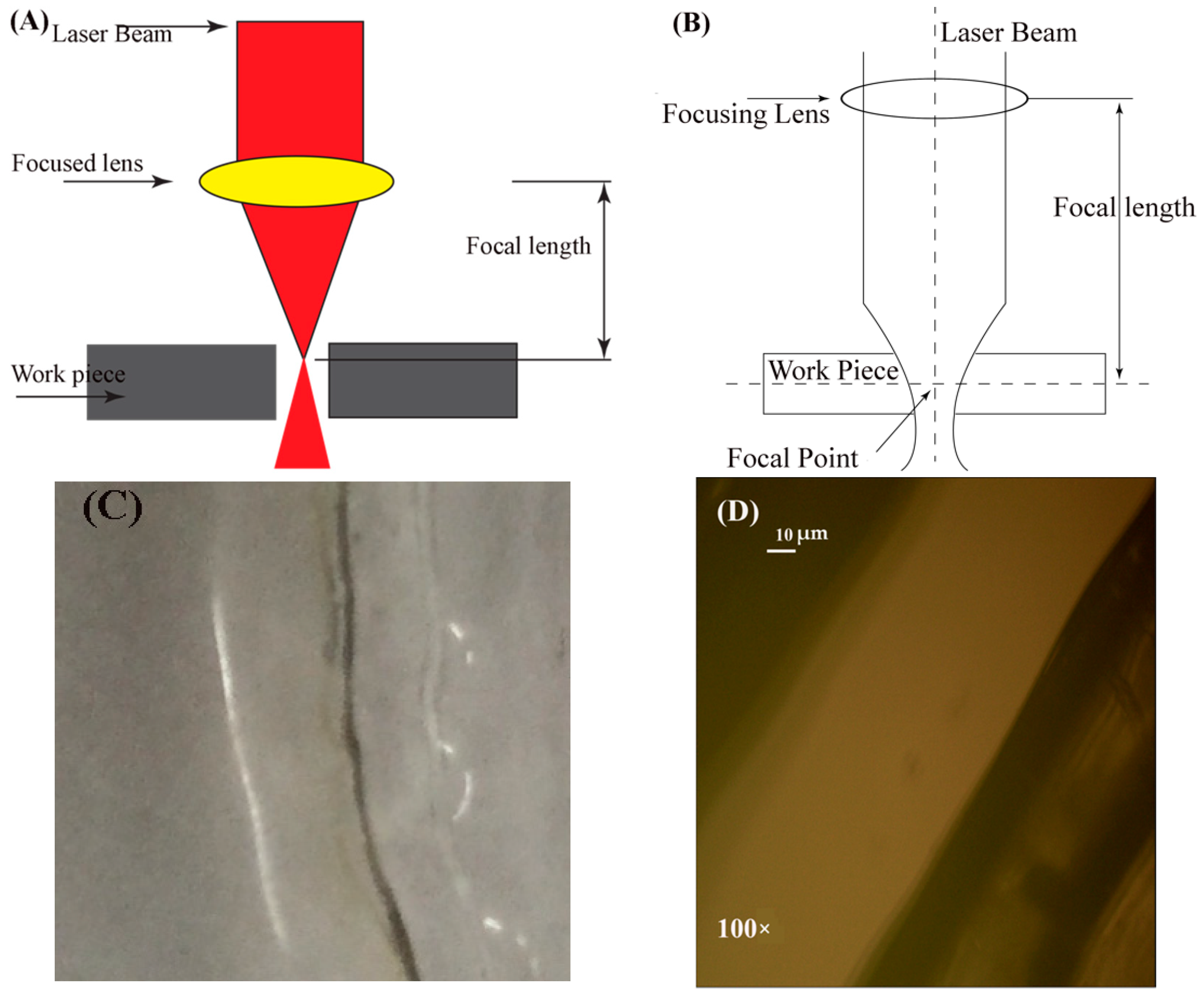
The primary purpose of a lens is to converge and focus the light beam onto the work surface. The focal length of the lens can be adjusted by replacing different convex lenses (changing the lens curvature). The wider lens curvature gives short focal length, while the small curvature gives a large focal length. The point where the beam primarily starts cutting the material is called a focal point, as pointed in Figure 14B. This alteration in the focal point position significantly influences the cutting quality of the whole process. The cutting line is clear and transparent with a very little black line on the cutting surface at a short focal point distance Figure 14C. Nanoscopic examination of the kerf is presented in Figure 14D. A schematic illustration of the focal length of the lens in laser cutting is displayed in Figure 14A.
5.4. Assist Gas Pressure
The use of any assist gas in the laser cutting process has four main functions that impact cutting efficiency. These key functions include molten material ejection, back splatter protection of the lens, the cutting edge is refreshed, and an added heat source caused by a thermal exposure to active gas. Pg assisted in reducing dross formation and limiting the width of laser cutting, and HAZ [22]. The higher the Pg, the smaller the formation of dross and the lesser the HAZ. The degree of pureness of the assist gas is also affected by the cutting performance. A small quantity of impurity can reduce the total CS as well as increase the formation of dross. Compressed air is usually used in laser cutting because it is readily available for cutting plastics [24,36].
Man et al. [58] observed the supply pressure in particular for pressures over four bar. As a result, the lack of uniformity of effective jet pressure would lead to poor and inconsistent cuts, low cuts, and high gas waste. Man et al. [59] found that the flow of gas in the kerf is better if the Pg is reduced from 7 to 4 bar. It is because the more mass flow absorbs the kerf and without any significant difference, the gas flows along the kerf. The gas is easy to set up for thermoplastics: low pressure air. The pressure is usually increased for thermosets and composites, but high pressure causes the cut quality problems, i.e., charring. This problem is more apparent in thicker materials.
5.5. Nozzle Design and Diameter
It was concluded that Pg is highly influenced by the type of nozzle to improve cut quality. It was further explained that the cutting performance of the convergence nozzle is higher as compared to the tapered nozzle. Chen et al. [60] reported the demerits of high Pg on nozzle life. This problem was resolved by a device with a lens to enhance nozzle efficiency so that the nozzle can withstand high Pg. A narrower nozzle diameter leads to a greater flow and the greater the amount of removal of molten material [59]. Riveiro et al. [61] pointed out the importance of finding new and cost-effective nozzle design to resolve degradation of the performance responses of the exit jet from conical nozzles currently in use.
5.6. Stand-Off Distance
The gap among the workpiece surface and nozzle for laser cutting is named as the stand-off distance. SOD is highly influenced by the flow pattern of the gas. SOD is usually estimated from 0.5 to 1.5 mm to reduce turbulence in laser cutting. A narrow stand-off distance provides a stable cutting environment irrespective of the risk of spreading the lens damage is increased [24].
5.7. Continuous Wave (CW)/Pulsed Beam Laser Mode
Continuous wave (CW) and pulsed laser beams are widely used in laser cutting, but typically CW is used. The laser cutting of plastics by the CW CO2 laser was studied theoretically and experimentally by Atanasov and Baeva [62]. Laser cutting of PMMA, Si-rubber, and Teflon-PMMA-Teflon structures was analyzed. A good agreement between theoretical estimation and experimental data was found. They pointed out that model relations, like the CS, can be predicted as a function of the substratum thickness or PL and used for determining the optimal setting of the process parameters. Nylon was reported to be cut by either a CW or a CO2 pulsed laser. The process was optimized using a procedure called the 3D finite difference method. The quality of the edge can be improved significantly if pulsed laser mode is used [62]. Pulsed laser beam lower energy is usually chosen to precisely cut fine elements.
5.8. Pulse Frequency
When the pulse frequency is increased, the laser pulse overlap is consequently reduced then the energy of the individual laser input lead to decrease KW [63]. At this frequency, the 600 Hz pulse frequency, the kerf dross expulsion rate becomes nearly steady. It has been noted that the thickness and CS have an important effect on flatness. Laser cut quality can be enhanced by varying the combination of laser output intensity, and its pulse frequency [64].
6. Properties of Cut Material in CO2 Laser-Assisted Machining
Every material has its properties such as mechanical, thermal, physical, and optical characteristics, which influence the cut quality [65]. Some of these characteristics are briefly described here in the following subsections.
6.1. Mechanical Characteristics
The mechanical properties affected by the cut quality include elastic modulus, tensile/compressive strength, bulk modulus, shear modulus, and bending stress. The detailed examination of stress distribution provides an idea about the interactions of focal point position and stress concentration in the material. Goeke and Emmelmann [44] performed experiments for the investigation of the influence of materials properties on the cut quality. Radek et al. [66] performed the experimental investigation in laser cutting assisted modification by electrode spark deposition to analyze the surface microhardness, porosity, and adhesion. It was found that the aforementioned mechanical properties of the modified copper-tungsten electrodes are significantly influenced by the machined surface morphology. Their findings were validated through experiments.
Effect of Polymer Classification on the Mechanical Properties
The microscopic and mechanical properties of crystalline (like LDPE), and amorphous (like PS) polymers were studied in laser cutting [52]. The results indicated that:
- Microcracks, sink marks, and re-solid spots of molten material appear in amorphous polymers compared to the crystalline polymers. The microcracks were observed in three areas, such as cut surface, HAZ, and HAZ with base polymer boundary.
- HAZ and SR are decreased for semi-crystalline polymers.
- The laser input parameters affect both polymer types with almost similar effects on HAZ, SR, reducing PL, and increasing CS to improve the HAZ and SR.
- Semi-crystalline and amorphous polymers lost tensile strength after laser cutting. The formation of HAZ and SR are the reasons for this decrease in tensile strength.
- The presence of microcracks in HAZ plays a vital role in its tensile strength for an amorphous polymer.
- Among these two types of polymers, crystalline polymers result in better cut quality because of less HAZ and SR.
- The microcracks grow under the tensile load and result in sample fracture under the original tensile strength of the base polymer, according to microscopic studies that make PS cutting difficult.
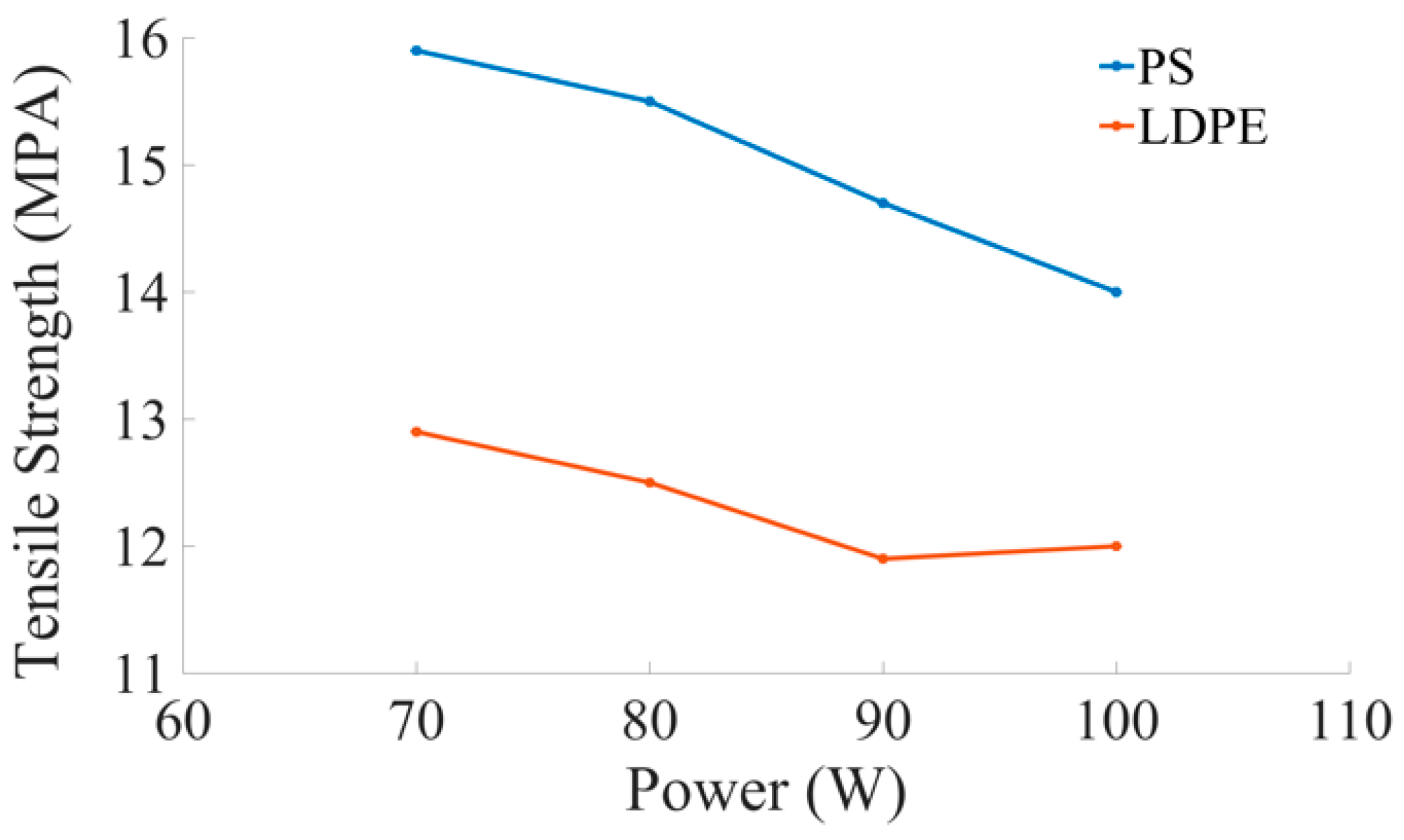
- PS material’s tensile strength decreases significantly when power is increased as compared to LDPE material, as shown in the graphical illustration in Figure 15.
6.2. Thermal Characteristics
Thermal properties of the material such as thermal expansion, thermal conductivity, heat capacity, and enthalpy exert their influence on the cut quality. Among these properties, the thermal conductivity of a material is highly dependent on its morphology. The polymeric materials usually possess low thermal conductivity, which limits their use in high-temperature applications like in heat exchangers. The more the thermal conductivity of the polymer, the greater the temperature distribution, resulting in greater MRR [67,68]. Yilbaş et al. [69] established the relationship of temperature distribution with the work material thickness. The temperature distribution diminished when the size of the workpiece decreased. Banerjee et al. [70] made a comparison of the processing of various polymers such as fluoroelastomers (FKM), polyamide 6 (PA6) and thermoplastic elastomers (TPEs) in laser cutting. TPE contained less melted volume and area than PA6, whereas FKM possessed less melted area and volume among all previously stated polymers. The working temperature was found maximum on the workpiece surface and its edges. Choudhury et al. [71] conducted an experimental study in laser cutting, and concluded that HAZ varied directly with PL and inversely with Pg, and CS. The order of increasing HAZ produced for polymeric materials like PP, PMMA, and PC follows PP > PC > PMMA [53]. Thus, the cut quality of PMMA is higher compared to PC, and PP because of less HAZ produced on the cutting edge.
6.3. Different Strategies to Improve the Cut Quality
Various polymers like Nylon PA6-T27 result in poor cutting performance while processing using a CO2 laser. Accordingly, different methods were adopted to accelerate this cut quality like doping in 2.5–10% of Nylon using organic bentonite improved the cut quality [72]. Chiou et al. [73] implemented the six sigma principles to develop and understand the methods related to the properties of cut material. These principles were utilized in the laser cutting of acrylic polymers. The examination of different process parameters was made by using an internet-based machine vision (i.e., a camera with an image processing software), and Coordinate Measuring Machine (CMM). Modest et al. [74] developed a mathematical model to scribe the thickness of the material when studying the conduction properties of the material. The material’s inner temperature was predicted and measured after its initiation by laser. As a result, the formation of grooves and temperature is slightly influenced by the thermal effects of conduction and convection. Golyshev et al. [75] inferred that the amount of energy needed in laser cutting for obtaining the least SR in the melt flow is about 26 J/mm3.
7. Applications of CO2 Laser Cutting
Laser cutting plays a significant contribution to different industrial sectors for precision work. Stepak et al. [54] performed the CO2 laser cutting of PLLA material for making tubular stents in surgical applications. Ueda et al. [76] reported the benefits of laser cutting over conventional machining techniques in terms of work accuracy, fast cutting, and inexpensive system. The CO2 laser can assist in cost reduction and an increased production rate. In another study, Bonardi et al. [77] conducted the experimental study to decompose alkoxyamine through a CO2 laser. It resulted in the polymerization initiated for benchmark methacrylate monomers which considered an irradiated area, and having the significant potential for writing applications in 3D printing.
Additionally, CO2 laser processing eliminates distortion and increases the production rate, producing optimal microscopic results [78]. Sharp et al. [79] employed a CO2 laser for the manufacturing of medical types of equipment. Ink filler was used for showing a mark. Laser cutting is widely used to machine medical and surgical types of equipment. Therefore, it can also be regarded as a lifesaver. Caiazzo et al. [8] described some of the standard applications of laser cutting, which include cellular phones, orifice drilling, inkjet heads, flat panel annealing, optical circuits, drilling angioplasty devices, and catheters balloons. A parametric investigation on different laser types was performed, and as a result, the main application areas of laser cutting include material removal, cladding, and inscribing. Mayuet et al. [80] made a comparison of laser-assisted drilling with conventional drilling and stated that the laser processed part resulted in no mechanical vibrations, cutting forces and tool wear like in traditional drilling.
Wang et al. [81] proposed an idea for a laser marker to process it at low Pg, and PL. Chryssolouris et al. [82] proposed a three-dimensional laser cutting approach for composite materials along with plastics polymers. The method involved the use of two interlinked beams for 3D cutting. These polymeric materials are used in daily life to manufacture plastic bottles. Stock et al. [83] reported the laser cutting process for CFRP material for its use in light material weight applications such as in aircraft and other instruments.
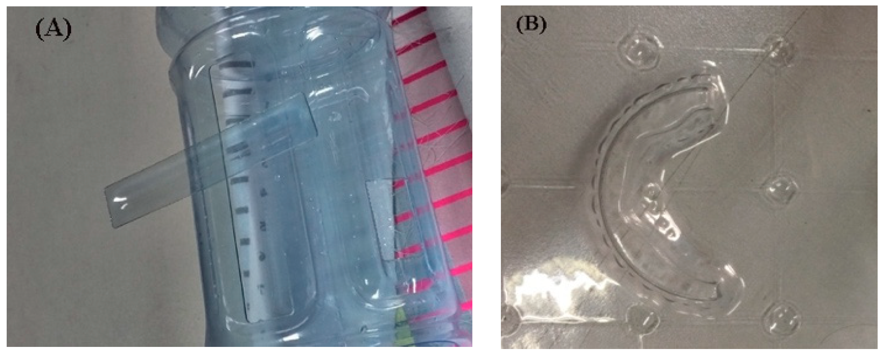
Schraft et al. [84] examined the laser cut quality by evaluating the dominance-free cancellation beam guidance component optical effects for obtaining high accuracy. The representation of a polyethylene terephthalate (PET) material cut by the CO2 laser is shown in Figure 16. Kim et al. [85] described the application of laser processing to join polymers. The authors found that the industries greatly benefited from the combination of PP, and PC when joined for household, and industrial products. However, the molecular power and adhesion forces of both PP and PC were found less. Rooks et al. [86] provided an example of three-dimensional laser cutting, which has typical applications in an assembly line of the automotive industry for cutting car sets and filling them with compounds. Genna et al. [87] reported the application of laser processing for making molds, and tools. It was found that the material’s cutting quality can be improved by clockwise cutting.
8. Conclusions and Remarks
The inspirations of using CO2 lasers in cutting different polymeric materials are undeniable for households as well as industrial applications. The present study is established to review the study of the influence of different process variables such as cutting speed (CS), laser power (PL), and assist gas pressure (Pg), pulse frequency, nozzle type and its diameter, and stand-off distance for surface roughness (SR), heat-affected zone (HAZ), kerf width (KW), dross formation, charring, and striations formation, in the CO2 laser cutting of plastic polymers. The main findings of this work include:
- Low power CO2 laser cutting possesses a significant potential to improve the cut quality in terms of SR, HAZ, and KW, dross, and striations formation.
- The reported results indicate that: (a) SR is increased as PL and CS are increased. (b) HAZ is varied directly with PL and inversely with the CS. (c) KW is varied inversely with CS. (d) Pg is found highly influential in reducing the dross formation. (e) The control of PL is considered as highly important factor to minimize the workpiece burning in terms of striations formation, charring formation, and HAZ. (f) Striation formation is significantly affected by the variations in Pg, fluctuations in PL, and workpiece vibrations. (g) The polymeric materials with high density and surface tension result in more dross formation while laser cutting. (h) As Pg is increased, the dross formation and HAZ intensity is reduced. (i) Nozzle type and its diameter are highly influenced on Pg to improve the cut quality. (j) An optimized stand-off distance assists in stable cutting, and reduces turbulence. (k) As pulse frequency is increased, then KW is reduced.
- The properties of polymeric materials (thermoplastics/thermosetting) also influence on the cut quality in laser cutting. However, the mechanical and thermal properties are highly influential compared to other characteristics.
- Low power CO2, laser cutting has shown promising results for almost all ranges of low melting materials. Therefore, it finds difficulty in processing high melt materials.
9. Shortfalls and Areas of Future Research
Previous sections were dedicated to elaborate the importance of CO2 laser cutting for polymeric materials, properties of these polymeric materials, laser cutting parameters, and different application areas. Significant work has already been done on CO2 laser cutting of polymers. Still, the following recommendations could be supposed to be the possible future research trends in laser cutting.
- Although the laser cutting variables like CS, PL, focal spot position, and Pg are comprehensively described, their combined influence on overall cut quality is still needed to be explored further
- Some of the quality characteristics like charring formation and striations formation in CO2 laser cutting are less significantly reported in the existing literature. Therefore, these should be further explored to improve the cut quality.
- The Pg imparts a significant role on the cut quality. Therefore, a suitable Pg range is needed to be calculated further by balancing the exact material requirements and the overall cut quality.
- As nozzle type and its diameter is highly influenced on Pg for cut quality. Therefore, the investigation on the design of the nozzle is yet needed to be explored further.
- The properties of polymeric materials like mechanical and thermal characteristics in the context of laser cutting are reported with an exploratory discussion. Other properties, such as optical characteristics including transmission, reflection, and absorption, are yet needed to be explored further.
- Different mathematical modeling techniques in laser cutting are yet needed to be explored to improve the cut quality.
- Some of the polymeric materials produce toxic environmental effects when burned; therefore, the environmental impacts of various thermoplastics/ thermosetting polymers in laser cutting are yet needed to be further elaborated.
CO2 laser cutting is found to be very useful in various industries, and household applications because of its consistently growing demand for a wide variety of low melting materials, especially plastic polymers. Therefore, it is still a potential research area for further investigation.
Author Contributions
R.T.M.: Conceptualization, Methodology, Validation, Formal Analysis, Investigation, Writing—Original Draft Preparation; Y.W.: Funding Acquisition, Project Administration, Supervision; M.R.: Data Curation, Software, Visualization; A.M.K.: Review & Editing; Data Curation, Validation; M.M.: Resources, Validation, Writing—Review & Editing. All authors have read and agreed to the published version of the manuscript.
Funding
The research grant is funded by (1) The National Key Research and Development Program of China (Grant No. 2019QY(Y)0502), (2) The key research and development program of shaanxi province (Grant No. 2020ZDLSF04-07), (3) the Fundamental Research Funds for the Central Universities (Grant No. 31020190502009) (4) the Innovation Platform of Biofabrication (Grant No.17SF0002).
Acknowledgments
The authors are thankful to Bone Biological Technology Co., Ltd., Xi’an, Xi’an Kong Tian Dong Li Ke Ji You Xi’an Gong Si and Shanghai Yuehua Laser Technology Co., Ltd.
Conflicts of Interest
The authors declare that they have no conflict of interest or personal relationships that could have appeared to influence the work reported in this review paper.
Nomenclature
| CMM | Coordinate measuring machine |
| CO2 | Carbon dioxide |
| CS | Cutting speed |
| CW | Continuous wave |
| DOC | Depth of cut |
| EDM | Electric discharge machining |
| HAZ | Heat-affected zone |
| HDPE | High-density polyethylene |
| Hz | Hertz |
| KW | Kerf width |
| LDPE | Low-density polyethylene |
| MRR | Material removal rate |
| PA6 | Polyamide 6 |
| PC | Polycarbonate |
| PE | Polyethylene |
| PET | Polyethylene terephthalate |
| Pg | Assist gas pressure |
| PL | Laser power |
| PMMA | Polymethyl methacrylate |
| POM | Polyoxymethylene |
| PP | Polypropylene |
| PS | Polystyrene |
| Q | Specific energy of a material |
| Rb | Laser beam radius |
| SOD | Stand-off distance |
| SR | Surface roughness |
| Tg | Glass transition temperature |
| TGA | Thermoplastic elastomers |
| ti | Interaction time |
| W | Watt |
| α | Energy absorptivity |
References
- Hao, X.; Cui, W.; Li, L.; Li, H.; Khan, A.M.; He, N. Cutting performance of textured polycrystalline diamond tools with composite lyophilic/lyophobic wettabilities. J. Mater. Process. Technol. 2018, 260, 1–8. [Google Scholar] [CrossRef]
- Khan, A.M.; Jamil, M.; Mia, M.; Pimenov, D.Y.; Gasiyarov, V.R.; Gupta, M.K.; He, N. Multi-objective optimization for grinding of AISI D2 steel with Al2O3 wheel under MQL. Materials 2018, 11, 2269. [Google Scholar] [CrossRef] [PubMed] [Green Version]
- Jamil, M.; Khan, A.M.; Hegab, H.; Gong, L.; Mia, M.; Gupta, M.K.; He, N. Effects of hybrid Al2O3-CNT nanofluids and cryogenic cooling on machining of Ti–6Al–4V. Int. J. Adv. Manuf. Technol. 2019, 102, 3895–3909. [Google Scholar] [CrossRef]
- Ahmed, N.; Darwish, S.; Alahmari, A.M. Laser ablation and laser-hybrid ablation processes: A review. Mater. Manuf. Process. 2015, 31, 1121–1142. [Google Scholar] [CrossRef]
- Ahmed, N.; Darwish, S.; Alahmari, A.M.; Salik, K. Laser ablation process competency to fabricate microchannels in titanium alloy. Mater. Manuf. Process. 2015, 30, 1290–1297. [Google Scholar] [CrossRef]
- Ahmed, N.; Darwish, S.; Alahmari, A.M.; Shar, M.A. Micro-channels by Nd:YAG laser beam machining: Fabrication, microstructures, and micro-hardness profiles. Int. J. Adv. Manuf. Technol. 2015, 85, 1955–1968. [Google Scholar] [CrossRef]
- Alahmari, A.M.; Darwish, S.; Ahmed, N. Laser beam micro-milling (LBMM) of selected aerospace alloys. Int. J. Adv. Manuf. Technol. 2016, 86, 2411–2431. [Google Scholar] [CrossRef]
- Caiazzo, F.; Curcio, F.; Daurelio, G.; Minutolo, F.M.C. Laser cutting of different polymeric plastics (PE, PP and PC) by a CO2 laser beam. J. Mater. Process. Technol. 2005, 159, 279–285. [Google Scholar] [CrossRef]
- Bîrcă, A.; Gherasim, O.; Grumezescu, V.; Grumezescu, A.M. Chapter 1—Introduction in thermoplastic and thermosetting polymers. In Materials for Biomedical Engineering; Grumezescu, V., Grumezescu, A.M., Eds.; Elsevier: Amsterdam, The Netherlands, 2019; pp. 1–28. [Google Scholar] [CrossRef]
- Tiwari, A.B.; Bajpai, J.; Saini, R.; Agrawal, P. Smart Biomaterial Devices; CRC Press: Boca Raton, FL, USA, 2016. [Google Scholar] [CrossRef]
- Ward, I.M.; Sweeney, J. Mechanical Properties of Solid Polymers; John Wiley & Sons: Hoboken, NJ, USA, 2012. [Google Scholar]
- Fox, T.G.; Flory, P.J. The glass temperature and related properties of polystyrene. Influence of molecular weight. J. Polym. Sci. 1954, 14, 315–319. [Google Scholar] [CrossRef]
- Massy, J. Thermoplastic and thermosetting polymers. In A Little Book about BIG Chemistry: The Story of Man-Made Polymers; Massy, J., Ed.; Springer International Publishing: Cham, Switzerland, 2017; pp. 19–26. [Google Scholar] [CrossRef]
- Radlmaier, V.; Heckel, C.; Winnacker, M.; Erber, A.; Koerber, H. Effects of thermal cycling on polyamides during processing. Thermochim. Acta 2017, 648, 44–51. [Google Scholar] [CrossRef]
- Oliveira, T.A.; Oliveira, R.R.; Barbosa, R.; Azevedo, J.B.; Alves, T.S. Effect of reprocessing cycles on the degradation of PP/PBAT-thermoplastic starch blends. Carbohydr. Polym. 2017, 168, 52–60. [Google Scholar] [CrossRef]
- Ginjupalli, K.; Shavi, G.V.; Averineni, R.K.; Bhat, M.; Udupa, N.; Nagaraja Upadhya, P. Poly(α-hydroxy acid) based polymers: A review on material and degradation aspects. Polym. Degrad. Stab. 2017, 144, 520–535. [Google Scholar] [CrossRef]
- Schmidt, A.X. Principles of High-Polymer Theory AntiPractice; McGraw-Hill: New York, NY, USA, 1948. [Google Scholar]
- Finch, C.A. Polymer handbook: Third edition. Br. Polym. J. 1990, 23, 277–280. [Google Scholar] [CrossRef]
- Buchdahl, R. Mechanical properties of polymers and composites. J. Polym. Sci. Polym. Lett. Ed. 1975, 13, 120–121. [Google Scholar] [CrossRef]
- Young, R.J. Properties of polymers. Polym. Int. 1991, 26, 59–60. [Google Scholar] [CrossRef]
- Schober, A.; Musiol, J.; Daub, R.; Feil, J.; Zaeh, M.F. Experimental investigation of the cutting front angle during remote fusion cutting. Phys. Procedia 2012, 39, 204–212. [Google Scholar] [CrossRef] [Green Version]
- Powell, J. CO2 Laser Cutting, 2nd ed.; Springer: Heidelberg, Germany; New York, NY, USA, 1998. [Google Scholar]
- Huang, Y.; Liu, S.; Yang, W.; Yu, C. Surface roughness analysis and improvement of PMMA-based microfluidic chip chambers by CO2 laser cutting. Appl. Surf. Sci. 2010, 256, 1675–1678. [Google Scholar] [CrossRef]
- Ion, J.C. Laser Processing of Engineering Materials; Elsevier Butterworth Heinemann: Oxford, UK, 2005. [Google Scholar]
- Rehman, M.; Khan, S.A.; Naveed, R. Parametric optimization in wire electric discharge machining of DC53 steel using gamma phase coated wire. J. Mech. Sci. Technol. 2020, 34, 2767–2773. [Google Scholar] [CrossRef]
- Eltawahni, H.A.; Olabi, A.G.; Benyounis, K.Y. Assessment and optimization of CO2 laser cutting process of PMMA. In Proceedings of the International Conference on Advances in Materials and Processing Technologies, AMPT2010, Paris, France, 24–27 October 2010; pp. 1553–1558. [Google Scholar]
- Yilbas, B.S. Laser cutting quality assessment and thermal efficiency analysis. J. Mater. Process. Technol. 2004, 155–156, 2106–2115. [Google Scholar] [CrossRef]
- Sheng, P.; Cai, L.H. Model-based path planning for laser cutting of curved trajectories. Int. J. Mach. Tools Manuf. 1996, 36, 739–754. [Google Scholar] [CrossRef]
- Al-Sulaiman, F.A.; Yilbas, B.S.; Ahsan, M. CO2 laser cutting of a carbon/carbon multi-lamelled plain-weave structure. J. Mater. Process. Technol. 2006, 173, 345–351. [Google Scholar] [CrossRef]
- Hossain, A.; Nukman, Y.; Sifullah, A.M. Effect of process parameter in laser cutting of PMMA sheet and ANFIS modelling for online control. In Proceedings of the 3rd International Conference on Mechanics and Mechatronics Research, ICMMR 2016, Chongqing, China, 15–17 June 2016. [Google Scholar]
- Gross, M.S.; Neill, W.O. New aspects of melt flow phenomena through narrow kerfs. J. Phys. D Appl. Phys. 2007, 40, 1201. [Google Scholar] [CrossRef]
- Keles, O.; Oner, U. A study of the laser cutting process: Influence of laser power and cutting speed on cut quality. Lasers Eng. 2010, 20, 319–327. [Google Scholar]
- Quintero, F.; Riveiro, A.; Lusquiños, F.; Comesaña, R.; Pou, J. Feasibility study on laser cutting of phenolic resin boards. Phys. Procedia 2011, 12, 578–583. [Google Scholar] [CrossRef] [Green Version]
- Tamrin, K.F.; Moghadasi, K.; Sheikh, N.A. Experimental and numerical investigation on multi-pass laser cutting of natural fibre composite. Int. J. Adv. Manuf. Technol. 2020, 107, 1483–1504. [Google Scholar] [CrossRef]
- Ghany, K.A.; Newishy, M. Cutting of 1.2 mm thick austenitic stainless steel sheet using pulsed and CW Nd:YAG laser. J. Mater. Process. Technol. 2005, 168, 438–447. [Google Scholar] [CrossRef]
- Kannatey-Asibn, E. Principles of Laser Materials Processing; John Wiley & Sons Inc.: Hoboken, NJ, USA, 2009. [Google Scholar]
- Yilbas, B.S. The analysis of CO2 laser cutting. Proc. Inst. Mech. Eng. 1996, 211 Pt B, 223–232. [Google Scholar] [CrossRef]
- Schuöcker, D.; Schuöcker, G. Dynamic phenomena and quality defects in laser cutting. In Proceedings of the 9th International Symposium on High Power Laser Ablation 2012, HPLA 2012, Santa Fe, NM, USA, 30 April–3 May; pp. 317–324.
- Abrão, A.M.; Faria, P.E.; Rubio, J.C.C.; Reis, P.; Davim, J.P. Drilling of fiber reinforced plastics: A review. J. Mater. Process. Technol. 2007, 186, 1–7. [Google Scholar] [CrossRef]
- Yilbaş, B.S. Experimental investigation into CO2 laser cutting parameters. J. Mater. Process. Technol. 1996, 58, 323–330. [Google Scholar] [CrossRef]
- Ohkubo, T.; Tsukamoto, M.; Sato, Y. Numerical simulation of combustion effects during laser processing of carbon fiber reinforced plastics. Appl. Phys. A 2016, 122. [Google Scholar] [CrossRef]
- Akitt, D.R.; Seguin, H.J.J.; Cervenan, M.R.; Nikumb, S.K. Electronic mode and power control of a high-power CO2 laser. IEEE J. Quantum Electron. 1990, 26, 1413–1417. [Google Scholar] [CrossRef]
- Eltawahni, H.A.; Olabi, A.G.; Benyounis, K.Y. Effect of process parameters and optimization of CO2 laser cutting of ultra high-performance polyethylene. Mater. Des. 2010, 31, 4029–4038. [Google Scholar] [CrossRef] [Green Version]
- Goeke, A.; Emmelmann, C. Influence of laser cutting parameters on CFRP part quality. Phys. Procedia 2010, 5, 253–258. [Google Scholar] [CrossRef] [Green Version]
- Jeffrey Kuo, C.-F.; Chiu, H.-Y.; Syu, S.-S.; Huy Vu, Q. The CO2 laser parameter optimization design and practical verification for a touch panel conductive film. Opt. Lasers Eng. 2014, 52, 250–260. [Google Scholar] [CrossRef]
- Zhou, B.H.; Mahdavian, S.M. Experimental and theoretical analyses of cutting nonmetallic materials by low power CO2-laser. J. Mater. Process. Technol. 2004, 146, 188–192. [Google Scholar] [CrossRef]
- Vishnulal, R.K.; Govindan, P.; Vipindas, M.P. Laser machining of polymer materials—Experimental investigations—Process challenges and strategies. In Proceedings of the International Conference on Emerging Trends in Engineering (ICETE), Karnataka, India, 22–23 December 2020; pp. 653–661. [Google Scholar] [CrossRef]
- Hashemzadeh, M.; Voisey, K.T.; Kazerooni, M. The effects of low-frequency workpiece vibration on low-power CO2 laser cutting of PMMA: An experimental investigation. Int. J. Adv. Manuf. Technol. 2012, 63, 33–40. [Google Scholar] [CrossRef]
- Bunting, K.A.; Cornfield, G. Toward a general theory of cutting: A relationship between the incident power density and the cut speed. J. Heat. Transfer. Trans. ASME 1975, 97, 116–122. [Google Scholar] [CrossRef]
- Pietro, P.D.; Yao, Y.L.; Jeromin, A. Quality optimisation for laser machining under transient conditions. J. Mater. Process. Technol. 2000, 97, 158–167. [Google Scholar] [CrossRef]
- Di Pietro, P.; Yao, Y.L. A numerical investigation into cutting front mobility in CO2 laser cutting. Int. J. Mach. Tools Manuf. 1995, 35, 673–688. [Google Scholar] [CrossRef]
- Karimzad Ghavidel, A.; Shabgard, M.; Biglari, H. Microscopic and mechanical properties of semi-crystalline and amorphous polymeric parts produced by laser cutting. J. Appl. Polym. Sci. 2016, 133. [Google Scholar] [CrossRef]
- Davim, J.P.; Barricas, N.; Conceição, M.; Oliveira, C. Some experimental studies on CO2 laser cutting quality of polymeric materials. J. Mater. Process. Technol. 2008, 198, 99–104. [Google Scholar] [CrossRef]
- Stępak, B.; Antończak, A.J.; Bartkowiak-Jowsa, M.; Filipiak, J.; Pezowicz, C.; Abramski, K.M. Fabrication of a polymer-based biodegradable stent using a CO2 laser. Arch. Civil Mech. Eng. 2014, 14, 317–326. [Google Scholar] [CrossRef]
- Sahin, A.Z.; Yilbas, B.S.; Ayar, T. Laser cutting efficiency and quality assessments. In Comprehensive Materials Processing; Elsevier Ltd.: Amsterdam, The Netherlands, 2014; Volume 9, pp. 235–242. [Google Scholar]
- Sahin, A.Z.; Yilbas, B.S.; Ayar, T. Laser cutting of ceramic and thermal efficiency analysis. In Proceedings of the 14th International Conference on Advances in Materials and Processing Technologies, AMPT 2011, Istanbul, Turkey, 13–16 July 2011; Volume 445, pp. 400–405. [Google Scholar]
- Madić, M.; Radovanović, M.; Manić, M.; Trajanović, M. Optimization of CO2 laser cutting process using taguchi and dual response surface methodology. Tribol. Ind. 2014, 36, 236–243. [Google Scholar]
- Man, H.C.; Duan, J.; Yue, T.M. Dynamic characteristics of gas jets from subsonic and supersonic nozzles for high pressure gas laser cutting. Opt. Laser Technol. 1998, 30, 497–509. [Google Scholar] [CrossRef]
- Man, H.C.; Duan, J.; Yue, T.M. Analysis of the dynamic characteristics of gas flow inside a laser cut kerf under high cut-assist gas pressure. J. Phys. D Appl. Phys. 1999, 32, 1469–1477. [Google Scholar] [CrossRef]
- Chen, S.-L. The effects of high-pressure assistant-gas flow on high-power CO2 laser cutting. J. Mater. Process. Technol. 1999, 88, 57–66. [Google Scholar] [CrossRef]
- Riveiro, A.; Quintero, F.; Boutinguiza, M.; Del Val, J.; Comesaña, R.; Lusquiños, F.; Pou, J. Laser cutting: A review on the influence of assist gas. Materials 2019, 12, 157. [Google Scholar] [CrossRef] [Green Version]
- Peter, A.A.; Margarita, G.B. CW CO2 Laser Cutting of Plastics. In Proceedings of the XIth International Symposium on Gas Flow and Chemical Lasers and High-Power Laser Conference, Edinburgh, UK, 25–30 August 1996; Denis, R.H., Howard, J.B., Eds.; Society of Photo Optical: Bellingham, WA, USA, 1997. [Google Scholar]
- Russo Spena, P.; De Maddis, M.; Lombardi, F. Cut quality assessment of CO2 laser cutting of twinning-induced plasticity steel sheets. Proc. Inst. Mech. Eng. Part B J. Eng. Manuf. 2014, 229, 3–19. [Google Scholar] [CrossRef]
- Badoniya, P. CO2 laser cutting of different materials—A review. Int. Res. J. Eng. Technol. (IRJET) 2018, 5, 2103–2115. [Google Scholar]
- Che, D.; Saxena, I.; Han, P.; Guo, P.; Ehmann, K.F. Machining of carbon fiber reinforced plastics/polymers: A literature review. J. Manuf. Sci. Eng. 2014, 136. [Google Scholar] [CrossRef]
- Radek, N.; Pietraszek, J.; Gądek-Moszczak, A.; Orman, Ł.J.; Szczotok, A. The morphology and mechanical properties of ESD coatings before and after laser beam machining. Materials 2020, 13, 2331. [Google Scholar] [CrossRef] [PubMed]
- Nunes dos Santos, W.; Augusto Marcondes Agnelli, J.; Mummery, P.; Wallwork, A. Effect of recycling on the thermal properties of polymers. Polym. Test. 2007, 26, 216–221. [Google Scholar] [CrossRef]
- Rahaman, A.; Kar, A.; Yu, X. Thermal effects of ultrafast laser interaction with polypropylene. Opt. Express 2019, 27, 5764–5783. [Google Scholar] [CrossRef] [PubMed]
- Yilbaş, B.S.; Sahin, A.Z. Oxygen assisted laser cutting mechanism—A laminar boundary layer approach including the combustion process. Opt. Laser Technol. 1995, 27, 175–184. [Google Scholar] [CrossRef]
- Banerjee, S.S.; Bhowmick, A.K. Experimental study on the CO2 laser cutting of novel polyamide 6/fluoroelastomer thermoplastic elastomeric blends. Rubber Chem. Technol. 2015, 88, 125–137. [Google Scholar] [CrossRef]
- Choudhury, I.A.; Shirley, S. Laser cutting of polymeric materials: An experimental investigation. Opt. Laser Technol. 2010, 42, 503–508. [Google Scholar] [CrossRef]
- Antończak, A.J.; Nowak, M.; Szustakiewicz, K.; Pigłowski, J.; Abramski, K.M. The influence of organobentonite clay on CO2 laser grooving of nylon 6 composites. Int. J. Adv. Manuf. Technol. 2013, 69, 1389–1401. [Google Scholar] [CrossRef] [Green Version]
- Chiou, R.; Mauk, M.; Agarwal, S.; Yang, Y.T. Development of E-quality laboratory modules for use in engineering quality control courses. In Proceedings of the 2009 ASEE Annual Conference and Exposition, Austin, TX, USA, 14–17 June 2009. [Google Scholar]
- Modest, M.F. Laser through-cutting and drilling models for ablating/decomposing materials. J. Laser Appl. 1997, 9, 137–145. [Google Scholar] [CrossRef]
- Golyshev, A.A.; Orishich, A.M.; Shulyatyev, V.B. Energetics of the multi-phase fluid flow in a narrow kerf in laser cutting conditions. In Proceedings of the 18th International Conference on the Methods of Aerophysical Research, ICMAR 2016, Perm, Russia, 27 June–3 July 2016. [Google Scholar]
- Ueda, M.; Saitoh, Y.; Hachisuka, H.; Ishigaki, H.; Gokoh, Y.; Mantani, H. Studies on CO2 laser marking. Opt. Lasers Eng. 1990, 12, 245–249. [Google Scholar] [CrossRef]
- Bonardi, A.H.; Dumur, F.; Gigmes, D.; Xu, Y.Y.; Lalevee, J. Light-induced thermal decomposition of alkoxyamines upon infrared CO2 laser: Toward spatially controlled polymerization of methacrylates in laser write experiments. ACS Omega 2020, 5, 3043–3046. [Google Scholar] [CrossRef] [Green Version]
- Betforte, D.A. Industrial applications for high-power lasers—An overview. Proc. SPIE Int. Soc. Opt. Eng. 1981, 270, 66–72. [Google Scholar] [CrossRef]
- Sharp, M.C. Laser processing of medical devices. In Biophotonics for Medical Applications; Elsevier Inc.: Amsterdam, The Netherlands, 2015; pp. 79–98. [Google Scholar] [CrossRef]
- Mayuet Ares, P.F.; Vazquez Martinez, J.M.; Marcos Barcena, M.; Gamez, A.J. Experimental study of macro and microgeometric defects in drilled carbon fiber reinforced plastics by laser beam machining. Materials 2018, 11, 1466. [Google Scholar] [CrossRef] [PubMed] [Green Version]
- Wang, S.-C.; Lee, C.-Y.; Chen, H.-P. Thermoplastic microchannel fabrication using carbon dioxide laser ablation. J. Chromatogr. A 2006, 1111, 252–257. [Google Scholar] [CrossRef] [PubMed]
- Chryssolouris, G.; Sheng, P.; Choi, W.C. Three-dimensional laser machining of composite materials. J. Eng. Mater. Technol. Trans. ASME 1990, 112, 387–392. [Google Scholar] [CrossRef]
- Stock, J.; Zaeh, M.F.; Conrad, M. Remote laser cutting of CFRP: Improvements in the cut surface. Phys. Procedia 2012, 39, 161–170. [Google Scholar] [CrossRef] [Green Version]
- Schraft, R.D.; Hardock, G.; Koenig, M. Easier in the hands of a robot. New external beam control system for cutting and welding with CO2 lasers. VDI-Zeitschrift 1989, 131, 84–91. [Google Scholar]
- Kim, D.J.; Jeon, I.R.; Park, H.Y.; Seo, K.H. Modification of polypropylene for improving the laser transmission weldability to polycarbonate. Polymer 2013, 37, 753–763. [Google Scholar] [CrossRef] [Green Version]
- Rooks, B. Laser processing of plastics. Ind. Robot Int. J. 2004, 31, 338–342. [Google Scholar] [CrossRef]
- Genna, S.; Leone, C.; Lopresto, V.; Tagliaferri, V. An experimental study on the surface mechanisms formation during the laser milling of PMMA. Polym. Compos. 2015, 36, 1063–1071. [Google Scholar] [CrossRef]
Figure 1.
Fusion cutting mechanism [21].
Figure 1.
Fusion cutting mechanism [21].

Figure 2.
Polymethyl methacrylate (PMMA) laser cutting using vaporization [23].
Figure 2.
Polymethyl methacrylate (PMMA) laser cutting using vaporization [23].

Figure 3.
Schematic illustration of the cut material and its kerf formation (A,B): Schematic illustration of kerf and kerf width, (C): Physical representation of KW, and (D): Microscopic analysis of kerf width.
Figure 3.
Schematic illustration of the cut material and its kerf formation (A,B): Schematic illustration of kerf and kerf width, (C): Physical representation of KW, and (D): Microscopic analysis of kerf width.

Figure 4.
A schematic diagram for striation formation during the laser cutting process [35].
Figure 4.
A schematic diagram for striation formation during the laser cutting process [35].

Figure 5.
Graphical trend to show the preheated temperature effect on surface roughness (SR) [23].
Figure 5.
Graphical trend to show the preheated temperature effect on surface roughness (SR) [23].

Figure 6.
Representation of Dross formation during laser cutting.

Figure 7.
Heat-affected zone (HAZ) area of the laser cut material.

Figure 8.
Cause and effect diagram to elaborate on the effect of different input parameters on output responses [44].
Figure 8.
Cause and effect diagram to elaborate on the effect of different input parameters on output responses [44].

Figure 9.
Detailed representation of the process of CO2 laser cutting, cutting variables, and output responses.
Figure 9.
Detailed representation of the process of CO2 laser cutting, cutting variables, and output responses.

Figure 10.
Parametric trends for CS and depth of cut (DOC) at different power ratings in PMMA [46].
Figure 10.
Parametric trends for CS and depth of cut (DOC) at different power ratings in PMMA [46].

Figure 11.
Parametric trends for CS and the thickness at different power ratings for PE and PP (A): Graphical trends for CS and thickness for PE at different power, (B): Illustration of steep curve to describe the relationship between CS and thickness, (C): Pictorial representation of PE cut part, (D): Graphical trends for CS and thickness for PE at different power, (E): Illustration of steep curve to describe the relationship between CS and thickness, and (F): Pictorial representation of PP cut part [8].

Figure 12.
Parametric trends for laser CS, HAZ for PS, LDPE, and PMMA at different power ratings (A): Graphical illustration to show the influence of cutting velocity on HAZ, (B) Indication of pointed part of (A), (C): Pictorial representation of one of the cut parts among PS and LDPE, (D): Relationship between cutting velocity and HAZ at different power for PMMA, (E): Indication of maximum HAZ from (D), and (F): Pictorial representation of the cut part with maximum HAZ [52,53].

Figure 13.
Parametric trends for PL and CS for PS, LDPE, PE, PP, and PC at different power ratings (A): Graphical illustration to show the influence of laser power on HAZ for PS and LDPE, (B) Indication of pointed part of (A), (C): Pictorial representation of one of the cut parts among PS and LDPE, (D): Relationship between laser power and cutting speed at same thickness of 5 mm for PE, PP, and PC, (E): Indication of pointed part from (D), (F): Pictorial representation of one of the cut parts among PE, PP, and PC (G–I): Microscopic examination of cut part at 100×, 200×, and 500× [8,52].

Figure 14.
(A,B): Schematic representation of the focal point position/standoff distance in laser cutting, (C) Physical view of the cut part at more standoff distance, (D): Microscopic examination of cut part at high standoff distance.
Figure 14.
(A,B): Schematic representation of the focal point position/standoff distance in laser cutting, (C) Physical view of the cut part at more standoff distance, (D): Microscopic examination of cut part at high standoff distance.

Figure 15.
Parametric trend to indicate the effect of the power on tensile strength break for PS and LDPE [52].
Figure 15.
Parametric trend to indicate the effect of the power on tensile strength break for PS and LDPE [52].

Figure 16.
(A,B): Physical demonstration to show the laser cutting of polyethylene terephthalate (PET) at different parametric settings.
Figure 16.
(A,B): Physical demonstration to show the laser cutting of polyethylene terephthalate (PET) at different parametric settings.


Table 1.
Cutting parameter levels for polyethylene (PE), polypropylene (PP), and polycarbonate (PC) in the fusion cutting mechanism [22].
Table 1.
Cutting parameter levels for polyethylene (PE), polypropylene (PP), and polycarbonate (PC) in the fusion cutting mechanism [22].
| Material | Thickness (mm) | Laser Power (PL, W) | Cutting Speed (CS, m/min) |
|---|---|---|---|
| PE | 1 | 500 | 11 |
| 3 | 500 | 2.2 | |
| 6 | 500 | 1 | |
| 9 | 500 | 0.5 | |
| PP | 1 | 500 | 17 |
| 3 | 500 | 4 | |
| 6 | 500 | 1.6 | |
| 9 | 500 | 0.9 | |
| PC | 1 | 500 | 21 |
| 3 | 500 | 5 | |
| 6 | 500 | 2.1 | |
| 9 | 500 | 1.1 |
Note: The assist gas pressure (Pg) ranges from 1 to 4 bar, and the nozzle diameter ranges from 1 to 2 mm in fusion cutting.
Table 2.
Cutting parameter levels for PMMA in the vaporization cutting mechanism [22].
Table 2.
Cutting parameter levels for PMMA in the vaporization cutting mechanism [22].
| Material | Thickness (mm) | PL (W) | CS (m/min) |
|---|---|---|---|
| PMMA | 1 | 500 | 35 |
| 3 | 500 | 8 | |
| 6 | 500 | 3.5 | |
| 9 | 500 | 1.9 |
Note: Pg usually ranges from 1 to 4 bar for PMMA and nozzle diameters from 1 to 2 mm in the vaporization cutting mechanism. However, if the glossy edge is required, the Pg may be dropped below 0.25 bar.
Table 3.
Cutting parameter levels for selected materials in the chemical degradation mechanism [22].
Table 3.
Cutting parameter levels for selected materials in the chemical degradation mechanism [22].
| Material | Thickness (mm) | PL (W) | CS (m/min) |
|---|---|---|---|
| Rubber | 3 | 400 | 4 |
| 6 | 400 | 1.6 | |
| 9 | 400 | 0.9 | |
| Rubber (carbon-filled, black) | 3 | 400 | 3 |
| 6 | 400 | 1.2 | |
| 9 | 400 | 0.35 |
Note: Pg usually ranges from 3 to 10 bar and nozzle diameters from 1 to 2 mm in chemical degradation.
Table 4.
Properties values for different polymers [45].
Table 4.
Properties values for different polymers [45].
| Material | Density (kg/m3) | Q (kJ/g) | B | ω |
|---|---|---|---|---|
| PMMA | 1180 | 2 | 0.415 | 0.7 |
| Rubber | 1300 | 2.1 | 0.791 | 0.83 |
© 2020 by the authors. Licensee MDPI, Basel, Switzerland. This article is an open access article distributed under the terms and conditions of the Creative Commons Attribution (CC BY) license (http://creativecommons.org/licenses/by/4.0/).
Share and Cite
MDPI and ACS Style
Mushtaq, R.T.; Wang, Y.; Rehman, M.; Khan, A.M.; Mia, M. State-Of-The-Art and Trends in CO2 Laser Cutting of Polymeric Materials—A Review. Materials 2020, 13, 3839. https://doi.org/10.3390/ma13173839
AMA Style
Mushtaq RT, Wang Y, Rehman M, Khan AM, Mia M. State-Of-The-Art and Trends in CO2 Laser Cutting of Polymeric Materials—A Review. Materials. 2020; 13(17):3839. https://doi.org/10.3390/ma13173839
Chicago/Turabian StyleMushtaq, Ray Tahir, Yanen Wang, Mudassar Rehman, Aqib Mashood Khan, and Mozammel Mia. 2020. "State-Of-The-Art and Trends in CO2 Laser Cutting of Polymeric Materials—A Review" Materials 13, no. 17: 3839. https://doi.org/10.3390/ma13173839
Note that from the first issue of 2016, this journal uses article numbers instead of page numbers. See further details here.