Frictional Behaviour of Composite Anodized Layers on Aluminium Alloys
by
 , , , and
Radomir Atraszkiewicz
1,* ,
,
Marcin Makówka
1,
Łukasz Kołodziejczyk
1,
Bartłomiej Januszewicz
1 and
and
Jan Sucharkiewicz
2 1
Institute of Materials Science and Engineering, Lodz University of Technology, Stefanowskiego 1/15, 90-924 Lodz, Poland
2
ELBIT Rp., 3th Kwietnia 21, 41-253 Czeladz, Poland
*
Author to whom correspondence should be addressed.
Materials 2020, 13(17), 3747; https://doi.org/10.3390/ma13173747
Submission received: 1 July 2020
/
Revised: 19 August 2020
/
Accepted: 21 August 2020
/
Published: 24 August 2020
Abstract
:Three variants of the micro arc oxidation (MAO) technique have been used to treat a 2017A alloy surface. The first variant was a pure anodized layer, the second an anodized layer with SiC embedded nanoparticles and the third an anodized layer with Si3N4 nanoparticles. Tribological tests were performed for all variants, on three samples for every case. Friction coefficients and wear rates were calculated on the basis of experiments. The pure anodized layer manifested friction coefficient values within the range of 0.48 ÷ 0.52 and a wear rate in the range ~10−15 m3N−1m−1. SiC nanoparticles improved the tribological properties of the layer, as indicated by a reduction of the friction coefficient values to the range of 0.20 ÷ 0.26 with preserved very high resistance against wear (wear rate ~10−15 m3N−1m−1). Si3N4 particles embedded in anodized layer deteriorated the tribological properties, with a reduction in the resistance against fatigue and wear, intensification of friction forces and a change in the nature of friction contact behavior to more abrasive-like nature (friction coefficients ranging from 0.4 to 0.6 and wear rates ~10−14 m3N−1m−1).
1. Introduction
Anodizing of aluminium is mainly used to improve the tribological properties, hardness and corrosion resistance of the layered materials [1]. Anodic layers may be potentially used to protect 3D printed aluminium alloys [2,3,4,5], improve the corrosion behaviour [6] of select laser-melted aluminium alloys and protect aluminium welds [7,8].
There are many methods of producing anodized layers on aluminium alloys, from methods based on acid baths, through sol-gel technologies [9,10] to methods using high electrolytic treatment potentials, causing the presence of plasma (plasma electrolytic oxidation — PEO) or micro-arc discharges (micro arc oxidation — MAO) [11,12,13,14,15,16].
MAO methods have become an interesting solution for creating anodic layers on aluminium alloys, due to the fact that anodized layers are established with a competitive phenomenon of their dissolution by micro-discharges causing local melting of the oxide and its conversion into α-Al2O3 or γ-Al2O3 type phases, which translates directly into high operational properties of the layer. This process can be easily parameterized in terms of the proportion of individual phases and the degree of porosity [17,18].
The modification of layers with the aid of MAO methods by enriching baths with nanoparticles or covering anodized layers with non-metallic compounds is, from a tribological properties point of view, also interesting. Research in this field of work is based largely on the introduction of TiC or polytetrafluoroethylene (PTFE) nanoparticles, however, there are also solutions based on DLC (Diamond-like carbon) coatings [19,20,21,22,23,24,25].
An interesting solution, that also appeared in the field of doping anodized layers, used silicon-based compounds (SiC), but in this case the traditionally produced oxide layers were also enriched with PTFE [25]. That allowed to low friction coefficients (0.14) to be obtained while maintaining, however, low hardness of the layers (429 HV).
The solution proposed in this study is a hybrid method of composite anodized layers plasma treatment enriched with silicon-based nanoparticles (SiC, Si3N4). While in the case of silicon nitride, no beneficial effect of the nanoparticles was observed, doping with silicon carbide showed a reduction in the friction coefficient relative to pure oxide layers due to, among other causes, the reconstruction of the aluminium oxide structure.
2. Materials and Methods
2.1. Sample Preparation
The tests were carried out for set of disk samples made of the same base material aluminium alloy 2017A ASTM standard, chemical composition and main properties (presented in Table 1).
The method used for aluminium alloy treatment was micro-arc discharges (MAO) [13] with the parameters listed in Table 2.
Anodizing was carried out directly without any degreasing and activation processes and the bath temperature did not exceed 12 °C [21]. The bath was agitated during the anodizing process. Compressed air was used to mix the bath and special jet nozzles were used. The nozzles eliminate turbulent and uneven mixing with air that can cause the so-called Dead zones, where the solution is poorly mixed or mixed without mixing, which greatly improves anodizing decomposition and coating quality.
The following sets of samples were prepared for testing:
- (1)
- oxidized to a case depth of 10 µm,
- (2)
- oxidized to a case depth of 10 µm in a bath with 2 wt.% of SiC admixture,
- (3)
- oxidized to a case depth of 10 µm in a bath with 2 wt.% of Si3N4 admixture.
The grain size of the SiC and Si3N4 powder added into the electrolyte medium was <250 nm.
2.2. Mechanical Properties
Hardness of the anodized layers was determined using nanoindentation technique on a Nano Indenter G200 system (KLA Corporation, 3 Technology Drive, Milpitas, CA 95035, USA). For nanoindentation a diamond Berkovich tip was used. The tip shape was calibrated by conducting experiments on a fused silica standard and data were analysed using the Oliver and Pharr [26] approach. Initially, hardness and modulus depth profile tests were performed using the continuous stiffness measurement mode. However, due to the high porosity of the material and abundant chipping, the obtained results were unreliable. For this reason, it was necessary to conduct the tests on the cross-section areas using the classic (basic) nanoindentation mode. The choice of the location for the measurements was carried out with built-in optical microscopy system at 800× magnification. All tests were performed under ambient conditions at maximum load of 3 mN.
2.3. Phase Composition Analysis of the Anodized Surface
The phase composition analysis was made by the X-Ray diffraction (XRD) method using an Empyrean diffractometer (Panalytical Empyrean, Almeo, Netherlands) working with Co Kα radiation (λ = 0.17903 nm). The X-ray source worked at accelerating voltage of 40 kV and with current value of 40 mA. A five axis X-Y-Z-Phi-Chi stage was used. For phase analysis the incident beam optics consisted of parallel beam x-ray mirror for Co radiation with 5 mm mask, anti-scatter slit 1.4 mm and Soller slits 0.04 rad was used. Scattered beam optics consisted of parallel plate collimator of divergence 0.18 deg, Soller slits 0.04 rad and proportional point Xe detector. Scan range was from 10 to 150 degrees 2Theta with 0.05 deg step size. Time per step was set to 1 s. Analysis of diffraction patterns were made with use of High Score Plus software (ver. 3.0 e, Panalytical Empyrean, Almeo, Netherlands) and ICCD PDF 4+ database. X-ray diffraction analysis was carried out for all variants of produced layers in order to check which phases are present in the layers after the anodizing process.
2.4. Tribological Properties
Tribological properties of the anodized substrates were investigated with the use of pin-on-disc technique, using an yttria-stabilized zirconia ball of 6.4 mm in diameter as a counterbody. For that purpose, a high temperature THT tribometer (CSM) was applied. Relative humidity (RH) and sample temperature (T) were continuously recorded during friction experiments.
For statistics purposes, tribological tests were performed on three different samples treated in one galvanizing run. Wear track profiles after friction tests were recorded with a use of a T-1000 profilometer (Jenoptik Hommel Etamic, Jena, Germany) with at least three wear track profile measurements registered for each friction couple. The length of the measurement segment was 4.8 mm, the measurement range of the wear track depth was 80 µm and the apex (radius of the tip—2 µm) of the indenter always traversed the wear track perpendicular to the track tangent. Wear analysis for the layers against a zirconia counterpart was also carried out after friction test and specific wear rate of the layers was then evaluated according to Archard’s equation [27] on the basis of the wear track depth profiles and the total sliding distance.
3. Results and Discussion
3.1. Mechanical Properties Results
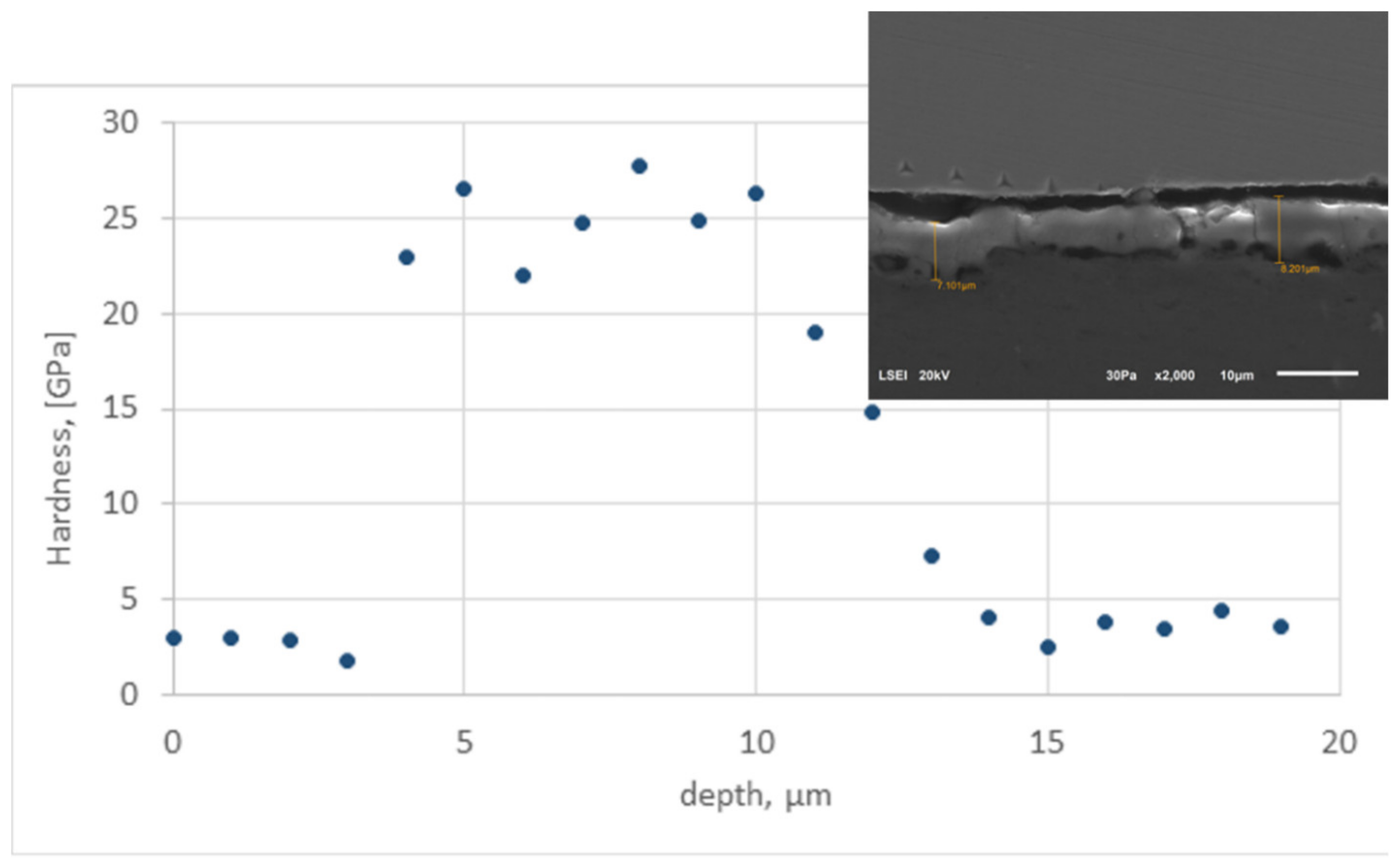
The tests were carried out on a cross-section area. Figure 1 shows the distribution of hardness results depending on the measurement location in 10 µm thick anodized layer obtained at nanoindentation load of 3 mN (indents were made across three areas: spacer made of stainless steel, anodized layer and aluminium alloy substrate, respectively). Presented hardness distributions are representative for all MAO process sets, the SiC and Si3N4 additives in the anodized layer did not significantly change the selected mechanical properties.
The hardness of the 10 µm thick anodized layer presented in Figure 1 ranged from 21 GPa to 27 GPa (the beginning of the depth profile, its first 4 points, shows the hardness values for the spacer). It is possible to observe a significant increase in hardness (more than 10 GPa) in relation to the aluminium alloy, for which the maximum obtained hardness is 5 GPa. Visible variations of the hardness results for both, layer and substrate can be attributed to porous structure.
3.2. Phase Composition Results
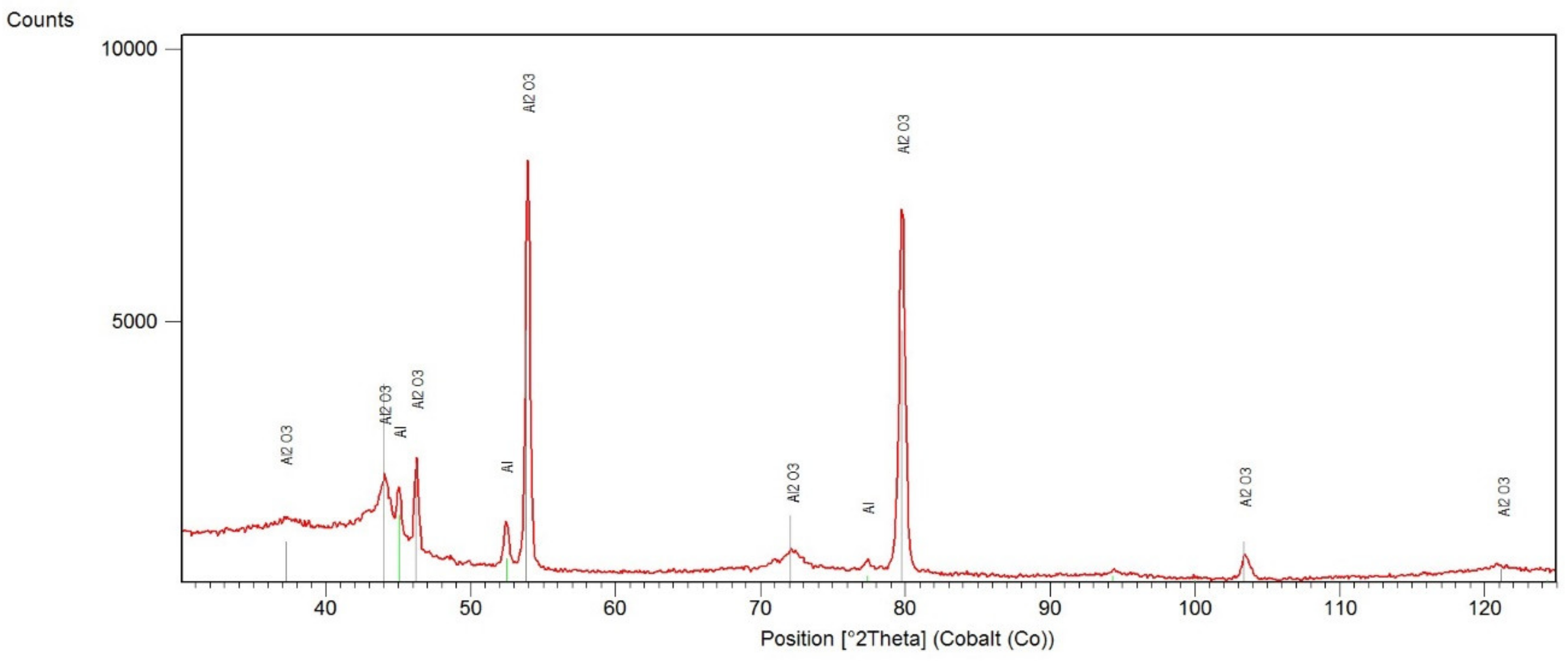
The analysis of XRD diffraction patterns of the pure anodized layer (Figure 2) revealed the presence of two main phases: γ-Al2O3 (ICDD reference: 00-010-0425) and A1 (ICDD reference: 04-016-4853). That is typical combination of phases after MAO process.
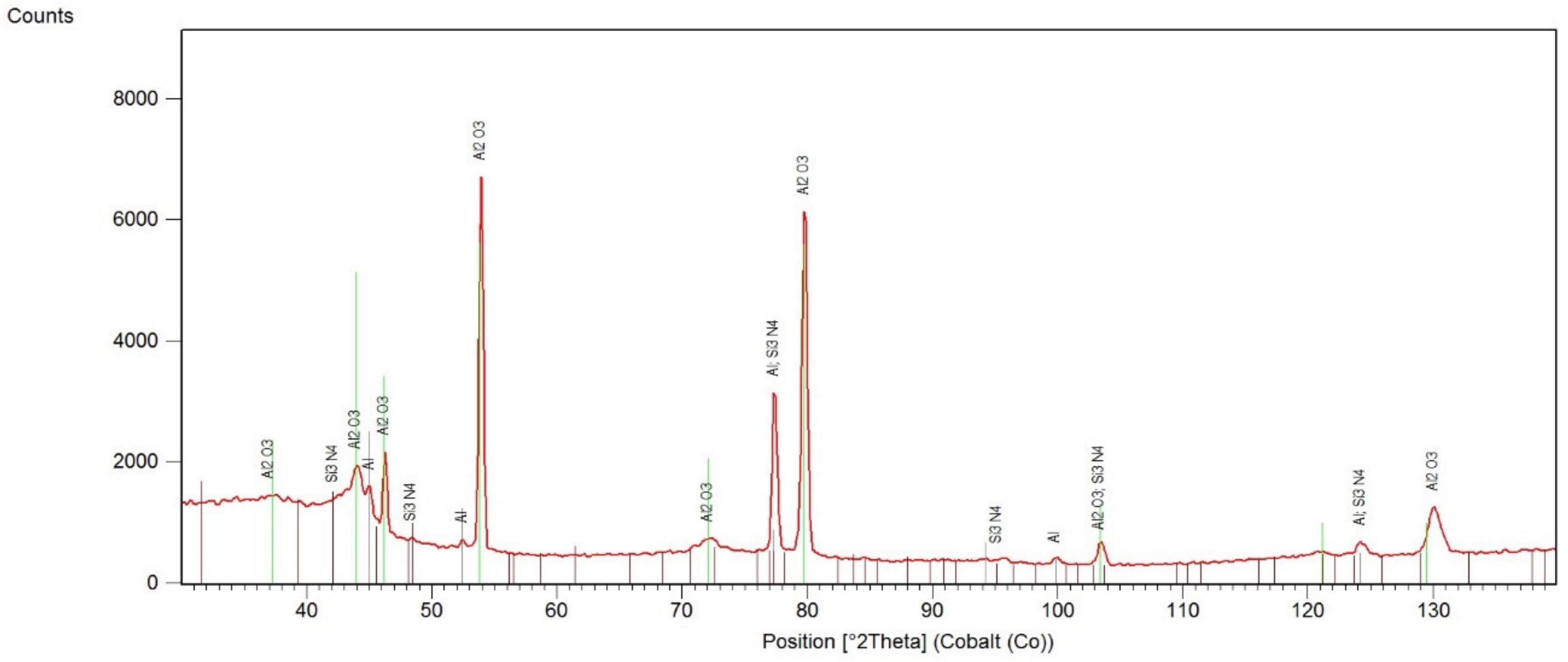
Similar results have been obtained for the layers with Si3N4 nanoparticles embedded (Figure 3). The γ-Al2O3 (ICDD reference: 00-010-0425), Al (ICDD reference: 04-016-4853) and possible traces of Si3N4 (ICDD reference: 04-007-2386) were observed.
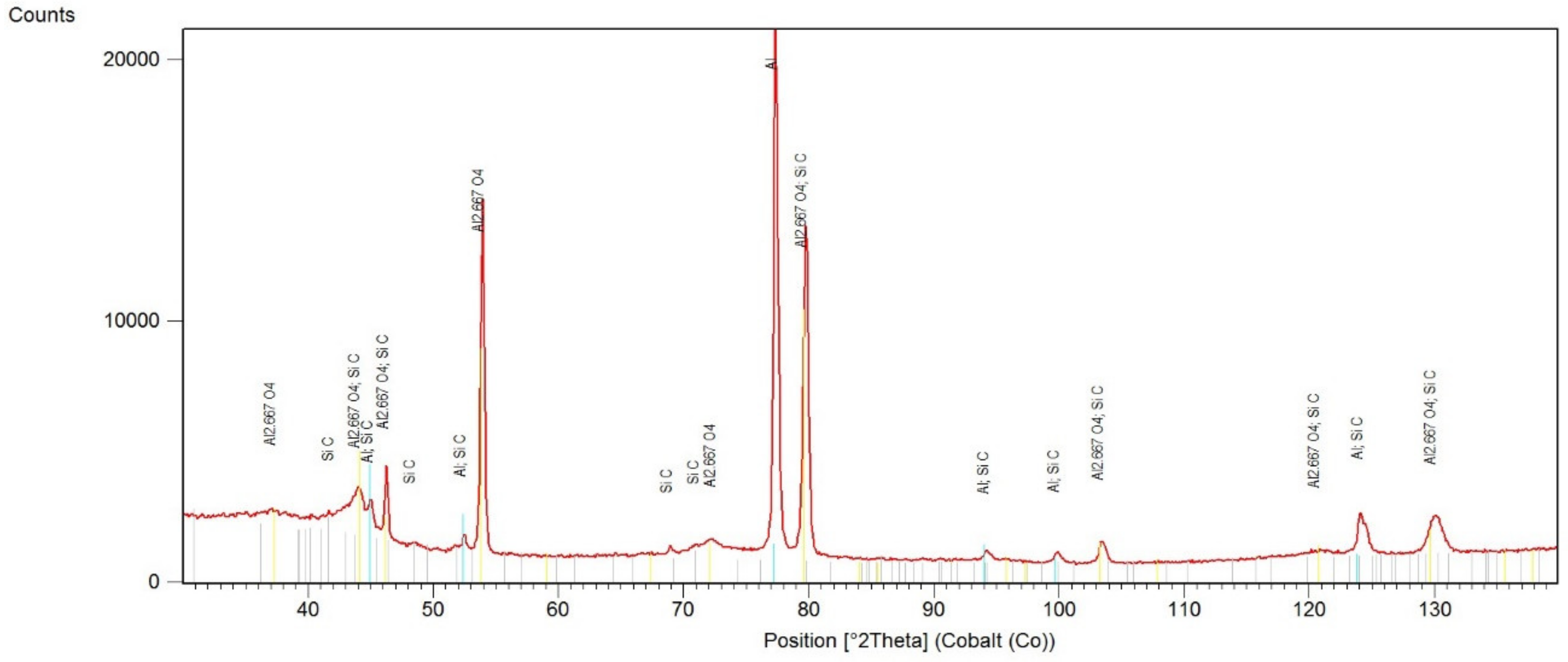
For the layers with SiC nanoparticles embedded (Figure 4), the XRD diffraction patterns revealed presence of different phases, compared to the previous ones.
The SiC phase is observed, but instead of γ-Al2O3 phase, the η-Al2.667O4 (ICDD reference: 04-007-2615) phase has been identified. This presence of the η-Al2.667O4 phase could be explained by a reduction effect on aluminium oxide by carbon originating from the silicon carbide. This leads to formation of oxygen vacancies on the Al2O3 surface, what further provides a driving force for diffusion and crystal growth of aluminium oxide into the one dimensional structure [22].
Another hypothesis is the incomplete crystallization of alumina or due to unexpected temperature variation during the melting/crystallization of alumina during MAO process [28,29]. This is partially confirmed by the results of Ali et al. [30], who have proved that anodizing aluminium begins at lower temperatures with the formation of the η-Al2.667O4 phase, and at higher temperatures it rebuilds into Al2O3 phase.
3.3. Tribological Properties Results
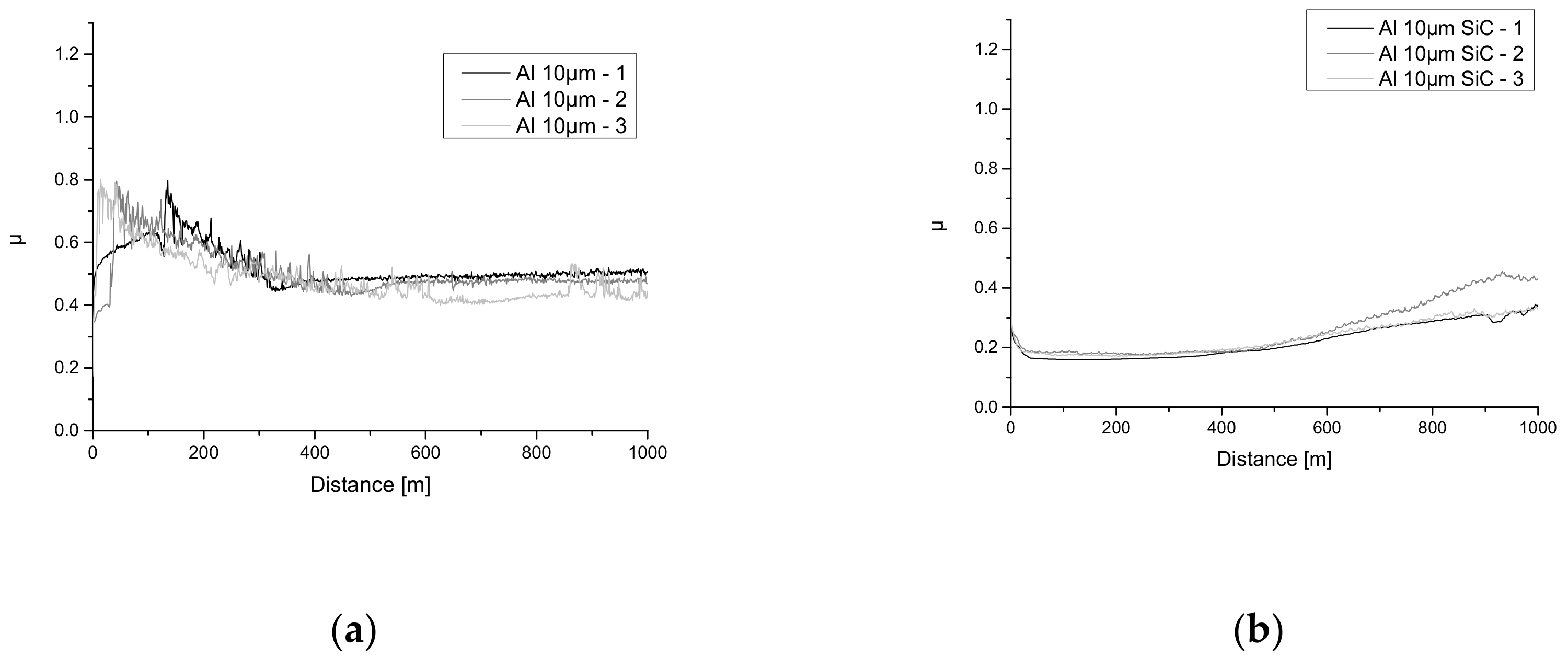
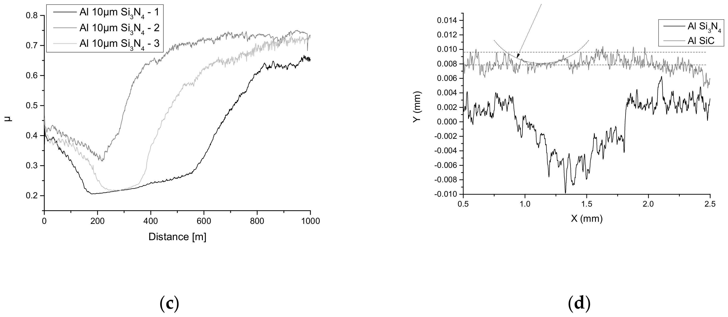
For Al alloy with Al2O3 layer without any additives the friction couple against ZrO2 mean values of the coefficient of friction (COF) are in a range of 0.48 ÷ 0.52. Similar values of the coefficient of friction (–0.4) at room temperature in a friction couple with zirconia were observed in the case of a pure hardened layer on aluminium alloy produced by the micro-arc oxidation (MAO) method [31]. It is interesting that in the friction couple with Si3N4 the hardened layer produced by the MAO method (the same method as described in this paper) has a very high friction coefficient of ~0.8 [32]. COF values of the Al alloy with Al2O3 layer recorded against ZrO2 counterbody became greater when the Si3N4 particles were embedded in the hardened layer. One can notice that in the first ~200 m of Al2O3 + Si3N4–ZrO2 tribological test run the friction coefficient value decreases, and then continuously increases to the highest COF value (>0.6). The authors associate this to effect that the hardened Al2O3 with Si3N4 particles has been worn out and there was a consistent friction between pure Al alloy and ZrO2 counterbody. Torn out Si3N4 particles from the hardened layer and cracked fragments of the Al2O3 layer intensify the friction forces and change the nature of work in a friction contact to more abrasive-like.
As a difference, the hardened Al alloy with Al2O3 layer with embedded SiC particles exhibited the lowest COF value (0.2 ÷ 0.4). Admixture of both Si3N4 and SiC particles was expected to increase the tribological properties of Al2O3 layer. It was proved for SiC nanoparticles (COF in the range 0.2–0.4, a wear rate comparable to non-modified Al2O3) but Si3N4 caused their deterioration. The authors suspect the Si3N4 particles reduce the cohesion of the layer, therefore reducing fatigue resistance which in turn intensifies wear. Similar values of wear can be found in the literature, where a pure hardened layer produced by the MAO method was investigated in a friction couple against Si3N4 [32].
Introducing SiC particles into matrix of the η-Al2.667O4 layer (detected in X-ray analysis) leads to the reduction of COF to the value of 0.24 with preserved very high resistance (172–176) against wear (~10−15 m3⋅N−1⋅m−1). and this value is typical also for pure hardened layers produced by other methods like MAO [31].
Examples of COF values of the hardened Al alloys with Al203 layer with different additives as a function of the friction path at different pin-on-disc test conditions are shown in Figure 5, while the cumulated results of the mean COF values, the wear rates and the test conditions are collected in Table 3. Examples of wear track profiles for different Al2O3 layers after the tribological tests are shown in Figure 5. Considering that the wear was very low (for pure Al2O3 layer and layer embedded with SiC nanoparticles), it was possible to determine the order of magnitude of the kv coefficient, which is sufficient for comparing the obtained results with others.
After performing the tribological tests, microscopic tests were carried out using SEM (S-3000 microscope, Hitachi Ltd., Tokio, Japan) in the BSE mode and EDS analysis (Noran’ Vantage app., NORAN Instruments, Inc., Middleton, WI, USA), which was used to analyse the elemental distribution map in the area of wear. It is shown on Figure 6 and Figure 7.
Performed studies have shown that in both cases we are dealing with an even distribution of elements in the hardened layers, the exception being silicon, for which a greater concentration can be seen on the surface of the produced layers, which is the result of using Na2SiO3 + KOH solution, which remains porous during production of the layer in the final anodizing step.
4. Conclusions
The results of the studies presented in this work strongly indicate that the admixture of different particles (SiC or Si3N4) into the matrix of a Al2O3 hardened layer can influence the tribological properties of the resulting hardened Al alloy. Si3N4 particles embedded in the Al2O3 layer caused a deterioration of the tribological properties of that layer in the friction couple against ZrO2 counterbody—strongly reducing the cohesion of the layer and consequently reducing the resistance against fatigue and wear, intensifying the friction forces and changing the nature of wear in the friction contact area to more abrasive-like.
Introducing SiC particles into anodizing layer resulted instead in formation of a γ-Al2O3 phase, and the η-Al2.667O4 phase has also been identified. Presence of the η-Al2.667O4 phase could be explained by the incomplete crystallization of alumina or due to unexpected temperature variations during the melting/crystallization of alumina during the MAO process [28,30].
It seems that SiC particles present in the anodized layer after the MAO process cause the η-Al2.667O4 phase to stabilize, which means that it does not convert into γ-Al2O3 during the subsequent anodizing stage (increasing temperature in the MAO process), as is the case with clean anodized layers as well as layers with embedded Si3N4 particles. This, in turn, forms a η-Al2.667O4 phase, which is characterized by a cubic lattice, while the of γ-Al2O3 phase has a rhombohedral one [33], directly affecting the nature and intensity of wear during the tribological tests and causing an improvement of the tribological properties of the layer and reducing the COF values to the range 0.2 ÷ 0.26 with preserved very high resistance against wear (~10−15 m3⋅N−1⋅m−1).
Author Contributions
Conceptualization, R.A.; methodology, R.A., M.M., B.J., Ł.K.; validation, R.A., Ł.K. and M.M.; formal analysis, R.A., B.J.; investigation, R.A., M.M., B.J. and Ł.K.; resources, J.S.; writing—original draft preparation, R.A.; writing—review and editing, R.A.; visualization, R.A., B.J., M.M.; project administration, R.A. All authors have read and agreed to the published version of the manuscript.
Funding
This research received no external funding
Conflicts of Interest
The authors declare no conflict of interest.
References
- Davis, J.R.; Associates, J.R.D.; Committee, A.S.M.I.H. Aluminum and Aluminum Alloys; ASM specialty handbook; ASM International: Cleveland, OH, USA, 1993; ISBN 9780871704962. [Google Scholar]
- Ch, S.R.; Raja, A.; Nadig, P.; Jayaganthan, R.; Vasa, N.J. Influence of working environment and built orientation on the tensile properties of selective laser melted AlSi10Mg alloy. Mater. Sci. Eng. A 2019. [Google Scholar] [CrossRef]
- Zhang, L.; Zhang, S.; Zhu, H.; Wang, G.; Zeng, X. Investigation on the angular accuracy of selective laser melting. Int. J. Adv. Manuf. Technol. 2019. [Google Scholar] [CrossRef]
- Mueller, M.; Riede, M.; Eberle, S.; Reutlinger, A.; Brandão, A.D.; Pambaguian, L.; Seidel, A.; López, E.; Brueckner, F.; Beyer, E.; et al. Microstructural, mechanical, and thermo-physical characterization of hypereutectic AlSi40 fabricated by selective laser melting. J. Laser Appl. 2019. [Google Scholar] [CrossRef]
- Rao, H.; Giet, S.; Yang, K.; Wu, X.; Davies, C.H.J. The influence of processing parameters on aluminium alloy A357 manufactured by Selective Laser Melting. Mater. Des. 2016. [Google Scholar] [CrossRef]
- Montoya, Z.R.D.; Vera, L.E.; Pineda, T.Y.; Cedeño, M.L. Effect of the layer of anodized 7075-T6 aluminium corrosion properties. J. Phys. Conf. Ser. 2017, 786, 12032. [Google Scholar] [CrossRef]
- Zhou, L.; Yu, M.; Liu, B.; Zhang, Z.; Liu, S.; Song, X.; Zhao, H. Microstructure and mechanical properties of Al/steel dissimilar welds fabricated by friction surfacing assisted friction stir lap welding. J. Mater. Res. Technol. 2020, 9, 212–221. [Google Scholar] [CrossRef]
- Zhang, C.Q.; Liu, W. Abnormal effect of temperature on intermetallic compound layer growth at aluminum-titanium interface: The role of grain boundary diffusion. Mater. Lett. 2019, 254, 1–4. [Google Scholar] [CrossRef]
- Pietrzyk, B.; Miszczak, S.; Szymanowski, H.; Sobczyk-Guzenda, A.; Gawronski, Z. Plasma enhanced aerosol–gel method: A new way of preparing ceramic coatings. J. Sol Gel Sci. Technol. 2013, 68, 455–463. [Google Scholar] [CrossRef] [Green Version]
- Pietrzyk, B.; Miszczak, S.; Kaczmarek, Ł.; Klich, M. Low friction nanocomposite aluminum oxide/MoS2 coatings prepared by sol-gel method. Ceram. Int. 2018, 44, 8534–8539. [Google Scholar] [CrossRef]
- Curran, J.A.; Clyne, T.W. Thermo-physical properties of plasma electrolytic oxide coatings on aluminium. Surf. Coat. Technol. 2005, 199, 168–176. [Google Scholar] [CrossRef]
- Ibrahim, H.; Esfahani, S.N.; Poorganji, B.; Dean, D.; Elahinia, M. Resorbable bone fixation alloys, forming, and post-fabrication treatments. Mater. Sci. Eng. C 2017, 70, 870–888. [Google Scholar] [CrossRef] [PubMed] [Green Version]
- Dunleavy, C.S.; Golosnoy, I.O.; Curran, J.A.; Clyne, T.W. Characterisation of discharge events during plasma electrolytic oxidation. Surf. Coat. Technol. 2009, 203, 3410–3419. [Google Scholar] [CrossRef] [Green Version]
- Snizhko, L.O.; Yerokhin, A.L.; Pilkington, A.; Gurevina, N.L.; Misnyankin, D.O.; Leyland, A.; Matthews, A. Anodic processes in plasma electrolytic oxidation of aluminium in alkaline solutions. Electrochim. Acta 2004. [Google Scholar] [CrossRef]
- Moon, S.; Jeong, Y. Generation mechanism of microdischarges during plasma electrolytic oxidation of Al in aqueous solutions. Corros. Sci. 2009. [Google Scholar] [CrossRef]
- Matijošius, T.; Ručinskienė, A.; Selskis, A.; Stalnionis, G.; Leinartas, K.; Asadauskas, S.J. Friction reduction by nanothin titanium layers on anodized alumina. Surf. Coat. Technol. 2016, 307, 610–621. [Google Scholar] [CrossRef]
- Canyook, R.; Seubsom, P.; Sang-ngean, J.; Trirujirapapong, T.; Taweesup, K. Influences of sealing solutions on anodized layer properties of 7075 aluminium alloy. Mater. Today Proc. 2018, 5, 9483–9488. [Google Scholar] [CrossRef]
- Jabbari, R.; Mirjani, M.; Rezagholi, H. Study on mechanical properties of anodised film containing nano-diamond particles. Trans. IMF 2016, 94, 166–170. [Google Scholar] [CrossRef]
- MatWeb Material Property Data Aluminum 2017A Composition Spec. Available online: http://www.matweb.com/search/DataSheet.aspx?MatGUID=236edd2c6b2e4b02a8b902797094ef7f&ckck=1 (accessed on 18 March 2020).
- Aircraft Materials UK Aluminium Alloy 2017A Technical Data Sheet. Available online: https://www.aircraftmaterials.com/data/aluminium/2017a.html (accessed on 18 March 2020).
- Lu, J.; Wei, G.; Yu, Y.; Guo, C.; Jiang, L. Aluminum alloy AA2024 anodized from the mixed acid system with enhanced mechanical properties. Surf. Interfaces 2018. [Google Scholar] [CrossRef]
- Kamali, A.R.; Feighan, J.; Fray, D.J. Towards large scale preparation of graphene in molten salts and its use in the fabrication of highly toughened alumina ceramics. Faraday Discuss. 2016. [Google Scholar] [CrossRef]
- Guezmil, M.; Bensalah, W.; Khalladi, A.; Elleuch, K.; Depetris-Wery, M.; Ayedi, H. Friction coefficient and microhardness of anodized aluminum alloys under different elaboration conditions. Trans. Nonferrous Met. Soc. China 2015, 25, 1950–1960. [Google Scholar] [CrossRef]
- Gudla, V.C.; Bordo, K.; Jensen, F.; Canulescu, S.; Yuksel, S.; Simar, A.; Ambat, R. High frequency anodising of aluminium–TiO2 surface composites: Anodising behaviour and optical appearance. Surf. Coatings Technol. 2015, 277, 67–73. [Google Scholar] [CrossRef] [Green Version]
- Gudla, V.C.; Jensen, F.; Bordo, K.; Simar, A.; Ambat, R. Effect of high frequency pulsing on the interfacial structure of anodized aluminium-TiO2. J. Electrochem. Soc. 2015, 162, C303–C310. [Google Scholar] [CrossRef]
- Pharr, G.M.; Oliver, W.C. On the generality of the relationship among contact stiffness, contact area and elastic modulus during indentation. J. Mater. Res. 1992, 7, 613–617. [Google Scholar] [CrossRef]
- Archard, J.F. Contact and rubbing of flat surfaces. J. Appl. Phys. 1953, 24, 981–988. [Google Scholar] [CrossRef]
- Durães, L.; Costa, B.F.O.; Santos, R.; Correia, A.; Campos, J.; Portugal, A. Fe2O3/aluminum thermite reaction intermediate and final products characterization. Mater. Sci. Eng. A 2007. [Google Scholar] [CrossRef] [Green Version]
- Rabbani, F.A.; Malaibari, Z.O.; Atieh, M.A.; Jamie, A. Catalytic synthesis of substrate-free, aligned and tailored high aspect ratio multiwall carbon nanotubes in an ultrasonic atomization head CVD reactor. J. Nanomater. 2016. [Google Scholar] [CrossRef]
- Ali, M.A.; Hamiduddin; Zaigham, M.; Ikram, M.; Ranjan, R. Pharmaceutico-analytical Study of Kushtae Shangarf Prepared with Jozbua (Myristica fragrans Houtt.) and Phitkari (Alum). J. Pharm. Bioallied Sci. 2018, 10, 144. [Google Scholar]
- Yang, X.; Chen, L.; Jin, X.; Du, J.; Xue, W. Influence of temperature on tribological properties of microarc oxidation coating on 7075 aluminium alloy at 25 °C –300 °C. Ceram. Int. 2019, 45, 12312–12318. [Google Scholar] [CrossRef]
- Malayoglu, U.; Tekin, K.C.; Malayoglu, U.; Shrestha, S. An investigation into the mechanical and tribological properties of plasma electrolytic oxidation and hard-anodized coatings on 6082 aluminum alloy. Mater. Sci. Eng. A 2011, 528, 7451–7460. [Google Scholar] [CrossRef]
- Pogrebnjak, A.D.; Novosad, V. Advances in Thin Films, Nanostructured Materials, and Coatings; Springer: Berlin/Heidelberg, Germany, 2019. [Google Scholar]
Figure 1.
Hardness profile of 10µm thick anodized layer measured at normal load of 3 mN.

Figure 2.
XRD pattern of anodized layer.

Figure 3.
XRD pattern of the anodized layer with Si3N4 particles.

Figure 4.
XRD pattern of the anodized layer with SiC particles.

Figure 5.
Friction coefficient evolution for pin-on-disc test against ZrO2 bearing ball for Al alloy with: (a) 10 µm thick Al2O3 layer, (b) 10 µm thick η-Al2.667O4 layer with embedded SiC particles and (c) 10 µm thick Al2O3 layer with embedded Si3N4 particles. (d) Example of wear track profiles after tribological tests of Al alloys with hardened layers with embedded different particles. On the upper profile (Al2O3 + Si3N4 layer) the worn area and wear profile have been marked.


Figure 6.
Distribution map in the area of wear of anodized layer with Si3N4 nanoparticles.

Figure 7.
Distribution map in the area of wear of anodized layer with SiC nanoparticles.


| Si | Fe | Cu | Mn | Mg | Cr | Zn | Ti | Other | Al | |
|---|---|---|---|---|---|---|---|---|---|---|
| wt.(%) | 0.2–0.8 | 0.7 max | 3.5–4.5 | 0.4–1 | 0.4–0.8 | 0.1 max | 0.25 max | 0.15 max | 0.15 max | balance |
| Tensile strength | Yield strength | Young modulus | Hardness | Elongation | ||||||
| 379 MPa | 221 MPa | 72.4 GPa | 45 HB | 22% | ||||||
Table 2.
Anodizing parameters.
| Current Density(A/dcm2) | Voltage (V) | Inductance (H) | Electrolyte | Temperature (°C) |
|---|---|---|---|---|
| 6 | 500 | 1000 | Na2SiO3 + KOH | <10 |
Table 3.
Cumulative results of tribological studies.
| Specimen | Load (N)) | Subs. Temp. (°C) | Rel. Hum. RH (%) | Friction Radius (mm) | Friction Path(m) | Mean Value of Coef. Friction with Calculated SD | Wear Rate with Calculated SD (m3·N−1·m−1 × 10⁻¹⁵) |
|---|---|---|---|---|---|---|---|
| Al 10 µm–1 | 5 | 24 | 64 | 10 | 1000 | 0.48 ± 0.08 | 2 ± 0.6 |
| Al 10 µm–2 | 5 | 24 | 64 | 0.51 ± 0.08 | 2.5 ± 0.3 | ||
| Al 10 µm–3 | 10 | 27.7 | 63 | 0.52 ± 0.06 | 4 ± 2 | ||
| Al 10 µm SiC–1 | 4 | 26 | 49 | 0.22 ± 0.06 | 1.4 ± 0.6 | ||
| Al 10 µm SiC–2 | 5 | 21.7 | 60 | 0.26 ± 0.09 | 1.9 ± 0.1 | ||
| Al 10 µm SiC–3 | 5 | 25.8 | 59.8 | 0.23 ± 0.05 | 2.5 ± 0.9 | ||
| Al 10 µm Si3N4–1 | 4 | 21.5 | 53.4 | 0.4 ± 0.2 | 15 ± 3 | ||
| Al 10 µm Si3N4–2 | 5 | 25.5 | 50.8 | 0.6 ± 0.2 | 20 ± 3 | ||
| Al 10 µm Si3N4–3 | 5 | 26.3 | 48 | 0.5 ± 0.2 | 94 ± 4 |
© 2020 by the authors. Licensee MDPI, Basel, Switzerland. This article is an open access article distributed under the terms and conditions of the Creative Commons Attribution (CC BY) license (http://creativecommons.org/licenses/by/4.0/).
Share and Cite
MDPI and ACS Style
Atraszkiewicz, R.; Makówka, M.; Kołodziejczyk, Ł.; Januszewicz, B.; Sucharkiewicz, J. Frictional Behaviour of Composite Anodized Layers on Aluminium Alloys. Materials 2020, 13, 3747. https://doi.org/10.3390/ma13173747
AMA Style
Atraszkiewicz R, Makówka M, Kołodziejczyk Ł, Januszewicz B, Sucharkiewicz J. Frictional Behaviour of Composite Anodized Layers on Aluminium Alloys. Materials. 2020; 13(17):3747. https://doi.org/10.3390/ma13173747
Chicago/Turabian StyleAtraszkiewicz, Radomir, Marcin Makówka, Łukasz Kołodziejczyk, Bartłomiej Januszewicz, and Jan Sucharkiewicz. 2020. "Frictional Behaviour of Composite Anodized Layers on Aluminium Alloys" Materials 13, no. 17: 3747. https://doi.org/10.3390/ma13173747
Note that from the first issue of 2016, this journal uses article numbers instead of page numbers. See further details here.