Additive Manufacturing of Alloy 718 via Electron Beam Melting: Effect of Post-Treatment on the Microstructure and the Mechanical Properties

 ,
,
Abstract
:1. Introduction
2. Materials and Methods
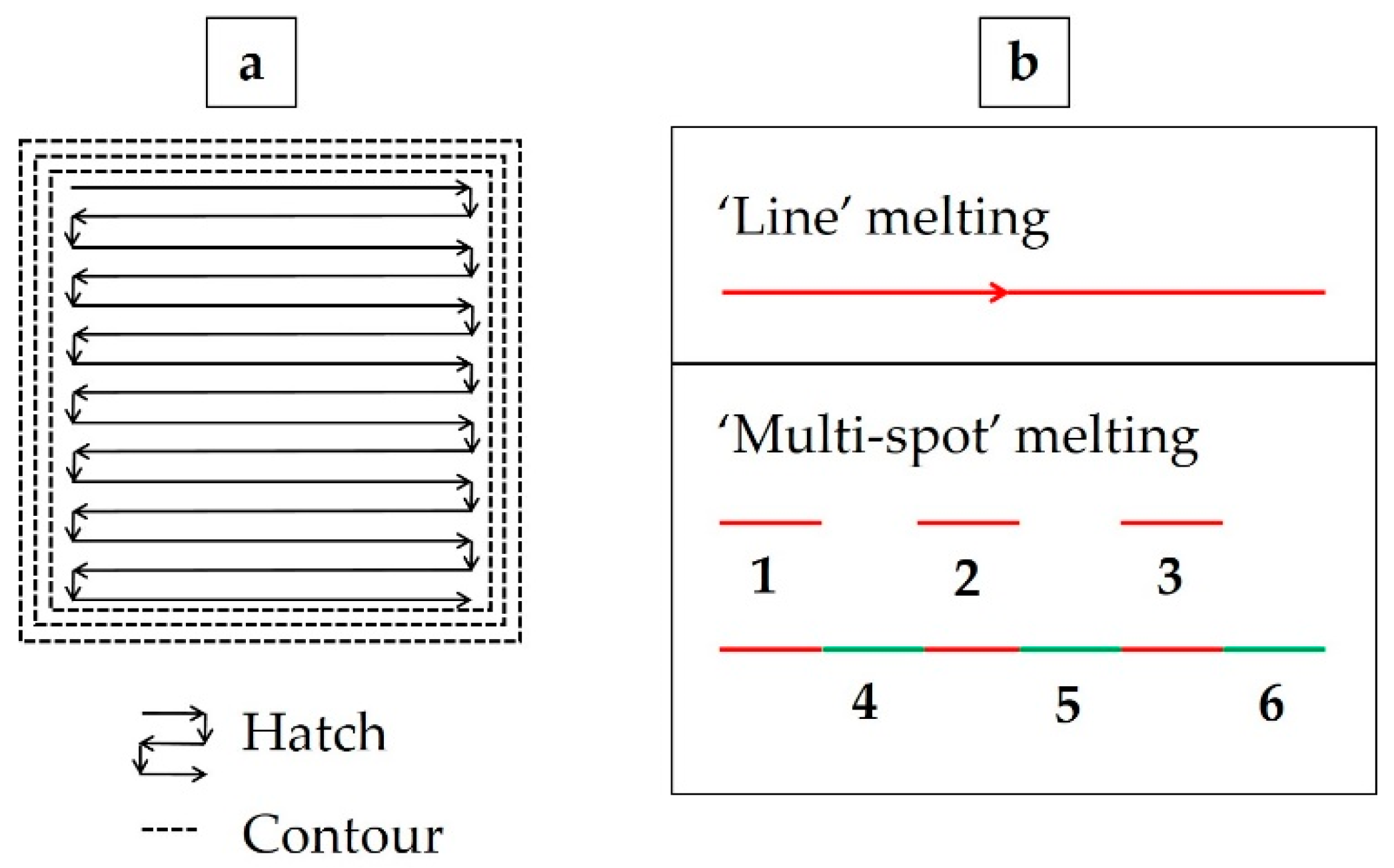
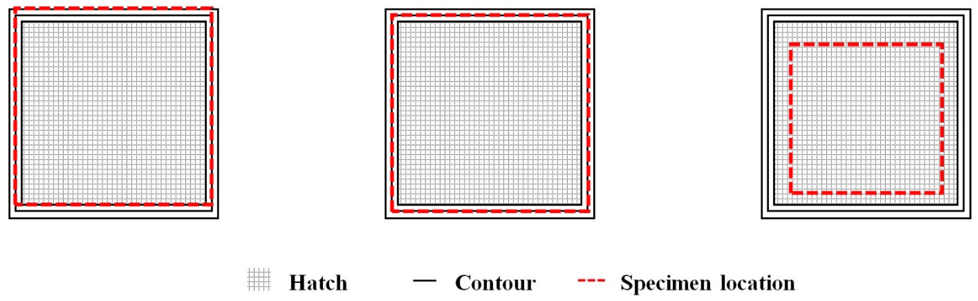
2.1. Specimen Manufacturing
2.2. Metallography
2.3. Thermal Post-Treatment
2.4. Hardness Testing
2.5. Tensile Testing
2.6. Fatigue Testing
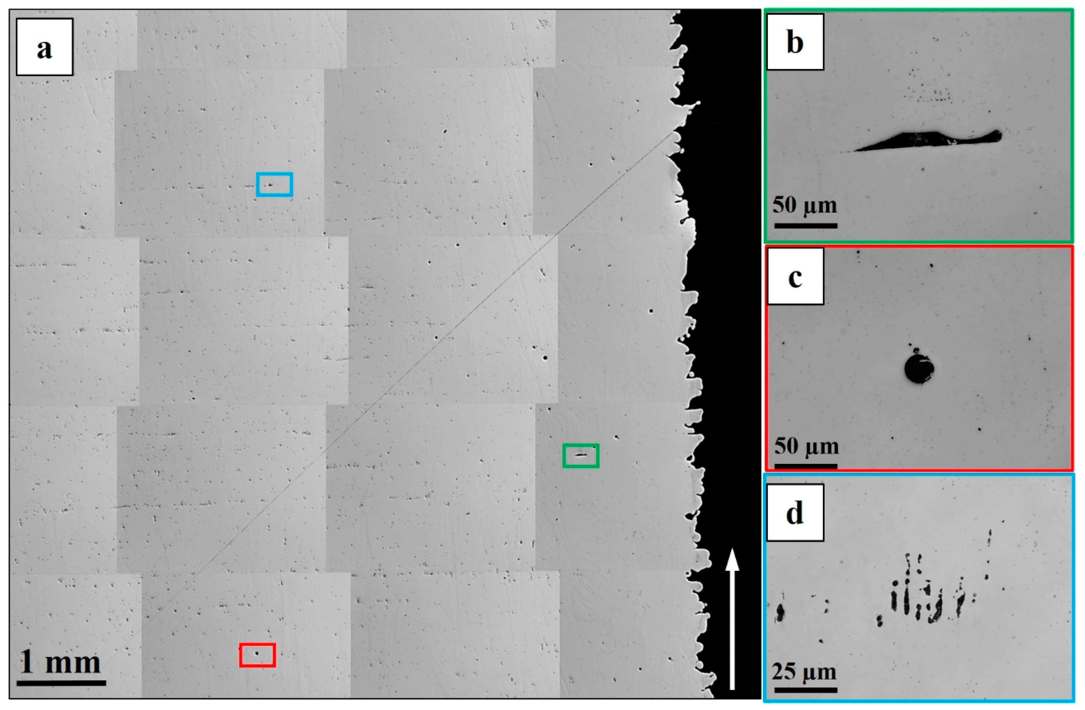
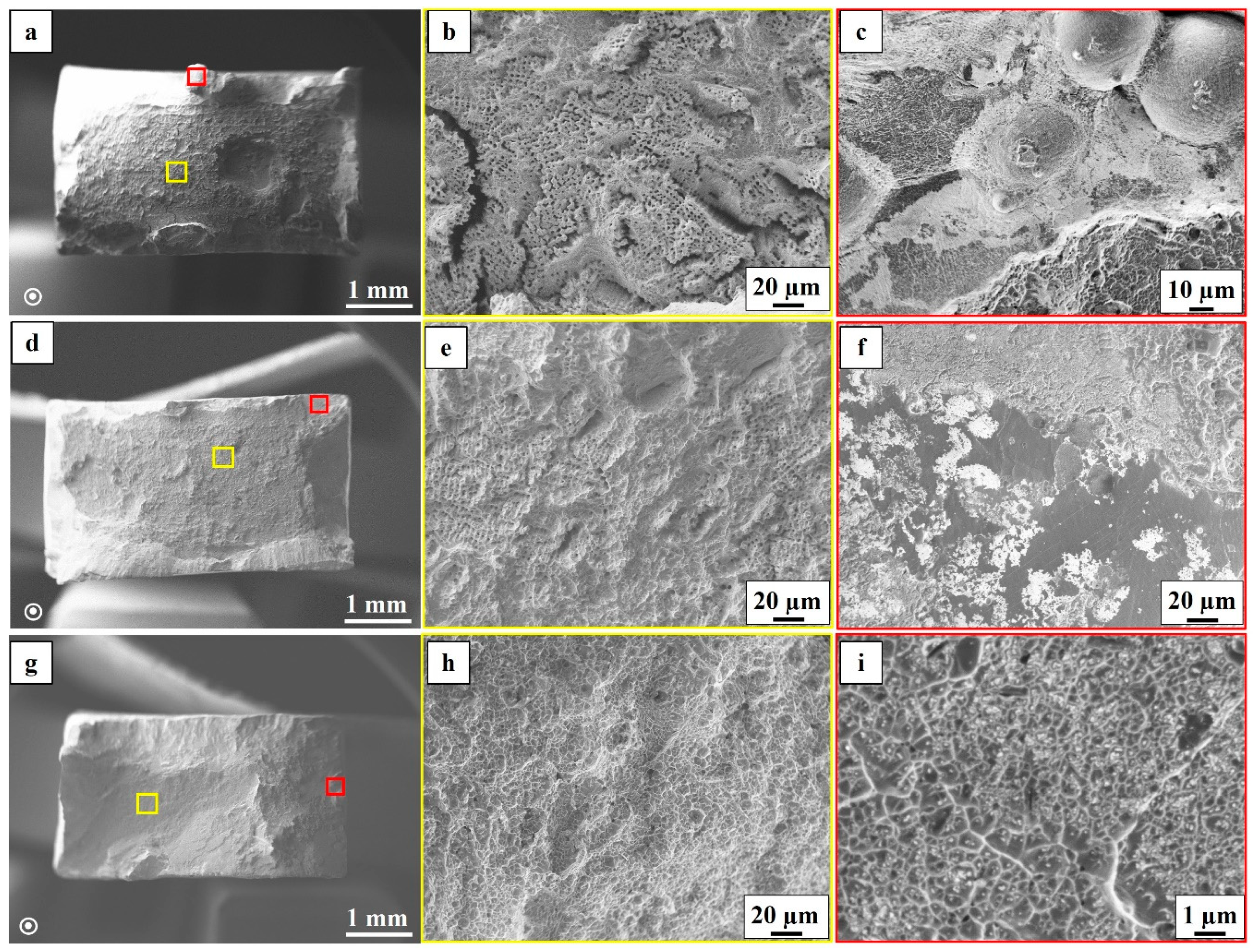
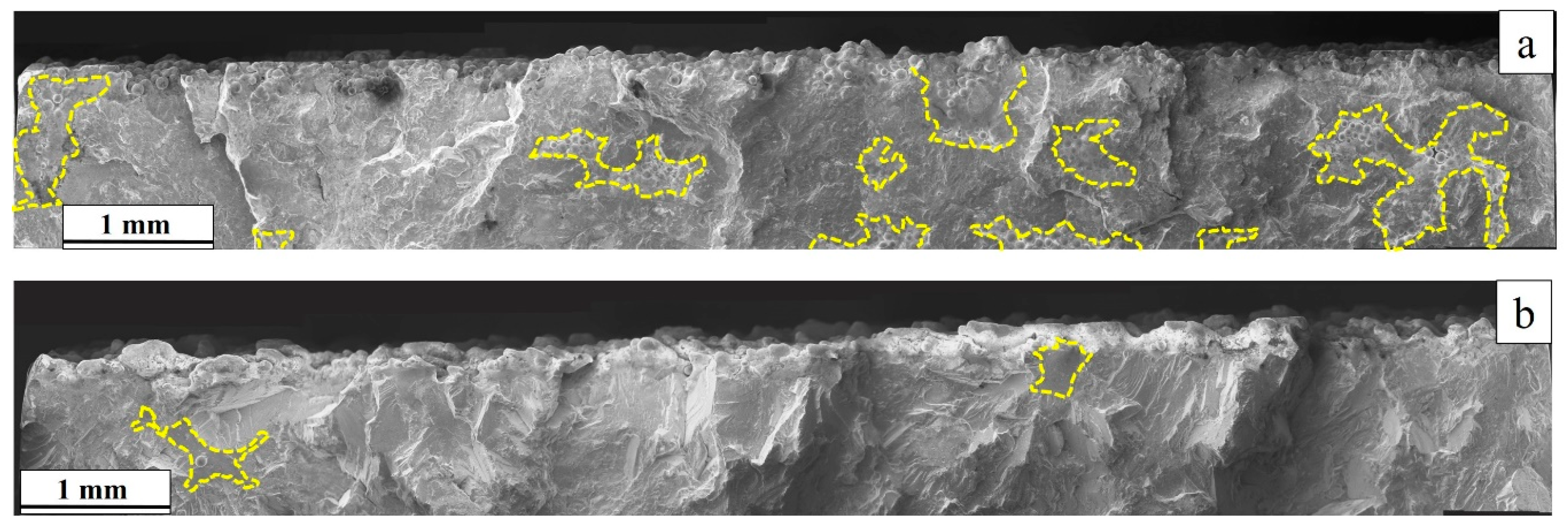
2.7. Fractography
3. Results
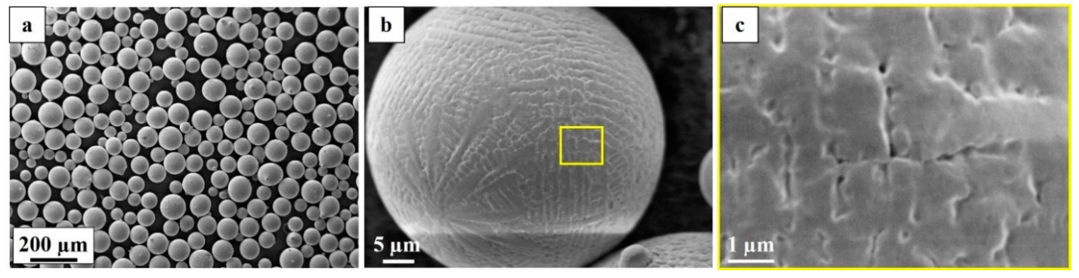
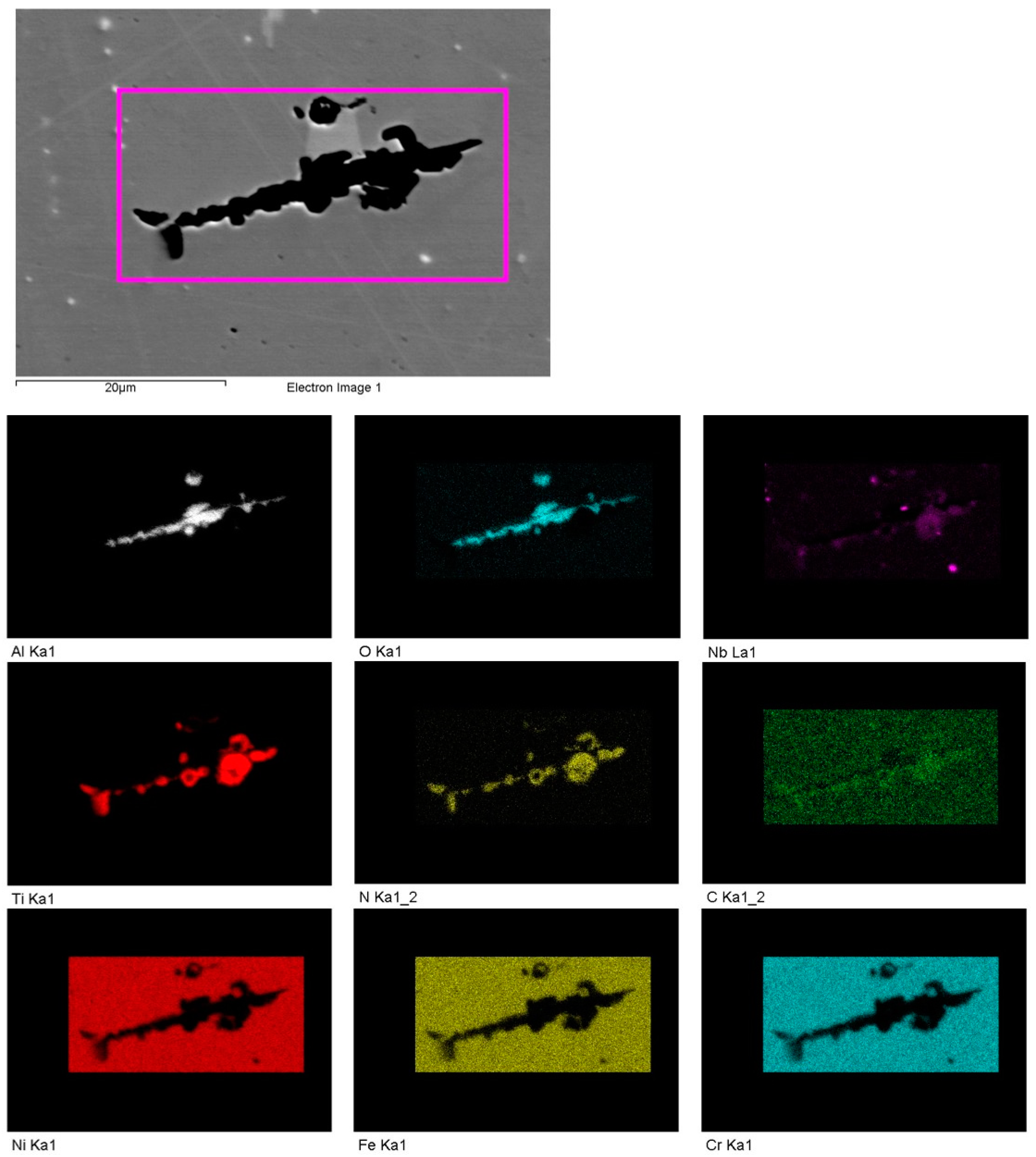
3.1. Powder Characterization
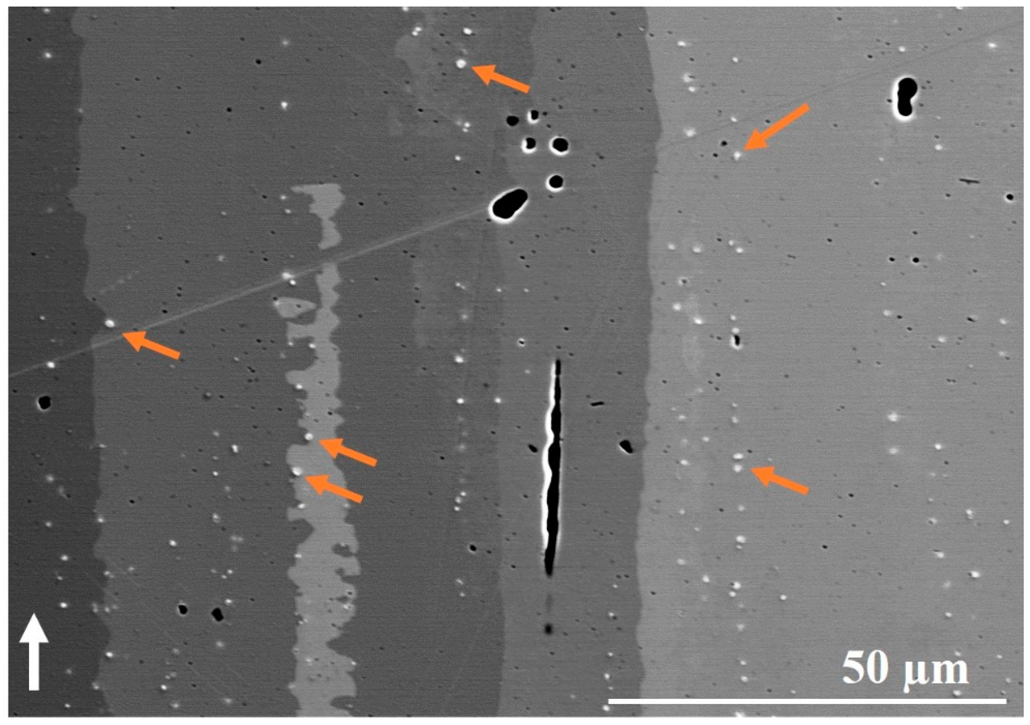
3.2. Microstructure
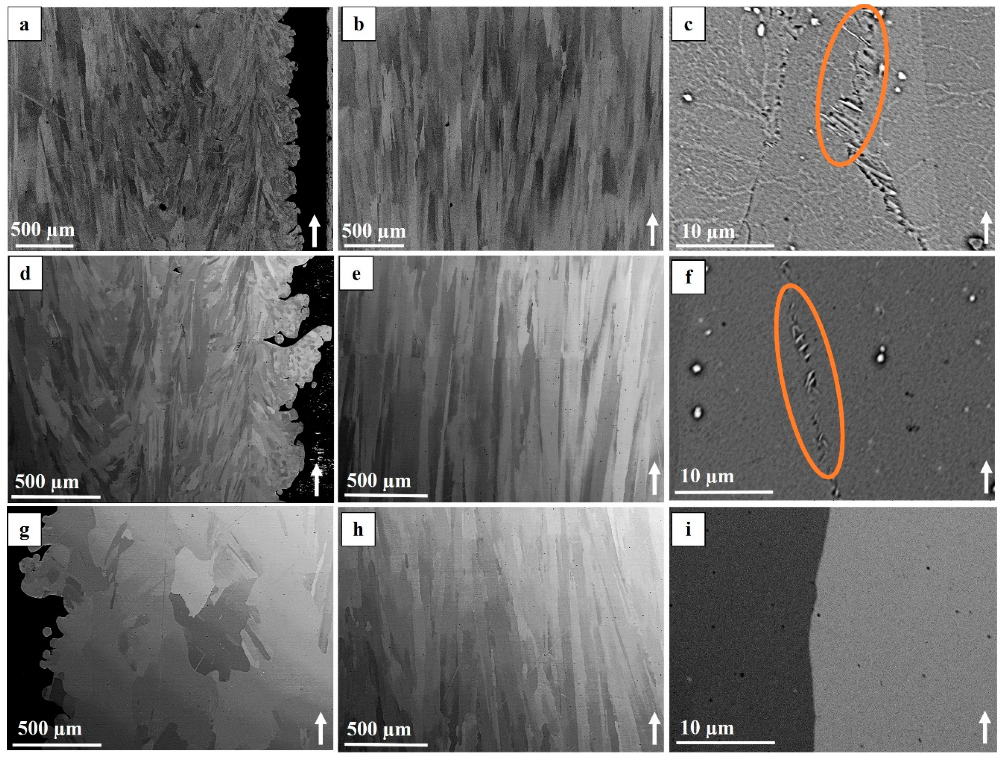
3.2.1. As-built Condition
3.2.2. STA Condition
3.2.3. HIP+STA Condition
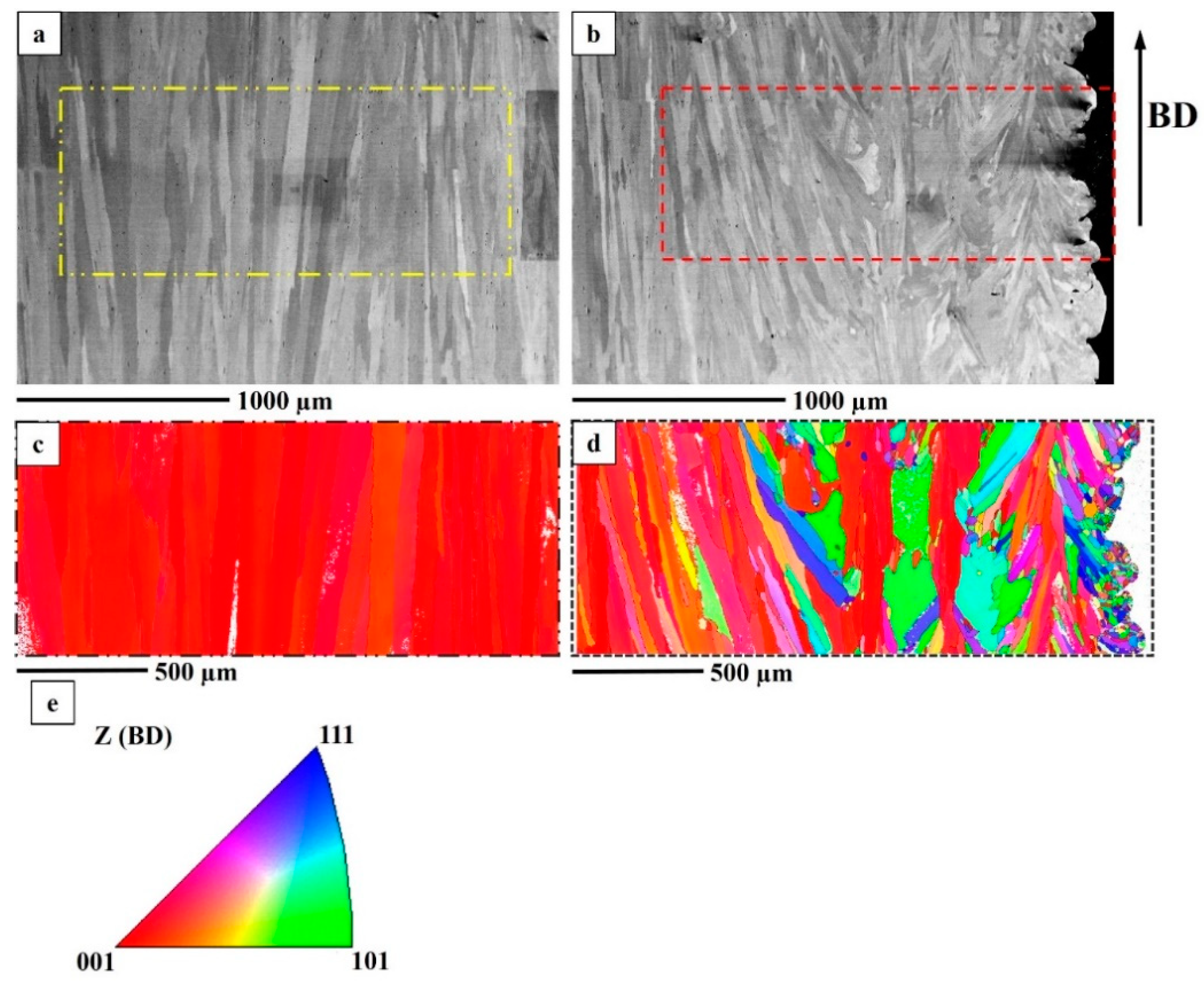
3.2.4. Texture
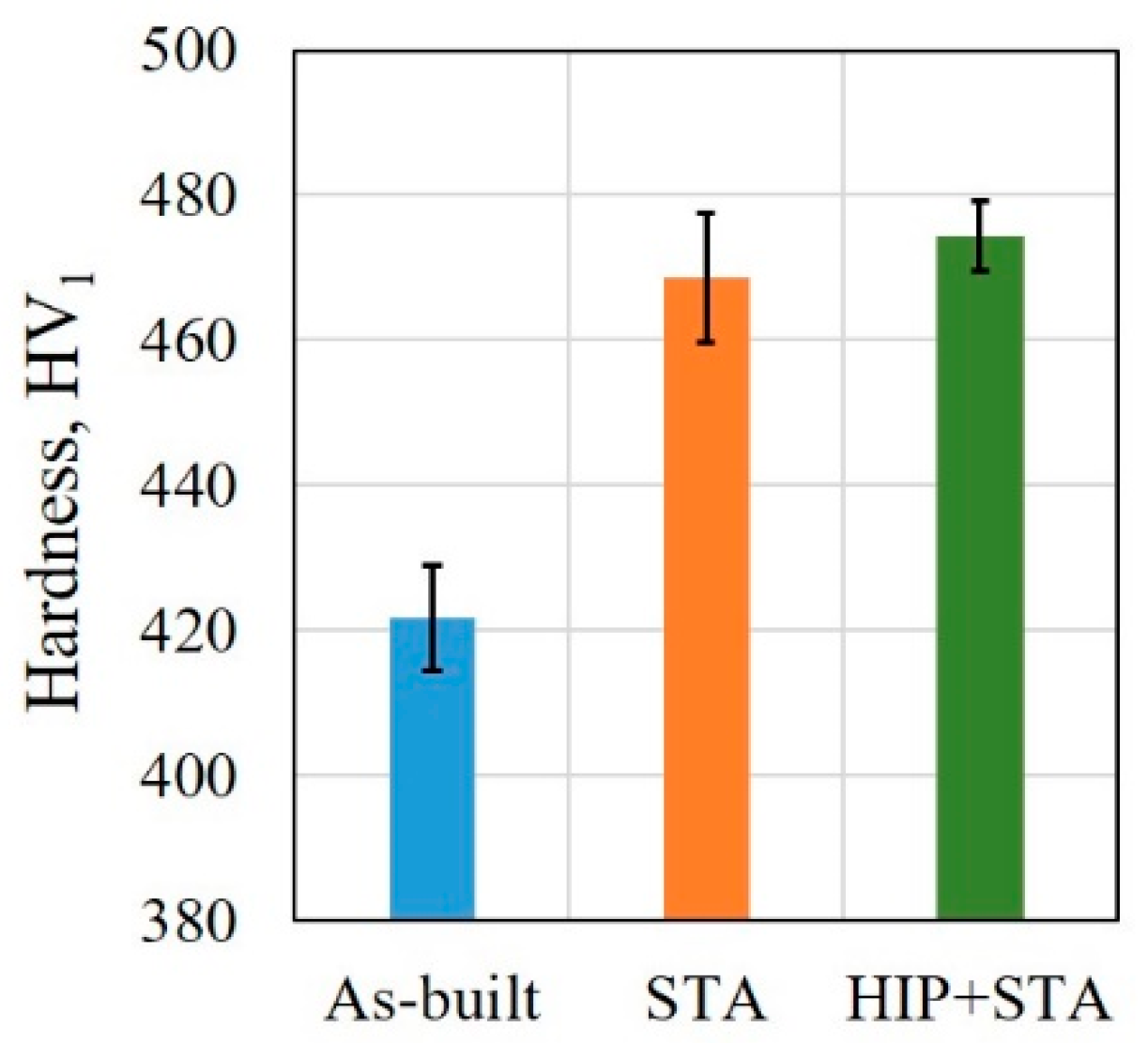
3.3. Hardness
3.4. Tensile Properties
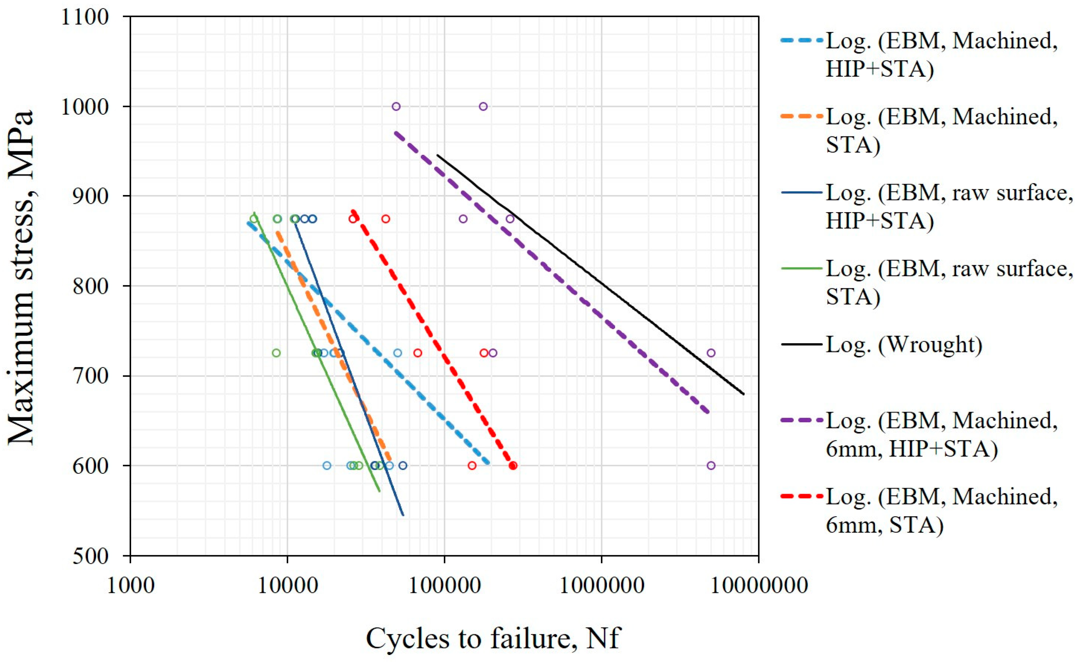
3.5. Fatigue Properties
4. Discussion
4.1. Powder Characteristics
4.2. Microstructure
4.3. Hardness
4.4. Tensile Properties
4.5. Fatigue Properties
5. Conclusions
- In the as-built condition, the needle-like δ phase was present only at certain grain boundaries. In the STA condition, the δ phase precipitates were smaller in size than those observed in the as-built condition. In the HIP+STA condition, the δ phase was not observed at all due to complete dissolution.
- The HIP+STA treatment resulted in grain coarsening in the contour region, while no change in grain size was found after the STA treatment when compared to that of the as-built material.
- The hardness of the as-built material was lower than that of the STA and HIP+STA treated materials. The material in the HIP+STA condition was marginally higher than in the STA condition.
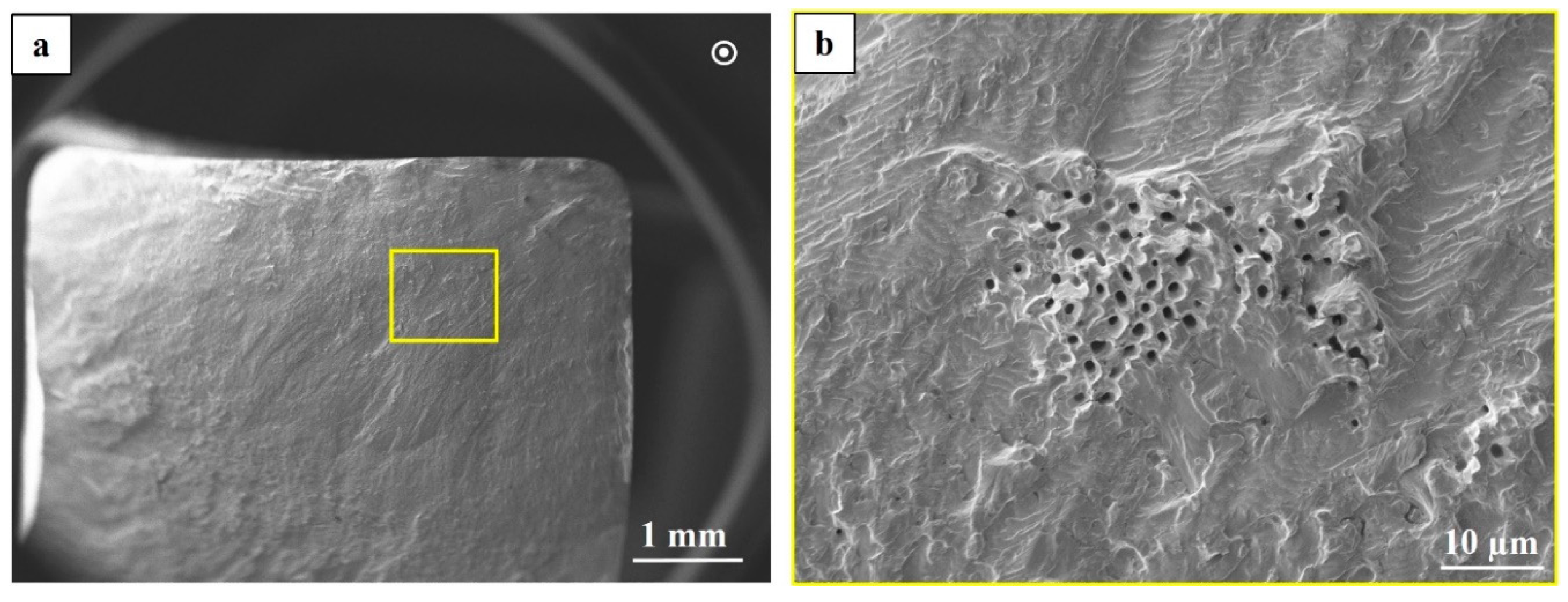
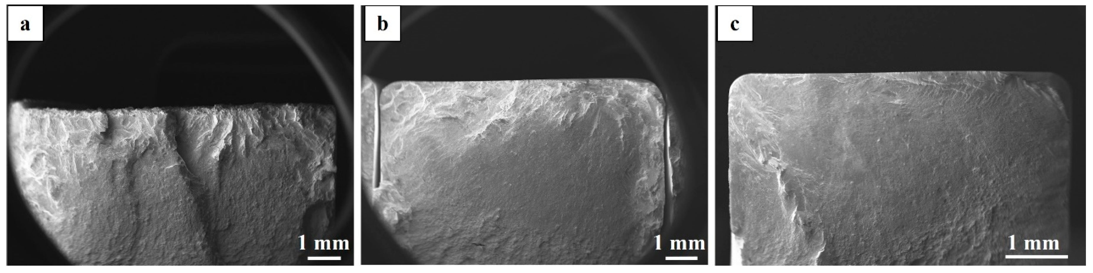
- The post-treatments led to an increase in YS and UTS. HIP+STA led to improved elongation compared to STA due to the closure of defects but YS and UTS were comparable in both the conditions. Fracture analysis of HIP+STA specimens showed partial healing of LoF defects.
- Fatigue strength improved with the HIP+STA treatment. The highest fatigue strength was achieved when the contours were completely removed prior to testing.
- The faceted appearance of fatigue fracture surfaces was found to be affected by both the grain size and the texture.
Author Contributions
Funding
Acknowledgments
Conflicts of Interest
Data Availability
References
- Gong, X.; Anderson, T.; Chou, K. Review on powder-based electron beam additive manufacturing technology. Manuf. Rev. 2014, 1, 2. [Google Scholar] [CrossRef] [Green Version]
- Körner, C. Additive manufacturing of metallic components by selective electron beam melting—A review. Int. Mater. Rev. 2016, 61, 361–377. [Google Scholar] [CrossRef]
- Raghavan, N.; Dehoff, R.; Pannala, S.; Simunovic, S.; Kirka, M.; Turner, J.; Carlson, N.; Babu, S.S. Numerical modeling of heat-transfer and the influence of process parameters on tailoring the grain morphology of IN718 in electron beam additive manufacturing. Acta Mater. 2016, 112, 303–314. [Google Scholar] [CrossRef] [Green Version]
- Raghavan, N.; Simunovic, S.; Dehoff, R.; Plotkowski, A.; Turner, J.; Kirka, M.; Babu, S. Localized melt-scan strategy for site specific control of grain size and primary dendrite arm spacing in electron beam additive manufacturing. Acta Mater. 2017, 140, 375–387. [Google Scholar] [CrossRef]
- Sochalski-Kolbus, L.M.; Payzant, E.A.; Cornwell, P.A.; Watkins, T.R.; Babu, S.S.; Dehoff, R.R.; Lorenz, M.; Ovchinnikova, O.; Duty, C. Comparison of Residual Stresses in Inconel 718 Simple Parts Made by Electron Beam Melting and Direct Laser Metal Sintering. Metall. Mater. Trans. A Phys. Metall. Mater. Sci. 2015, 46, 1419–1432. [Google Scholar] [CrossRef]
- Murr, L.E.; Quinones, S.A.; Gaytan, S.M.; Lopez, M.I.; Rodela, A.; Martinez, E.Y.; Hernandez, D.H.; Martinez, E.; Medina, F.; Wicker, R.B. Microstructure and mechanical behavior of Ti-6Al-4V produced by rapid-layer manufacturing, for biomedical applications. J. Mech. Behav. Biomed. Mater. 2009, 2, 20–32. [Google Scholar] [CrossRef] [PubMed]
- Antonysamy, A.A. Microstructure, Texture and Mechanical Property Evolution during Additive Manufacturing of Ti6Al4V Alloy for Aerospace Applications; University of Manchester: Manchester, UK, 2012; 316p. [Google Scholar]
- Strondl, A.; Fischer, R.; Frommeyer, G.; Schneider, A. Investigations of MX and γ′/γ″ precipitates in the nickel-based superalloy 718 produced by electron beam melting. Mater. Sci. Eng. A 2008, 480, 138–147. [Google Scholar] [CrossRef]
- Deng, D.; Moverare, J.; Peng, R.L.; Söderberg, H. Microstructure and anisotropic mechanical properties of EBM manufactured Inconel 718 and effects of post heat treatments. Mater. Sci. Eng. A 2017, 693, 151–163. [Google Scholar] [CrossRef]
- Kirka, M.M.; Unocic, K.A.; Raghavan, N.; Medina, F.; Dehoff, R.R.; Babu, S.S. Microstructure Development in Electron Beam-Melted Inconel 718 and Associated Tensile Properties. JOM 2016, 68, 1012–1020. [Google Scholar] [CrossRef]
- Helmer, H.; Bauereiß, A.; Singer, R.F.F.; Körner, C. Grain structure evolution in Inconel 718 during selective electron beam melting. Mater. Sci. Eng. A 2016, 668, 180–187. [Google Scholar] [CrossRef]
- Dehoff, R.R.; Kirka, M.M.; List, F.A.; Unocic, K.A.; Sames, W.J. Crystallographic texture engineering through novel melt strategies via electron beam melting: Inconel 718. Mater. Sci. Technol. 2015, 31, 939–944. [Google Scholar] [CrossRef]
- Kirka, M.M.; Lee, Y.; Greeley, D.A.; Okello, A.; Goin, M.J.; Pearce, M.T.; Dehoff, R.R. Strategy for Texture Management in Metals Additive Manufacturing. JOM 2017, 69, 523–531. [Google Scholar] [CrossRef] [Green Version]
- Deng, D.; Peng, R.L.; Söderberg, H.; Moverare, J. On the formation of microstructural gradients in a nickel-base superalloy during electron beam melting. Mater. Des. 2018, 160, 251–261. [Google Scholar] [CrossRef]
- Nandwana, P.; Kirka, M.; Okello, A.; Dehoff, R. Electron beam melting of Inconel 718: Effects of processing and post-processing. Mater. Sci. Technol. 2018, 34, 612–619. [Google Scholar] [CrossRef]
- Sames, W.J.; Unocic, K.A.; Dehoff, R.R.; Lolla, T.; Babu, S.S. Thermal effects on microstructural heterogeneity of Inconel 718 materials fabricated by electron beam melting. J. Mater. Res. 2014, 29, 1920–1930. [Google Scholar] [CrossRef]
- Strondl, A.; Palm, M.; Gnauk, J.; Frommeyer, G. Microstructure and mechanical properties of nickel based superalloy IN718 produced by rapid prototyping with electron beam melting (EBM). Mater. Sci. Technol. 2011, 27, 876–883. [Google Scholar] [CrossRef]
- Tammas-Williams, S.; Zhao, H.; Léonard, F.; Derguti, F.; Todd, I.; Prangnell, P.B. XCT analysis of the influence of melt strategies on defect population in Ti-6Al-4V components manufactured by Selective Electron Beam Melting. Mater. Charact. 2015, 102, 47–61. [Google Scholar] [CrossRef]
- Balachandramurthi, A.R.; Moverare, J.; Dixit, N.; Pederson, R. Influence of defects and as-built surface roughness on fatigue properties of additively manufactured Alloy 718. Mater. Sci. Eng. A 2018, 735, 463–474. [Google Scholar] [CrossRef]
- El-Bagoury, N.; Matsuba, T.; Yamamoto, K.; Miyahara, H.; Ogi, K. Influence of Heat Treatment on the Distribution of Ni2Nb and Microsegregation in Cast Inconel 718 Alloy. Mater. Trans. 2005, 46, 2478–2483. [Google Scholar] [CrossRef]
- Rao, G.A.; Srinivas, M.; Sarma, D.S. Influence of modified processing on structure and properties of hot isostatically pressed superalloy Inconel 718. Mater. Sci. Eng. A 2006, 418, 282–291. [Google Scholar] [CrossRef]
- Slama, C.; Abdellaoui, M. Structural characterization of the aged Inconel 718. J. Alloys Compd. 2000, 306, 277–284. [Google Scholar] [CrossRef]
- Schneider, J.; Lund, B.; Fullen, M. Effect of heat treatment variations on the mechanical properties of Inconel 718 selective laser melted specimens. Addit. Manuf. 2018, 21, 248–254. [Google Scholar] [CrossRef]
- Chlebus, E.; Gruber, K.; Kuźnicka, B.; Kurzac, J.; Kurzynowski, T. Effect of heat treatment on the microstructure and mechanical properties of Inconel 718 processed by selective laser melting. Mater. Sci. Eng. A 2015, 639, 647–655. [Google Scholar] [CrossRef]
- Kirka, M.M.; Medina, F.; Dehoff, R.; Okello, A. Mechanical behavior of post-processed Inconel 718 manufactured through the electron beam melting process. Mater. Sci. Eng. A 2016, 1–9. [Google Scholar] [CrossRef]
- AMS F Corrosion Heat Resistant Alloys Committee. AMS 5383. In SAE International; SAE International: Warrendale, PA, USA, 2012. [Google Scholar] [CrossRef]
- AMS F Corrosion Heat Resistant Alloys Committee. AMS 5662. In SAE International; SAE International: Warrendale, PA, USA, 2016. [Google Scholar] [CrossRef]
- Chang, I.; Zhao, Y. Advances in Powder Metallurgy—Properties, Processing and Applications; Woodhead Publishing: Cambridge, UK, 2013. [Google Scholar]
- Arcam Academy. Acram User Training Manual; Arcam Academy: Arcam, UK, 2018. [Google Scholar]
- Hryha, E.; Shvab, R.; Gruber, H.; Leicht, A.; Nyborg, L. Surface Oxide State on Metal Powder and Its Changes during Additive Manufacturing: An Overview. Metall. Ital. 2018, 3, 34–39. [Google Scholar]
- Sames, W.J. Additive Manufacturing of Inconel 718 Using Electron Beam Melting: Processing, Post-Processing & Mechanical Properties. Ph.D. Thesis, Texas A&M University, College Station, TX, USA, 2015. [Google Scholar]
- Strondl, A.; Lyckfeldt, O.; Brodin, H.; Ackelid, U. Characterization and Control of Powder Properties for Additive Manufacturing. JOM 2015, 67, 549–554. [Google Scholar] [CrossRef]
- Nandwana, P.; Peter, W.H.; Dehoff, R.R.; Lowe, L.E.; Kirka, M.M.; Medina, F.; Babu, S.S. Recyclability Study on Inconel 718 and Ti-6Al-4V Powders for Use in Electron Beam Melting. Metall. Mater. Trans. B 2015. [Google Scholar] [CrossRef]
- Ardila, L.C.; Garciandia, F.; González-Díaz, J.B.; Álvarez, P.; Echeverria, A.; Petite, M.M.; Deffley, R.; Ochoa, J. Effect of IN718 recycled powder reuse on properties of parts manufactured by means of Selective Laser Melting. Phys. Procedia 2014, 56, 99–107. [Google Scholar] [CrossRef]
- Plotkowski, A.; Kirka, M.M.; Babu, S.S. Verification and validation of a rapid heat transfer calculation methodology for transient melt pool solidification conditions in powder bed metal additive manufacturing. Addit. Manuf. 2017, 18, 256–268. [Google Scholar] [CrossRef]
- Unocic, K.A.; Kolbus, L.M.; Dehoff, R.R.; Dryepondt, S.N.; Pint, B.A. High-Temperature Performance of UNS N07718 Processed by Additive Manufacturing. In Proceedings of the Corros 2014, San Antonio, TX, USA, 9–13 March 2014. [Google Scholar]
- Sundararaman, M.; Mukhopadhyay, P.; Banerjee, S. Precipitation of the δ-Ni3Nb phase in two nickel base superalloys. Metall. Trans. A 1988, 19, 453–465. [Google Scholar] [CrossRef]
- Antonsson, T.; Fredriksson, H. The effect of cooling rate on the solidification of INCONEL 718. Metall. Mater. Trans. B 2005, 36, 85–96. [Google Scholar] [CrossRef]
- Hrabe, N.; Quinn, T. Effects of processing on microstructure and mechanical properties of a titanium alloy (Ti-6Al-4V) fabricated using electron beam melting (EBM), Part 2: Energy input, orientation, and location. Mater. Sci. Eng. A 2013, 573, 271–277. [Google Scholar] [CrossRef]
- Olsson, J.; Högstrom, M. Improved parameters for countour melting in EBM processing of Alloy 718. Unpublished Work. 2018. [Google Scholar]
- Helmer, H.E. Additive Fertigung Durch Selektives Elektronenstrahlschmelzen der Nickelbasis Superlegierung IN718: Prozessfenster, Mikrostruktur und Mechanische Eigenschaften; Friedrich-Alexander-Universität Erlangen-Nürnberg: Erlangen, Germany, 2016. [Google Scholar]
- Gong, H.; Rafi, K.; Gu, H.; Ram, G.D.J.; Starr, T.; Stucker, B. Influence of defects on mechanical properties of Ti-6Al-4V components produced by selective laser melting and electron beam melting. Mater. Des. 2015, 86, 545–554. [Google Scholar] [CrossRef]
- Körner, C.; Helmer, H.; Bauereiß, A.; Singer, R.F. Tailoring the grain structure of IN718 during selective electron beam melting. MATEC Web Conf. 2014, 14, 08001. [Google Scholar] [CrossRef] [Green Version]
- Kumara, C.; Deng, D.; Moverare, J.; Nylén, P. Modelling of anisotropic elastic properties in alloy 718 built by electron beam melting. Mater. Sci. Technol. 2018, 34, 529–537. [Google Scholar] [CrossRef]
- Radavich, J.F. The Physical Metallurgy of Cast and Wrought Alloy 718. Metall. Appl. 1989, 229–240. [Google Scholar] [CrossRef]
- Krueger, D.D.; Antolovich, S.D.; van Stone, R.H. Effects of Grain Size and Precipitate Size on the Fatigue Crack Growth Behavior of Alloy 718 at 427 °C. Metall. Trans. A 1987, 18, 1431–1449. [Google Scholar] [CrossRef]
- Aydinöz, M.E.; Brenne, F.; Schaper, M.; Schaak, C.; Tillmann, W.; Nellesen, J.; Niendorf, T. On the microstructural and mechanical properties of post-treated additively manufactured Inconel 718 superalloy under quasi-static and cyclic loading. Mater. Sci. Eng. A 2016, 669, 246–258. [Google Scholar] [CrossRef]
- Kirka, M.M.; Greeley, D.A.; Hawkins, C.; Dehoff, R.R. Effect of Anisotropy and Texture on the Low Cycle Fatigue Behavior of Inconel 718 Processed via Electron Beam Melting. Int. J. Fatigue 2017, 105, 235–243. [Google Scholar] [CrossRef]
- Suresh, S. Fatigue of Materials; Cambridge University Press: Cambridge, UK, 1998. [Google Scholar]


| Element | Ni | Cr | Nb+Ta | Mo | Co | Ti | Al | Mn |
| wt % | 52.54 | 18.9 | 4.9 | 2.97 | <0.01 | 0.98 | 0.47 | 0.18 |
| Element | Si | Cu | C | P | S | B | Ta | Fe |
| wt % | 0.04 | 0.0 | 0.03 | <0.001 | 0.001 | <0.001 | <0.01 | bal. |
| Parameter | Outer Contour | Inner Contours | Hatch |
|---|---|---|---|
| Max. melt current (mA) | 8 | 8 | 18 |
| Speed function | 6 | 30 | 63 |
| Focus offset (mA) | 3 | 3 | 15 |
| No. of spots [multi-spot] | 40 | 40 | N/A |
| Spot on time (ms) [multi-spot] | 0.6 | 1.1 | N/A |
| Spot overlap (mm) [multi-spot] | 0.3 | 0.2 | N/A |
| Layer thickness (µm) | 75 | ||
| Hatch rotation (degree) | 72 | ||
| Pre-heat temperature (°C) | 1025 | ||
| Line off-set in hatch (mm) | 0.125 | ||
| Off-set between hatch and contour (mm) | 0.2 | ||
| Off-set between contours (mm) | 0.3 |
| Thermal Post-Treatment | Surface Post-Treatment | Cross-Section (mm2) | No. of Specimens |
|---|---|---|---|
| HIP+STA | As-built | 10 × 10 | 9 |
| HIP+STA | Machined | 10 × 10 | 9 |
| HIP+STA | Machined | 6 × 6 | 6 |
| STA | As-built | 10 × 10 | 9 |
| STA | Machined | 10 × 10 | 9 |
| STA | Machined | 6 × 6 | 6 |
| Material Condition | Yield Strength (MPa) | Ultimate Tensile Strength (MPa) | Elongation (%) | Young’s Modulus (GPa) |
|---|---|---|---|---|
| As-built | 920 ± 16 | 1075 ± 46 | 10 ± 3 | 138 ± 5 |
| STA | 1096 ± 6 | 1172 ± 30 | 6 ± 1 | 137 ± 7 |
| HIP+STA | 1100 ± 13 | 1190 ± 33 | 14 ± 1 | 142 ± 4 |
| Cast (AMS 5383) [26] | ≥ 760 | ≥ 860 | ≥ 5 | - |
| Wrought (AMS 5662) [27] | ≥ 1034 | ≥ 1275 | ≥ 12 | - |
© 2018 by the authors. Licensee MDPI, Basel, Switzerland. This article is an open access article distributed under the terms and conditions of the Creative Commons Attribution (CC BY) license (http://creativecommons.org/licenses/by/4.0/).
Share and Cite
Balachandramurthi, A.R.; Moverare, J.; Mahade, S.; Pederson, R. Additive Manufacturing of Alloy 718 via Electron Beam Melting: Effect of Post-Treatment on the Microstructure and the Mechanical Properties. Materials 2019, 12, 68. https://doi.org/10.3390/ma12010068
Balachandramurthi AR, Moverare J, Mahade S, Pederson R. Additive Manufacturing of Alloy 718 via Electron Beam Melting: Effect of Post-Treatment on the Microstructure and the Mechanical Properties. Materials. 2019; 12(1):68. https://doi.org/10.3390/ma12010068
Chicago/Turabian StyleBalachandramurthi, Arun Ramanathan, Johan Moverare, Satyapal Mahade, and Robert Pederson. 2019. "Additive Manufacturing of Alloy 718 via Electron Beam Melting: Effect of Post-Treatment on the Microstructure and the Mechanical Properties" Materials 12, no. 1: 68. https://doi.org/10.3390/ma12010068