Microstructures and Properties of Plasma Sprayed Ni Based Coatings Reinforced by TiN/C1-xNxTi Generated from In-Situ Solid-Gas Reaction


Key Laboratory of Automobile Materials of Ministry of Education, School of Materials Science and Engineering Jilin University, No. 5988 Renmin Street, Changchun 130025, China
*
Author to whom correspondence should be addressed.
Materials 2017, 10(7), 785; https://doi.org/10.3390/ma10070785
Submission received: 8 June 2017
/
Revised: 29 June 2017
/
Accepted: 8 July 2017
/
Published: 11 July 2017
(This article belongs to the Section Advanced Materials Characterization)
Abstract
:The strengthening hard phases TiN/C1-xNxTi were generated by in-situ solid-gas reaction in Ni-based composite coatings prepared using a plasma spray welding process to reinforce the wear resistance of the coatings. The microstructures and properties of the coatings were investigated. The results showed that the coatings mainly consisted of phases such as TiN, C1-xNxTi, TiC, etc. A small amount of CrB, M7C3, and M23C6 were also detected in the coatings by micro-analysis method. Compared with the originally pure NiCrBSi coatings, the hardness of the NiCrBSi coatings reinforced by in-situ solid-gas reaction was 900 HV0.5, increased by more than 35%. Consequently, the wear resistance of the reinforced coatings was greatly improved due to the finely and uniformly dispersed hard phases mentioned above. The weight losses after wear test for the two kinds of coatings were 15 mg and 8 mg, respectively.
1. Introduction
In recent years, metal matrix composite (MMC) coatings have been extensively studied due to the good combination of ceramic hardness and metal toughness. The methods for preparing MMC coatings usually include atmospheric plasma spraying (APS), high velocity oxy-fuel spraying (HVOF), laser cladding, etc. The practical application of MMC coatings have proved that the coatings favor improving the surface properties of materials. However, disadvantages of different preparation methods have limited their further extensive application. For APS and HVOF, the coatings have a mechanical bond with the substrate, which results in poor bonding strength. For laser cladding, the expensive equipment and high maintenance cost will bring heavy burden to customers. Recently, plasma spray welding has attracted more attention from engineers because of its advantages such as metallurgical bond between coating and substrate, better coating density, and desirable coating thickness.
The reinforced hard phases added in the MMC coatings include carbides, nitrides, and oxides such as BN [1], TiN [2,3,4,5,6,7], WC [8], TiC [9], Al2O3 [10,11], TiO2, etc. However, the strengthening effect of added hard phases was often decreased due to their uneven distribution in coatings. The experimental results indicated that the hard phases generated from in-situ reaction process in coatings could overcome this disadvantage. Tekmen [12] and Hoshiyama [13] prepared composite coatings by in-situ plasma spraying which had better properties compared with coatings fabricated by conventional plasma spraying. However, up to now, the literature concerned with composite coatings prepared by in-situ plasma welding is very limited [14]. For the regular hard phases, TiN, TiC, or C1-xNxTi has higher melting point, hardness, and better thermal stability. In this work, the microstructures and properties of Ni-based composite coatings prepared by in-situ plasma welding with Ni60B + Ti powders were investigated. The hard phases such as TiN and C1-xNxTi in the coatings were derived from in-situ gas-solid reaction of nitrogen and metal powders, which introduced a new technique to prepare wear-resistant coatings or layers.
2. Experimental Procedures
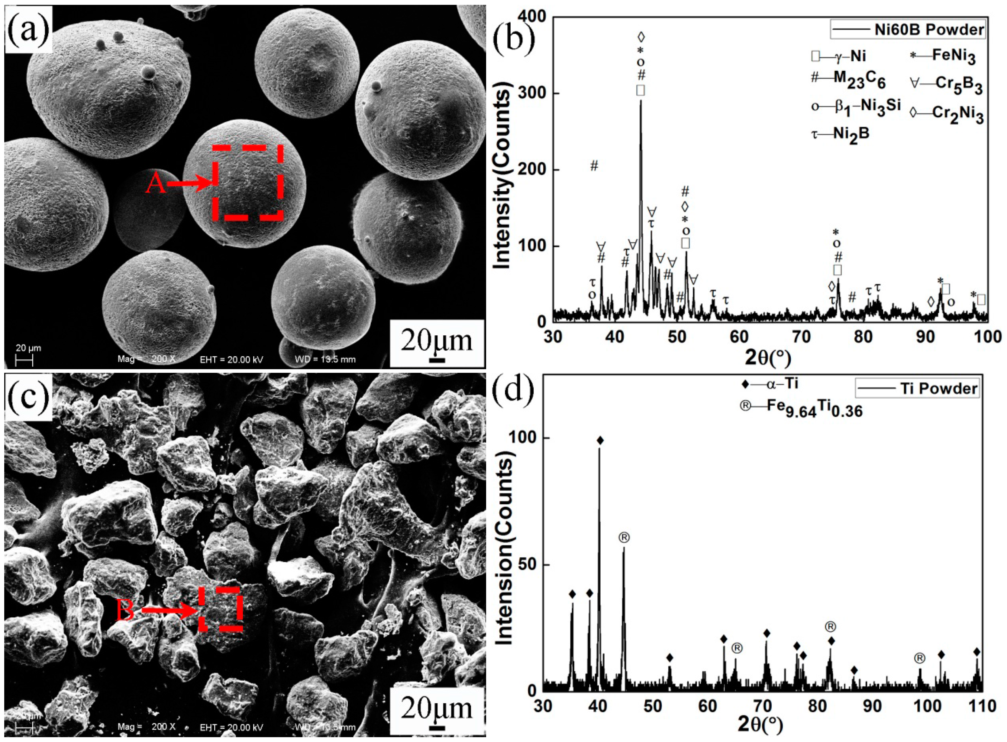
Hot work mould steel H13 was chosen as the substrate, and its chemical compositions are shown in Table 1. Ni60B and Ti powders were used as plasma spray welding materials, which were produced by Beijing General Research Institute of Mining & Metallurgy of China. The morphologies, X-ray diffraction (XRD), and energy dispersive spectroscopy (EDS) characterizations of the powders are shown in Figure 1 and Table 2, respectively. It can be seen that Ni60B powder presented in nearly spherical shape, which consisted of γ-Ni, (Cr,Fe)23C6, β1-Ni3Si, Ni2B, FeNi3, Cr5B3, and Cr2Ni3. Ti powder presented in irregular shape and mainly consisted of α-Ti and a small amount of Fe9.64Ti0.36.
In this investigation, 100% Ni60B powder and 85% Ni60B + 15% Ti powders were taken as spray materials, and were labeled as No.1 and No.2, respectively. No.2 powders were mixed by a planetary ball mill (QXQM-4: Company of Mining Machine Equipment, Nanchang, China) for an hour to achieve homogeneous state. The plasma spray welding was carried out using a plasma spray welding system (GAP 2001 DC: Castolin GmbH, Germany) with Ni60B and mixed powders. A plasma spray welding torch operates with two independently adjustable arcs: the transferred arc and the no-transferred arc. The transferred arc was ignited with the aid of a high-frequency voltage and then the no-transferred arc was established between torch and steel substrate, which was used as the energy source for spray welding. Prior to the spray welding, the steel substrate surface was thoroughly cleaned and then rinsed by acetone. The plasma spray welding parameters are given in Table 3. The shielding gases were Ar for No.1 powder and N2 for No.2 powder, respectively.
After spray welding, the coating specimens for microstructure study and abrasive test were cut down from the welded H13 substrate. The microstructures and compositions of the coatings were examined by using scanning electron microscope (SEM, EVO18: LaiSe Spectrum Technology Co. Ltd., Shanghai, China) coupled with EDS (Link-ISIS), XRD (Rigaku Corporation, Japan, D/Max 2500PC, λCuKα = 0.15418 nm, 4°/min). The Vickers micro-hardness of the coatings was tested with a load of 500 g and a duration of 10 s. A wheel grinder (ML-100: JiNan YiHua Tribology Testing Technology Co. Ltd., Jinan, China) was used for wear test of the coatings with abrasive paper 600# under the load of 10 N. The wear resistance of the coatings was evaluated based on their weight loss.
3. Results and Discussion
3.1. Microstructures of Plasma Spray Welded Coating
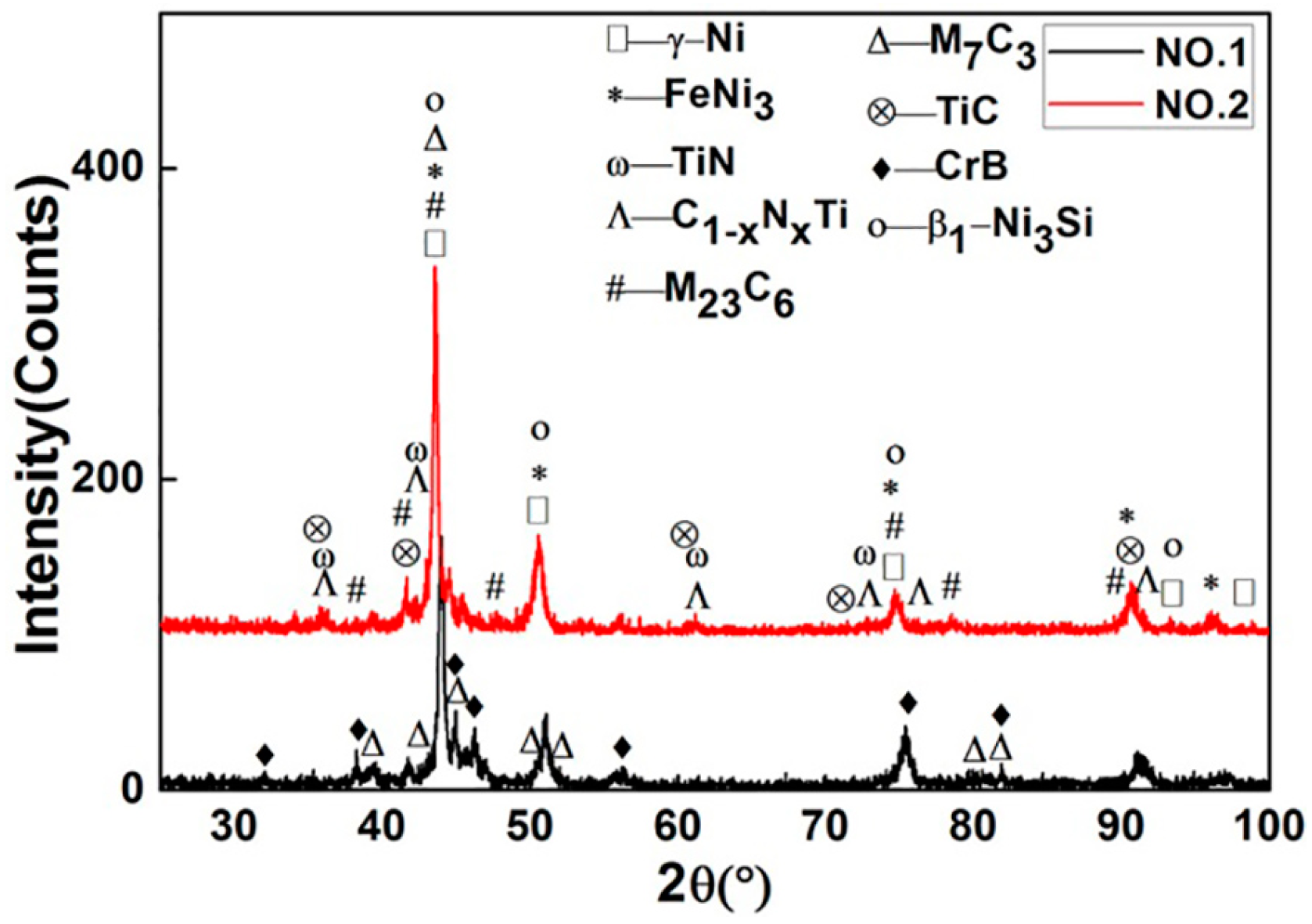
Figure 2 shows XRD patterns of specimens No.1 and No.2, respectively. The phases of γ-Ni, FeNi3, β1-Ni3Si, CrB, Cr7C3, (Cr,Fe)7C3, Cr23C6, and (Cr,Fe)23C6 were identified in the coatings of both No.1 and No.2. From the XRD comparison of No.1 coating and Ni60B powder, new phase CrB was formed but Cr5B3 and Cr2Ni3 disappeared after plasma spray welding. In the coating of No.2, a large amount of TiN, C1-xNxTi, and a small amount of TiC were found, which derived from gas-solid in-situ reaction. Both TiN and TiC have cubic atomic crystal structure and similar lattice constants. Further, C and N atoms have similar radius. Therefore, element C can be combined with TiN infinitely to form C1-xNxTi. The experiment proved that these hard phases greatly increased the wear resistance of the coating. Further study revealed that FeNi3 and β1-Ni3Si decreased in the No.2 coating compared with 85% Ni60B + 15% Ti powder. As a kind of hard and brittle phase, the decrease of β1-Ni3Si can also improve the wear resistance of the coating.
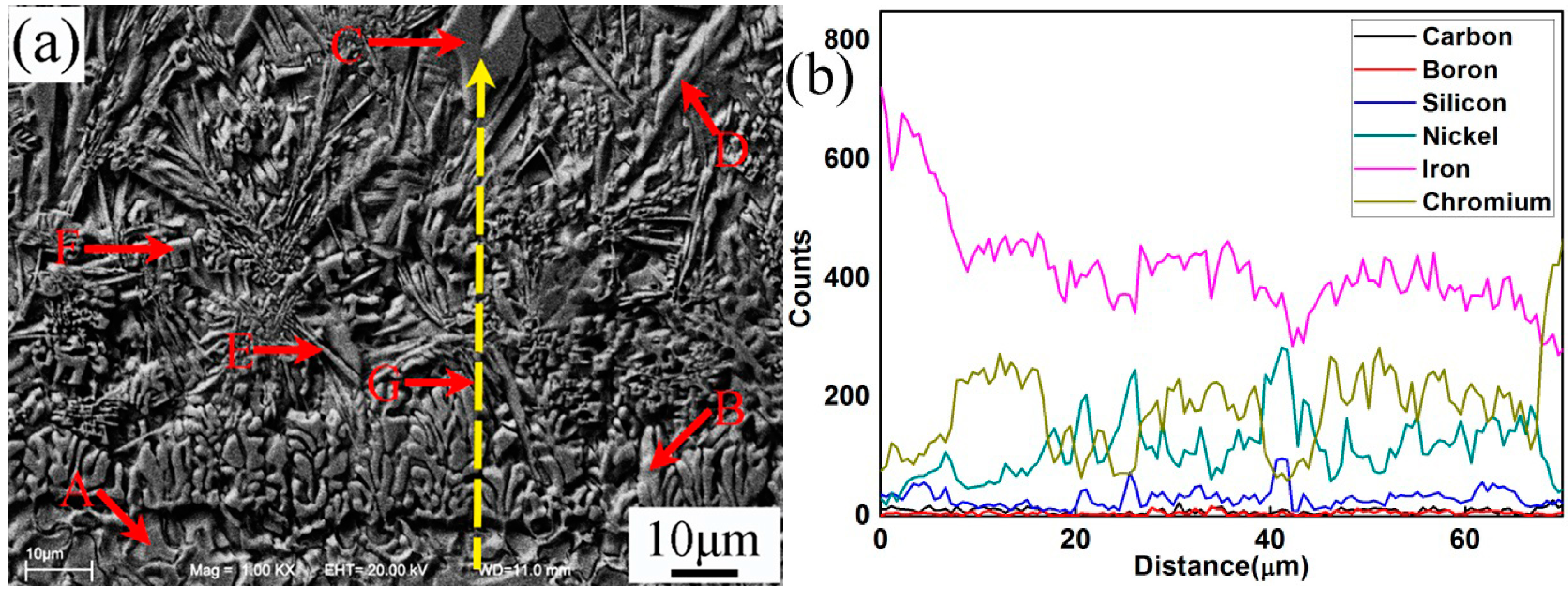
Figure 3 and Table 4 present the SEM microstructure and EDS analysis of No.1 interface between coating and steel substrate, respectively. It could be observed that the coating and substrate formed metallurgical bonding. The width of the fusion zone (Figure 3a) was about 8–10 μm. According to the EDS line scanning analysis, the substrate was rich in element Fe, which gradually decreased from interface to the top coating. This also indicated that element Fe in substrate diffused into the coating during the process of plasma spray welding. In contrast, the EDS analysis showed that the proportion of elements Ni, Cr, B, and Si in the coating were higher than that in the substrate. From Figure 3a, the coating consisted of columnar grains (B) and irregular carbon precipitates (C, D, E, and F) which were embedded in the matrix. Based on the XRD and EDS results, it could be identified that the matrix of the coating was mainly Ni3Si, γ-Ni, and FeNi3. The long flakiness shaped carbon precipitates D and irregularly shaped carbon precipitates with holes C were (Cr,Fe)7C3. However, carbon precipitates D had higher Fe and lower Cr content than that of carbon precipitates C. Both the needle shaped carbon precipitates E and irregular flakiness shaped carbon precipitates F were (Cr,Fe)23C6, but carbon precipitates E had higher Fe and lower Cr content than that of microstructure F. It could be concluded that the lower Fe content in (Cr,Fe)7C3 or (Cr,Fe)23C6 contributed to decreasing the size of the microstructures, which would increase the wear resistance of the plasma spray welded coatings.
Figure 4 presents the SEM microstructure and EDS analysis of the middle part of plasma spray welded specimen No.1. Based on the XRD and EDS results, different shape microstructures were identified as in Table 5. Combined with phase diagram study, it could be concluded that during the process of plasma spray welding, (Cr,Fe)7C3 and (Cr,Fe)23C6 first nucleated about 1766 °C and 1576 °C, respectively. The phase γ-(Ni,Fe) precipitated at about 1440 °C and then partly transformed to eutectic microstructures β3-Ni3Si + γ-Ni at about 1143 °C, which would turn into β1-Ni3Si + γ-Ni with temperature further lowering. When the welding pool reached about 517 °C, phase γ-(Ni,Fe) at high temperature transformed into phase FeNi3, which could only exist at low temperature.
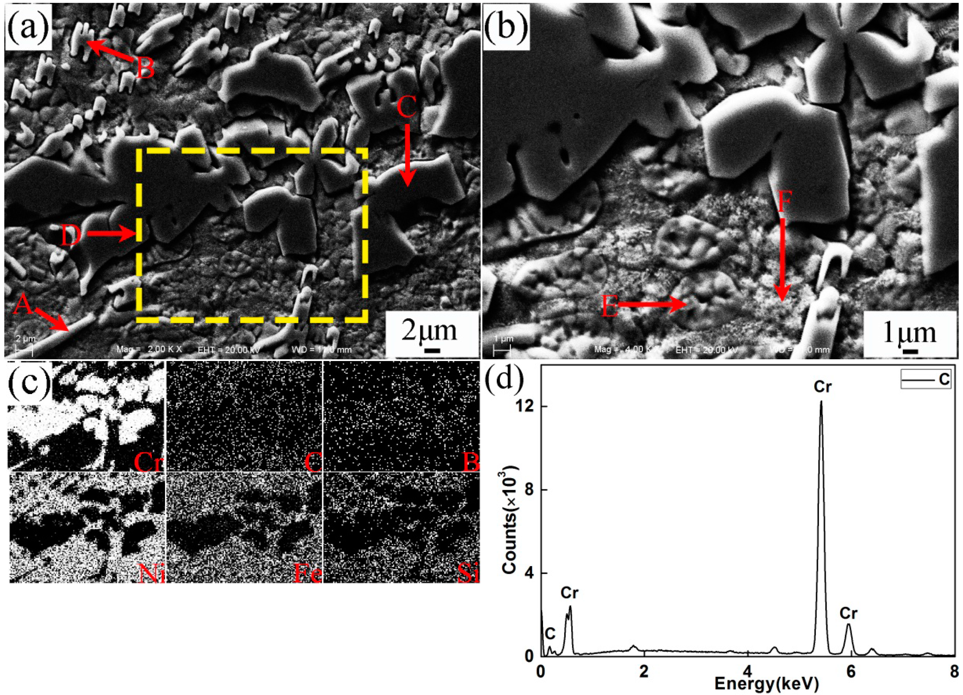
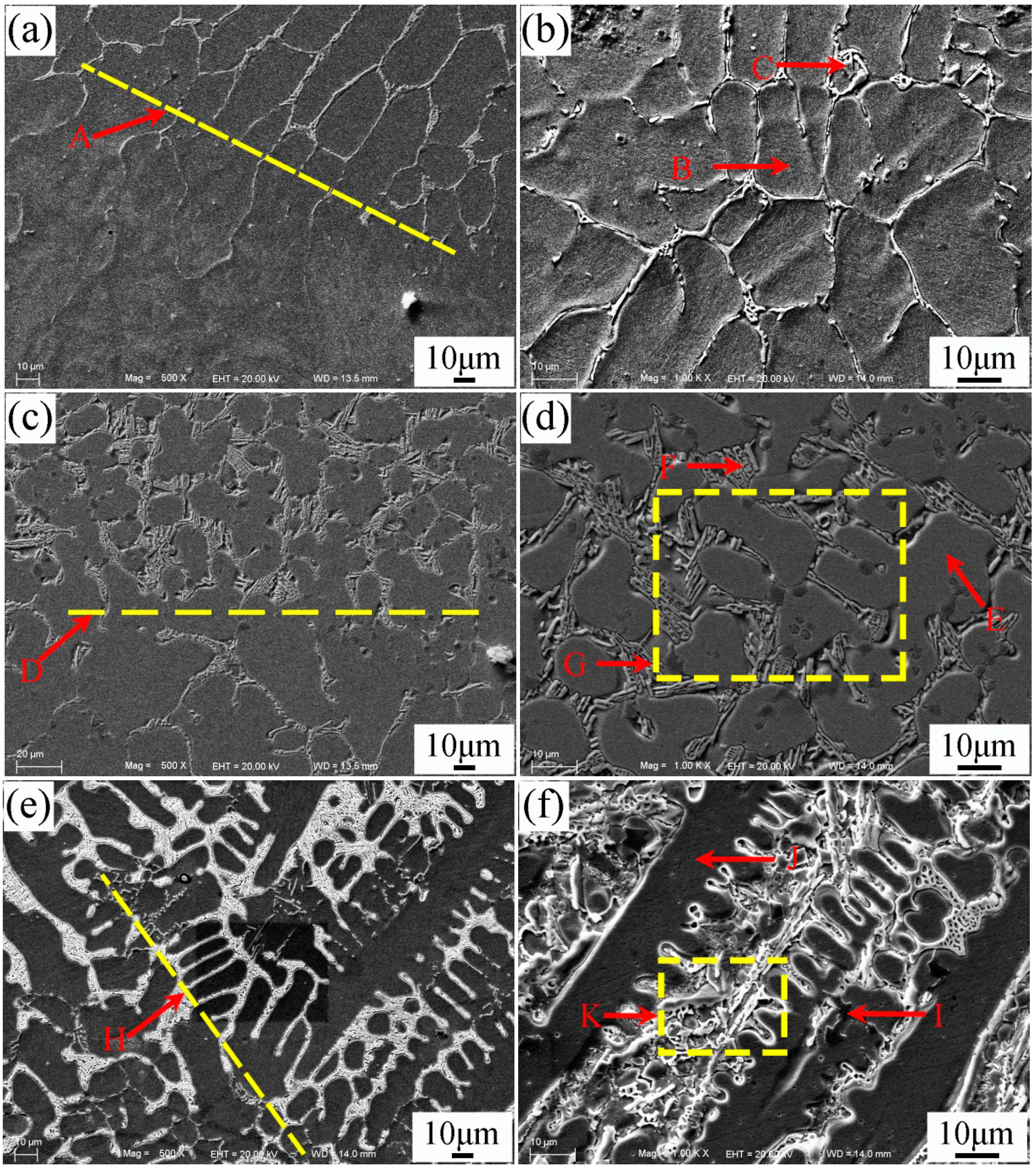
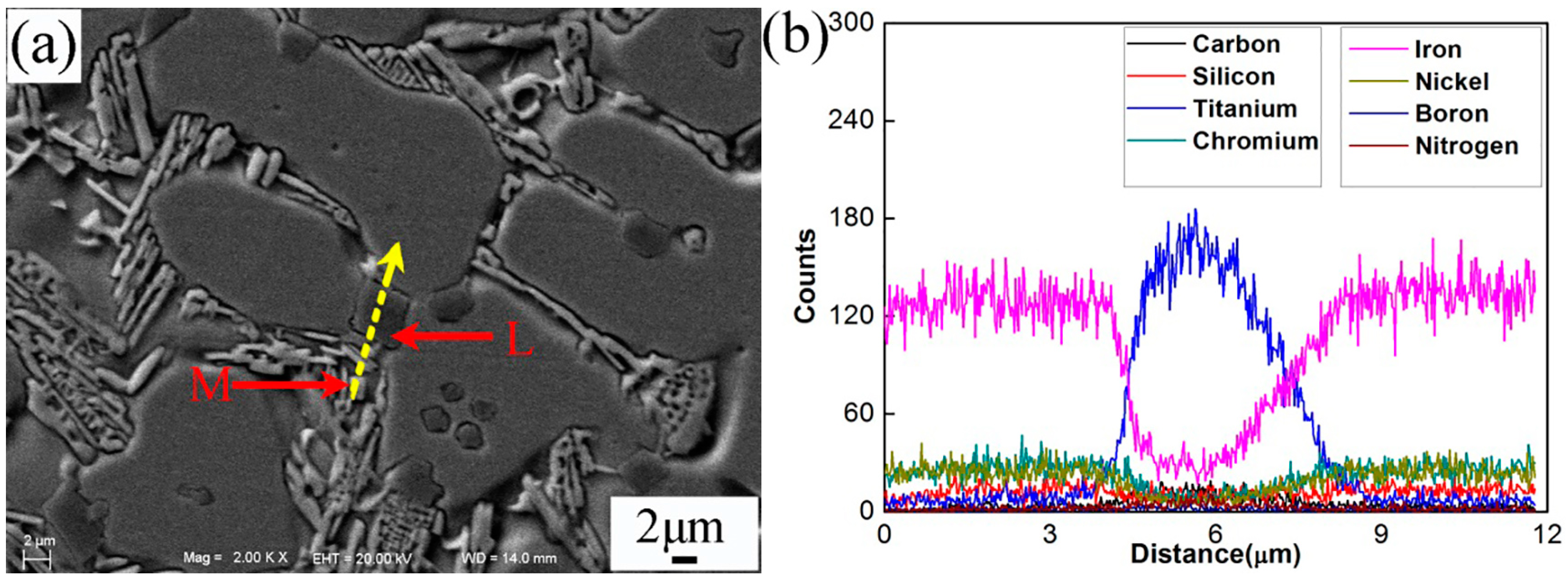
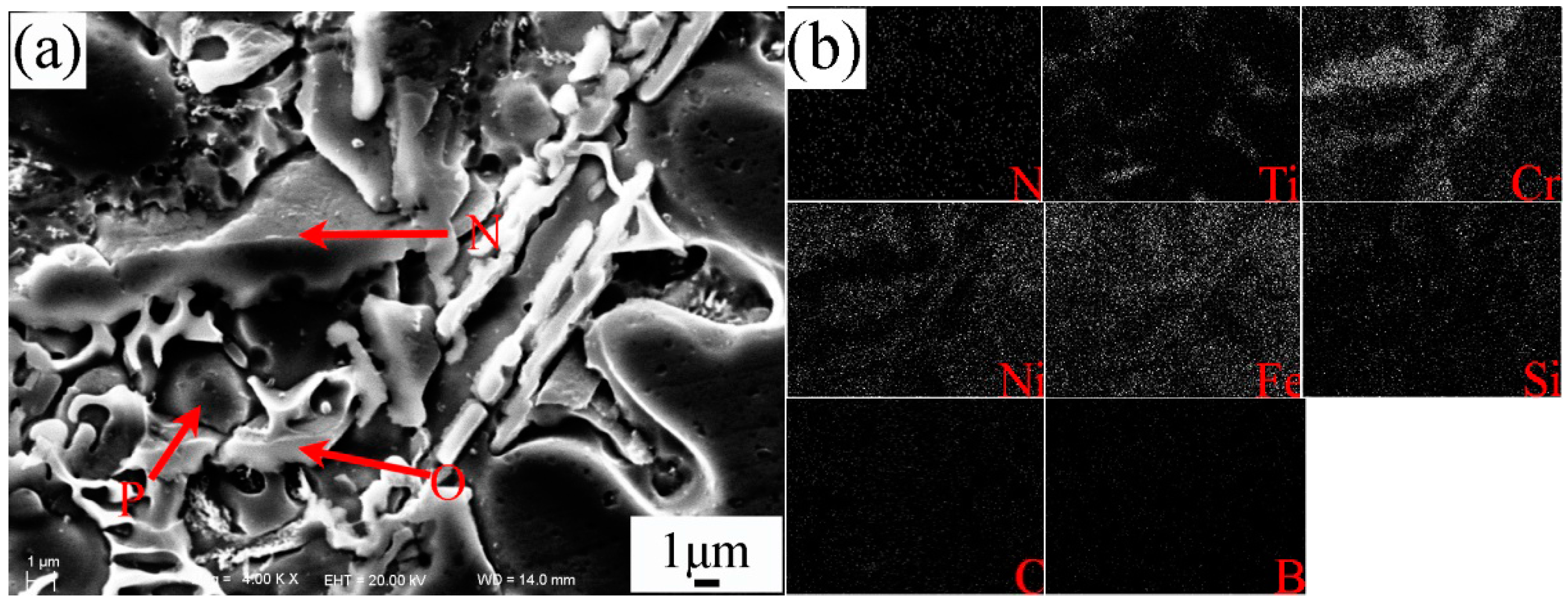
Figure 5a–f shows the SEM morphologies of the interfacial zone between substrate and coating of specimen No.2. The magnification and EDS analysis of locations G and K in Figure 5 were presented in Figure 6 and Figure 7, respectively. The EDS analysis results of Figure 5, Figure 6 and Figure 7 are shown in Table 6. The yellow line A in Figure 5a could be seen as the bottom boundary of heat-affected substrate. Figure 5b shows the morphology of partly melted substrate. Due to the thermal effect of the plasma process, the grains B in this region coarsened. The chemical elements Fe, Cr, Ni, and C were detected in the grain boundary precipitates C, which could be attributed to the diffusion of the elements in the coating. The yellow line D in Figure 5c can be seen as the boundary between the melted substrate and coating. Adjacent to the line D, cellular grains could be observed as shown in Figure 5d. The study demonstrated that the content of chemical elements Cr, Mo, V, and C in grain boundary precipitates obviously increased due to the formation of metal carbides. Based on the EDS results, the deep bulk shape microstructure L in Figure 6 was hard phase TiC. This also indicated that the melted spray welding powders mixed with melted substrate in this area. The yellow line H in Figure 5e can be seen as the boundary of cellular grains and dendrite grains, as shown in Figure 5f. According to the analysis results, bulk shape microstructures N and P were (Cr,Fe)7C3 and FeNi3, respectively. The black lump shape titanium carbonitrides I in Figure 5f was C1-xNxTi. Further study had found that there was a large amount of C1-xNxTi and TiC between the secondary dendrite grains. From the EDS results, the content of Fe in partly melted grains, cellular grains, and dendrite grains gradually decreased, but the content of Cr, Ni, and C gradually increased. This was attributed to the dilution effect weakening of the melted substrate on the coating. The microstructures in yellow line K was presented in Figure 7. The analysis proved that carbon precipitates N, O, and intermetallic phase P in Figure 7a were (Cr,Fe)7C3, TiC + FeNi3, and FeNi3, respectively. Especially, the formation of TiC in the coating greatly improved the hardness and wear resistance of the coating.
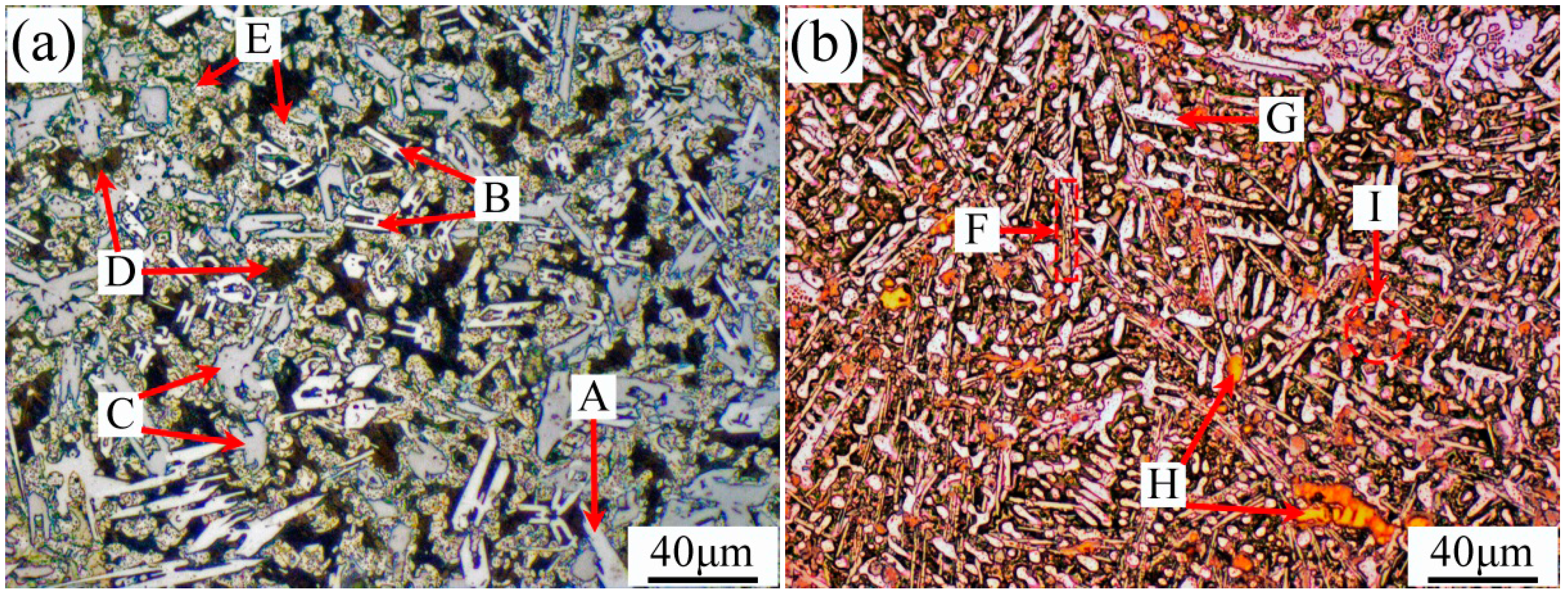
The microstructures of the top coatings of specimens No.1 and No.2 are shown in Figure 8. Based on the SEM and XRD analyses, it could be concluded that the long white carbon precipitates A and F were (Cr,Fe)23C6, “H” shape carbon precipitate B was (Cr,Fe)7C3, irregular flake-like carbon precipitate C was Cr23C6, and black matrix D was β1-Ni3Si + γ-Ni. Further investigation revealed that the clump precipitates of intermetallic phases E and G were FeNi3, yellow precipitates of nitrides and titanium carbonitrides H and I were TiN and C1-xNxTi. Compared with the microstructures of specimen No.1, the microstructures of specimen No.2 were fine due to the generation of the small particles of TiN, C1-xNxTi, and TiC from in-situ solid-gas reaction, the size of which usually varied from 10–40 μm.
3.2. The Properties of Plasma Spray Welded Coating
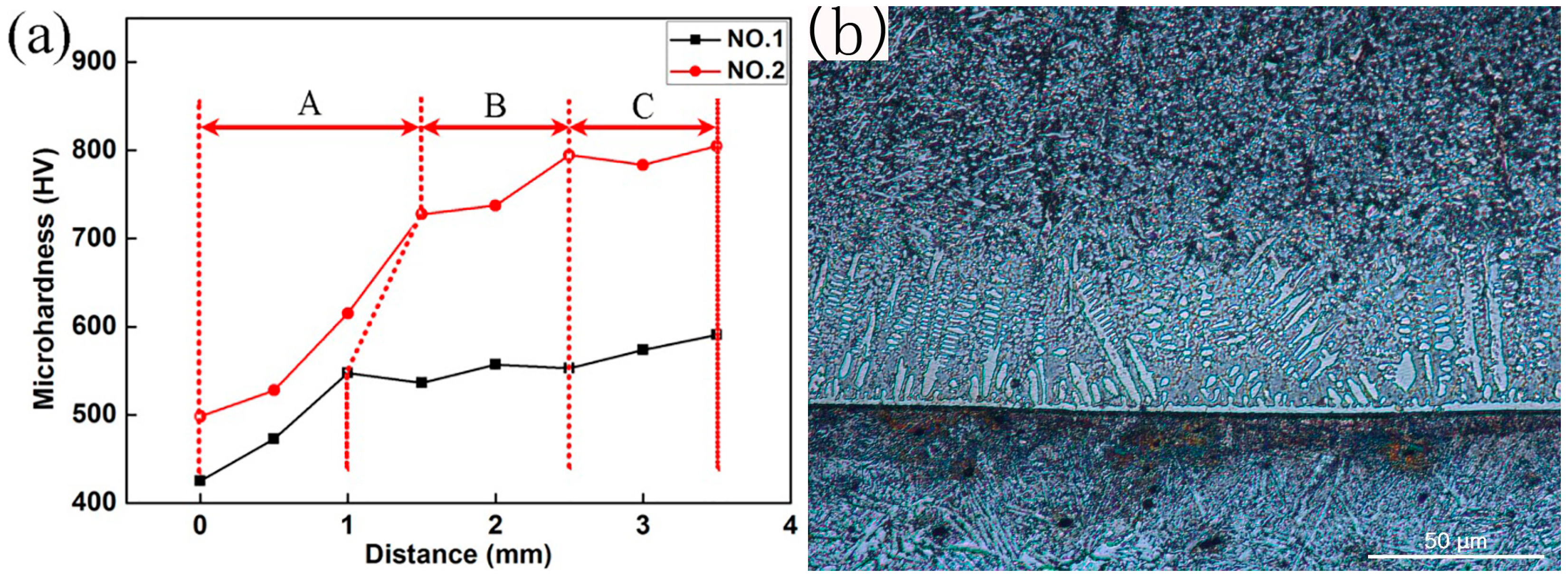
The micro-hardness of the plasma spray welded coating is shown in Figure 9. The fusion line was taken as the “zero”, and the hardness of the different points from the fusion line to the top of the coating was measured. Generally, the welded coating can be divided into three parts: the bottom A, the middle B, and the top C. From Figure 9, the bottom A had the lowest hardness, which was mainly attributed to the dilution effect of the substrate material. From the middle part B to the top part C, the hardness of the coating gradually increased because of the rise of the amount of hard phase. The hardness of specimen No.2 was higher than that of specimen No.1, which was attributed to the generation of small particles of TiN, C1-xNxTi, and TiC from in-situ solid-gas reaction.
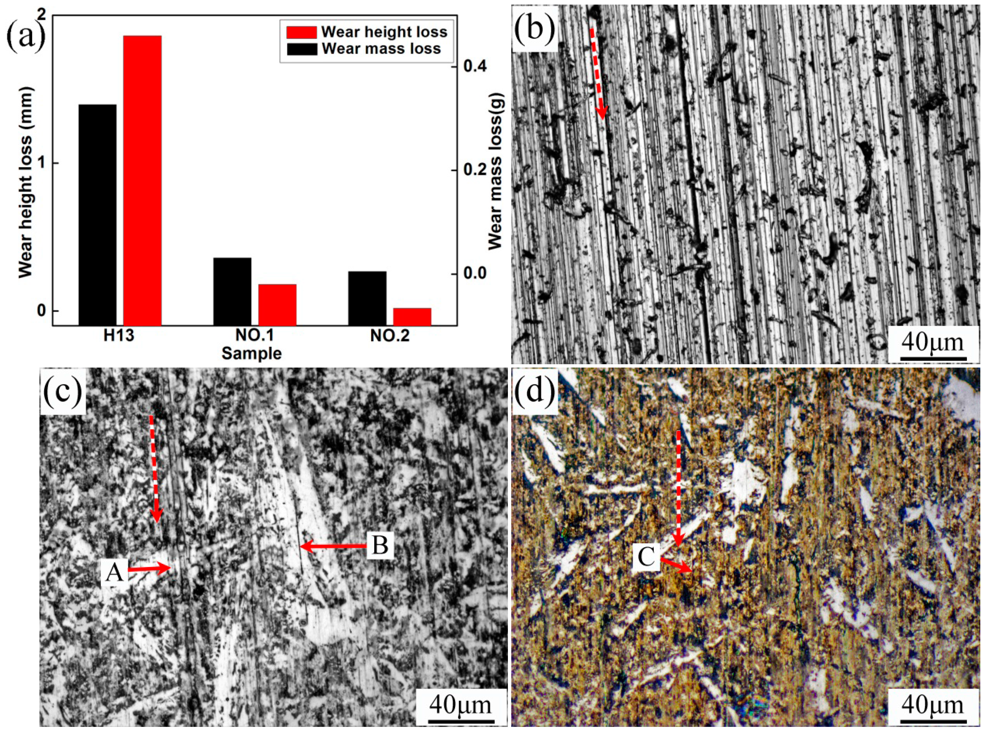
The wear resistance tests for H13, specimens No.1 and No.2 were conducted in this study. The wear resistances of the specimens were evaluated by their height and weight loss before and after tests, as shown in Figure 10. Obviously, specimen No.2 had the best wear resistance. The surface morphologies of the specimens after test are presented in Figure 10b–d. The red dashed lines indicate the direction of the wear test. The plowing mark and plastic deformation were deeper and larger in the surface of specimen H13, but shallower and smaller in the surface of specimens No.1 and No.2 after the wear tests. This also conformed to the wear test results. The investigation demonstrated that fine and hard phases TiN and C1-xNxTi could effectively alleviate the plowing and cutting behavior.
4. Conclusions
The metallurgical bonding between the Ni-based coating and steel HB substrate were formed during the plasma spray welding. The microstructures of the coating mainly included (Cr,Fe)23C6, (Cr,Fe)7C3, β1-Ni3Si + γ-Ni, FeNi3, TiN, C1-xNxTi, etc. For the coating prepared with powders 85% Ni60B + 15% Ti, a lot of fine hard phases such as TiN, C1-xNxTi, and TiC generated from in-situ solid-gas reaction uniformly dispersed in the coating and greatly enhanced the hardness and wear resistance of the coating. The average microhardness of the coating prepared with 85% Ni60B + 15% Ti powders reached 900 HV0.5, and the average wear resistance of the coating was three times that of the coating prepared with 100% Ni60B powder and six times that of the H13 steel substrate.
Acknowledgments
This work is supported by the National Natural Science Foundation of China (NNSFC, No. 51571101).
Author Contributions
Wenquan Wang and Hongyong Xu conceived and designed the experiments; Hongyong Xu performed the experiments and analyzed the data; Wang Wenquan and Li Wenmo wrote the paper.
Conflicts of Interest
The authors declare no conflict of interest.
References
- Tekmen, C.; Ozdemir, I.; Fritsche, G.; Tsunekawa, Y. Structural evolution of mechanically alloyed Al-12Si/TiB2/h-BN composite powder coating by atmospheric plasma spraying. Surf. Coat. Technol. 2009, 203, 2046–2051. [Google Scholar] [CrossRef]
- Ingo, G.M.; Kaciulis, S.; Mezzi, A.; Valente, T.; Casadei, F.; Gusmano, G. Characterization of composite titanium nitride coatings prepared by reactive plasma spraying. Electrochim. Acta 2005, 50, 4531–4537. [Google Scholar] [CrossRef]
- Kodama, T.; Ikeda, Y.; Tamura, H. Reactive thermal spray by high velocity ceramic jet and characterization of the coatings. J. Therm. Spray Technol. 1999, 8, 537–544. [Google Scholar] [CrossRef]
- Borgioli, F.; Galvanetto, E.; Galliano, F.P.; Bacci, T. Sliding wear resistance of reactive plasma sprayed Ti-TiN coatings. Wear 2006, 260, 832–837. [Google Scholar] [CrossRef]
- Mao, Z.; Wang, J.; Sun, B.; Yao, C. Properties of reactive plasma sprayed TiB2-TiC0.3N0.7 based composite coatings with Cr addition and laser surface treatment. J. Therm. Spray Technol. 2009, 18, 563–571. [Google Scholar] [CrossRef]
- Xiao, L.S.; Yan, D.R.; He, J.N.; Lin, Z.; Dong, Y.C.; Zhang, J.X.; Li, X.Z. Nanostructured TiN coating prepared by reactive plasma spraying in atmosphere. Appl. Surf. Sci. 2007, 253, 7535–7539. [Google Scholar] [CrossRef]
- Rosu, R.A.; Serban, V.A.; Bucur, A.I.; Dragos, U. Deposition of titanium nitride and hydroxyapatite-based biocompatible composite by reactive plasma spraying. Appl. Surf. Sci. 2012, 258, 3871–3876. [Google Scholar] [CrossRef]
- Yuan, Y.; Li, Z. Effects of rod carbide size, content, loading and sliding distance on the friction and wear behaviors of (Cr,Fe)7C3-reinforced α-Fe based composite coating produced via PTA welding process. Surf. Coat. Technol. 2014, 248, 9–22. [Google Scholar] [CrossRef]
- Shanmugavelayutham, G.; Yano, S.; Kobayashi, A. Microstructural characterization and properties of ZrO2/Al2O3 thermal barrier coatings by gas tunnel-type plasma spraying. Vacuum 2006, 80, 1336–1340. [Google Scholar] [CrossRef]
- Li, C.-J.; Li, J.-L. Evaporated-gas-induced splashing model for splat formation during plasma spraying. Surf. Coat. Technol. 2004, 184, 13–23. [Google Scholar] [CrossRef]
- Ye, F.X.; Tsumura, T.; Nakata, K.; Ohmori, A. Dependence of photocatalytic activity on the compositions and photo-absorption of functional TiO2-Fe3O4 coatings deposited by plasma spray. Mater. Sci. Eng. B 2008, 148, 154–161. [Google Scholar] [CrossRef]
- Tekmen, C.; Tsunekawa, Y.; Okumiya, M. In-situ TiB2 and Al2O3 formation by DC plasma spraying. Surf. Coat. Technol. 2008, 202, 4170–4175. [Google Scholar] [CrossRef]
- Hoshiyama, Y.; Miyake, H.; Murakami, K.; Nakajima, H. Composite deposits based on titanium aluminide produced by plasma spraying. Mater. Sci. Eng. A 2002, 333, 92–97. [Google Scholar] [CrossRef]
- Chen, G.Q.; Fu, X.S.; Wei, Y.H.; Li, S.; Zhou, W.L. Microstructure and wear properties of nickel-based surfacing deposited by plasma transferred arc welding. Surf. Coat. Technol. 2013, 228, S276–S282. [Google Scholar]
Figure 1.
Morphologies and XRD patterns of (a,b) Ni60B and (c,d) Ti powders.

Figure 2.
XRD patterns of No.1 and No.2 specimen coatings (0.0 < x < 1.0).

Figure 3.
SEM and EDS of interfacial zone of specimen No.1. (a) Microstructures of the coating and substrate for specimen No.1 (SEM); (b) EDS of interfacial zone of specimen No.1
Figure 3.
SEM and EDS of interfacial zone of specimen No.1. (a) Microstructures of the coating and substrate for specimen No.1 (SEM); (b) EDS of interfacial zone of specimen No.1

Figure 4.
SEM and EDS of coating of specimen No. 1. (a) Microstructures of the coating for specimen No.1 (SEM); (b) Magnification of D zone; (c) The chemical elements in specimen No.1; (d) EDS of location C.
Figure 4.
SEM and EDS of coating of specimen No. 1. (a) Microstructures of the coating for specimen No.1 (SEM); (b) Magnification of D zone; (c) The chemical elements in specimen No.1; (d) EDS of location C.

Figure 5.
SEM of the interfacial zone of specimen No.2. (a) Heat affected zone; (b) Morphology of partly melted substrate; (c) Interface of melted substrate and coating; (d) Cellular grains and boundary precipitates; (e) Interface of cellular grains and dendrite grains; (f) Dendrite grains of the coating.

Figure 6.
Magnified SEM of point G in Figure 5 and line scan of location M. (a) SEM of magnified cellular grains and boundary precipitates; (b) EDS of line M.
Figure 6.
Magnified SEM of point G in Figure 5 and line scan of location M. (a) SEM of magnified cellular grains and boundary precipitates; (b) EDS of line M.

Figure 7.
Magnification of area K in Figure 5 and area scan of Figure 5a. (a) SEM of magnified dendrite grains of the coating (b) The chemical elements in specimen No.2.

Figure 8.
Top coating microstructures of specimens (a) No.1 and (b) No.2.

Figure 9.
Microhardness of the coating: (a) cure of hardness; (b) microstructures of the coating and substrate No.1.
Figure 9.
Microhardness of the coating: (a) cure of hardness; (b) microstructures of the coating and substrate No.1.

Figure 10.
Wear resistance test results: (a) weight and height loss; (b) H13; (c) No.1; (d) No.2.


Table 1.
H13 Chemical compositions (wt %).
| Cr | Mo | Si | V | C |
| 4.75–5.50 | 1.10–1.75 | 0.80–1.20 | 0.80–1.20 | 0.32–0.45 |
| Mn | S | P | Fe | |
| 0.20–0.50 | ≤0.03 | ≤0.03 | Surplus |
Table 2.
Energy dispersive spectroscopy (EDS) analysis of powders.
| Element | Ni | Cr | B | Si | Fe | C | Ti | |
|---|---|---|---|---|---|---|---|---|
| A | at% | 46.81 | 13.72 | 16.82 | 7.04 | 11.83 | 3.78 | - |
| B | at% | - | - | - | - | 9.13 | - | 90.87 |
Table 3.
Parameters of plasma spray welding.
| Non-Transferred Arc (A) | Transferred Arc (A) | Voltage (V) | Powder Feeding Rate | Spray Speed (mm/min) |
| 10 | 50 | 33 (45) | 30% | 35 |
| Powder Feeding (g/min) | Spray Distance (mm) | Plasma Gas Ar (L/min) | Shielding gas Ar (L/min) | Carrier Gas (L/min) |
| 6.48–6.63 | 11 | 0.5 | 10 | 4 |
Table 4.
EDS results of different points in Figure 3a (at %).
Table 4.
EDS results of different points in Figure 3a (at %).
| Position | Phase | C | Cr | Ni | Fe | Si | Mo | V |
|---|---|---|---|---|---|---|---|---|
| A | γ-(Ni,Fe) | 10.53 | 6.28 | 9.34 | 69.63 | 3.36 | 0.53 | 0.33 |
| B | γ-(Ni,Fe) | 9.10 | 11.85 | 15.96 | 58.67 | 3.92 | 0.16 | 0.25 |
| C | (Cr,Fe)7C3 | 35.49 | 31.41 | - | 33.10 | - | - | - |
| D | (Cr,Fe)7C3 | 30.53 | 24.11 | 7.32 | 38.04 | - | - | - |
| E | (Cr,Fe)23C6 | 18.11 | 24.24 | 7.13 | 50.52 | - | - | - |
| F | (Cr,Fe)23C6 | 13.51 | 32.20 | 9.22 | 43.51 | 0.94 | - | - |
Table 5.
EDS results of different points in Figure 4a (at %).
Table 5.
EDS results of different points in Figure 4a (at %).
| Element | Phase | C | Cr | Ni | Fe | Si |
|---|---|---|---|---|---|---|
| A | (Cr,Fe)23C6 | 18.21 | 45.24 | 4.33 | 32.22 | - |
| B | (Cr,Fe)7C3 | 34.88 | 45.93 | 4.74 | 14.46 | - |
| C | Cr23C6 | 9.32 | 83.72 | 1.38 | 5.58 | - |
| E | FeNi3 | 7.73 | - | 55.32 | 24.74 | 12.21 |
| F | (Ni3Si + γ-Ni) | 9.09 | 2.41 | 59.82 | 9.80 | 18.87 |
| Element | Phase | Ti | N | C | Cr | Ni | Fe | Si | Mo | V |
|---|---|---|---|---|---|---|---|---|---|---|
| B | γ-Fe | - | - | 4.11 | 5.00 | 3.40 | 84.51 | 2.03 | 0.43 | 0.51 |
| C | - | - | 15.89 | 7.06 | 9.54 | 63.83 | 2.61 | 0.45 | 0.61 | |
| E | γ-Fe | 0.37 | - | 11.13 | 6.70 | 12.28 | 65.56 | 3.43 | 0.24 | 0.29 |
| F | 7.56 | - | 10.62 | 19.19 | 6.77 | 49.76 | 1.07 | 2.74 | 2.29 | |
| I | C1-xNxTi | 48.10 | 45.83 | 6.07 | - | - | - | - | - | - |
| J | γ-Fe | 1.16 | - | 13.42 | 8.85 | 19.54 | 52.32 | 4.38 | 0.12 | 0.21 |
| L | TiC | 47.72 | - | 52.28 | - | - | - | - | - | - |
| N | (Cr,Fe)7C3 | - | - | 22.38 | 20.69 | 15.57 | 41.36 | - | - | - |
| O | TiC + FeNi3 | 16.24 | - | 21.42 | 7.93 | 15.21 | 39.19 | - | - | - |
| P | FeNi3 | 1.84 | - | 10.04 | 8.43 | 30.06 | 45.82 | 3.81 | - | - |
© 2017 by the authors. Licensee MDPI, Basel, Switzerland. This article is an open access article distributed under the terms and conditions of the Creative Commons Attribution (CC BY) license (http://creativecommons.org/licenses/by/4.0/).
Share and Cite
MDPI and ACS Style
Wang, W.; Li, W.; Xu, H. Microstructures and Properties of Plasma Sprayed Ni Based Coatings Reinforced by TiN/C1-xNxTi Generated from In-Situ Solid-Gas Reaction. Materials 2017, 10, 785. https://doi.org/10.3390/ma10070785
AMA Style
Wang W, Li W, Xu H. Microstructures and Properties of Plasma Sprayed Ni Based Coatings Reinforced by TiN/C1-xNxTi Generated from In-Situ Solid-Gas Reaction. Materials. 2017; 10(7):785. https://doi.org/10.3390/ma10070785
Chicago/Turabian StyleWang, Wenquan, Wenmo Li, and Hongyong Xu. 2017. "Microstructures and Properties of Plasma Sprayed Ni Based Coatings Reinforced by TiN/C1-xNxTi Generated from In-Situ Solid-Gas Reaction" Materials 10, no. 7: 785. https://doi.org/10.3390/ma10070785
Note that from the first issue of 2016, this journal uses article numbers instead of page numbers. See further details here.