
Formative and Summative Validation of Building Information Model-Based Cadastral Data


The Centre for Spatial Data Infrastructures and Land Administration, Department of Infrastructure Engineering, The University of Melbourne, Melbourne, VIC 3010, Australia
*
Author to whom correspondence should be addressed.
Land 2021, 10(8), 822; https://doi.org/10.3390/land10080822
Submission received: 28 June 2021
/
Revised: 30 July 2021
/
Accepted: 2 August 2021
/
Published: 5 August 2021
(This article belongs to the Special Issue 3D Cadastre)
Abstract
:Among 3D models, Building Information Models (BIM) can potentially support the integrated management of buildings’ physical and legal aspects in cadastres. However, there is not a systematic approach to author the cadastral information into the BIM models. Moreover, the common approaches for data validation only check the final cadastral output, and they ignore the data generation steps as potential avenues for validation. Therefore, this study aims to develop the criteria and standards to check the spatial consistency and integrity of BIM-based cadastral data in the process of generating the data. The paper utilises a case study approach as its methodology to investigate the requirements of generating a BIM-based cadastral model and identify the issues within the process. The results include a formative assessment (i.e., multistep validation approach during the data generation) alongside a summative assessment (i.e., one-step validation approach at the end of data generation). This study found the summative assessment alone insufficient for 3D cadastral data validation. The paper concludes that a formative and summative assessment together can improve the validity of the data. The results will potentially bring more efficiency to modern land administration processes by avoiding the accumulation of errors in 3D cadastral data generation.
1. Introduction
The widespread use of 3D geospatial data models representing the real world’s physical entities provides a powerful means for a 2D cadastre transition to the 3D digital environment. Previous studies showed that a 3D digital representation of a cadastral system would provide an efficient process to record and analyse cadastral information [1,2,3,4,5,6,7,8]. This 3D digital system would facilitate communicating spatial and legal information related to complicated situations in the urban built environment [9].
3D models facilitate exchanging and sharing information across the building development process and within the building’s lifecycle. Architectural plans are used in an early stage of designing a building development. Although the architectural plan is still based on 2D floor plans in many countries, in some countries like South Korea, proposing a 3D model such as a Building Information Model (BIM) for every new development is mandatory [10]. Using 3D models is also becoming mandatory in many European countries, and there is a lot of interest in the development and adoption of such digital procedures. However, the degree of BIM adoption and maturity varies across the world. The introduction of the BIM methods is already quite advanced in some countries. Singapore, Finland, South Korea, the USA, the UK and Australia are among the pioneers [11].
Architectural plans can also be used as a basis for developing the cadastral plans of buildings. For example, 2D design-based architectural plans are commonly used by surveyors for generating a plan of subdivision in Victoria, Australia. A subdivision plan is a legal document including survey data for representing the precise extent of private properties and common property areas. Due to the growing use of 3D models for designing new building developments, the possibility of using these models in land administration for developing 3D digital cadastral data models has been widely studied. Among 3D models, BIM and, specifically, the Industry Foundation Classes (IFC)—due to having a synergetic, 3D digital and semantically enhanced data environment—provide the potential capabilities for modelling legal and physical dimensions of urban properties. Land administration can benefit from BIM for the meaningful communication of complex 3D ownership spaces defined within multistorey buildings [12]. However, leveraging BIM and IFC for land administration has not been entirely straightforward over its development. Clemen and Gründig [13] demonstrated that IFC data models, due to supporting 3D topology and geometric representation of building elements, could be extended for land surveying purposes. However, they did not provide any solutions for how 3D surveying data elements could be mapped into IFC data models. El-Mekawy and Östman [14] also proposed to enrich Unified Building Models (UBM) with all types of boundaries required to define 3D spaces with Rights, Restrictions and Responsibilities (RRRs) in the context of Swedish jurisdictions. However, the proposed UBM extension was very restricted and did not specify the semantic cadastral information.
Modelling of the ownership boundaries and volumetric ownership spaces using BIM and IFC is not a trivial process. There is no jurisdiction that has formally adopted or recommended using BIM for 3D cadastre. In addition, there is no formal directives by professional associations on this matter. The existing research recommendations are limited to mapping between IFC data elements and 3D cadastral data requirements. No literature, so far, has suggested a systematic approach to author the cadastral information into the BIM models. Moreover, the criteria and validation rules developed for data validation only check the final cadastral output and they ignore the data generation steps as potential avenues for validation.
This study aims to develop validation approaches to check the spatial consistency and integrity of BIM-based cadastral data during and at the end of data generation. To achieve the research aim, the following objectives are formulated in this research:
- Investigating the stages for generating cadastral data using architectural BIM models.
- Identifying the challenges and issues within the process.
- Developing criteria and standards in the form of two assessment approaches.
- Evaluating a cadastral dataset to check the spatial consistency and integrity of data in the ongoing process of data generation.
This paper is organised as follows. In Section 2 the related work for integrating BIM with 3D cadastral information and its validation process are investigated to identify research gaps. Section 3 presents research methodology for identifying the stages to generate the BIM-based cadastral data and developing the criteria for the assessment approaches. In line with the first objective, relevant IFC entities and relationships used for managing legal boundaries and volumetric legal spaces are identified and discussed in Section 3.1. In addition, the paper investigates the relevant cadastral information that should be authored within the BIM models. As part of the third objective, the criteria and standards for authoring 3D cadastral information are also discussed in Section 3.3.2. In Section 4 a cadastral dataset of an existing property is evaluated using the developed assessment approaches, and the results are discussed. In the discussion (Section 5) and conclusions (Section 6), each method’s implication and the future direction of research will be presented, respectively.
2. An Overview of Previous Relevant Studies
Two main approaches are used to integrate BIM with 3D cadastral information: direct and indirect. The direct approach is usually to create a 3D cadastral data model using BIM/IFC based on architectural plans. Atazadeh [15] demonstrated that BIM, particularly IFC, can support the integrated management of physical, semantical, and legal aspects of buildings over their lifecycle. The study showed that the extended IFC standard can be utilised as a rich data model for 3D digital management of spatial and semantic information associated with 3D RRRs in multistorey buildings. In this method, first a range of required cadastral data elements for managing complex ownership spaces was identified based on the ownership spaces and subdivision practices within multistorey buildings in Melbourne, Australia. Subsequently, an open data model in the BIM domain (IFC) was extended with these data elements. For example, to extend the IFC model with legal entities such as private property, common property, and easement, the ‘IfcSpatialZone’ entity was used [16]. In contrast, the existing BIM/IFC model as the physical model was utilised in the indirect method to integrate cadastral information or the legal model [17]. As an indirect method, Oldfield et al. [18] defined requirements to map the Land Administration Domain Model (LADM) and IFC data model. LADM is an international standard which provides a conceptual and formal language for describing both semantic and spatial information associated with RRRs [19]. The IfcSpace entity was mapped to LA_SpatialUnit in LADM. They suggested that the physical IFC models could be manually developed and tailored to land registry requirements.
While this study focuses on the direct method of cadastral data modelling, there is a knowledge gap in the procedure where geometrical and semantical cadastral information is authored within the BIM model. No previous study has investigated the criteria and standards that must be considered for BIM-generated 3D cadastres. Several studies have recently discussed cadastral data validation, and some mathematical and geometrical rules have been developed to check the validity of 3D parcels [20,21,22,23,24,25,26]. For example, Asghari et al. [26] developed validation rules to check the internal spatial consistency of legal spaces with a focus on geometry closure. However, the focus of this study was only on validating the single 3D parcel, and data validation was not considered as a process (i.e., the procedure of generating data and the source of errors were not discussed). As part of the methodology of designing an IFC-based database schema for mapping BIM data into a 3D spatial-enabled land administration database, Barzegar et al. [27] addressed several issues and errors in the legal spaces represented by IfcSpaces. However, there was no discussion on how and why the errors occurred and how these errors could be avoided throughout modelling the legal spaces within BIM authoring software. In these recent studies, neither the process of BIM-based cadastral data generation nor the validation process has been adequately investigated in detail.
The components of BIM geometry must be adapted to the 3D cadastre requirements [28]. BIM data needs to be preprocessed before being used in the 3D cadastre, or a BIM model should be extended to contain the geometry required by the 3D cadastre [29]. When models are checked, having access to both the IFC and the native BIM model is preferred. The common check is always applied to the exported IFC model. However, when shortcomings or deviations in the IFC file are found, it is always good to access the native BIM model to see if the original information was valid. This could be a good temporary solution while waiting for more efficient IFC storage and management, as well as methods for manipulating the IFC data model itself, as this would provide a completely open format-based process. Sometimes the problems identified (e.g., missing component to space relations) are simply due to incorrect IFC-mapping or export settings. Some issues, including incompleteness of the models, inaccuracies such as intersections or gaps among geometries, or geometry deformation, could be confronted while generating and exchanging data among software and people [30]. In the next section, a methodology for generating and validating the BIM-based cadastral data is provided.
3. A Methodology for Generating and Validating BIM-Based Cadastral Data
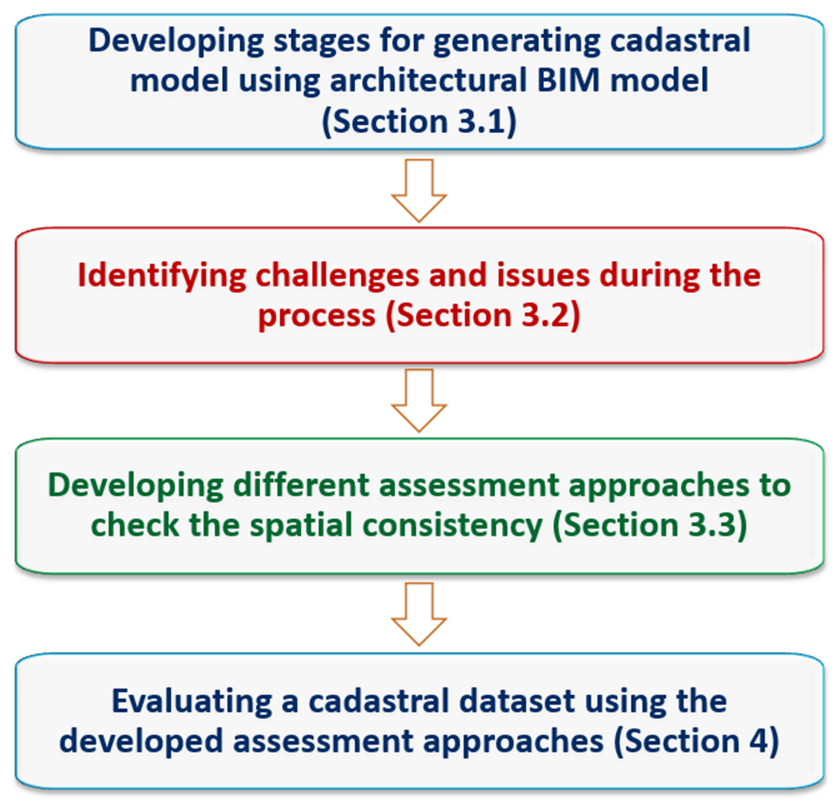
This paper’s methodology utilises a case study approach to investigate the stages for generating cadastral data using architectural BIM models and identify the challenges and issues within the process. Subsequently, different assessment approaches are developed to check the spatial consistency and integrity of data in the ongoing process of data generation. A dataset includes a four-floor residential building with accessibility on both BIM and IFC files is then used for evaluating the developed assessment approaches. It must be noted that the scope of this study is limited to checking the geometry of legal and physical objects within a multistorey building. Investigating the semantical relationship between legal and physical elements is out of the scope of this study. Figure 1 represents the research study steps in a snapshot. Each part of the methodology is discussed separately in relevant sections.
3.1. BIM-Based Cadastral Data Generation
BIM models can be adopted for 3D digital management of data related to complex ownership spaces. Generating the BIM-based cadastral data is, however, a process that includes several stages. In what follows, the main stages required for developing a cadastral data model using BIM models are presented and discussed.
One of the essential phases of a building development process is design development (detailed design) according to regulations, codes, standards, and the project owner’s vision. At this phase, a physical model of a building is designed by architects (modelers) to define the geometry (shape) and the location of building elements including walls, windows, doors, stairs, slabs, floors, and roofs. The interior architecture is usually considered as part of this architectural model. This is the phase that an architectural BIM model can be developed, and the interior architecture including material and finishes as well as furniture layouts are prepared. An assumption here to generate BIM-based cadastral data is that an architectural BIM model in every new building development exists. Otherwise, survey data capturing methods such as laser scanning can support the development of a BIM model for existing buildings. With the assumption of having an architectural BIM model, three stages are required to generate a BIM-based cadastral data model, as follows:
Stage 1: One of the challenges in leveraging the BIM model for developing cadastral data is that assigning legal boundaries to physical elements depends on the model’s spatial integrity and adopted design methods [31]. Architects and modelers adopt a wide range of approaches to design physical objects in multistorey buildings. However, to develop a cadastral data model, the level of detail of the model might be different, and a lighter version of the BIM model is required. While the BIM model (LoD3) generates details in the same way as a 2D documentation in the scale 1:50 or 1:100, LoD4 represents the most geometrically described architectural details. This level contains, in detail, all structural and architectural elements, and even the smallest items of installation and furniture are modelled in LoD4. While internal walls, installations, and furniture located inside the apartment unit, such as couches and chairs, are required in the architectural BIM models, they are considered excess information for managing the spatial extent and boundaries of legal zones. Therefore, a BIM model (LoD4) designed by architects needs to be modified according to the cadastral requirements. Thus, the first stage of the whole process of generating BIM-based cadastral data is called model generalisation. It is worth noting that the output of this stage would still be a modified version of the physical BIM model. Following this paper, we will develop the criteria and standards which can be followed by the architect, land surveyors, or the one who is authoring the BIM model for cadastral purposes.
Stage 2: Ownership information (legal data) is required in cadastre alongside the physical data for managing 3D RRRs in multistorey buildings [32,33]. 3D cadastral information contains ownership boundaries and cadastral attributes representing the spatial and semantic information, respectively. The 2D ownership boundaries in a cadastral plan are defined by a wide range of (0D), (1D) and (2D) geometries representing a point, line, and polygon, respectively. The polygons contain thick and thin lines, and each line has its own definition according to the survey requirements [34]. The cadastral attributes are also represented as notations in a plan of subdivision. A plan of subdivision of a multistorey building contains 3D survey data represented by 2D floor plans and cross sections. However, defining the ownership boundaries using physical elements and assigning the cadastral attributes to each entity in a 3D digital environment is different but still required as the second stage of generating a BIM-based cadastral data model. This stage is called authoring cadastral information into the modified BIM model. Two alternatives can occur when authoring the cadastral information into the modified model. The first alternative (direct approach) is when the authoring of the survey data is done directly with a knowledge of surveying. Since there is no plan of subdivision in this case, the authoring needs to be done by, or collaboratively with, a skilled and knowledgeable surveyor who has a thorough understanding of spatial, legal, and semantical cadastral information. A knowledge of modelling in BIM is also required at this stage. The second approach (the indirect approach) is where an existing plan of subdivision is used to enrich the BIM model with the survey data. In Victoria, Australia, legal boundaries are referred to using physical elements such as walls, slabs, and floors. For horizontal boundaries, which are parallel to ceilings and floors, defining an exterior boundary is unusual and impossible [35]. Therefore, there can only be interior, other, and median boundaries. However, there is no limitations for defining the vertical boundaries which are parallel to walls. Therefore, to accurately define the ownership spaces, different boundary locations including interior, median, exterior, or other location need to be considered [15] (Figure 2).
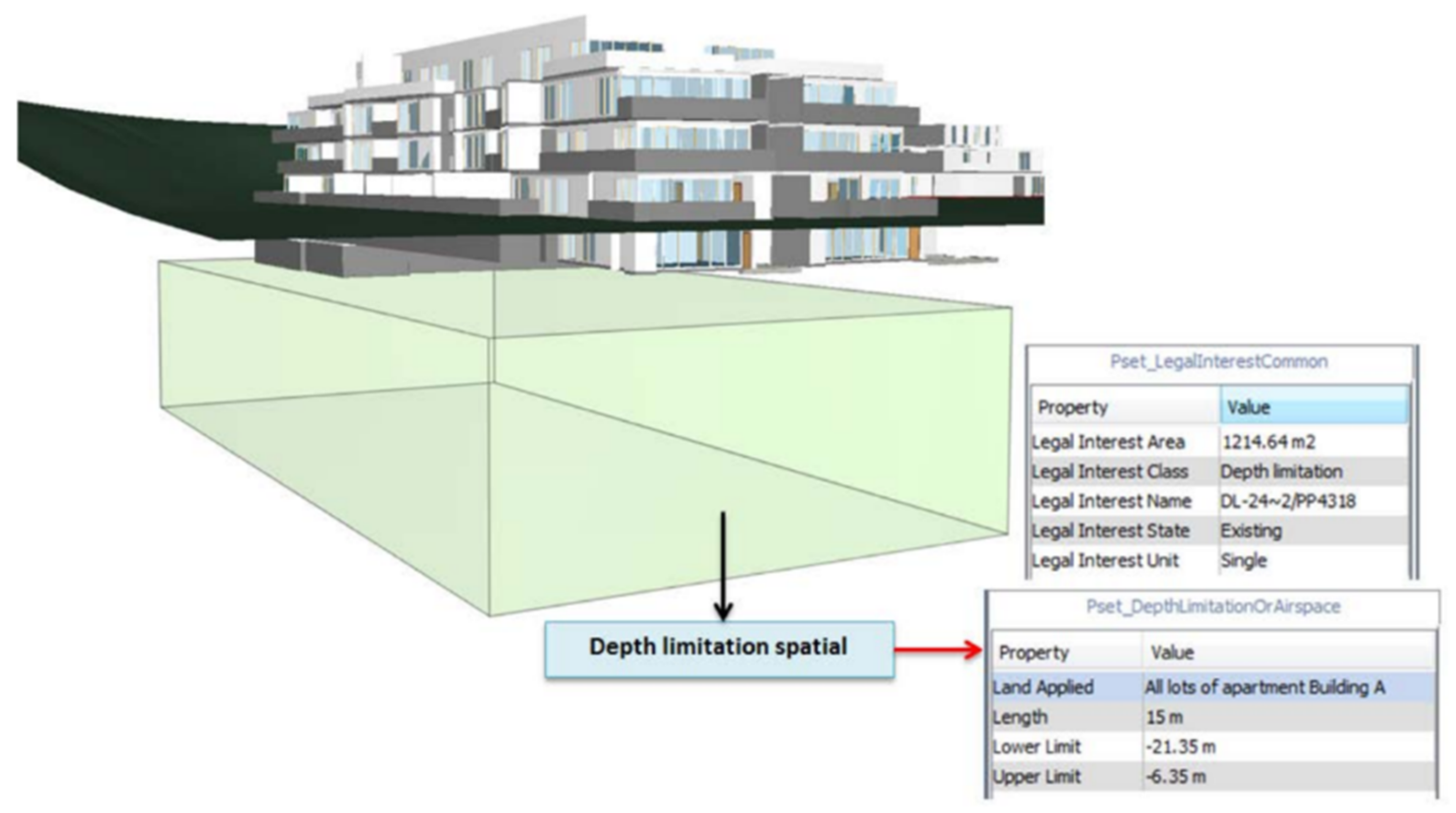
The volumetric ownership spaces in a multistorey building are divided into two types of ownership: private ownership and common property areas. Private ownership and common property are the two common and widespread form of ownership in some regions, such as Australia, Canada, and South America. They are respectively known as the condominium ownership type and the condominium user right type in some parts of Europe, such as Denmark, Germany and Sweden [37]. The private ownership includes apartment units (lots), car parks and storage areas. The internal walls inside the units are usually included in the definition of private ownership. The same applies to the walls within the common property areas. The internal walls are those that do not separate the ownerships; although they are structurally essential, they are not considered as ownership boundaries for private properties or common property areas. The ownership boundaries are those separating different ownerships. Corridors, elevators, stair areas, and other communal areas, as well as physical structures such as walls, ceilings, slabs and columns, can be part of common property areas. Some communal building service elements such as pipes, conduits, electrical wires, internal service ducts, and pipe shafts can be typically maintained through physical structures [9]. Defining walls as common property depends on the type of boundary. For example, for two adjoining lots with interior boundaries, the wall separating the lots must be part of common properties and needs to be defined so. One of the most important principles in defining the horizontal and vertical boundaries of volumetric ownership spaces inside the building is followed by preventing gaps or overlaps in the whole legal spaces defined. Some of the semantic information represented as notation on the plan now benefits the 3D geometry representation in the digital environment of BIM, such as depth limitation [25]. Depth limitation is a type of restriction that originates from the original crown grant [38]. The spatial extent of this legal interest is not delineated in subdivision plans and only its length is notated. For example, in Victoria, the maximum extent of ownership in some cases is 15.24 m below the surface. The spatial extent of depth limitation can be determined by underground volumetric spaces external to the building (Figure 3).
Stage 3: Each BIM platform utilises a proprietary format for storing BIM models [39]. The Industry Foundation Classes (IFC) is an open, neutral platform file format not controlled by any individual BIM vendor [40]. Therefore, the enriched BIM model with cadastral information is exported to the IFC data format. The IFC standard is object-oriented and uses a hierarchical spatial data model to manage building objects with a geometric representation or spatial extent. ‘IfcSpatialStructureElement’ is the abstract superclass for entities defining internal space (IfcSpace) objects. In the extended IFC model, the volumetric ownership spaces including private ownerships and common properties are represented as IfcSpace objects. ‘IfcElement’ is the abstract superclass for entities modelling physically existence objects. ‘IfcBuildingElement’ defines the architectural structure of the buildings including wall, column, window, slab, door and so on. A wide range of geometry representation methods embedded in BIM and IFC, including parametric modelling, Boundary Representation and Constructive Solid Geometry, make it possible to encode many types of geometries. This high level of complexity can, however, have consequences on interoperability and the way different pieces of software read and re-export the same geometry. This could be challenging in ensuring consistency in the use of the model, including conversion to and from other formats [41]. The exported IFC data model contains cadastral information including geometrical and semantical information. The transformation stage is the final step of developing a BIM-based cadastral data model.
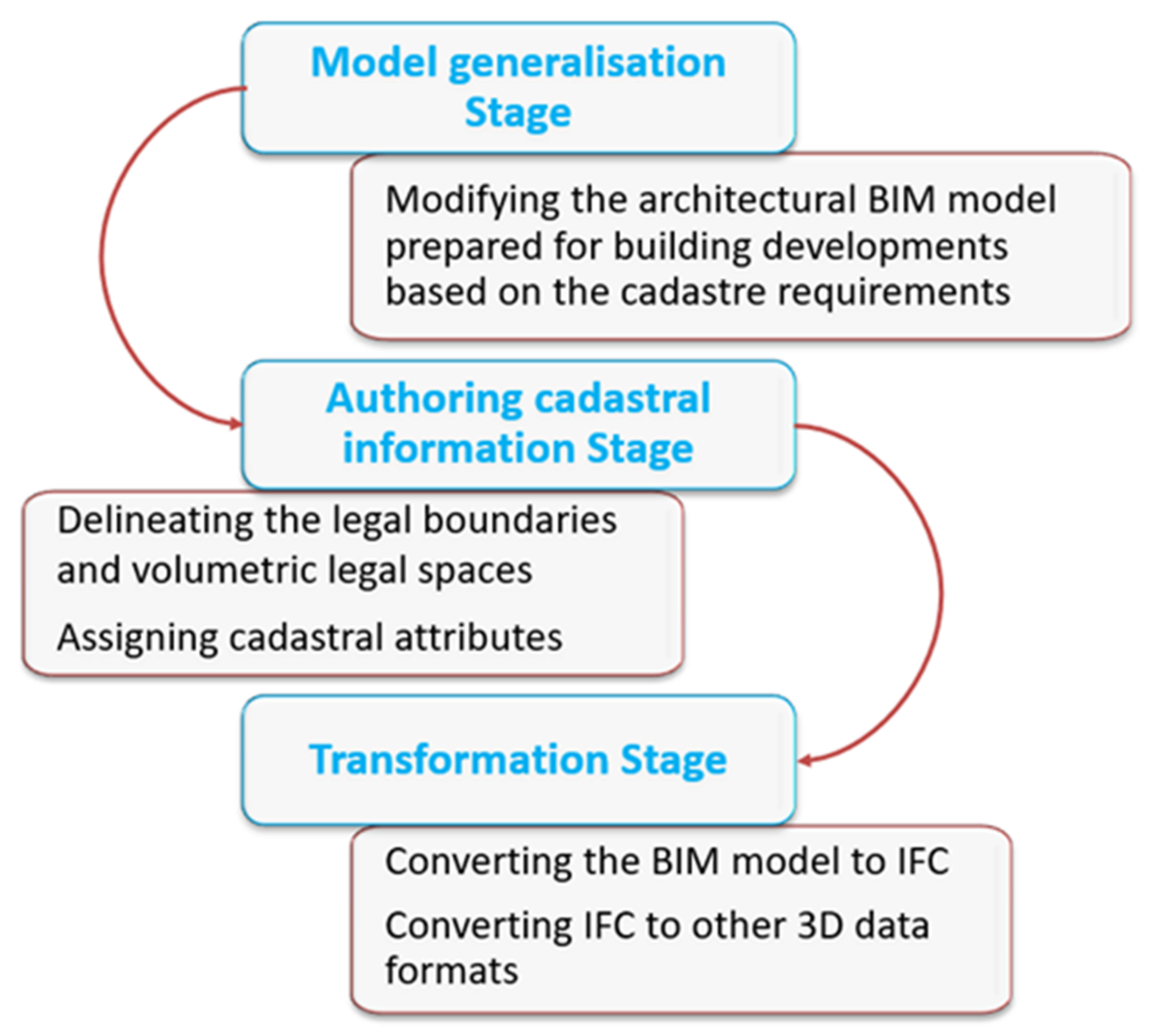
Three developed stages for generating BIM-based cadastral data are represented in Figure 4. It is worth noting that the developed stages are referred to as a new building’s design and development. However, these stages can be considered one step back when different methods are used for data capturing for the existing buildings.
3.2. Issues and Challenges
The process of generating BIM-based cadastral data seems to be a challenging and error-prone process. Investigating a case study, we identified common errors and issues at different stages within the process. In the following subsection, we identify the type and nature of errors and briefly explain why each error occurs and where they belong. This part of the study is essential to formulate and develop the assessment approaches, including the criteria and standards for each stage, which are discussed later in Section 3.3.
3.2.1. Model Generalisation Stage
The issues and challenges occurring in the BIM model may stem from architects’ de-sign approaches and the introduction of errors due to incorrect modelling of the building elements. The derivation of these issues may cause a domino effect on authoring cadastral information.
- Diverse design approaches
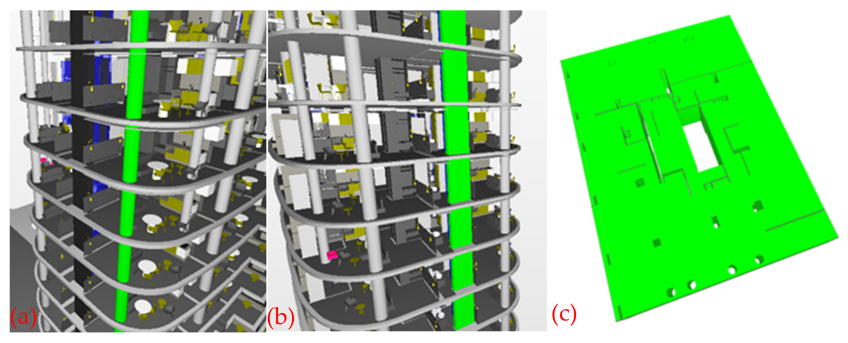
One of the design phase challenges occurs when some building elements such as shear walls or columns need to be designed, and there might be several design options for these elements. For example, when the walls, shear walls or columns inside each apartment unit are floor-specific, the base and top constraints will only span one floor, e.g., ground to floor 1, or floor 1 to floor 2. Alternatively, for spanning or multistorey walls, the base and top constraint of these elements might differ, and they may span the entire building. The geometry representation of lot or slabs is a non-simple polyhedron with several holes if the columns (Figure 5a) or shear walls (Figure 5b) span the entire building and go through the slabs or lots (Figure 5c). Spanning or multistorey walls may not properly bound upper storey spaces when exported to IFC. In the case of curtain walls, storefronts, and large windows, if the window is modelled as a multistorey object, it will not be properly related to a wall and will be an “orphaned” or “floating” object. Such windows will not have the correct bounding relationship to the adjacent spaces, which can cause errors and unexpected analysis results.
The design method is also dependent on whether a common property or private ownership is defined. For example, if the slab is part of common property areas it can be defined as one object and there is no need for it to be separately defined for each unit (Figure 6).
- Incorrect modelling and hard clash occurrence
Modelers might also introduce errors due to incorrect modelling of the objects. For example, the modeler may not notice that a wall is touching the slab, the ceiling, or another adjoining wall correctly [42]. If the joints between walls and slabs are missing in some BIM-authoring software, space may not be properly bounded. This can result in a problem when defining the ownership spaces.
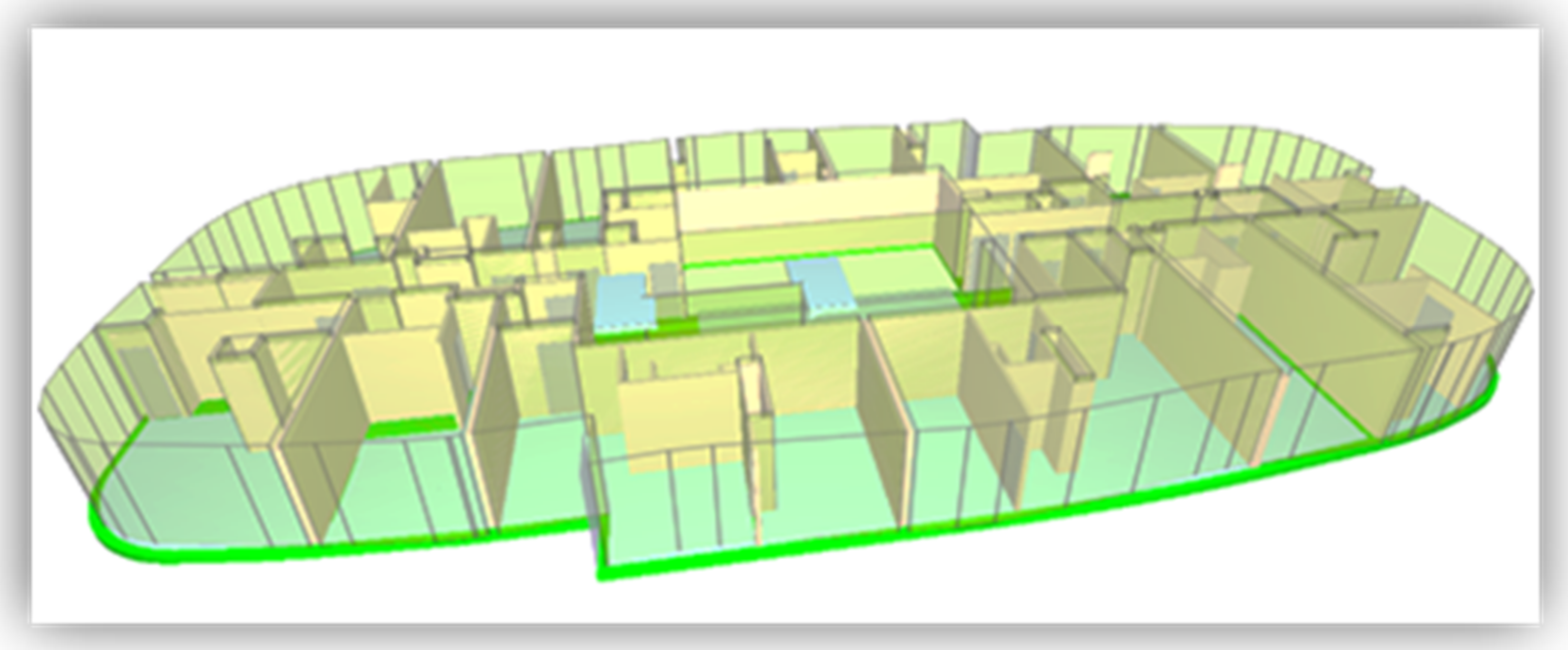
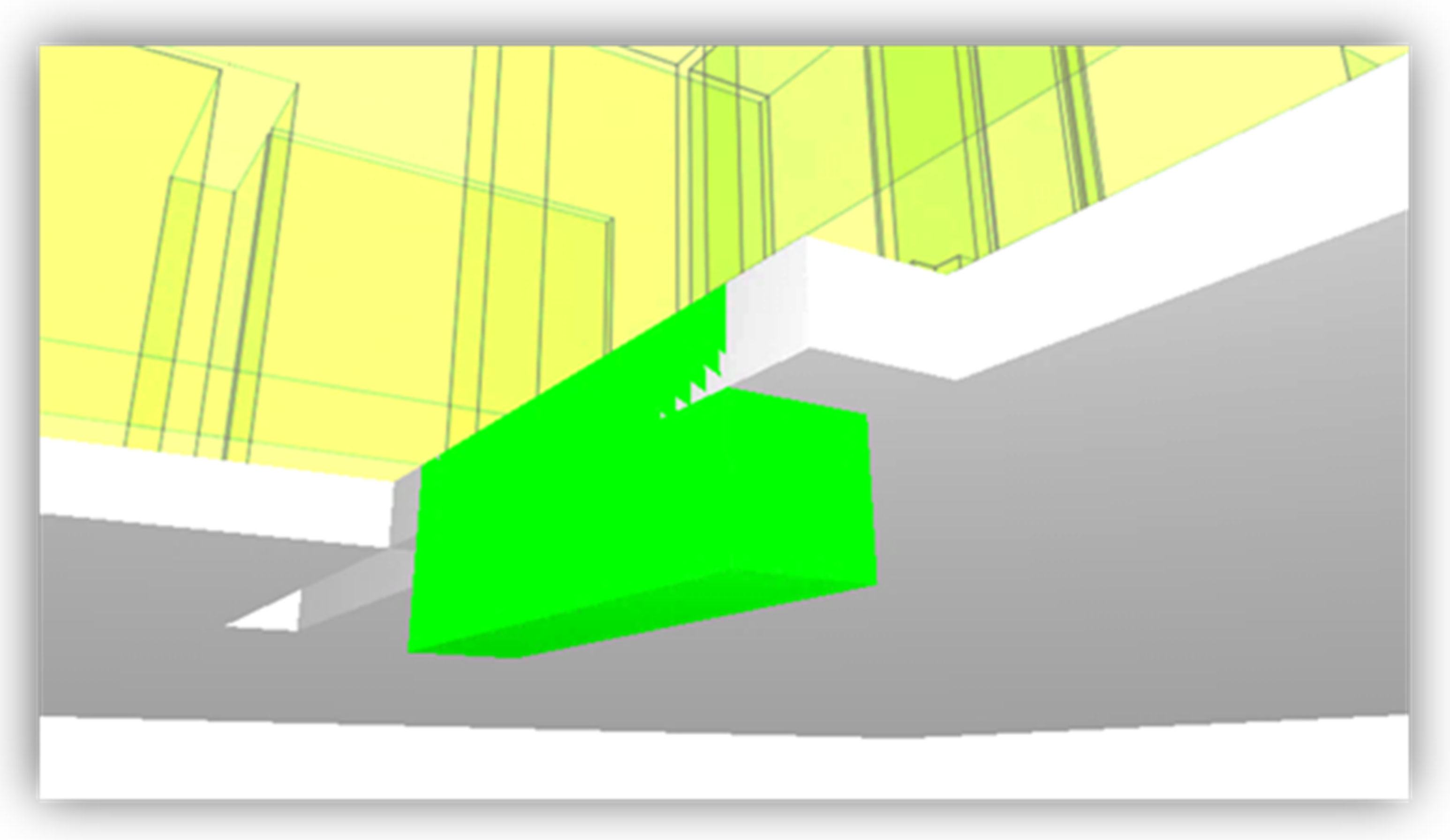
Another issue is associated with hard clashes occurring within the BIM model. A hard clash is a type of conflict which involves geometrical issues and occurs when two objects pass through each other or take up the same space (Figure 7). There is also a rarer type of hard clash concerned with duplicates, where the modeler puts two of the same objects in one place. Duplicate components may prevent defining the correct spatial extent of ownership boundaries. Figure 8 illustrates a duplicated floor system, which blocks extending the legal spaces to the living room or bathroom. Advanced modelling software will usually highlight the occurrence of duplicate objects. The undetected error might lead to significant inaccuracies while authoring the legal boundaries.
- Excess geometrical information
One of the issues regarding the architectural model is excess of data. For modelling the spatial extent of volumetric ownership spaces in a building, not all the physical elements located within apartment units such as furniture—highlighted with a green dash in Figure 8—are utilised [16]. This overabundance of geometrical information would increase the BIM model’s data volume, diminishing the speed of visualising, validating, and querying the model.
3.2.2. Authoring Cadastral Information Stage
There might be some issues and challenges while defining the legal boundaries and volumetric legal spaces in a multistorey building. Some of the main issues are discussed as follows:
- Undefined ownership space
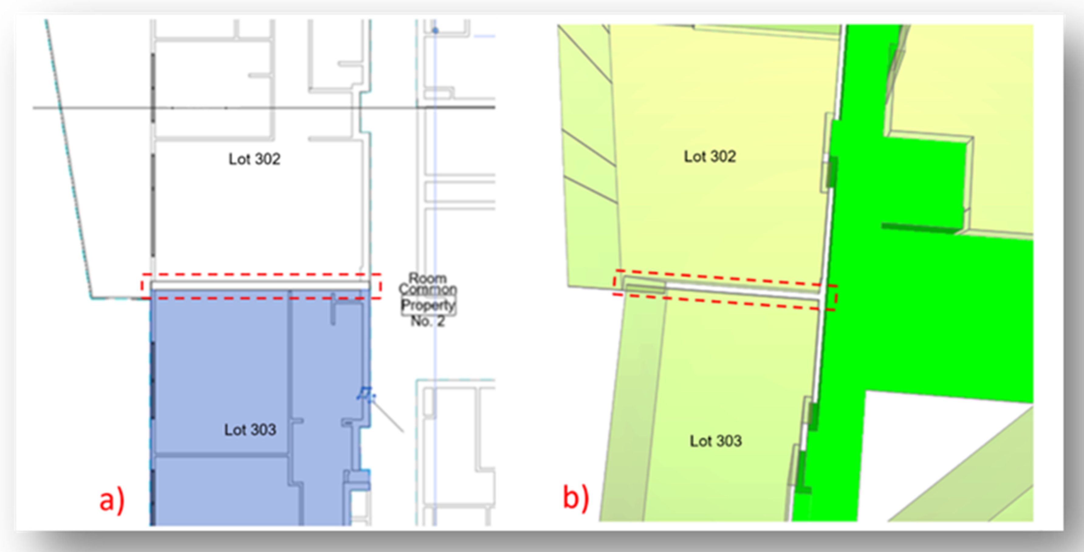
Undefined ownership spaces are sometimes found within a multistorey building, causing a gap among the stratified ownership spaces. In Figure 9, the type of boundaries for lot 302 and 303 are both interior. In this case, the wall between lots must be legally defined as a common property space. However, due to limitations in authoring methods, it is not always easy and possible to model this kind of situation. Therefore, when a wall is not legally defined within the authoring BIM software (Figure 9a), a gap among the stratified ownership spaces will emerge. Consequently, some of the IfcSpaces will be missed when the BIM model is converted to IFC (Figure 9b). However, the semantic information can help to assign such physical elements as common property and their geometry can be used for further analysis.
- Inaccurate or incorrect ownership space definition
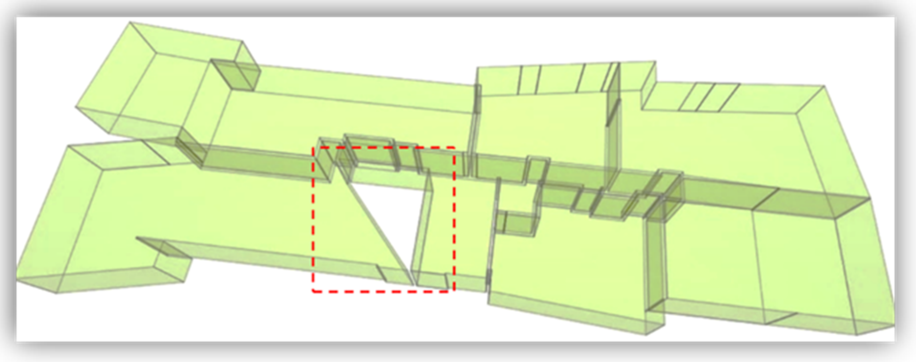
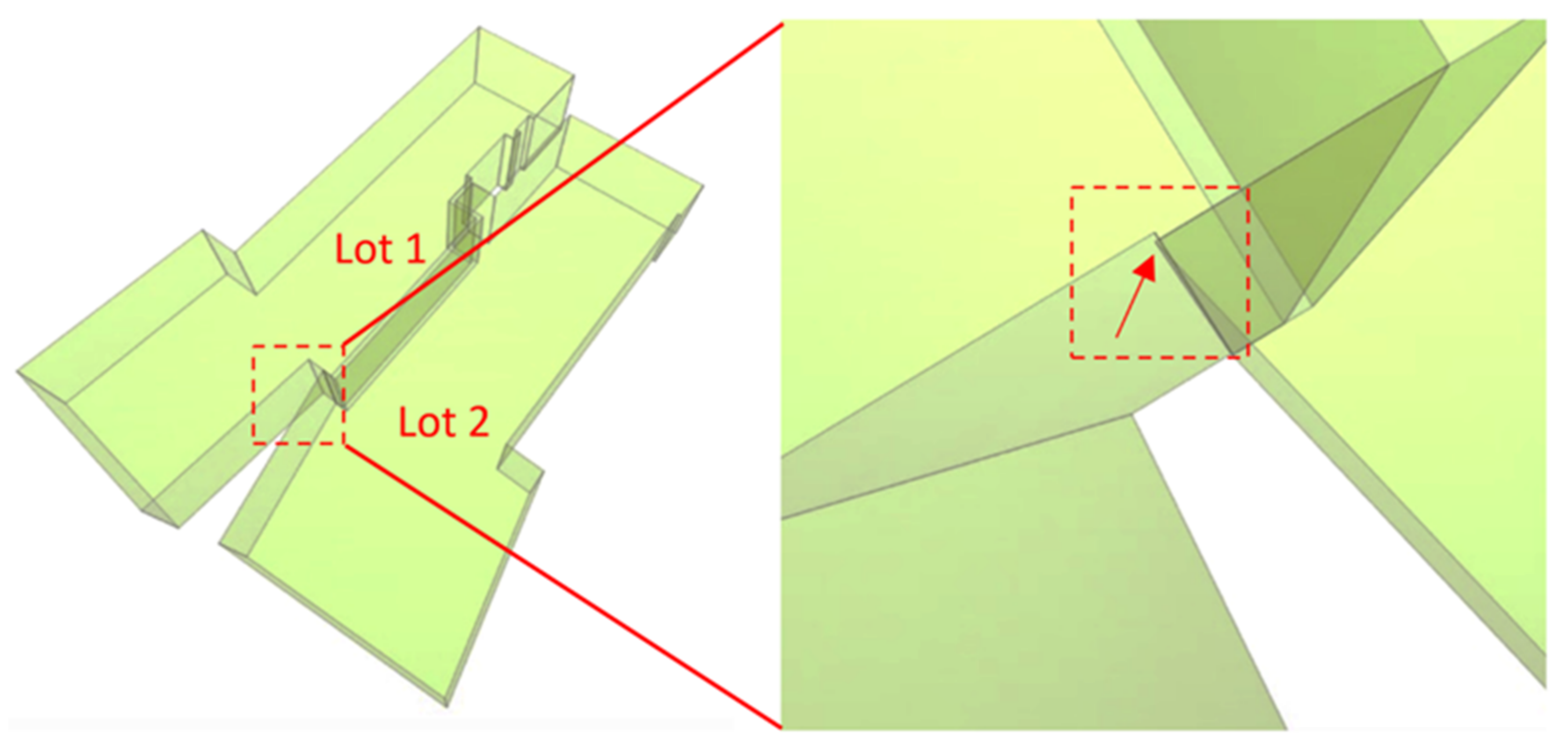
Another issue relates to the spatial extent of ownership. For example, when the lower and upper limit of a property is not correctly defined, the volumetric legal space will not represent the correct and accurate spatial extent of the ownership. Figure 10 illustrates a situation in which a gap is created due to an incorrect ownership definition. This type of error occurs while modelling the volumetric ownership space boundaries. The situation also threatens the internal and external spatial consistency of legal spaces within a building [25].
- Double defined ownership space
3.2.3. Transformation Stage
Some issues might be seen while converting the enriched BIM model with cadastral information to IFC entities. Besides the well-known computer’s floating precision issue, which may influence conversion, errors can also originate from the authoring design software [42].
- Errors generated by design software
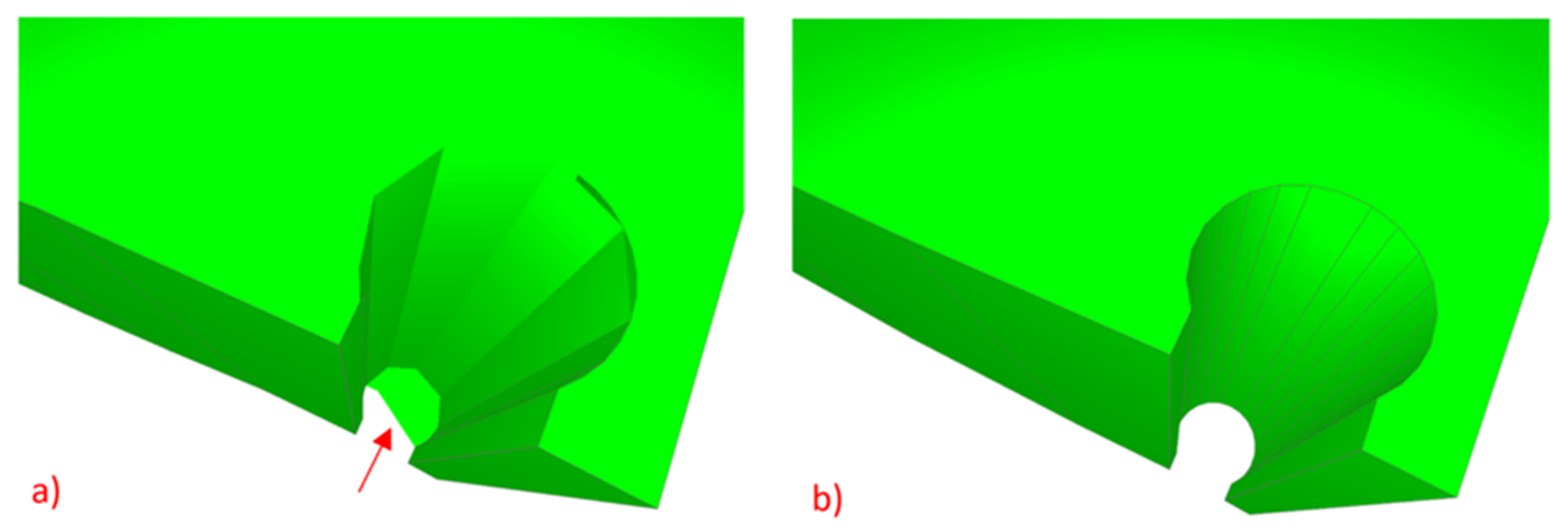
Figure 12 illustrates two IfcSpaces exported from a BIM model. The exported IfcSpace in Figure 12a represents an invalid IfcSpace as there is a dangling face at the bottom of a column and holes around the curved parts. Due to a lack of tools in the authoring BIM software, the model’s correctness may not be checked, and thus the modeller is not supported in creating models based on the standards.
- Geometrical information redundancy
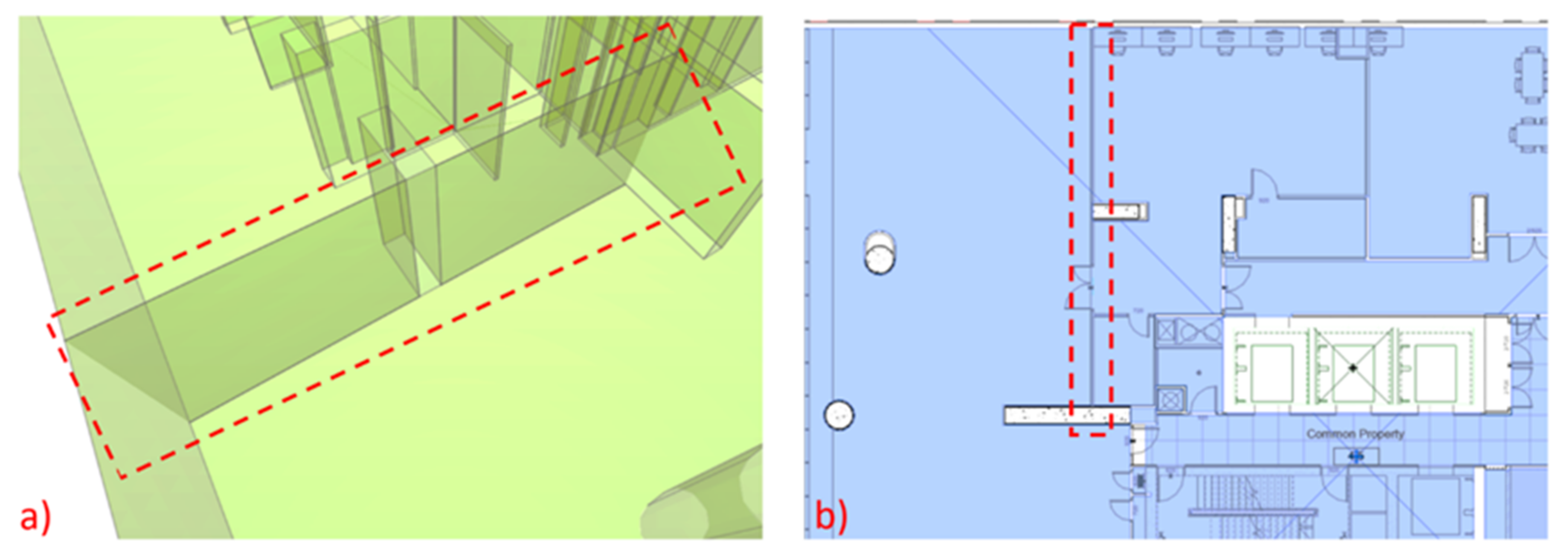
Redundant geometries are also seen in an exported IFC. In Figure 13a, a face was generated in the exported IfcSpace. In the BIM model (Figure 13b), the wall shown with red dash line is included in the lot ownership space as it is an internal wall within the lot. This error is not relevant to the modelling and the only reason for it might be the background algorithms used in the software during BIM to IFC export.
- Geometrical information missing
IFC data can be transformed into other 3D data formats. While the IFC data might be valid, transforming this data to another 3D data format may yield severe errors. Figure 14 illustrates an example of exporting IFC to OBJ format. OBJ is a geometry definition file format first developed by Wavefront Technologies. While the IfcSpace in Figure 14a is a valid watertight (closed) object, the exported OBJ object (Figure 14b) has missing top and bottom faces. This transformation made the OBJ file an invalid nonwatertight object. The reason for the manipulation of the data during the transformation is unknown.
Investigating different datasets reveals that generating a BIM-based cadastral model is error-prone in every stage. An error in the final outputs that was caused by an early-stage mistake cannot be easily traced. While validating the final cadastral data, such as an extended IFC, can identify the errors, it is imperative to have a multistep validation approach in every stage of generating the cadastral model. The next subsection introduces an integrated approach to validating the cadastral model.
3.3. Formative and Summative Assessments
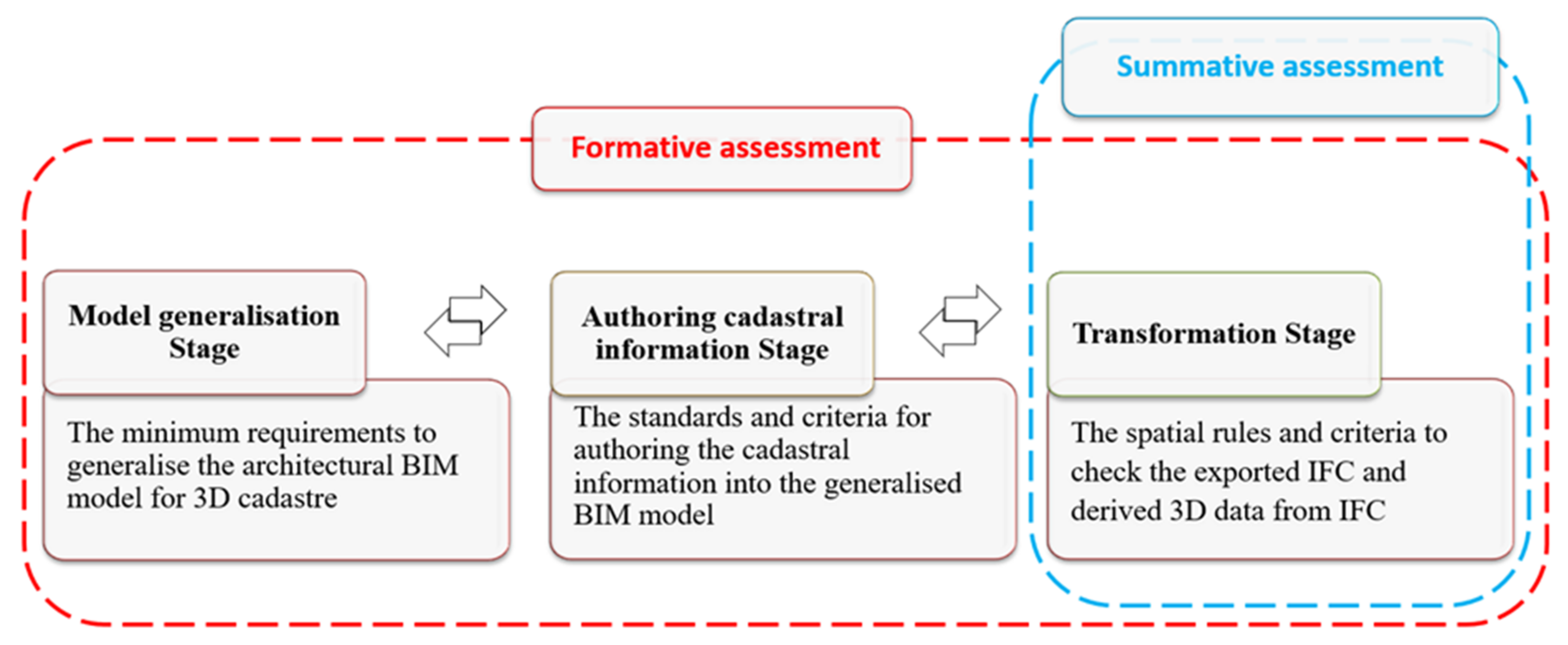
The process of data validation assesses data quality characteristics, including consistency, integrity, completeness, and correctness [43]. Formative and summative assessment are two known educational functions of assessment (of and for learning) [44,45]. These educational concepts were adopted to develop two quality assessment approaches, namely formative and summative assessment, to check the spatial consistency and integrity of cadastral data. Summative assessment is an approach that involves principles and validation rules to check the spatial consistency and integrity of the geometry of IFC entities and derived 3D formats from IFC. The output of this assessment includes a Boolean expression for each principle checking the geometrical validity of data. Summative assessment is meant to check the final outcomes instead of looking at a cadastral data model’s development at a particular point in time. This approach is also considered a “One-step data validation”. Compared to summative assessment, formative assessment is used in the ongoing modelling and within the process of data generation. In the formative assessment as a “multistep data validation approach”, the spatial consistency is checked during cadastral data generation in several stages. Formative assessment aims to monitor the quality of the data generation process by checking some criteria, principles, and standards at each stage. Formative assessment and summative assessment are two complementary approaches that can be used to check the cadastral data model’s spatial consistency and integrity.
The formative and summative data quality assessment in this study is formulated as below (Figure 15).
3.3.1. Minimum Requirements to Generalise Architectural BIM Model
Architects design the BIM model with several layers of information and details at an early development stage. A BIM author, modeler, or surveyor with BIM knowledge, however, can modify the BIM model for use in the land administration domain. The criteria developed here provide minimum requirements for checking the BIM model and modifying it accordingly before authoring the cadastral information.
Title boundary: The design of the whole building elements and components should be limited to the legal boundary of the land in which the development can occur.
The level of required information details: It is important to know that not all the building elements inside a building, such as furniture, are necessary from the legal perspective. The main building elements required for generalising the BIM model are walls, floors, ceilings, doors, and columns. Therefore, it is important to remove all the pieces of furniture within the apartment unit. The internal walls within the lots or common property areas can also be removed at this stage. However, the boundary walls separating different lots, lots and common properties, and different common properties, must remain unchanged.
Model’s coordinate reference system and height datum: To ensure all design models can be easily and readily cross-examined, design teams should reference the same coordinates for X, Y, Z, base point, survey point, Australian Height Datum and Angle to True North.
Checking the hard clash (overlapped or doubled building elements): The different building components’ geometry must not take up the same space. Models must be coordinated to eliminate object overlap or duplicate objects on top of each other. Conversely, it is just as important to identify where there is a gap between objects/elements.
Avoiding gaps or overlaps between spaces without bounding elements: In several cases, two adjoining spaces are not separated by a physical element such as a wall, partition, floor, or ceiling. This situation is very common where the car park boundaries are modelled in multistorey buildings. Any gaps or overlaps (horizontally or vertically) between these spaces need to be checked while modelling these spaces. The legal spaces within a multistorey building must be defined and modelled with no overlaps or gaps.
Checking the walls’ base reference: To properly bound a space, the walls encompassing a space, including curtain walls, must have the same base reference, such as a slab or level. Walls or columns should preferably be modelled separately for each building floor. Spanning or multistorey walls may not properly bound upper storey spaces when exported to IFC. Some BIM-authoring applications such as Autodesk Revit have a setting to split walls by storey when exporting to IFC, which should be selected if the model contains spanning or multistorey walls.
The slabs’ design: Slabs must be properly joined to walls and enclose spaces to ensure model integrity. For model consistency, it is essential that the floors are modelled as slab objects and that the joints between walls and slabs are modelled as accurately as possible.
Checking the design of the multistorey spaces: The spaces spanning higher than one storey are called multistorey spaces. Such spaces can be defined for a lift spanning multiple stories, for instance. Multistorey spaces must be modelled as one space per floor. However, a modeler needs to make sure there are no gaps, overlaps or misplacements in the vertical direction between these spaces, so that the total volume and the whole object remains accurate. For example, spaces in the upper floors should be given a base elevation equal to the top of the space below, not starting at the next floor.
Modelling balconies and terraces as spaces: The covered balconies within the building and terraces for single or multi-occupant use should be modelled as spaces. Their height should be bounded by the ceilings or other surface above. If there is no surface above, the height should be set equal to adjacent space heights in the same building floor. The space above balustrades in the balcony sometimes needs to be defined as common property, and different authoring software might handle this situation differently.
3.3.2. Criteria and Standards for Authoring the Cadastral Information
While the BIM data environment could provide the geometry for 3D cadastre, the spaces themselves may be different from those defined by the BIM. The legal space in BIM-based cadastral data should be defined as only one space for a single property. This is despite the space including some physical spaces (rooms) or parts of physical spaces (walls) [18]. The criteria developed in this subsection needs to be checked while authoring the cadastral information.
Type of boundary definition: Four types of boundaries including interior, median, exterior and some other locations must be differentiated when legal boundaries are defined by referring to a building or part of a building [46].
Undefined or duplicated defined ownership space: There is one fundamental principle that must be considered while defining the horizontal and vertical legal boundaries and volumetric legal spaces: any gap and/or overlap in the whole stratified ownership spaces in a multistorey building should be avoided. In the case of authoring BIM limitation on defining such legal space, semantic information must be assigned to the physical element.
Checking the ownership definition integration for every single property as one space: While BIMs work with complex physical objects, for example, the rooms, corridors, walls, and floors of a building, the legal space needs to be defined as only one space for a single property. As a result, all the internal walls separating rooms inside a single property are part of that property’s legal space. In authoring BIM software, the interior face of a wall, column or slab is used as default for delineating legal boundaries. However, for defining any other type of boundaries, such as a median, other methods need to be used. For example, in Revit the default method for defining an interior boundary is by using the ‘Room Bounding’ attribute, and for the exterior or median boundary the ‘Space Separator’ tool is used. Therefore, the room bounding tick should be removed while defining these elements inside a single property.
Checking common property definition as one object: A spanning shear wall or column can be defined as floor-specific or as one object spanning the entire high-rise building. Regardless of designing these objects, it is expected when, for example, common property #1 is selected, the whole object is presented as one legal object.
Checking the accessibility of each lot to the outside through common properties: Any privately owned or occupied lot must be connected to space outside through the common property areas to get accessibility. Besides, any common property areas cannot be completely enclosed by a private parcel (lot) [3].
Upper and lower boundaries of defined ownership spaces: Once the legal boundaries are defined horizontally, volumetric legal spaces for private and common properties must be defined vertically. Therefore, their upper and lower boundaries must be defined based on the location of the boundaries within the floor and ceiling.
The homogeneity of zoned ownership spaces: All ownership spaces belonging to one specific private or communal ownership right should be zoned. For example, the ownership space for Lot #100 in floor 1, ownership space for Parking #100 in basement #02, and the ownership space for Storage #100 in basement #02 can be added to a zone named ‘Lot 100’. Likewise, the same concept can be used for categorizing common properties.
The correctness of semantic information: Authoring BIM software such as Revit provides a predefined set of parameters (attributes) for any building components such as walls, doors, windows, spaces or zones, which are mainly for architectural and engineering purposes. However, a mechanism can facilitate adding semantic information such as RRRs and owner information (e.g., lot liability, lot entitlement, land use, common property type) to the BIM model. The cadastral attributes can be assigned into the zones, and the values can be edited. The cadastral attributes can also be populated automatically from Excel files using Dynamo BIM visual programming language.
3.3.3. Checking the Spatial Consistency of Exported Data in the Transformation Stage
The exported IFC entities need to go through a summative assessment to meet a set of requirements. As the main aim of the entire process is having a valid IFC output, the following principles provide a set of requirements that investigate the validity of the geometry of exported IFC data or derived 3D data from IFC.
Checking for empty geometries: It can sometimes be seen that an exported IfcSpace does not include any information regarding the geometry of the entity. An empty geometry is a geometry value that has no points. This principle checks a basic rule regarding the geometry to ensure a geometry is aligned for each legal space or physical element in a multistorey building.
Point duplications: This principle aims to check the existence of any point duplication in the exported data geometry.
Self-Intersection: This principle checks any self-touching in the exported data geometry faces, such as an IfcSpace.
Checking nonplanar surface: A nonplanar face or surface part does not have all its vertices on the same plane in 3D space. Therefore, this rule checks if each face of the geometry is planar.
Checking surface orientation: This rule assures that there are no flipped faces on the surface of an exported data’s geometry.
Checking solid orientation: IFC entities are represented as Solid Models. A solids’ orientation determines the inside and outside of that solid. If the normal vectors of outer shells do not face out or the normal vectors of inner shells do not face in, the orientation is considered invalid. The orientation is also invalid if the orientations of all IFC entities are not consistent.
Checking valid solid boundaries: An IFC object or other exported data from IFC represents a watertight, non self-intersected and properly oriented object if this criterion is passed.
Checking invalid solid voids: A void is a cavity, or an empty region within a solid, and is defined by an inner boundary. A solid is defined by an outer shell and one or more inner shells. This validation rule can detect duplicate shells, shells that intersect, and if the interior of the shell is not connected.
4. Implementation and Result
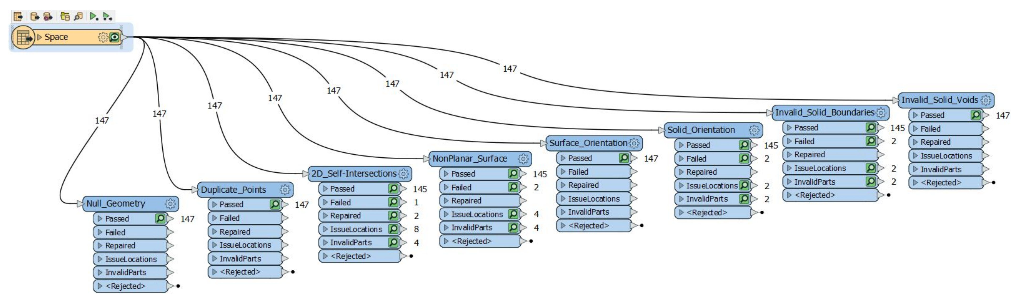
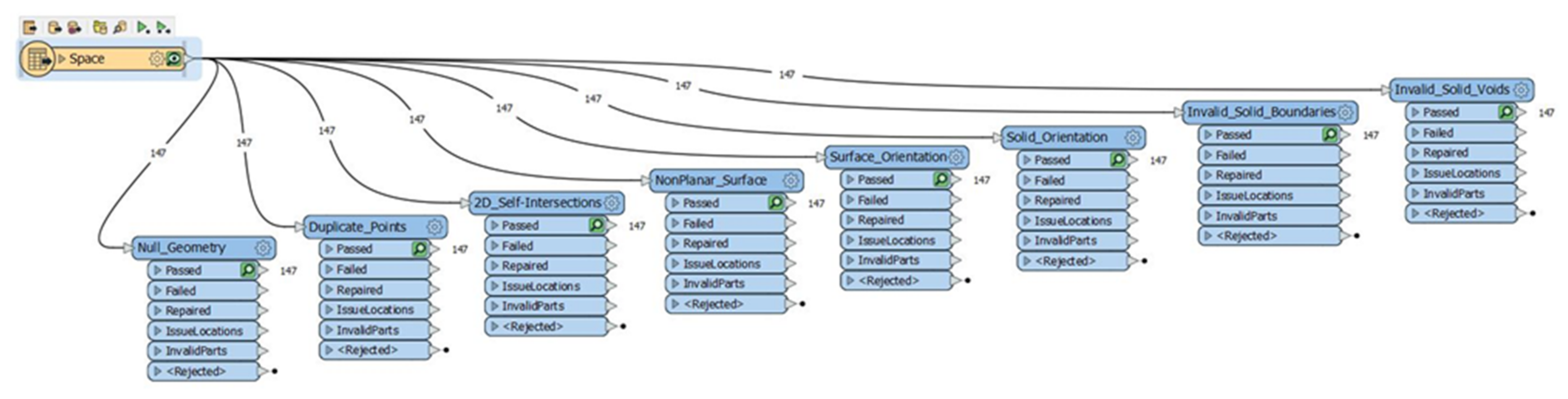
A real cadastral dataset was checked using summative and formative assessments. As a case study for the implementation, a four-floor building was selected in Victoria, Australia. This building’s cadastral data model was created using an architectural plan through the developed stages in Section 3.1. The Feature Manipulation Engine (FME) Desktop was employed for summative quality assessment. FME® Desktop software has strong support for 3D geospatial data manipulation. Several standard formats such as CityGML, IndoorGML and IFC, and other 3D data file formats like OBJ, STL and COLLADA are supported. FME GeometryValidator was used to check the exported data’s geometry from the enriched BIM model against the criteria proposed in the summative assessment. The input IFC data model was imported and decomposed in FME, allowing the selection of individual IFC entities. We limited the selection of entities to IfcSpace. The IfcSpace in our dataset represented the legal spaces, including private ownerships (lots) and common properties and contained 147 IfcSpace entities (Figure 16).
4.1. Evaluating the IFC Data Using Summative Assessment
The exported IFC files were checked against the criteria developed in the transformation stage including checking for empty geometry, point duplication, self-intersection, nonplanarity, solid orientation, and invalid solid boundaries, and so on. Only two IfcSpace entities failed, passing some of the validation rules listed in the summative assessment approach (Figure 17).
The result of the summative assessment solely provided Boolean expressions of the validity status of the exported IfcSpaces (i.e., a pass/fail or valid/invalid status). The FME data inspector helped to visualise the errors. However, this was the only information provided by GeometryValidator and to investigate the source of the errors, analyse and interpret them, the model was manually checked against the criteria and standards provided by formative assessment to complete the data validation process.
4.2. Evaluating the BIM Data Using Formative Assessment
Formative assessment provides criteria and standards for improving the BIM model for cadastre while generating data. Since the BIM-based cadastral data generation is done manually, the formative assessment is also currently a manual process.
The two invalid objects are exaggeratedly shown and zoomed in on Figure 18. In the first case (Figure 18a), a face makes an IfcSpace non-2-manifold and disconnected. Non-2-manifold objects are allowed in cadastre if the connectivity of a single property parcel’s whole legal space is preserved [21,26,47]. This redundant face has also caused a self-intersection problem on the surface of the IfcSpace and makes the IfcSpace non-orientable. This object represents a legal space as one common property; therefore, it is just one cadastral object with connected legal space and the face is possibly redundant. The second invalid case shown in a zoomed mode in Figure 18b is relevant to common property and is the result of the same situation; however, the error’s source is different.
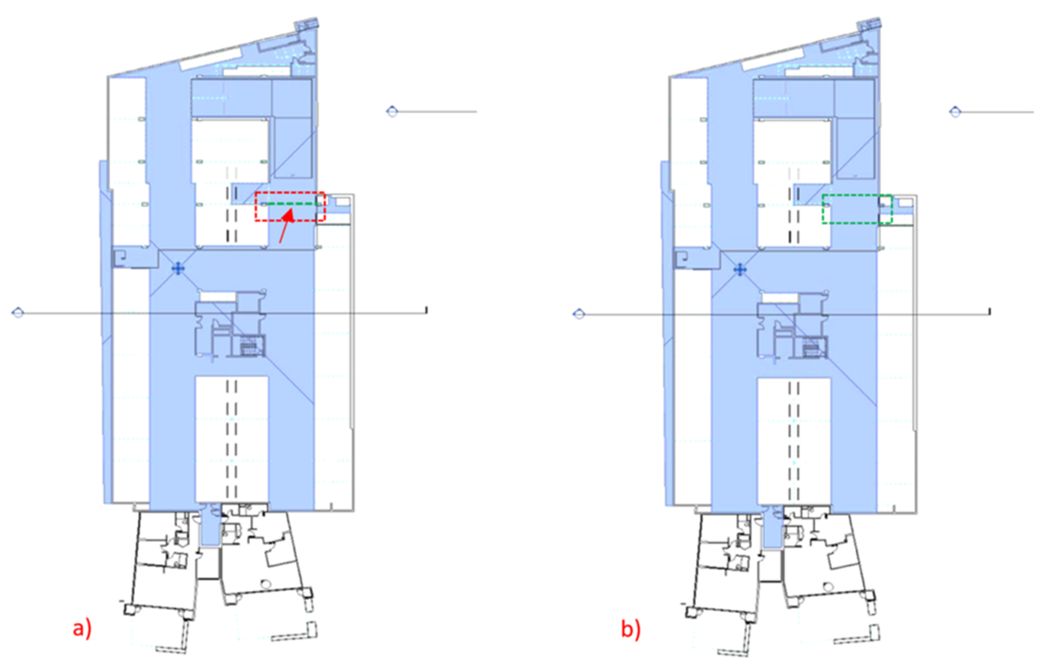
Through a formative assessment, the sources of errors in first and second objects were detected in the model generalisation and the authoring cadastral information stage, respectively. The first case suffered from a lack of correct horizontal legal extent definition in the authoring software. Using the separator in Revit is common where the median, exterior, or other location is used to define the legal boundaries. However, in the first case (Figure 18a), a redundant separator in the Revit file was desultorily used while authoring the cadastral information (Figure 19a). As one of the criteria developed in authoring the cadastral information stage, the horizontal extents need to be checked using a cadastral plan or a surveyor. As part of the formative assessment, the horizontal legal extent was checked and the redundant separator was removed in Revit (Figure 19b).
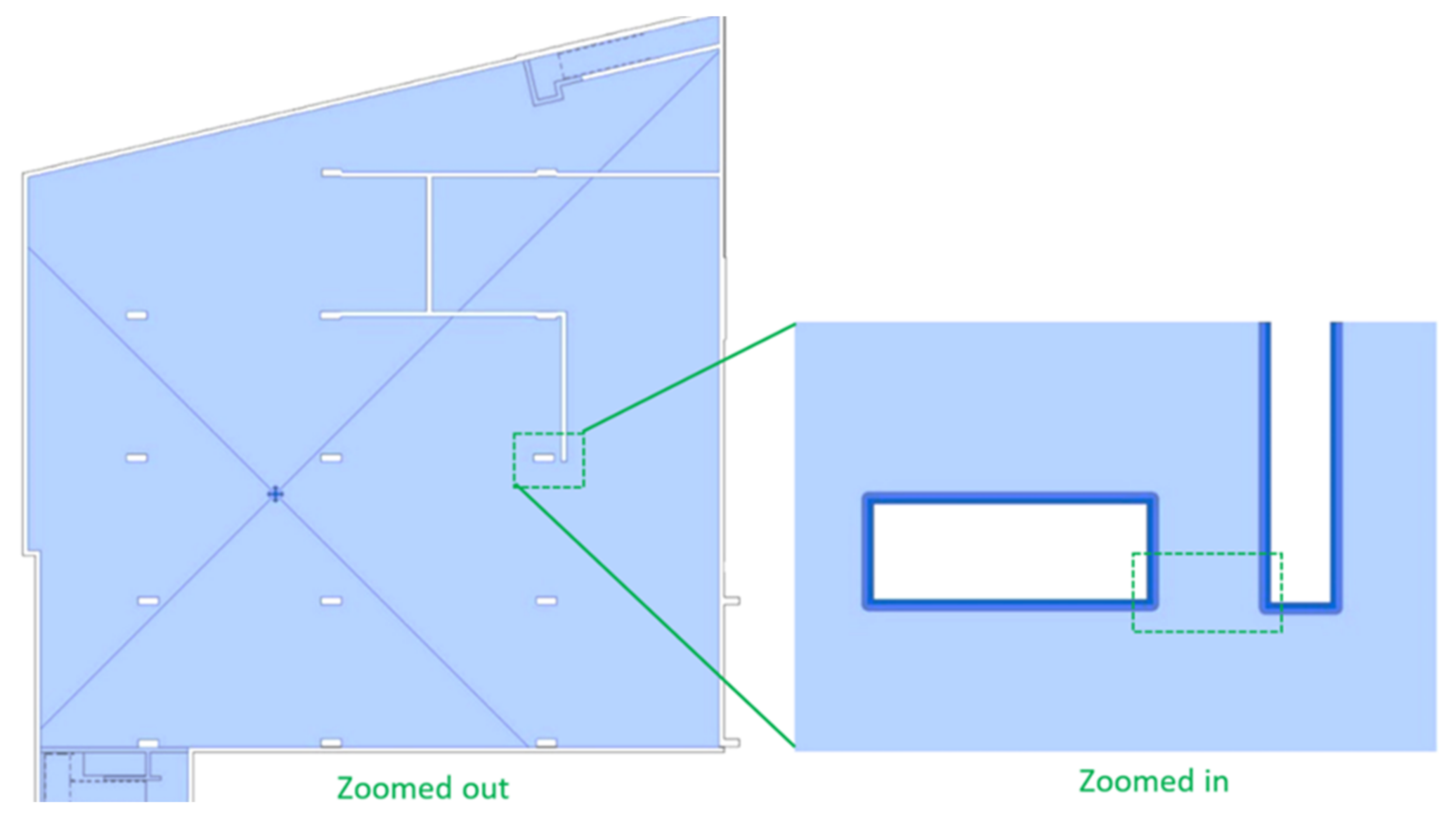
The problem’s source in the second case was found in the model generalisation and transformation stages. This error stemmed from a software error while defining the space boundaries. This sometimes happens where two geometries of two objects in 2D are very close to each other. In this case, a column was drawn close to a wall. As a result, the boundary of the column and wall were attached. When the software tried to define the space, some extra (redundant) lines were created connecting two geometries, like the area zoomed in and shown in the red rectangle in Figure 20. However, the geometries were not connected according to the architectural and cadastral plan.
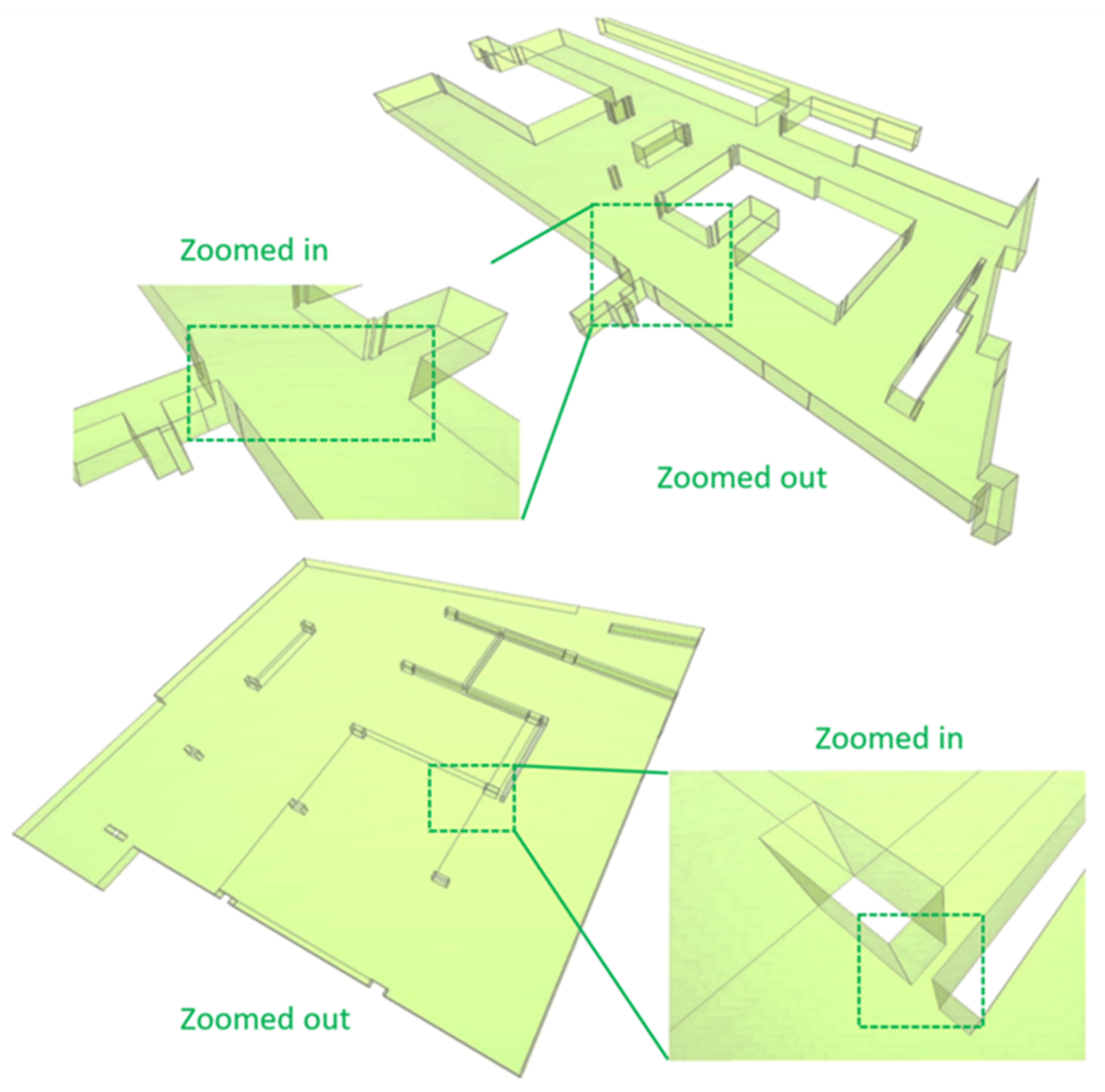
The source of this type of error is unknown and hidden in the export and conversion algorithms used by design software. However, to avoid this type of error, the elements designed in the BIM model need to be checked and redefined where possible (Figure 21).
The other problem that can occur here is when building elements and spaces terminate at points that are very close to each other and not connecting at the common points in 3D space as they should [48]. This error can be due to geometric tolerance and snapping.
4.3. Reevaluating the IFC Data after Implementing the Formative Assessment
Following the criteria for generalising the BIM model’s design and authoring the cadastral information can help avoid this type of error. After implementing the formative assessment on our BIM model, the refined version was exported to IFC (Figure 22) to re-examine through the criteria developed in summative assessment. The result did not represent any errors and passed all the validation rules (Figure 23).
The passed invalid solid boundaries per se certified that the IfcSpaces were all watertight, non-self-intersecting, and properly oriented. As shown in the FME GeometryValidator results, there was no null geometry, no duplication points, no nonplanar faces, or invalid voids in the improved IfcSpaces. The validation rules relevant to the orientation of the faces and solids were also passed. The implementation results confirm that subject to the existence of a native BIM file it is often best if both summative and formative assessments are complementary and used at separate times in the data generation process.
5. Discussion
The BIM model provides significant benefits regarding communicating complex ownership spaces within multistorey buildings [49]. Checking the validity of BIM-based cadastral data is a fundamental step to ensure the reliability and trustworthiness of the spatial extent of stratified ownerships defined in multistorey buildings. Developing a cadastral data model using the BIM model is a process that involves several stages, including model generalisation, authoring cadastral information, and transformation. However, the argument here is whether validation should only be one step applied to the final output or if it should be considered as a multistep process during data generation. In this study we developed a summative (one-step) approach alongside a formative (multistep) approach. The formative assessment was designed to investigate the minimum requirement of data quality in each stage. A summative assessment was also used to check the final exported data’s validity for possible geometrical errors.
The implementation’s result on a real cadastral dataset revealed that an exclusive summative assessment is not enough to guarantee the cadastral data model’s validity. Although a summative assessment provides a set of geometrical rules to check the validity of exported data, the results of this assessment did not provide much information about the sources of errors. Furthermore, through a summative assessment, only existing IFC entities are checked. However, we might not be able to trace the missing IFC entities and the sources of the errors. In other words, a summative assessment is necessary but not sufficient, especially when the cadastral data is generated throughout the process.
The summative assessment (one-step data validation approach) is recognised as a common approach in recent studies for checking the validity of final cadastral data. The focus of these studies has been on developing the criteria and validation rules to check the final cadastral data. This study revealed that data generation and validation are complementary and can be considered in parallel. One of the strengths of this study compared to previous studies [20,21,22,23,24,25,26,27] is that the cadastral data validation was viewed and considered as a process. This seems to make sense since the cadastral data generation is also a process. This makes more sense when BIM model are used for generating the final cadastral data. This enables modelers to check the spatial consistency and integrity of the model during the data generation process. Compared to the one-step data validation approach, a formative and summative assessment together can guarantee the spatial consistency, integrity, correctness, and completeness of cadastral data. A formative assessment provides criteria and standards for improving the BIM model for cadastre in different stages of data generation. It also helps to ensure the final exported IFC data, which are usually assessed by summative assessment, have less geometrical errors. We also showed that as generating BIM-based cadastral data is a process, it would be more efficient and reliable to check the validity of data during the process rather than at the end. It is also important to mention that the BIM-based cadastral data still needs to be checked after construction, as the registration can only be carried out after a construction has been built.
There is a trend towards modernising land administration systems. Automating the cadastral data generation, validation and registration are key foundations for modernising land administration. The finding of this study, including the methodology for data generation and criteria and standards for data validation, could underpin such automation to speed up and facilitate land administration modernisation. The developed criteria and standards can be utilised by various stakeholders, such as land surveyors, architects, and the land registry, to develop and validate cadastral data. However, the application of this research still relies on adopting BIM for 3D cadastres in land administration related policies and legislation.
An apparent limitation of this study is that the assessments were not fully automated. The result showed that an undefined legal space might be relevant to a wall; however, authoring the walls as legal spaces is not straightforward in authoring software and needs the development of new automatic methods. However, the criteria and standards proposed in this paper are essential to facilitate developing these automatic methods. The focus of this paper was on validating the geometry of legal spaces. However, physical objects can also be assessed through developed quality assessments. The semantic information can also be checked as part of the formative assessment. Autodesk Revit is one of the most well-known BIM authoring tools in the AEC industry for modelling complex developments among different design software [49]. However, other authoring software such as ArchiCAD, Tekla and Vectorworks, as well as Rhino 3D and Navisworks, can also be considered for modelling the volumetric ownership spaces in future studies. While most of the criteria and standards could be used and generalised to apply to other BIM authoring software, the tools used for applying them might be different. Some of the issues, particularly regarding BIM to IFC export, might also be handled differently in other software.
6. Conclusions
This paper aimed to investigate the process of generating cadastral data using the BIM model, the challenges and errors to be avoided in the process, and validation methods needed during and at the end of the process. Three main stages for generating the BIM-based cadastral data model were developed, and the issues and challenges within the process were discussed. As a result, two validation approaches, namely summative (i.e., one-step) and formative (i.e., multistep), were developed. Summative assessment is the method that assesses the validity of the final cadastral output. However, a formative approach can be used during the process of data generation. Both formative and summative assessments play vital roles in the process of enriching BIM-based cadastral data models and improving the quality of the final output.
This study revealed that reducing the IFC errors depends greatly on designing the building elements and modelling the legal boundaries within the BIM model. The method of designing and drawing the physical objects to generalise the BIM model for 3D cadastre can also affect authoring the cadastral information into the BIM model.
The validation approaches proposed in this paper provide requirements to increase the quality of the IFC data model enriched for 3D cadastre and drastically decrease the number of geometrical errors and ambiguity occurring in each stage. The process, however, can be automated in some stages, such as delineating the legal boundaries and modelling the volumetric ownership spaces. As there are no standards and guideline on how 3D BIM-based cadastral data can be generated and evaluated, the outcome of this study can help modelers and surveyors to generate such cadastral data. Depending on what kind of data will be used in registration (e.g., IFC or BIM model), the outcome of this study can also help examiners in land registry to check the internal and external spatial consistency of cadastral data, particularly with respect to checking the geometry of the final output.
According to the National BIM Report 2019, the most widely used BIM software is Autodesk Revit. However, for the future direction of this study, we will investigate other architectural model designs in other authoring software such as ArchiCAD, Vectorworks and Rhino 3D, and expand the requirements as open standards. It is important that future research investigates automatic processes of authoring legal boundaries and volumetric legal spaces, as well as detecting overlaps and gaps within authoring software. The methods for topological relationship analysis can also be developed to check the relationships among physical and legal objects. While providing the requirements and standards to BIM authors is necessary to avoid fewer errors in the final exported IFC file, it is recommended to develop research based on the use of IFC itself. The future research on this can facilitate developing new tools capable of solving errors in the IFC files itself and providing the requirements to BIM authors to make them independent of commonly used authoring software.
The outcome of this study provides insights into the potential of BIM as a data input for 3D cadastres. With the increasing adoption of BIM in architecture, engineering and construction, the insight facilitates the transition from 2D cadastres to 3D cadastres. Further, the study offers practical standards and guidance to use BIM for 3D digital cadastre. The finding will facilitate modelling and validating 3D RRRs in BIM for a 3D cadastre.
Author Contributions
Conceptualization, A.A.; methodology, A.A.; software, A.A.; validation, A.A.; formal analysis, A.A.; investigation, A.A.; resources, A.A.; data curation, A.A.; writing—original draft preparation, A.A.; writing—review and editing, A.A., M.K. and A.R.; visualization, A.A.; supervision, M.K. and A.R.; project administration, A.R.; funding acquisition, M.K. and A.R. All authors have read and agreed to the published version of the manuscript.
Funding
This research was funded by the Australian Research Council, grant number LP160100292.
Data Availability Statement
The sample data in OBJ format that could support the findings of this study are available in (https://github.com, accessed on 5 August 2021) with the identifier (https://github.com/aliiasgharii/Data, accessed on 5 August 2021).
Acknowledgments
The authors acknowledge the support of project partners: Land Use Victoria, Intergovernmental Committee on Surveying and Mapping (ICSM) and City of Melbourne. The authors emphasise that the views expressed in this paper are the authors’ alone.
Conflicts of Interest
The authors declare no conflict of interest. The funders had no role in the design of the study; in the collection, analyses, or interpretation of data; in the writing of the manuscript, or in the decision to publish the results.
References
- Shojaei, D.; Olfat, H.; Briffa, M.; Rajabifard, A. 3D digital cadastre journey in Victoria, Australia. ISPRS Ann. Photogramm. Remote. Sens. Spat. Inf. Sci. 2017, IV-4/W5, 117–123. [Google Scholar] [CrossRef] [Green Version]
- Gulliver, T.; Haanen, A.; Goodin, M. A 3D Digital Cadastre for New Zealand and the International Opportunity. ISPRS Int. J. Geo Inf. 2017, 6, 375. [Google Scholar] [CrossRef] [Green Version]
- Karki, S.; Thompson, R.; McDougall, K. Development of validation rules to support digital lodgement of 3D cadastral plans. Comput. Environ. Urban Syst. 2013, 40, 34–45. [Google Scholar] [CrossRef]
- Soon, K.H.; Tan, D.; Khoo, V. Initial Design to Develop a Cadastral System that Supports Digital Cadastre, 3D and Provenance for Singapore. In Proceedings of the 5th International FIG 3D Cadastre Workshop, Athens, Greece, 18–20 October 2016. [Google Scholar]
- Larsson, K.; Paasch, J.M.; Paulsson, J. Conversion of 2D Analogue Cadastral Boundary Plans into 3D Digital Information: Problems and challenges illustrated by a Swedish case. In Proceedings of the 6th International FIG 3D Cadastre Workshop, Delft, The Netherlands, 2–4 October 2018. [Google Scholar]
- Drobež, P.; Fras, M.K.; Ferlan, M.; Lisec, A. Transition from 2D to 3D real property cadastre: The case of the Slovenian cadastre. Comput. Environ. Urban Syst. 2017, 62, 125–135. [Google Scholar] [CrossRef]
- Guo, R.; Li, L.; He, B.; Luo, P.; Ying, S.; Zhao, Z.; Jiang, R. 3D cadastre in China: A case study in Shenzhen City. In Proceedings of the 2nd International Workshop on 3D Cadastres, Delft, The Netherlands, 16–18 November 2011; International Federation of Surveyors (FIG): Copenhagen, Denmark, 2011. [Google Scholar]
- Stoter, J.; Ploeger, H.; van Oosterom, P. 3D cadastre in the Netherlands: Developments and international applicability. Comput. Environ. Urban Syst. 2013, 40, 56–67. [Google Scholar] [CrossRef] [Green Version]
- Rajabifard, A.; Atazadeh, B.; Kalantari, M. A critical evaluation of 3D spatial information models for managing legal arrangements of multi-owned developments in Victoria, Australia. Int. J. Geogr. Inf. Sci. 2018, 32, 2098–2122. [Google Scholar] [CrossRef]
- Lee, K.; Park, Y.H.; Lee, G.; Jung, W.; Lee, S.; Lee, H. An Introduction to South Korea’s BIM Knowledge Base Development Project. In Proceedings of the International Symposium on Automation and Robotics in Construction, Oulu, Finland, 15–18 June 2015. [Google Scholar]
- Borrmann, A.; König, M.; Koch, C.; Beetz, J. Building information modeling: Why? What? How? In Building Information Modeling; Springer: Berlin/Heidelberg, Germany, 2018; pp. 1–24. [Google Scholar]
- Isikdag, U.; Zlatanova, S.; Underwood, J. Underwood, An opportunity analysis on the future role of BIMs in urban data management. Urban Reg. Data Manag. UDMS Annu. 2011, 25–36. [Google Scholar] [CrossRef]
- Clemen, C.; Gründig, L. The Industry Foundation Classes (IFC)–ready for indoor cadastre. In Proceedings of the XXIII International FIG Congress, Munich, Germany, 8–13 October 2006. [Google Scholar]
- El-Mekawy, M.; Östman, A. A Unified Building Model for a Real 3D Cadastral System. In Advances in Civil and Industrial Engineering; IGI Global: Hershey, PA, USA, 2015; pp. 252–279. [Google Scholar]
- Atazadeh, B. Building Information Modelling for Urban Land Administration. PH.D. Thesis, University of Melbourne, Melbourne, VIC, Australia. Available online: https://minerva-access.unimelb.edu.au/bitstream/handle/11343/150614/BehnamAtazadeh_PhD_Thesis.pdf?sequence=1&isAllowed=y (accessed on 5 August 2021).
- Atazadeh, B.; Kalantari, M.; Rajabifard, A.; Ho, S.; Champion, T. Extending a BIM-based data model to support 3D digital management of complex ownership spaces. Int. J. Geogr. Inf. Sci. 2016, 31, 499–522. [Google Scholar] [CrossRef]
- Sun, J.; Mi, S.; Olsson, P.O.; Paulsson, J.; Harrie, L. Utilizing BIM and GIS for Representation and Visualization of 3D Cadastre. ISPRS Int. J. Geo-Inf. 2019, 8, 503. [Google Scholar] [CrossRef] [Green Version]
- Oldfield, J.; Van Oosterom, P.; Beetz, J.; Krijnen, T.F. Working with Open BIM Standards to Source Legal Spaces for a 3D Cadastre. ISPRS Int. J. Geo Inf. 2017, 6, 351. [Google Scholar] [CrossRef] [Green Version]
- ISO19152. Geographic Information—Land Administration Domain Model (LADM); International Organization for Standardization: Geneva, Switzerland, 2012. [Google Scholar]
- Thompson, R.; Van Oosterom, P. Axiomatic definition of valid 3D parcels, potentially in a space partition. In Proceedings of the 2nd International Workshop on 3D Cadastres, Delft, The Netherlands, 16–18 November 2011; pp. 397–416. [Google Scholar]
- Thompson, R.; van Oosterom, P. Modelling and validation of 3D cadastral objects. Urban Reg. Data Manag. 2011, 7–23. [Google Scholar] [CrossRef]
- Thompson, R.J.; Van Oosterom, P. Validity of mixed 2D and 3D cadastral parcels in the land administration domain model. In Proceedings of the 3rd International Workshop on 3D Cadastres (Shenzhen), Shenzhen, China, 25–26 October 2012. [Google Scholar]
- Karki, S.; Thompson, R.; McDougall, K. Data Validation in 3D Cadastre, in Developments in 3D Geo-Information Sciences; Springer: Berlin/Heidelberg, Germany, 2010; pp. 92–122. [Google Scholar]
- Shojaei, D.; Olfat, H.; Faundez, S.I.Q.; Kalantari, M.; Rajabifard, A.; Briffa, M. Geometrical data validation in 3D digital cadastre−A case study for Victoria, Australia. Land Use Policy 2017, 68, 638–648. [Google Scholar] [CrossRef]
- Asghari, A.; Kalantari, M.; Rajabifard, A. A structured framework for 3D cadastral data validation−A case study for Victoria, Australia. Land Use Policy 2020, 98, 104359. [Google Scholar] [CrossRef]
- Asghari, A.; Kalantari, M.; Rajabifard, A. Advances in techniques to formulate the watertight concept for cadastre. Trans. GIS 2021, 25, 213–237. [Google Scholar] [CrossRef]
- Barzegar, M.; Rajabifard, A.; Kalantari, M.; Atazadeh, B. An IFC-based database schema for mapping BIM data into a 3D spatially enabled land administration database. Int. J. Digit. Earth 2021, 14, 736–765. [Google Scholar] [CrossRef]
- Oldfield, J.; Van Oosterom, P.; Quak, W.; Van Der Veen, J.; Beetz, J. Can data from BIMs be used as input for a 3D Cadastre. In Proceedings of the 5th International FIG 3D Cadastre Workshop, Athens, Greece, 20–21 October 2016; International Federation of Surveyors (FIG): Copenhagen, Denmark, 2016. [Google Scholar]
- Petronijević, M.; Višnjevac, N.; Praščević, N.; Bajat, B. The Extension of IFC For Supporting 3D Cadastre LADM Geometry. ISPRS Int. J. Geo-Inf. 2021, 10, 297. [Google Scholar] [CrossRef]
- Noardo, F.; Ohori, K.A.; Krijnen, T.; Stoter, J. An Inspection of IFC Models from Practice. Appl. Sci. 2021, 11, 2232. [Google Scholar] [CrossRef]
- Barzegar, M.; Rajabifard, A.; Kalantari, M.; Atazadeh, B. 3D BIM-enabled spatial query for retrieving property boundaries: A case study in Victoria, Australia. Int. J. Geogr. Inf. Sci. 2019, 34, 251–271. [Google Scholar] [CrossRef]
- Aien, A.; Kalantari, M.; Rajabifard, A.; Williamson, I.; Wallace, J. Towards integration of 3D legal and physical objects in cadastral data models. Land Use Policy 2013, 35, 140–154. [Google Scholar] [CrossRef]
- Jazayeri, I.; Rajabifard, A.; Kalantari, M. A geometric and semantic evaluation of 3D data sourcing methods for land and property information. Land Use Policy 2014, 36, 219–230. [Google Scholar] [CrossRef]
- Victorian Consolidated Regulations, Surveying (Cadastral Surveys) Regulations 2015. Available online: https://www.legislation.vic.gov.au/in-force/statutory-rules/surveying-cadastral-surveys-regulations-2015/002 (accessed on 5 August 2021).
- LandVictoria. Building Subdivision Guidelines; Department of Environment, Land, Water & Planning Melbourne: East Melbourne, Australia, 2015.
- Atazadeh, B.; Kalantari, M.; Rajabifard, A.; Champion, T.; Ho, S. Harnessing BIM for 3D digital management of stratified ownership rights in buildings. In Proceedings of the FIG Working Week: Recovery from Disaster, Christchurch, New Zealand, 2–6 May 2016. [Google Scholar]
- Paulsson, J. Private and Common Responsibilities for the Management of Condominiums. In Core-Themes of Land Use Politics: Sustainability and Balance of Interests; VDF Hochschulverlag AG: Zürich, Switzerland, 2011; pp. 217–230. [Google Scholar]
- LandVictoria. ePlan Handbook: Version 1.7; Department of Environment, Land, Water & Planning: Melbourne, Australia, 2016.
- Eastman, C.M.; Eastman, C.; Teicholz, P.; Sacks, R.; Liston, K. BIM Handbook: A Guide to Building Information Modeling for Owners, Managers, Designers, Engineers and Contractors; John Wiley & Sons: Hoboken, NJ, USA, 2011. [Google Scholar]
- Vandezande, J.; Read, P.; Krygiel, E. Mastering Autodesk Revit Architecture 2012; John Wiley & Sons: Hoboken, NJ, USA, 2011. [Google Scholar]
- Noardo, F.; Harrie, L.; Ohori, K.A.; Biljecki, F.; Ellul, C.; Krijnen, T.; Eriksson, H.; Guler, D.; Hintz, D.; Jadidi, M.A.; et al. Tools for BIM-GIS Integration (IFC Georeferencing and Conversions): Results from the GeoBIM Benchmark 2019. ISPRS Int. J. Geo-Inf. 2020, 9, 502. [Google Scholar] [CrossRef]
- Diakite, A.A.; Zlatanova, S. Valid Space Description in BIM for 3D Indoor Navigation. Int. J. 3-D Inf. Model. 2016, 5, 1–17. [Google Scholar] [CrossRef] [Green Version]
- Wagner, D.; Wewetzer, M.; Bogdahn, J.; Alam, N.; Pries, M.; Coors, V. Geometric-Semantical Consistency Validation of CityGML Models; Springer Science and Business Media LLC: Berlin, Germany, 2012; pp. 171–192. [Google Scholar]
- Wiliam, D.; Black, P. Meanings and Consequences: A basis for distinguishing formative and summative functions of assessment? Br. Educ. Res. J. 1996, 22, 537–548. [Google Scholar] [CrossRef]
- Wiliam, D. Assessment: The bridge between teaching and learning. Voices Middle 2013, 21, 15. [Google Scholar]
- Subdivision (Registrar’s Requirements) Regulations, 111/2011, The Governor in Council, 2011. Available online: //www5.austlii.edu.au/cgi-bin/download.cgi/au/legis/vic/consol_reg/srr2011538 (accessed on 5 August 2021).
- Kazar, B.M.; Kothuri, R.; Van Oosterom, P.; Ravada, S. On Valid and Invalid Three-Dimensional Geometries. In Lecture Notes in Geoinformation and Cartography; Springer Science and Business Media LLC: Berlin, Germany, 2008; pp. 19–46. [Google Scholar]
- Maile, T.; O’Donnell, J.; Bazjanac, V.; Rose, C. BIM-Geometry modelling guidelines for building energy performance simulation. In Proceedings of the 13th Conference of International Building Performance Simulation Association, Chambéry, France, 26–28 August 2013. [Google Scholar]
- Atazadeh, B.; Kalantari, M.; Rajabifard, A.; Ho, S. Modelling building ownership boundaries within BIM environment: A case study in Victoria, Australia. Comput. Environ. Urban Syst. 2017, 61, 24–38. [Google Scholar] [CrossRef]
Figure 1.
A snapshot of the research study steps.

Figure 2.
Various boundary locations. (a) Interior, (b) Median, (c) Exterior, Reprinted with permission from [36]. 2016 Behnam Atazadeh.
Figure 2.
Various boundary locations. (a) Interior, (b) Median, (c) Exterior, Reprinted with permission from [36]. 2016 Behnam Atazadeh.

Figure 3.
Leveraging BIM for 3D representation of depth limitation. Reprinted with permission from [15]. © 2016 Behnam Atazadeh.
Figure 3.
Leveraging BIM for 3D representation of depth limitation. Reprinted with permission from [15]. © 2016 Behnam Atazadeh.

Figure 4.
Developed stages for generating a BIM-based cadastral data model.

Figure 5.
(a) Non-floor-specific design of columns and (b) shear walls as one object; (c) A non-simple polyhedron representing a slab caused by non-floor-specific design of column.
Figure 5.
(a) Non-floor-specific design of columns and (b) shear walls as one object; (c) A non-simple polyhedron representing a slab caused by non-floor-specific design of column.

Figure 6.
A slab (in green) representing common property as one object.

Figure 7.
Hard clash detection in physical objects.

Figure 8.
Duplicated floor system limiting space boundaries and causing gaps and overabundance of geometrical information highlighted by the green dash.
Figure 8.
Duplicated floor system limiting space boundaries and causing gaps and overabundance of geometrical information highlighted by the green dash.

Figure 9.
Errors in authoring the cadastral information stage. (a) An undefined ownership space in the BIM model, (b) a gap created in IFC data format.
Figure 9.
Errors in authoring the cadastral information stage. (a) An undefined ownership space in the BIM model, (b) a gap created in IFC data format.

Figure 10.
Errors in authoring cadastral information stage. An undefined ownership space due to incorrect modelling leads to a gap created in the IFC data format.
Figure 10.
Errors in authoring cadastral information stage. An undefined ownership space due to incorrect modelling leads to a gap created in the IFC data format.

Figure 11.
Errors in authoring cadastral information stage. An overlap in two ownership spaces.

Figure 12.
Errors in the data transformation stage. (a) An invalid IfcSpace, (b) a valid IfcSpace.

Figure 13.
A redundant geometry in the IfcSpace (a) caused by a wall designed in the architectural BIM model (b).
Figure 13.
A redundant geometry in the IfcSpace (a) caused by a wall designed in the architectural BIM model (b).

Figure 14.
Errors in the data transformation stage. (a) A valid IfcSpace, (b) an invalid OBJ data transformed from a valid IFC.
Figure 14.
Errors in the data transformation stage. (a) A valid IfcSpace, (b) an invalid OBJ data transformed from a valid IFC.

Figure 15.
A formative and summative assessment to check the spatial consistency and integrity of BIM-based cadastral data.
Figure 15.
A formative and summative assessment to check the spatial consistency and integrity of BIM-based cadastral data.

Figure 16.
IfcSpaces representing volumetric legal spaces exported from enriched BIM model.

Figure 17.
Checking IfcSpaces through summative validation approach using FME GeometryValidator.

Figure 18.
Two invalid objects detected through the summative assessment. (a) First invalid case (common property space), (b) second invalid case (slab).
Figure 18.
Two invalid objects detected through the summative assessment. (a) First invalid case (common property space), (b) second invalid case (slab).

Figure 19.
The BIM models with redundant separator (a), and without separator (b).

Figure 20.
Detected error in the model generalisation and transformation stage.

Figure 21.
Rectification of the error in BIM model.

Figure 22.
The rectified IfcSpaces after implementing the formative assessment.

Figure 23.
Checking refined IfcSpaces using FME through a summative assessment.

Publisher’s Note: MDPI stays neutral with regard to jurisdictional claims in published maps and institutional affiliations. |
© 2021 by the authors. Licensee MDPI, Basel, Switzerland. This article is an open access article distributed under the terms and conditions of the Creative Commons Attribution (CC BY) license (https://creativecommons.org/licenses/by/4.0/).
Share and Cite
MDPI and ACS Style
Asghari, A.; Kalantari, M.; Rajabifard, A. Formative and Summative Validation of Building Information Model-Based Cadastral Data. Land 2021, 10, 822. https://doi.org/10.3390/land10080822
AMA Style
Asghari A, Kalantari M, Rajabifard A. Formative and Summative Validation of Building Information Model-Based Cadastral Data. Land. 2021; 10(8):822. https://doi.org/10.3390/land10080822
Chicago/Turabian StyleAsghari, Ali, Mohsen Kalantari, and Abbas Rajabifard. 2021. "Formative and Summative Validation of Building Information Model-Based Cadastral Data" Land 10, no. 8: 822. https://doi.org/10.3390/land10080822
Note that from the first issue of 2016, this journal uses article numbers instead of page numbers. See further details here.