Article

Refined Analysis of RADARSAT-2 Measurements to Discriminate Two Petrogenic Oil-Slick Categories: Seeps versus Spills

by
Gustavo de Araújo Carvalho
1,*,
Peter J. Minnett
2,
Eduardo Tavares Paes
3,
Fernando Pellon De Miranda
1 and
Luiz Landau
1
1
LabSAR—Laboratório de Sensoriamento Remoto por Radar Aplicado à Indústria do Petróleo, LAMCE—Laboratório de Métodos Computacionais em Engenharia, PEC—Programa de Engenharia Civil, COPPE—Instituto Alberto Luiz Coimbra de Pós-Graduação e Pesquisa de Engenharia, UFRJ—Universidade Federal do Rio de Janeiro, Rio de Janeiro 21941-909, Brazil
2
OCE—Department of Ocean Sciences, RSMAS—Rosenstiel School of Marine and Atmospheric Science, UM—University of Miami, Miami, FL 33145, USA
3
LEMOPA—Laboratório de Ecologia Marinha e Oceanografia Pesqueira da Amazônia, ISARH—Instituto Socioambiental e dos Recursos Hídricos, UFRA—Universidade Federal Rural da Amazônia, Belém 66077-830, Brazil
*
Author to whom correspondence should be addressed.
J. Mar. Sci. Eng. 2018, 6(4), 153; https://doi.org/10.3390/jmse6040153
Submission received: 1 November 2018 / Revised: 29 November 2018 / Accepted: 30 November 2018 / Published: 11 December 2018
(This article belongs to the Special Issue Marine Oil Spills 2018)

Abstract

:
Our research focuses on refining the ability to discriminate two petrogenic oil-slick categories: the sea surface expression of naturally-occurring oil seeps and man-made oil spills. For that, a long-term RADARSAT-2 dataset (244 scenes imaged between 2008 and 2012) is analyzed to investigate oil slicks (4562) observed in the Gulf of Mexico (Campeche Bay, Mexico). As the scientific literature on the use of satellite-derived measurements to discriminate the oil-slick category is sparse, our research addresses this gap by extending our previous investigations aimed at discriminating seeps from spills. To reveal hidden traits of the available satellite information and to evaluate an existing Oil-Slick Discrimination Algorithm, distinct processing segments methodically inspect the data at several levels: input data repository, data transformation, attribute selection, and multivariate data analysis. Different attribute selection strategies similarly excel at the seep-spill differentiation. The combination of different Oil-Slick Information Descriptors presents comparable discrimination accuracies. Among 8 non-linear transformations, the Logarithm and Cube Root normalizations disclose the most effective discrimination power of almost 70%. Our refined analysis corroborates and consolidates our earlier findings, providing a firmer basis and useful accuracies of the seep-spill discrimination practice using information acquired with space-borne surveillance systems based on Synthetic Aperture Radars.

1. Introduction

The impact of mineral oil pollution is a widely spread source of environmental concern in various ecosystems [1,2]. The detection of the sea surface expression of oil using space-borne surveillance systems is an extensively studied subject [3,4,5]. Oil floating on the surface of the ocean can be located, to some extent, with different types of remote sensing sensors—e.g., thermal infrared (AVHRR: Advanced Very High Resolution Radiometer [6]), visible/near infrared (MODIS: Moderate Resolution Imaging Spectroradiometer [7]), etc.—but generally, most attempts concentrate on using satellite-derived measurements from active microwave-imaging instruments (SAR: Synthetic Aperture Radars [8,9,10]), e.g., RADARSAT [11,12].
Research projects using SAR measurements to study petrogenic oil slicks usually focus on understanding two major processes: (1) Identification of smoother regions observed at the sea surface with reduced radar backscattering signal, i.e., classification and segmentation for dark spot detection (e.g., [13]); and (2) Differentiation of radar signature of mineral oil slicks from what is commonly referred to as “radar look-alikes” (e.g., [14])—for instance, surface natural oil produced by plants or animals (i.e., biogenic oil films), atmospheric conditions (e.g., low wind and rain cells), oceanographic features (e.g., upwelling regions and internal gravitational waves), etc. [15]. Apart from the scientific effort studying these two processes [16], few investigations are directed at using remote sensing systems to differentiate the mineral oil-slick type—i.e., differences among types of anthropogenic oil slicks observed at the sea surface, for instance: oil slicks formed from heavy versus light oil [17]; or oil slicks from production oil tests (i.e., oil released at the surface of the ocean in the process of evaluating new drilling wells) versus oily water (i.e., oil slicks from leakages occurring during the exploration or production phases) [18].
The available literature covering the subject of identifying oil slicks at the surface of the ocean using space-borne surveillance systems, for the most part, does not address the petrogenic oil-slick category discrimination: telling apart the oil-slick sea surface expression in relation to their source, thus considering oil seeps (i.e., natural oil seepages from a hydrocarbon reservoirs) versus oil spills (i.e., mineral oil spillages from man-made activities) [19,20,21,22]. The seep-spill discrimination mostly regards two points of view: economic and environmental. While the former deals with the discovery of new oil exploration frontiers in finding the presence of active petroleum systems, the latter is capable of improving the relationship between the oil- and gas-related industry and environmental organizations (and society as a whole) by reducing any origin uncertainty about the oil slick source (i.e., naturally-occurring seeps versus man-made spills). A third point of view is the one of the remote sensing community, in which if a certain methodology is capable of discriminating oil from oil using microwave measurements acquired from space [19,20,21,22], it might be plausible to say that such methodology can also be applied to differentiate oil from look-alike features in SAR imagery. This framework scientifically strengthens the other two points of view.
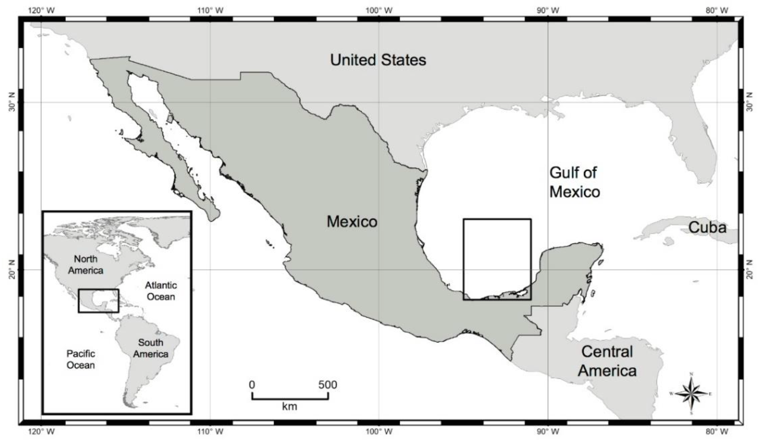
Notwithstanding the relative neglect of research projects on the use of satellite sensors for the discrimination of the oil-slick category, Carvalho [19] showed it is feasible to use SAR-derived measurements for seep-spill discrimination—see also [20,21,22]. These authors have used a series of Multivariate Data Analysis Techniques to devise a novel idea to discriminate the oil-slick category while studying seeps and spills observed on the surface of the ocean in the Gulf of Mexico off the Mexican coast in the Campeche Bay region (Figure 1). They have proposed a simple Oil-Slick Discrimination Algorithm based on SAR backscatter signature, i.e., sigma-naught (σo), beta-naught (βo), and gamma-naught (γo) [23,24,25], along with the geometry, shape, and dimension of the oil slicks. Their best outcome is reached with optimal Overall Accuracies of approximately 70%, based on the oil slicks’ areas and perimeters.
We report on analyses to refine the ability to discriminate the petrogenic oil-slick category (seeps versus spills) proposed in our previous investigations [19,20,21,22]. Exploiting the same dataset, but with expanded Data Processing Segments, we extend our earlier studies onto a firmer basis. Based on our methodical data mining exercise, we seek to improve the seep-spill discrimination accuracy, as well as to answer three scientific questions:
  • Among the several Data Transformation Approaches we tested, which one provides the most accurate oil-slick category discrimination?
  • Is there a specific Attribute Selection Process that excels at choosing variables to discriminate seeps from spills?
  • Which combination of Oil-Slick Information Descriptors promotes the best discrimination between seeps and spills?

2. Methods

We developed a comprehensive Exploratory Data Analysis (EDA) to reveal hidden information contained in the satellite-derived measurements and to refine the analysis to discriminate slicks by category, as proposed in our earlier studies [19,20,21,22]. The design of our EDA focuses on a data-driven scheme to investigate possible ways to improve the seep-spill discrimination with the simplest possible analysis and the lowest satellite-imaging cost. The research strategy employed herein is a development of our previous investigations [19,20,21,
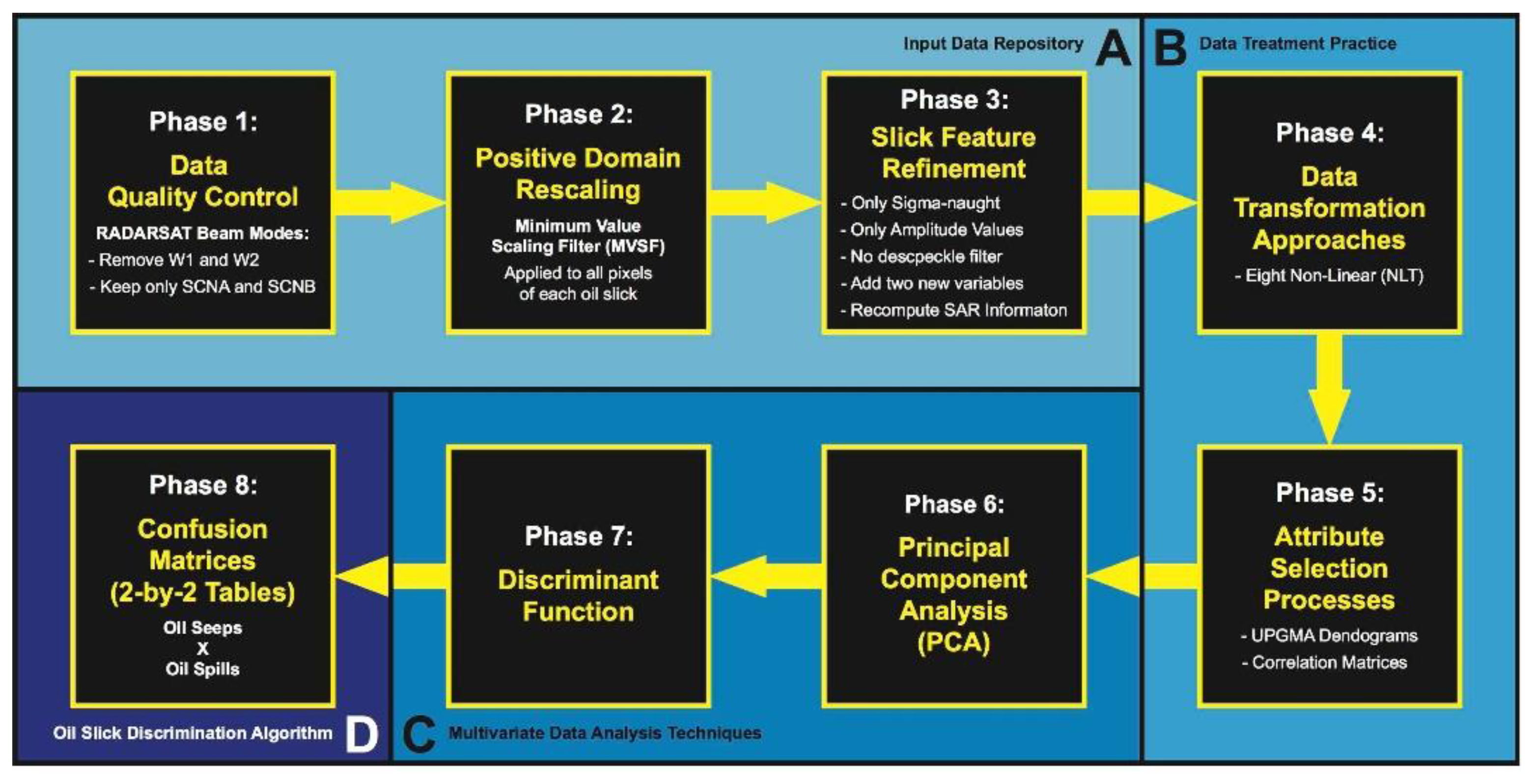
22], and consists of four distinct Data Processing Segments (i.e., A, B, C, and D in Figure 2)—devised in eight individual Phases—separately described in detail and introduced in a complete manner easily enabling replicability of our data mining exercise. A summary of our EDA design is depicted in Figure 2. While in-house Python codes are used to run the oil slick RADARSAT-2 related analyses (i.e., Phases 1–4), PAST (PAleontological STatistics: version 3.20, Oslo, Norway [26]) is used in the implementation of Phases 5–8.
A multi-year dataset of RADARSAT-2 scenes imaged between 2008 and 2012 gave rise to the oil slick data archive analyzed in our earlier investigations [19,20,21,22]. This data archive consists of polygons representative of oil slicks that had been identified and field validated as seeps and spills by domain experts. For more information about this dataset, see [19,20,21,22]. The workable dataset explored herein is defined after fine-tuning this data archive along the 1st Data Processing Segment (Figure 2A: Input Data Repository—Phases 1–3).

2.1. Phase 1: Data Quality Control

The initial oil slick data archive from our previous studies [19,20,21,22] is sorted by the satellite scene-imaging configuration (i.e., beam modes determining the acquisition swath width and ground resolution), thus establishing the amount of RADARSAT-2 imagery and the seeps and spills of our workable dataset.

2.2. Phase 2: Positive Domain Rescaling

The initially available oil slick data archive analyzed in our earlier investigations [19,20,21,22] had undergone a linear scaling action (Negative Values Scaling Filter: NVSF) that is comprised of a two-fold procedure applied to individual oil slicks: the subtraction of the minimum negative pixel value within each oil slick from every single pixel of such oil slick, followed by the addition of 1 to every single pixel—the minimum pixel value becomes 1. This brings all pixel values to the positive domain, which is a requirement of data normalization procedures that cannot be applied to negative values, e.g., log10. The NSVF is applied at the pixel level, i.e., taking into account all pixels of each oil slick to provide a single measure representative of all pixels of such oil slick (see below: Section 2.3.2). Nevertheless, previously, the NVSF was only applied to certain oil slicks: those having at least one negative pixel value—for instance, oil slicks that had spurious negative SAR backscatter signature caused by intrinsic multiplicative random granular speckle noise destructive imprecision in the range-dependent gain calculation [27,28].
Although we also conduct this filtering strategy, we apply it in the present research to all oil slicks. In essence, hereafter, for our purpose, the NVSF is referred to as Minimum Values Scaling Filter (MVSF), such that: PIXpos = (PIX-PIXmin) + 1, in which PIXpos corresponds to the new positive pixel value, PIX is the original pixel value, PIXmin is the minimum pixel value of all pixels of each oil slick. Therefore, this is a dissimilarity between our previous investigations and the current EDA: NVSF versus MVSF. The reason for applying the MVSF to all oil slicks is three-fold: (1) To avoid possible biases caused by gradient differences among oil slicks with and without NVSF; (2) To circumvent the application of despeckle filtering (e.g., Frost Filter: FFrost [29]; see also Phase 3) that eventually would eliminate negative values, but would alter (e.g., smoothing) the SAR backscatter signature values—the lack of such filter is justifiable to preserve the data-driven design of our EDA; and (3) To exploit data transformations that do not accept negative values (see below: Phase 4).

2.3. Phase 3: Slick Feature Refinement

2.3.1. SAR Backscatter Signature

Previously, we explored twelve SAR backscatter signatures: SAR backscatter coefficients corresponding to the radar cross-section (RCS: σ) normalized by the unit area calculated in three different surface planes (i.e., σo, βo, and γo [30,31,32,33,34]) computed in four radiometric-calibrated image products—i.e., the amplitude (1st) of the received radar beam and its dimensionless physical quantity form that represents power expressed in dB (2nd), both with (3rd) and without (4th) despeckle filtering (FFrost: 3-by-3 window). However, herein we perform a simplification for a more controlled EDA solely using σo given in amplitude without despeckle filtering. As such, from this point onwards, unless otherwise stated, any reference to SAR backscatter signature synonymously refers to this simplification.

2.3.2. Oil-Slick Information Descriptors

As before [19,20,21,22], we start our research analyzing the same ten attributes describing the oil slicks’ geometry, shape, and dimension (these are collectively referred to as Size Information Descriptors) derived from two basic morphological features characterizing the oil slicks—i.e., area (Area) and perimeter (Per):
  • AtoP: Area to Per ratio;
  • PtoA: Per to Area ratio [35];
  • PtoAnor: Normalized Per to Area ratio = Per/[(2.(Pi.Area))1/2] [36];
  • Complex Index = [Per2]/Area [37];
  • Compact Index = [4.Pi.Area]/[Per2] [18];
  • Shape Index = [Per/4]/[Area1/2] [38];
  • Fractal Index = [2.Ln(Per/4)]/[Ln(Area)] [39];
  • LEN: Number of pixels of each oil slick polygon.
Analogously, we also exploit the same 36 basic descriptive statistics metrics experimentally explored to characterize the oil slicks’ SAR backscatter signature as in our previous investigations [19,20,21,22]. These metrics are calculated based on all pixels inside individual oil slick polygons:
  • Four central tendency measures: Average (AVG), Median (MED), Mode (MOD), and Mid-mean (MDM: mean of the values between the 2nd and 3rd interquartiles, i.e., it trims off 25% of both ends);
  • Six measures of dispersion: Range (RNG), Coefficient of Dispersion (COD: the subtraction of the 1st interquartile from the 3rd interquartile and the division by their sum), Standard Deviation (STD), Variance (VAR), Average Absolute Deviation (AAD: mean of the absolute difference of each value to the mean), and Median Absolute Deviation (MAD: median of the absolute difference of each value minus the median);
  • 24 pair-values of Coefficients of Variation (COV: ratio between STD and AVG [18], such that each of the six dispersion measures are individually divided by the four central tendencies);
  • The Minimum (MIN) and Maximum (MAX) pixel values of each oil slick.
Herein we introduce two new variables that describe the distribution patterns of the pixels within each oil slick: Skewness (SKW) and Kurtosis (KUR). As such, this collection of 38 basic descriptive statistics metrics characterizing the oil slick’s SAR backscatter signature is henceforth referred to as SAR Information Descriptors. Together, these two types of Oil-Slick Information Descriptors (i.e., Size and SAR) determine the initial number of variables (48) accounted in our workable dataset.

2.4. Phase 4: Data Transformation Approaches

In contrast with our previous investigations [19,20,21,22], which implemented only a single non-linear normalization (log10) and one linear standardization (Ranging [40]), we exploit several Non-Linear Transformations (NLTs [41,42,43,44]):
  • NLT.0: No Transformation (x);
  • NLT.1: Reciprocal (1/x);
  • NLT.2: Logarithm Base 10 (log10(x));
  • NLT.3: Napierian Logarithm (Ln(x));
  • NLT.4: Square Root (x1/2);
  • NLT.5: Square Power (x2);
  • NLT.6: Cube Root (x1/3);
  • NLT.7: Third Power (x3).
In which x corresponds to the actual value of each oil slick variable (i.e., Oil-Slick Information Descriptors—see Phase 3). Half of these (i.e., NLT.1, NLT.2, NLT.3, and NLT.4) do not accept negative values (x). To simplify our analyses, we do not perform linear standardizations.

2.5. Phase 5: Attribute Selection Processes

The processes of selecting relevant attributes deals with the complex matter of reducing dimensionality in the variable-hyperspace domain (see also Phase 6); this generally helps to elucidate the problem solution of numerical ecology assessments and to improve the performance of classification algorithms [42,45]. As such, another difference from our earlier studies is the number of explored attributes: before, we investigated 44 data sub-divisions with 502, 433, 423, 151, 141, 35, 10, and 2 variables [19,20,21,22]. Indeed, we considerably reduce these numbers with the SAR backscatter signature simplification (see Phase 3: Section 2.3.1). Additionally, we start with 48 Oil-Slick Information Descriptors (see Phase 3: Section 2.3.2) but use even fewer variables upon the completion of the Attribute Selection Processes (see below: Section 2.5.1).

2.5.1. Unweighted Pair Group Method with Arithmetic Mean (UPGMA)

Two attribute selection strategies (i.e., R-mode) have been performed in our previous investigations [19,20,21,22]: UPGMA [42,43,46] and CFS (Correlation-Based Feature Selection [47,
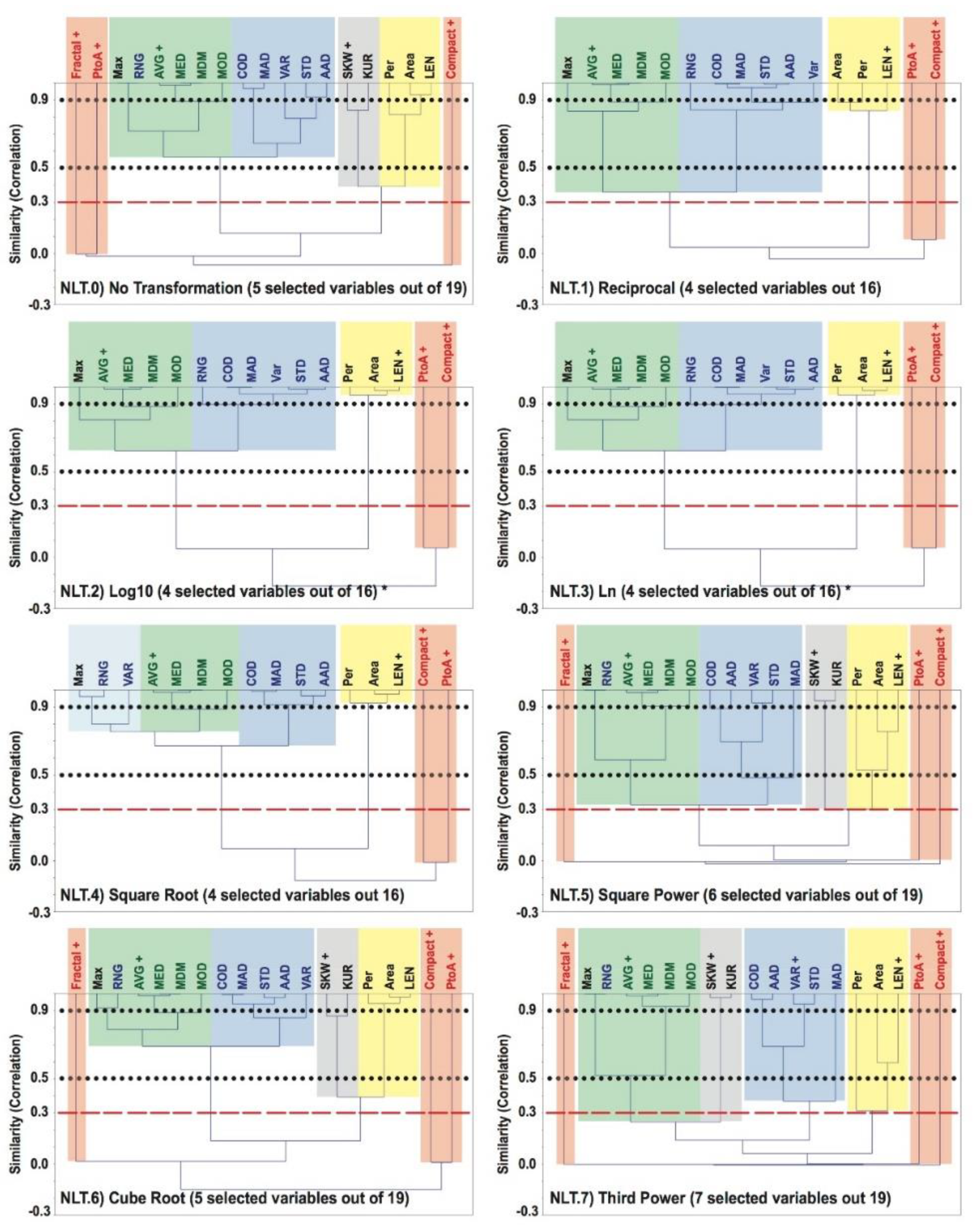
48]). Based on our earlier results, we only implement the former as it allows a user-defined strategy to select relevant variables: the choice of the similarity index (Pearson’s r correlation coefficient) used in the UPGMA dendrogram as cut-off to form groups of similar variables, i.e., phenon line [49,50]. See also [19,20,21,22] for further information about analyses and interpretations of rooted tree UPGMA dendrograms.
Moreover, an imperative distinction from our earlier investigations is that herein we are experimenting the use of a strict cut-off level, i.e., a fixed similarity value of 0.3, in relation to the previous fixed value of 0.5 and varying one ranging around 0.9 [19,20,21,22]. The selection of the 0.3 similarity cut-off is enlightened by the Bonferroni Adjustment as the level of minimum significance (p value) for large datasets (n > 100); below this there is no statistically significant correlation and variables are considered different from one another [51].

2.5.2. Histograms and Correlation Matrices

Histograms and correlation matrices assist in the verification of residual inter-variable correlation and to help with the decision of which variables to select on the groups formed on the UPGMA analyses.

2.6. Phase 6: Principal Component Analysis (PCA)

PCAs reduce the large correlated variables set into a smaller set of uncorrelated hypothetical variables—Principal Components (PCs)—containing most of the relevant information of the initial larger set [42,43]. The rotation of the original axes to the new orthogonal coordinate system is implemented in the same manner as our earlier work: square symmetric correlation matrix and 1000 bootstraps [52]. However, the approach to select relevant axes (i.e., PCs) is a departure from our earlier investigations. While, herein we use only the Kaiser Cut, i.e., Kaiser-Guttman criterion (eigenvalues > 1 [53]), previously we explored several PC-selection practices, e.g., Jolliffe, Scree Plot (Knee/Elbow), and a combined strategy using the Scree Plot (broken stick) with Kaiser [54,55,56,57].

2.7. Phase 7: Discriminant Function

Discriminant Analysis differs from Clustering Analysis as it is not meant to determine to which group each object belongs [43]. Instead, Discriminant Functions use a priori measured information (Oil-Slick Information Descriptors) and knowledge of the object’s (oil slick) group membership (seep or spill), to obtain the maximum discriminating power that minimizes the probability of erroneous discrimination: [DF(X) = (W1X1 + W2X2 + … + WnXn)−Coff]; in which DF(X) corresponds to the dependent variable (i.e., Discriminant Function); Xn to the independent variables (i.e., Oil-Slick Information Descriptor value); Wn to the independent variables’ weight; and Coff to the constant offset [58,59,60,61].
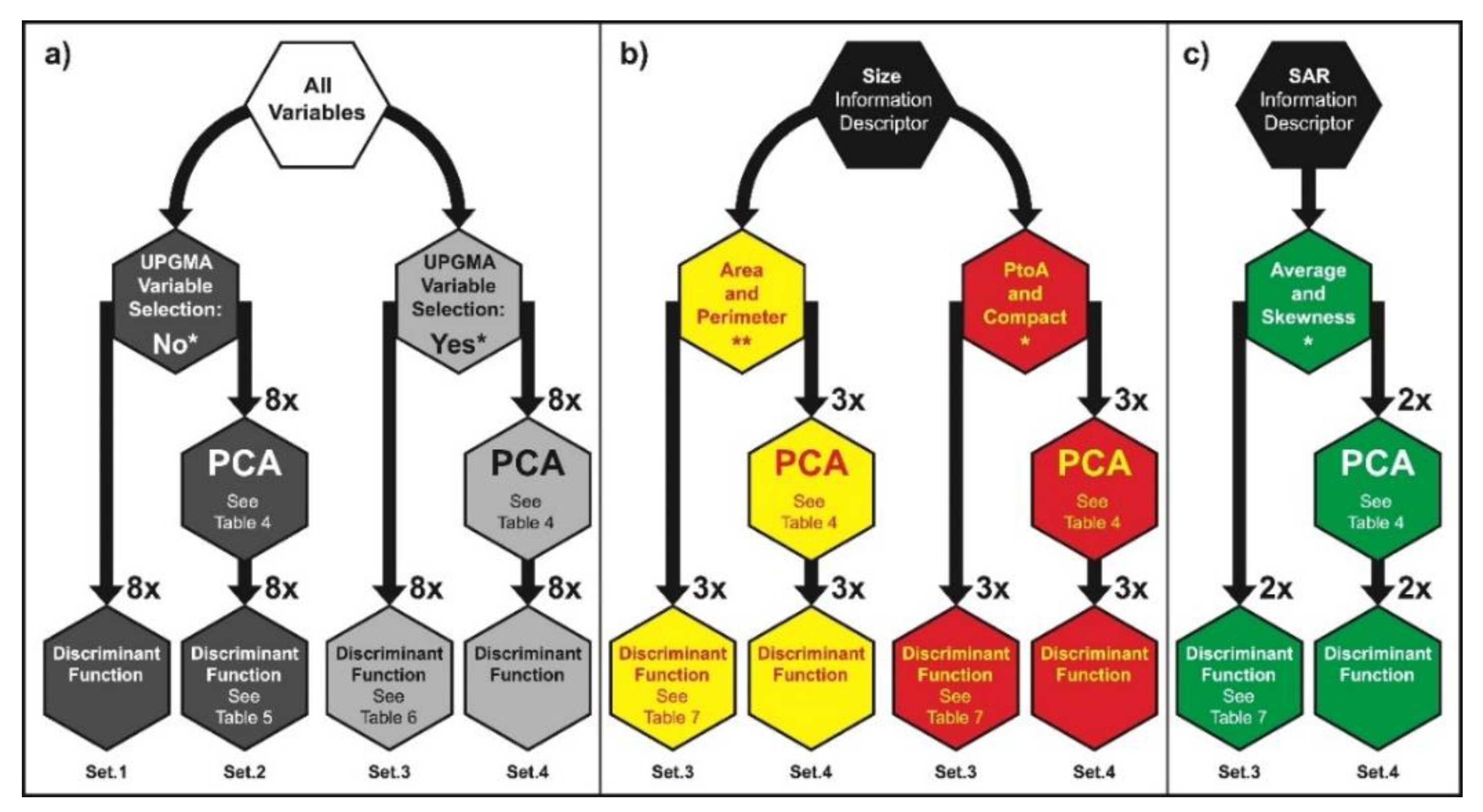
The use of uncorrelated attributes (selected PCs from Phase 6), or at least with the lowest possible degree of dependence (UPGMA selected variables from Phase 5), is a pressing need for Discriminant Functions [62], and as such, this concerns a crucial development of the current EDA from our previous investigations [19,20,21,22]: herein, we are not only using the PCA scores (PCs) as input to the Discriminant Functions, we are also testing the use of UPGMA dendrogram selected variables (see Phase 5: Section 2.5.1) without passing through the PCA.

2.8. Phase 8: Confusion Matrices (2-by-2 Tables)

The Oil-Slick Discrimination Algorithm accuracy is reported based on the Discriminant Function results by means of the complete understanding of adapted 2-by-2 Tables (Confusion Matrices: CMs). See also [19,20,21,22,63,64,65] for information on how to analyze and to better interpret 2-by-2 Tables. The conjunct interpretation of five metrics [66] is essential to fully evaluate the algorithm’s effectiveness. Table 1 gives a picture of these metrics that are color-coded for clarity:
  • CM.1: Overall Accuracy (shown in Green);
  • CM.2: Producer’s Accuracy (i.e., Sensitivity and Specificity—shown in Yellow);
  • CM.2: Commission Error (i.e., False Negative and False Positive);
  • CM.3: User’s Accuracy (i.e., Positive and Negative Predictive Values—shown in Purple);
  • CM.3: Omission Error (i.e., Inverse of the Positive and Negative Predictive Values).

3. Results and Discussion

3.1. Phase 1: Data Quality Control

The initially available oil slick data archive is composed of 4,916 oil slick polygons—2021 oil seeps (41%) and 2895 oil spills (59%)—imaged with 277 RADARSAT-2 scenes (Table 2 I), all of which are 16-bit and VV polarized [19,20,21,22]. These include two different RADARSAT beam modes—Wide [W1 and W2: 354 oil slicks (7%)] and ScanSAR Narrow [SCNA and SCNB: 4562 oil slicks (93%)]—that own two fundamental imaging differences: (1) W1 and W2 are Single Beam Modes (i.e., a strip-map SAR mode with certain imaging aspects constant along the entire scene), whereas SCNA and SCNB are ScanSAR Modes (i.e., combine two or more of the Single Beam Modes) [67]; the latter provides larger area coverage: swath width of 300 km—almost twice that of W1 and W2: 170 km and 150 km, respectively; and (2) Wide has a finer ground resolution of 25 m, which is ¼ of the ScanSAR Narrow one: 50 m.
Regarding their specification differences, eventual inaccuracies may be introduced to beam mode cross-comparisons. Notwithstanding that W1 and W2 provide better delineation of smaller oil slicks with their finer ground resolution, only SCNA and SCNB are kept in our analysis as these represent more than 90% of the available scenes. Furthermore, the ScanSAR Narrow swath width is more appropriate for monitoring applications requiring large-scale coverage such as the one that gave rise to the initially available oil slick data archive [19,20,21,22]. In fact, the lower scene cost of using ScanSAR Narrow to monitor larger ocean regions is rather preferable than the smaller area coverage of the Wide images.
Consequently, our workable dataset is composed of the collection of oil slick polygons imaged with the two ScanSAR Narrow beam modes: 4562 oil slicks—1994 oil seeps (44%) and 2568 oil spills (56%)—Table 2 II. Despite the fact that our EDA has 7% (354) fewer oil slicks than our previous study [19,20,21,22], representing about 1% (27) fewer seeps and approximately 11% (327) fewer spills (Table 2 III), such data reduction results in a more balanced dataset as compared to the one explored in our previous investigations, i.e., a smaller difference between the number of analyzed spills and seeps: 13% instead of 18% (Table 2: I–II). Indeed, this provides a firmer basis in the oil-slick category discrimination. Moreover, the oil slick polygons imaged with SCNA and SCNB come from 244 RADARSAT-2 scenes imaged between 2008 and 2012—12% (33) fewer images than our earlier investigations (Table 2).

3.2. Phase 2: Positive Domain Rescaling

As the MVSF is applied at the pixel level to all oil slicks in our workable dataset (Table 2 II: 4562), it affects the values of the 38 SAR Information Descriptors but not of the 10 Size Information Descriptors (see Phase 3: Section 2.3.2). The latter is independent of the MVSF application as they are derived from and include the two basic morphological oil slick features: Area and Perimeter.

3.3. Phase 3: Slick Feature Refinement

The consequence of MVSF (see Phase 2) is two-fold: (1) the SAR Information Descriptors are not the same as in our previous investigations and need to be recomputed for all analyzed oil slicks; (2) MIN loses its meaning as its value for all oil slicks becomes 1; accordingly, it is not pursued in our analysis.

3.4. Phase 4: Data Transformation Approaches

Although the NLTs can be independently applied to each attribute, for consistency, during our EDA, all-numeric variables uniformly undergo the same column-wise transformation. Because three Oil-Slick Information Descriptors—i.e., Fractal, SKW, and KUR—have values that range from negative to positive, they are not used on half of the NLTs that require only positive values: NLT.1; NLT.2; NLT.3; and NLT.4.

3.5. Phase 5: Attribute Selection Processes

Histograms show that the distribution of some Size Information Descriptors is the same as others, sometimes being inverted independent of NLT, meaning that there is no new information revealed. As a result, only one of these variables is selected, for instance: (1) AtoP and PtoA have equal but inverted distributions; (2) PtoAnor, Complex, Compact, and Shape, also have equal distribution but Compact is inverted from the three other. Of these variables, we only keep PtoA and Compact, as Area and Perimeter appear in opposition in their formula: PtoA has area in the denominator, as opposed to Compact, which has area in the numerator; the contrary holds true for the perimeter (see Phase 3: Section 2.3.2).

3.5.1. Unweighted Pair Group Method with Arithmetic Mean (UPGMA)

The combined analysis of dendrograms and correlation matrices show that the 24 COV pair-values have a strong intra-correlation, as well as that they are highly correlated with most of the other variables; hence, they are not further explored. Therefore, out of the 48 initial Oil-Slick Information Descriptors (see Phase 3: Section 2.3.2), only 19 remain for further analyses—Size (6): Area, Per, PtoA, Compact, Fractal, and LEN; and SAR (13): AVG, MED, MOD, MDM, RNG, COD, STD, VAR, AAD, MAD, MAX, SKW, and KUR. However, only half of the NLTs (NLT.0, NLT.5, NLT.6, and NLT.7) utilize these 19 variables; the other half (NLT.1, NLT.2, NLT.3, and NLT.4) explores three fewer Oil-Slick Information Descriptors, i.e., only 16 variables (see Phase 4: Section 3.4).
Figure 3 depicts eight UPGMA dendrograms (one for each of the analyzed NLT), in which it is possible to observe a number of differences, as well as resemblances, between them; mostly regarding inter-variable correlations. An evident characteristic of the two Logarithm functions (NLT.2: Log10; and NLT.3: Ln) is that their dendrograms are equal; the same holds true for their correlation matrices that are also identical.
Prior to the uncorrelated variables selection, we have to identify the groups of correlated variables. The process of defining and/or interpreting groups in UPGMA dendrograms is quite subjective [43], but, at first glance, the global picture of Figure 3 clearly reveals how equivalent are the groups between the several NLTs; these are color-coded for clarity. In the visual analysis of Figure 3, one can note that variables tend to group based on their main characteristics, following the Oil-Slick Information Descriptor features, such that:
  • Green: Measures of central tendency (AVG, MED, MOD, and MDM);
  • Blue: Dispersion measures (RNG, COD, STD, VAR, AAD, and MAD);
  • Grey: Metrics of pixel distribution (SKW and KUR);
  • Yellow: Basic morphological features (Area and Per) and LEN;
  • Red: Ratios derived from the morphological features (PtoA, Compact, and Fractal).
An advanced analysis of the UPGMA dendrograms shown in Figure 3 discloses that:
  • The three morphological ratios (Red group) are not correlated with any other variable (similarity close to or equal to zero)—PtoA and Compact form an uncorrelated group, and Fractal usually stands alone; the exception is in NLT.0 where Compact is the one by itself;
  • The two groups of SAR Information Descriptor, i.e., Green (central tendency) and Blue (dispersion), generally form a larger group—Geen + Blue—the exception is in NLT.7;
  • The Grey group (pixel distribution metrics) is usually correlated with the Yellow group (basic morphological features)—Grey + Yellow group—the exception is in NLT.7 where it groups with the Green group (measures of central tendency);
  • RNG is an exception in three NLTs (NLT.0, NLT.6, and NLT.7) as it correlates with the central tendency variables (Green group);
  • MAX groups among the central tendency variables (Green group) except in NLT.4.
The phenon line, represented by the horizontal red dashed line in Figure 3 (i.e., 0.3 Pearson’s r correlation coefficient) defines the actual groups from which we select one variable of each—groups are formed when this cut-off line crosses a vertical line (i.e., branch or edge) [49,50]. In fact, the groups formed in this manner match the preliminary visual analysis of the dendrograms:
  • Three groups are observed (Green + Blue, Yellow, and one Red) when 16 variables are analyzed, i.e., NLT.1, NLT.2, and NLT.3—NLT.4 is an exception;
  • Four other groups are also formed (Green + Blue, Grey + Yellow, and two Red ones) when 19 variables are accounted for, i.e., NLT.0, NLT.5, NLT.6—NLT.7 is an exception;
  • Three other groups are formed in NLT.4 (16 variables) in which VAR, RNG, and MAX cluster together forming an extra assemblage (Light Blue)—Light Blue + Green + Blue, Yellow, and one Red;
  • Six groups are formed in NLT.7 (19 variables): Green, Grey, Blue, Yellow, and two Red ones.
One should pay close attention to the two Red groups, as from them, three variables are selected—e.g., NLT.0 (Fractal, PtoA, and Compact)—because such variables have no correlation.
The number of selected variables ranges between 4 and 7 variables, depending on the NLT (Table 3), such that:
  • AVG is selected from the Green + Blue group to maintain the simplest possible analysis;
  • VAR is selected when the Blue group is alone (only in NLT.7) to keep it simple as possible;
  • SKW is preferable from the Grey group as it measures asymmetry;
  • LEN is selected from the Yellow group as Area and Perimeter are both present in the ratios;
  • The three morphological ratios (Red group: PtoA, Compact, and Fractal) are always selected when present.

3.6. Phase 6: Principal Component Analysis (PCA)

The scatterplots show a large overlap between seeps and spills, but their centroids are somehow distinctively independent of NLT. When all variables (16 or 19) are directly input to the PCA, the cumulative variance of the selected PCs (3 to 7) ranges between 80 to 90% for all NLTs. However, when the input is the UPGMA selected variables (4 to 7), the PC-selection (2 to 4 PCs) shows a much lower cumulative variance: from 52% to 70%; the exceptions are the Logarithm functions (NLT.2: Log10; and NLT.3: Ln) with 99.5% (2 PCs). Table 4 reports the number of selected PCs and their cumulative variance per NLT.

3.7. Phase 7: Discriminant Function

As we are comparing the results of using the score values of the selected PCs versus the use of actual values of the Oil-Slick Information Descriptors, both directly input to the Discriminant Analysis, four different Discriminant Function sets are analyzed per NLT:
  • Set.1: No UPGMA variable selection, i.e., all variables (16 or 19), without PCA;
  • Set.2: No UPGMA variable selection, i.e., all variables (16 or 19), with PCA (3 to 7 PCs);
  • Set.3: UPGMA selected variables (4 to 7) without PCA;
  • Set.4: UPGMA selected variables (4 to 7) with PCA (2 to 4 PCs).
Figure 4 portrays the scheme defining these four input dataset versions for each NLT (8x). Another improvement from our earlier studies is that besides exploring the seep-spill discrimination capabilities of using the PC-scores and values of the variables, as well as the sole use of Area with Perimeter as before [19,20,21,22], we also test a separate analysis with a pair of Size Information Descriptors (PtoA with Compact) and with a pair of SAR Information Descriptors (AVG with SKW)—see Figure 4. These are chosen based on the interpretation of the UPGMA dendrograms (Phase 5: Section 3.5.1—see also Figure 3). Although the histograms of the Discriminant Functions’ axes show that seep and spill properties overlap, independent of NLT, their centroids are separate.

3.8. Phase 8: Confusion Matrices (2-by-2 Tables)

Each NLT is evaluated with the four input dataset versions (Figure 4), and usually, Set.1 presents the highest discrimination power. However, these variables (16 or 19) are strongly correlated (Figure 3) and do not fulfill a Discriminant Functions requirement to use independent, or the least as correlated as possible, attributes [62]. The second best discrimination accuracy occurs with Set.2, which is closely followed by Set.3. The lowest observed accuracies are from Set.4, as the selected PCs have a very low cumulative variance in the selected PCs; the exceptions are the Logarithm functions (NLT.2: Log10; and NLT.3: Ln—see Table 4).
The global analysis of all 32 Data Transformation Approaches combinations (i.e., eight NLTs versus four input dataset versions) demonstrates the Logarithm functions (NLT.2: Log10; and NLT.3: Ln) and Cube Root (NLT.6) as the most effective NLTs in supporting an accurate Oil-Slick Discrimination Algorithm. The Confusion Matrices evaluating the results of the Discriminant Functions for the several NLTs are shown on the color-coded Table 5 (Pink) and Table 6 (Red): Set.2 and Set.3, respectively. In the examination of these two tables that report the accuracy of the Oil-Slick Discrimination Algorithm, if taking the Log10 (NLT.2), for example, one can find that:
  • CM.1: Overall Accuracies ranging about 69%;
  • CM.2: Producer’s Accuracy, i.e., Sensitivities (65%) or Specificities (71%);
  • CM.2: Commission Error, i.e., False Negative (35%) and False Positive (29%);
  • CM.3: User’s Accuracy, i.e., Positive (64%) and Negative (73%) Predictive Values;
  • CM.3: Omission Error, i.e., Inverse of the Positive (36%) and Negative (27%) Predictive Values.
From Table 5 and Table 6, one verifies the successful, and similar, results of the Cube Root (NLT.6) in comparison to the Logarithm functions (NLT.2 and NLT.3). Additionally, the cross-comparison of the results from Set.2 (Table 5) and Set.3 (Table 6) indicates that these two attribute selection strategies—i.e., 1) no UPGMA variable selection with PCA; and 2) UPGMA selected variables without PCA—promote comparable seep-spill discrimination accuracies.
A careful analysis of Table 5 (Set.2) discloses that the preferred lowest rate of False Negatives (20.4%) and Inverse of the Positive Predictive Values (23.3%) are observed in NLT.1 (Reciprocal); however, their counterparts, i.e., False Positives (48.0%) and Inverse of the Negative Predictive Values (43.7%), have undesirable high values among all NLTs. As its Overall Accuracy is reasonable (64.07%), this is an example that one needs to look into the conjunct interpretation of the five main metrics shown in Table 1 [19,20,21,22,63,64,65]. Similarly, the cautious analysis of Table 6 (Set.3) reveals that an ideal low rate of False Negatives (11.7%) and Inverse of the Positive Predictive Values (21.8%) are observed in NLT.5 (Square Power), but on the other hand, their counterparts, i.e., False Positives (67.5%) and Inverse of the Negative Predictive Values (49.6%), have unwanted high values. In this case, its Overall Accuracy is quite low (56.90%) though.
When considering the separate analysis of the Oil-Slick Information Descriptors (i.e., Size and SAR), Set.3 and Set.4 (see Figure 4: without PCA and with PCA, respectively) present the same result—these are shown in Table 7. The foremost outcome revealed in Table 7 is that the sole use of SAR Information Descriptors (AVG with SKW) is not as effective as using only Size Information Descriptors (Area with Perimeter and PtoA with Compact). Table 7 also discloses that these two pairs of Size Information Descriptors have the same results in the Logarithm function (NLT.2), and in fact, these results present superior discrimination power than in the other two analyzed NLTs, i.e., NLT.0 (No Transformation) and NLT.6 (Cube Root). Slightly better Overall Accuracies are achieved when using Area with Perimeter than PtoA with Compact; however, one should note that the False Negatives of the former pair are much higher than those of using the second pair: 67.7% against 21.0% (NLT.0), and 43.4% against 28.9% (NLT.6).
We can also evaluate the results of using several variables (Table 5 and Table 6) against the use of individual pairs of attributes, i.e. the separate analysis of Size and SAR Information Descriptors (Table 7). If one compares the outcomes of NLT.2 (Log10) in Table 5, Table 6 and Table 7, it is possible to notice that the sole use of the two Size Information Descriptor pairs (Table 7) has equivalent results as the ones from the other two attribute selection strategies, i.e., no UPGMA variable selection with PCA (Set.2: Table 5) versus UPGMA selected variables without PCA (Set.3: Table 6).

4. Conclusions

Our research addresses a gap in our scientific knowledge regarding the discrimination of the oil-slick category, i.e., sea surface expression of oil seeps versus oil spills observed in Campeche Bay (Figure 1). We report on analyses to refine the ability of using SAR-derived measurements for this task, thus addressing expanded Data Processing Segments (A, B, C, and D in Figure 2) as compared to our previous investigations [19,20,21,22]. A firmer basis to discriminate slicks by category has been established with the specific data-driven design of our Exploratory Data Analysis (EDA). An innovative strategy to select uncorrelated attributes based on the Bonferroni Adjustment (i.e., Pearson’s r correlation coefficient of 0.3 [51]) has been successfully implemented using rooted tree dendrograms (Unweighted Pair Group Method with Arithmetic Mean: UPGMA—see Figure 3). We investigate several Non-Linear Transformations (NLTs—see Phase 4: Data Transformation Approaches) and various strategies to select uncorrelated attributes: we tested more than 32 combinations of Data Transformation Approaches, i.e., eight NLTs versus four input dataset versions (see Set.1, Set.2, Set.3, and Set.4 in Phase 7: Discriminant Function—Figure 4).
Based on our comprehensive approach to find a simple way to discriminate seeps from spills, we are able to answer the three scientific questions:
  • The two Logarithm functions (NLT.2: Log10; and NLT.3: Ln) and Cube Root (NLT.6) have the most accurate seep-spill discrimination among the eight Data Transformation Approaches tested.
  • Of the different strategies tested for selecting relevant attributes (i.e., four input dataset versions—see Phase 7: Section 3.7), two (Set.2 and Set.3) have comparable discrimination power with Overall Accuracies of almost 70%; however, the sole use of UPGMA dendrograms (i.e., Set.3) excels at selecting uncorrelated variables as it provides a simpler form avoiding the implementation of additional Multivariate Data Analysis Techniques (i.e., PCA). This is clearly observed in an inspection of Table 6 (Set.3) and in a comparison with Table 5 [Set.2: the use of all variables (see Phase 5: Section 3.5.1Figure 3 and Table 3) without the dendrogram selection (i.e., no UPGMA) but with the application of the PCA (see Phase 6: Section 3.6Table 4)].
  • The use of a collection of variables from two attribute selection strategies, i.e., Set.2 [no UPGMA with PCA (19 or 16 attributes but with 3 to 7 PCs—Table 5)] and Set.3 [UPGMA and no PCA (4 to 7 variables—Table 6)] is equally capable of discriminating seeps from spills. However, these are comparable to the sole use of the two Size Information Descriptor pairs (Area with Perimeter and PtoA with Compact) that outperform the SAR Information Descriptor pair (AVG with SKW)—see Table 7.
Our EDA also demonstrates that using simple and low-cost RADARSAT-2 beam modes (SCNA and SCNB), one can achieve useful seep-spill discrimination accuracies, thus supporting new products for the RADARSAT Constellation Mission (RCM): RADARSAT-2 Mode Selection for Maritime Surveillance (R2MS2).

Author Contributions

The paper was conceived and written by G.A.C. under the supervision of P.J.M., E.T.P., F.P.M., and L.L. All authors participated of the research conceptualization, experiment design, data analysis/interpretation, as well as of the investigation quality improvement, read, edit, and approval of the final manuscript.

Funding

Financial support has been provided by the Programa Nacional de Pós Doutorado (PNPD) of Coordenação de Aperfeiçoamento de Pessoal de Nível Superior (CAPES), Brazil.

Acknowledgments

We thank Pemex and MDA Geospatial Services for the RADARSAT-2 dataset, as well as we are pleased with the support received from COPPE/UFRJ: LabSAR colleagues, LAMCE staff, and PEC employees.

Conflicts of Interest

The authors declare no conflict of interest.

References

  1. NRCC (National Research Council Committee). Oil in the Sea: Inputs, Fates, and Effects; The National Academies Press: Washington, DC, USA, 1985. [Google Scholar]
  2. NRCC (National Research Council Committee). Oil in the Sea III: Inputs, Fates, and Effects; The National Academies Press: Washington, DC, USA, 2003; ISBN 9780309084383. [Google Scholar]
  3. Fingas, M.F.; Brown, C.E. Review of oil spill remote sensing. Spill Sci. Technol. Bull. 1997, 4, 199–208. [Google Scholar] [CrossRef]
  4. Fingas, M.F.; Brown, C.E. Oil-spill remote sensing—An update. Sea Technol. 2000, 41, 21–26. [Google Scholar]
  5. Fingas, M.; Brown, C.E. A Review of Oil Spill Remote Sensing. Sensors 2018, 18, 91. [Google Scholar] [CrossRef] [PubMed]
  6. Asanuma, I.; Muneyama, K.; Sasaki, Y.; Iisaka, J.; Yasuda, Y.; Emori, Y. Satellite thermal observation of oil slicks on the Persian Gulf. Remote Sens. Environ. 1986, 19, 171–186. [Google Scholar] [CrossRef]
  7. Bulgarelli, B.; Djavidnia, S. On MODIS retrieval of oil spill spectral properties in the marine environment. IEEE Geosci. Remote Sens. Lett. 2012, 9, 398–402. [Google Scholar] [CrossRef]
  8. Brown, C.E.; Fingas, M. New space-borne sensors for oil spill response. In Proceedings of the International Oil Spill Conference, Tampa, FL, USA, 26–29 March 2001; pp. 911–916. [Google Scholar]
  9. Brown, C.E.; Fingas, M. The latest developments in remote sensing technology for oil spill detection. In Proceedings of the Interspill Conference and Exhibition, Marseille, France, 12–14 May 2009; p. 13. [Google Scholar]
  10. Alpers, W.; Holt, B.; Zeng, K. Oil spill detection by imaging radars: Challenges and pitfalls. Remote Sens. Environ. 2017, 201, 133–147. [Google Scholar] [CrossRef]
  11. Staples, G.C.; Hodgins, D.O. RADARSAT-1 emergency response for oil spill monitoring. In Proceedings of the 5th International Conference on Remote Sensing for Marine and Coastal Environments, San Diego, CA, USA, 5–7 October 1998; pp. 163–170. [Google Scholar]
  12. Staples, G.; Rodrigues, D.R. Maritime environmental surveillance with RADARSAT-2. In Proceedings of the XVI Brazilian Remote Sensing Symposium (SBSR), Foz do Iguaçu, Brazil, 13–18 April 2013; pp. 8445–8452. [Google Scholar]
  13. Genovez, P.C. Segmentação e Classificação de Imagens SAR Aplicadas à Detecção de Alvos Escuros em Áreas Oceânicas de Exploração e Produção de Petróleo. Ph.D. Dissertation, COPPE, Universidade Federal do Rio de Janeiro (UFRJ), Rio de Janeiro, Brazil, 2010; p. 235. [Google Scholar]
  14. Espedal, H.A. Detection of Oil Spill and Natural Film in the Marine Environment by Spaceborne Synthetic Aperture Radar. Ph.D. Dissertation, Department of Physics, University of Bergen and Nansen Environmental and Remote Sensing Center (NERSC), Bergen, Norway, 1998; p. 200. [Google Scholar]
  15. Johannessen, O.M.; Espedal, H.A.; Jenkins, A.J.; Knulst, J. SAR surveillance of ocean surface slicks. In Proceedings of the 2nd ERS Application Workshop, London, UK, 6–8 December 1995; pp. 187–192. [Google Scholar]
  16. Jackson, C.R.; Apel, J.R. Synthetic Aperture Radar Marine User’s Manual; NOAA/NESDIS, Office of Research and Applications: Washington, DC, USA, 2004; Freely Available online: http://www.sarusersmanual.com (accessed on 2 December 2018).
  17. Wismann, V.; Gade, M.; Alpers, W.; Huehnerfuss, H. Radar signatures of marine mineral oil spills measured by an airborne multi-frequency multi-polarization microwave scatterometer. Int. J. Remote Sens. 1998, 19, 3607–3623. [Google Scholar] [CrossRef]
  18. Bentz, C.M. Reconhecimento Automático de Eventos Ambientais Costeiros e Oceânicos em Imagens de Radares Orbitais. Ph.D. Dissertation, COPPE, Universidade Federal do Rio de Janeiro (UFRJ), Rio de Janeiro, Brazil, 2006; p. 115. [Google Scholar]
  19. Carvalho, G.A. Multivariate Data Analysis of Satellite-Derived Measurements to Distinguish Natural from Man-Made Oil Slicks on the Sea Surface of Campeche Bay (Mexico). Ph.D. Dissertation, COPPE, Universidade Federal do Rio de Janeiro (UFRJ), Rio de Janeiro, Brazil, 2015; p. 285. Freely Available online: http://www.coc.ufrj.br/index.php?option=com_content&view=article&id=4618:gustavo-de-araujo-carvalho (accessed on 2 December 2018).
  20. Carvalho, G.A.; Landau, L.; Miranda, F.P.; Minnett, P.; Moreira, F.; Beisl, C. The use of RADARSAT-derived information to investigate oil slick occurrence in Campeche Bay, Gulf of Mexico. In Proceedings of the XVII Brazilian Remote Sensing Symposium (SBSR), João Pessoa, Brazil, 25–29 April 2015; pp. 1184–1191. Freely Available online: http://www.dsr.inpe.br/sbsr2015/files/p0217.pdf (accessed on 2 December 2018).
  21. Carvalho, G.A.; Minnett, P.J.; Miranda, F.P.; Landau, L.; Moreira, F. The use of a RADARSAT-derived long-term dataset to investigate the sea surface expressions of human-related oil spills and naturally-occurring oil seeps in Campeche Bay, Gulf of Mexico. Can. J. Remote Sens. 2016, 42, 307–321. [Google Scholar] [CrossRef]
  22. Carvalho, G.A.; Minnett, P.J.; de Miranda, F.P.; Landau, L.; Paes, E.T. Exploratory Data Analysis of Synthetic Aperture Radar (SAR) Measurements to Distinguish the Sea Surface Expressions of Naturally-Occurring Oil Seeps from Human-Related Oil Spills in Campeche Bay (Gulf of Mexico). ISPRS Int. J. Geo-Inf. 2017, 6, 379. Freely Available online: https://www.mdpi.com/2220-9964/6/12/379 (accessed on 2 December 2018). [CrossRef]
  23. Freeman, A. Radiometric calibration of SAR image data. In Proceedings of the XVII Congress for Photogrammetry and Remote Sensing, Washington, DC, USA, 2–14 August 1992; pp. 212–222. [Google Scholar]
  24. Laur, H.; Bally, P.; Meadows, P.; Sanchez, J.; Schaettler, B.; Lopinto, E.; Esteban, D. ERS SAR Calibration: Derivation of the Backscattering Coefficient Sigma-Nought in ESA ERS SAR PRI Products; Document No.: ES-TN-RS-PM-HL09; ESA (European Space Agency): Paris, France, 1998; p. 51. [Google Scholar]
  25. Shepherd, N. Extraction of Beta Nought and Sigma Nought from RADARSAT CDPF Products; Technical Report, Revision 4, AS97-5001; Altrix Systems: Ottawa, ON, Canada, 2000; p. 16. [Google Scholar]
  26. Hammer, Ø.; Harper, D.A.T.; Ryan, P.D. PAST: PAleontological STatistics software package for education and data analysis. Palaeontol. Electron. 2001, 4, 1–9. [Google Scholar]
  27. Henderson, F.M.; Lewis, A.J. Principles and Applications of Imaging Radar, Manual of Remote Sensing, 3rd ed.; Wiley: Hoboken, NJ, USA, 1998; p. 866. [Google Scholar]
  28. Masoomi, A.; Hamzehyan, R.; Shirazi, N.C. Speckle reduction approach for SAR image in satellite communication. Int. J. Mach. Learn. Comput. 2012, 2, 62–70. [Google Scholar] [CrossRef]
  29. Frost, V.S.; Stiles, J.A.; Shanmugan, K.S.; Holtzman, J.C. A model for radar images and its application to adaptive digital filtering of multiplicative noise. IEEE Trans. Pattern Anal. Mach. Intell. 1982, 4, 157–166. [Google Scholar] [CrossRef] [PubMed]
  30. AIRBUS (Defense & Space). Radiometric Calibration of TerraSAR-X Data: Beta Naught and Sigma Naught Coefficient Calculation; Technical Report TSXXITD-TN-0049; AIRBUS: Friedrichshafen, Germany, 2014; p. 15. [Google Scholar]
  31. AIRBUS (Defense & Space). TerraSAR-X Value Added Product Specification; Technical Report TSXX-ITD-SPE-0009, Issue/Revision: 1/3; AIRBUS: Friedrichshafen, Germany, 2014; p. 26. [Google Scholar]
  32. El-Darymli, K.; Mcguire, P.; Gill, E.; Power, D.; Moloney, C. Understanding the significance of radiometric calibration for synthetic aperture radar imagery. In Proceedings of the 27th Canadian Conference on Electrical and Computer Engineering (CCECE), Toronto, ON, Canada, 4–7 May 2014; p. 6. [Google Scholar] [CrossRef]
  33. Thakur, P.K. SAR data processing to extract backscatter response from various features. In Proceedings of the Symposium Tutorials on Polarimetric SAR Data Processing and Applications, International Society for Photogrametry and Remote Sensing (ISPRS), Hyderabad, India, 9–12 December 2014. [Google Scholar]
  34. ASF (Alaska Satellite Facility). MapReady User Manual Remote Sensing Tool Kit; Engineering Group Fairbanks: Fairbanks, AK, USA, 2015; p. 120. [Google Scholar]
  35. Fiscella, B.; Giancaspro, A.; Nirchio, F.; Pavese, P.; Trivero, P. Oil spill monitoring in the Mediterranean Sea using ERS SAR data. In Proceedings of the Envisat Symposium (ESA), Göteborg, Sweden, 16–20 October 2010; p. 9. [Google Scholar]
  36. Singha, S.; Bellerby, T.J.; Trieschmann, O. Satellite Oil Spill Detection Using Artificial Neural Networks. IEEE J. Sel. Top. Appl. Earth Obs. Remote Sens. 2013, 6, 2355–2363. [Google Scholar] [CrossRef]
  37. Solberg, A.H.S.; Storvik, G.; Solberg, R.; Volden, E. Automatic detection of oil spills in ERS SAR images. IEEE Trans. Geosci. Remote Sens. 1999, 37, 1916–1924. [Google Scholar] [CrossRef]
  38. Pisano, A. Development of Oil Spill Detection Techniques for Satellite Optical Sensors and Their Application to Monitor Oil Spill Discharge in the Mediterranean Sea. Ph.D. Dissertation, Università di Bologna, Bologna, Italy, 2011; p. 146. [Google Scholar]
  39. Mcgarigal, K.; Marks, B.J. FRAGSTATS: Spatial Pattern Analysis Program for Quantifying Landscape Structure; General Technical Report Series, PNW-GTR-351; U.S. Department of Agriculture: Portland, OR, USA, 1994; p. 134. [Google Scholar]
  40. Milligan, G.W.; Cooper, M.C. A study of standardization of variables in cluster analysis. J. Classif. 1988, 5, 181–204. [Google Scholar] [CrossRef]
  41. Moita Neto, J.M.; Moita, G.C. Uma introdução à análise exploratória de dados multivariados. Química Nova 1998, 21, 467–469. [Google Scholar] [CrossRef] [Green Version]
  42. Legendre, P.; Legendre, L. Numerical Ecology, 3rd English ed.; Developments in Environmental Modelling; Elsevier Science B.V.: Amsterdam, The Netherlands, 2012; 990p, ISBN 978-0444538680. [Google Scholar]
  43. Valentin, J.L. Ecologia Numérica—Uma Introdução à Análise Multivariada de Dados Ecológicos, 2nd ed.; Editora Interciência: Rio de Janeiro, Brazil, 2012; p. 153. ISBN 978-85-7193-230-2. [Google Scholar]
  44. Lane, D.M.; Scott, D.; Hebl, M.; Guerra, R.; Osherson, D.; Ziemer, H. Introduction to Statistics; Online Edition; Rice University: Huston, TX, USA, 2015; p. 695. [Google Scholar]
  45. Guyon, I.; Elisseeff, A. An Introduction to Variable and Feature Selection. J. Mach. Learn. Res. 2003, 3, 1157–1182. [Google Scholar]
  46. Sneath, P.H.A.; Sokal, R.R. Numerical Taxonomy—The Principles and Practice of Numerical Classification; W.H. Freeman and Company: San Francisco, CA, USA, 1973; 573p, ISBN 0-7167-0697-0. [Google Scholar]
  47. Hall, M.A. Correlation-Based Feature Selection for Machine Learning. Ph.D. Dissertation, Department of Computer Science, The University of Waikato, Hamilton, New Zealand, 1999; p. 178. [Google Scholar]
  48. Bouckaert, R.R.; Frank, E.; Hall, M.; Kirby, R.; Reutemann, P.; Seewald, A.; Scuse, D. WEKA Manual for Version 3-6-0; The University of Waikato: Hamilton, New Zealand, 2008; p. 212. [Google Scholar]
  49. Sokal, R.R.; Rohlf, F.J. The Comparison of dendrograms by objective methods. Taxon 1962, 11, 33–40. [Google Scholar] [CrossRef]
  50. NCSS (Number Cruncher Statistical System). Hierarchical Clustering and Dendrograms; NCSS Statistical Software: Kaysville, UT, USA, 2015; Chapter 445; p. 15. [Google Scholar]
  51. Zar, H.J. Biostatistical Analysis, 5th ed.; Pearson New International Edition; Pearson: Upper Saddle River, NJ, USA, 2014; ISBN 1-292-02404-6. [Google Scholar]
  52. Peres-Neto, P.R.; Jackson, D.A.; Somers, K.M. Giving meaningful interpretation to ordination axes: Assessing loading significance in principal component analysis. Ecology 2003, 84, 2347–2363. [Google Scholar] [CrossRef]
  53. Kaiser, H.F. A note on Guttman’s lower bound for the number of common factors. Br. J. Stat. Psychol. 1961, 14, 1–2. [Google Scholar] [CrossRef]
  54. Cattell, R.B. The Scree Test for the number of factors. Multivar. Behav. Res. 1966, 1, 245–276. [Google Scholar] [CrossRef] [PubMed]
  55. Jolliffe, I.T. Principal Component Analysis, 2nd ed.; Springer: New York, NY, USA, 2002; p. 487. ISBN 0-387-95442-2. [Google Scholar]
  56. Peres-Neto, P.R.; Jackson, D.A.; Somers, K.M. How many principal components? Stopping rules for determining the number of non-trivial axes revisited. Comput. Stat. Data Anal. 2005, 49, 974–997. [Google Scholar] [CrossRef]
  57. Hammer, Ø. PAST: Multivariate Statistics. 2015. Freely Available online: http://folk.uio.no/ohammer/past/multivar.html (accessed on 2 December 2018).
  58. Lohninger, H. Teach/Me Data Analysis (Text-Only Light Edition); Springer: Berlin, Germany; New York, NY, USA; Tokyo, Japan, 1999; ISBN 3-540-14743-8. [Google Scholar]
  59. Hair, J.F.; Anderson, R.E.; Tatham, R.L.; Black, W.C. Multivariate Data Analysis, 5th ed.; Sant’Anna, A.S.; Chaves Neto, A., Translators; (In Portuguese). Análise multivariada de dados, Bookman; Pearson Education, Prentice Hall: Porto Alegre, Brazil, 2005; ISBN 0-13-014406-7. [Google Scholar]
  60. Hammer, Ø. PAST: PAleontological STatistics, Reference Manual, Version 3.20; University of Oslo: Oslo, Norway, 2018; p. 264. Freely Available online: http://folk.uio.no/ohammer/past/past3manual.pdf (accessed on 2 December 2018).
  61. PUS (Penn State University). Applied Multivariate Statistical Analysis; STAT 505; PUS: State College, PA, USA, 2015. [Google Scholar]
  62. McLachlan, G. Discriminant Analysis and Statistical Pattern Recognition; A Whiley-Interescience Publication, John Wiley & Sons, Inc.: Queensland, Australia, 1992; ISBN 0-471-61531-5. [Google Scholar]
  63. Carvalho, G.A. The Use of Satellite-Based Ocean Color Measurements for Detecting the Florida Red Tide (Karenia Brevis). Master’s Thesis, RSMAS/MPO, University of Miami (UM), Miami, FL, USA, 2008; p. 156. Freely Available online: http://scholarlyrepository.miami.edu/oa_theses/116/ (accessed on 2 December 2018).
  64. Carvalho, G.A.; Minnett, P.J.; Fleming, L.E.; Banzon, V.F.; Baringer, W. Satellite remote sensing of harmful algal blooms: A new multi-algorithm method for detecting the Florida Red Tide (Karenia brevis). Harmful Algae 2010, 9, 440–448. Freely Available online: http://ncbi.nlm.nih.gov/pubmed/21037979 (accessed on 2 December 2018). [CrossRef] [PubMed] [Green Version]
  65. Carvalho, G.A.; Minnett, P.J.; Banzon, V.F.; Baringer, W.; Heil, C.A. Long-term evaluation of three satellite ocean color algorithms for identifying harmful algal blooms (Karenia brevis) along the west coast of Florida: A matchup assessment. Remote Sens. Environ. 2011, 115, 1–18. Freely Available online: http://ncbi.nlm.nih.gov/pubmed/22180667 (accessed on 2 December 2018). [CrossRef] [PubMed] [Green Version]
  66. Congalton, R.G. A review of assessing the accuracy of classification of remote sensed data. Remote Sens. Environ. 1991, 37, 35–46. [Google Scholar] [CrossRef]
  67. MDA (MacDonald, Dettwiler and Associates Ltd.). RADARSAT-2 Product Description; Technical Report RN-SP-52-1238, Issue/Revision: 1/13; MDA: Richmond, BC, Canada, 2016; p. 91. [Google Scholar]
Figure 1. Campeche Bay located off the Mexican coast on the southernmost bight of the Gulf of Mexico. The highlighted region shows the location of the analyzed oil slicks. Courtesy of Adriano Vasconcelos (LabSAR/UFRJ).
Jmse 06 00153 g001
Figure 2. Research strategy developed to refine the ability to discriminate between two petrogenic oil-slick categories (i.e., seeps versus spills), as proposed in our previous studies [19,20,21,22]. The proposed Exploratory Data Analysis (EDA) has four distinct Data Processing Segments defined as: (A) Input Data Repository (Phases 1–3); (B) Data Treatment Practice (Phases 4–5); (C) Multivariate Data Analysis Techniques (Phases 6–7); and (D) Oil-Slick Discrimination Algorithm (Phase 8).
Jmse 06 00153 g002
Figure 3. Rooted tree dendrograms (Unweighted Pair Group Method with Arithmetic Mean: UPGMA—see Phase 5: Section 2.5.1 and Section 3.5.1) of the several Non-Linear Transformations (NLTs—see Phase 4: Section 2.4). While the horizontal red dashed line represents the phenon line exploited herein to form groups of variables, i.e., similarity value of 0.3 (i.e., Pearson’s r correlation coefficient), the two horizontal black dotted lines correspond to the more relaxed thresholds reported in our previous investigations [19,20,21,22]. The various color-colored boxes indicate the main groups of variable (see Phase 3: Section 2.3.2). Size Information Descriptors: Yellow [basic morphological oil slick features, i.e., area (Area) and perimeter (Per), and the number of pixels (LEN)] and Red [three ratios derived from the morphological features]. SAR Information Descriptors: Green [measures of central tendency, i.e., average (AVG), median (MED), mode (MOD), and mid-mean (MDM); an exception is the maximum pixel value (MAX)], Blue [dispersion measures, i.e., range (RNG), coefficient of dispersion (COD), standard deviation (STD), variance (VAR); average absolute deviation (AAD), and median absolute deviation (MAD)], and Grey [metrics of the pixel distribution: skewness (SKW) and kurtosis (KUR)]. Selected variables are indicated (+); see also Table 3. * Same outcome: NLT.2 = NLT.3.
Jmse 06 00153 g003
Figure 4. Discriminant Functions explored to discriminate oil seeps from oil spills: (a) All variables; (b) Separate analysis of Size Information Descriptors (Area with Perimeter and PtoA with Compact); and c) Separate analysis of SAR Information Descriptors (AVG with SKW). The four input dataset versions are shown: all variables (16 or 19—see Phase 5: Section 3.5.1; Figure 3 and Table 3) without (Set.1) and with (Set.2) PCA (Principal Component Analysis—see Phase 6), UPGMA (Unweighted Pair Group Method with Arithmetic Mean—see Phase 5: Section 2.5.1) attribute selection (i.e., 4 to 7 variables—see Phase 5: Section 3.5.1; Figure 3 and Table 3) without (Set.3) and with (Set.4) PCA. 8× refers to the several Non-Linear Transformations (NLT—see Phase 4: Section 2.4); 3x to the best NLT: NLT.0, NLT.2, and NLT.6; and 2× to NLT.0 and NLT.6. * See Figure 3. ** See [19,20,21,22].
Jmse 06 00153 g004
Table 1. Adapted 2-by-2 Tables (Confusion Matrix: CM [19,20,21,22,63,64,65]) illustrating the various metrics explored to evaluate the Oil-Slick Discrimination Algorithm accuracy, i.e., Discriminant Function (DF) results.
Jmse 06 00153 i001
Table 2. Number (and percentage) of explored oil slicks (seeps and spills) and satellite images.
Jmse 06 00153 i002
Table 3. Summary of the Attribute Selection Processes (Phase 5).
Jmse 06 00153 i003
Table 4. Outcome of the Principal Component Analysis (PCA: Phase 6) showing the number of selected Principal Components (PCs) and cumulative variance.
Jmse 06 00153 i004
Table 5. Confusion Matrices (CMs) expressing the results of the Discrimination Functions (DFs) of the Oil-Slick Discrimination Algorithm from Set.2—i.e., all variables (16 or 19—see Phase 5: Section 3.5.1Figure 3 and Table 3) without the dendrogram selection (no UPGMA: Unweighted Pair Group Method with Arithmetic Mean) but with the application of the PCA (Principal Component Analysis—see Phase 6: Section 3.6Table 4). Note that NLT.2 and NLT.3 have the same outcome.
Jmse 06 00153 i005
Table 6. Confusion Matrices (CMs) expressing the results of the Discrimination Functions (DFs) of the Oil-Slick Discrimination Algorithm from Set.3—i.e., with the UPGMA (Unweighted Pair Group Method with Arithmetic Mean—see Phase 5: Section 2.5.1) attribute selection (i.e., 4 to 7 variables—see Phase 5: Section 3.5.1; Figure 3 and Table 3) and without the application of the PCA (Principal Component Analysis—see Phase 6). Note that NLT.2 and NLT.3 have the same outcome.
Jmse 06 00153 i006
Table 7. Confusion Matrices (CMs) expressing the results of the Discrimination Functions (DFs) of the separate analysis of the Oil-Slick Discrimination Algorithm (see Phase 3: Section 2.3.2): Size Information Descriptors: Area with Perimeter (shown in Orange) and PtoA with Compact (Shown in Blue); and SAR Information Descriptors: AVG with SKW (shown in Black). See also Figure 4.
Jmse 06 00153 i007

