Synthesis and Surface Observation of Montmorillonite/Polyaniline Composites


Division of Materials Science, Faculty of Pure and Applied Sciences, University of Tsukuba, Tsukuba, Ibaraki 305-8573, Japan
*
Author to whom correspondence should be addressed.
J. Compos. Sci. 2018, 2(1), 15; https://doi.org/10.3390/jcs2010015
Submission received: 3 February 2018
/
Revised: 11 March 2018
/
Accepted: 12 March 2018
/
Published: 14 March 2018
Abstract
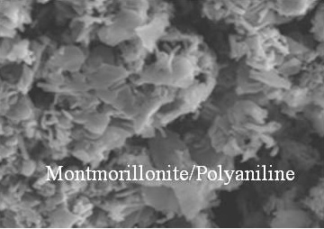
:Polyaniline (PANI) is synthesized in the presence of montmorillonite (Mt). Mt has small spaces between its layers. This interlayer spacing functions as a reaction field for the production of PANI with an organized structure. Mt/PANI composites thus synthesized were characterized by the IR and the UV-Vis optical absorption spectroscopy measurements. Scanning electron microscopy observation showed that the PANI is covered by the flake structure of the Mt. A cylindrical structure was also observed in the sample. X-ray diffraction analysis indicated that the composite of the PANI and the Mt had an ordered structure, suggesting that the macroscopic structure of the natural clays can provide a unique reaction field for polymerization reactions.
1. Introduction
Researchers have recently employed microporous materials to create reaction fields [1,2]. This study suggests that small spaces in materials can effectively function as reaction fields. We recently engaged in liquid crystal (LC) polymerization. Resultant polymers obtained showed that LC-like aggregations form due to transcriptions of the LC matrix. In this report, we carry out polymerization in the presence of montmorillonite (Mt) with a layer structure as a micro-reaction field.
Many studies have been performed on conductive polymers. Polyaniline (PANI) is promising for its low cost and good stability. PANI composites can be prepared in the presence of metals, minerals, and organics [3,4]. Studies on conducting polymer/inorganic layer clay have been conducted [5,6]. Mt is an interesting inorganic clay. Mt consists of layered silicates with negative charges [7,8]. The multiple layers absorb water and organic compounds. Polymerization can be carried out between the layers of Mt, which act as reaction fields [9,10]. Mt can be also used as filler for composite formation.
2. Materials and Methods
2.1. Materials
Aniline was purchased from Wako Chemical (Tokyo, Japan) and purified by distillation. Ammonia/water solution and ammonium persulfate (APS, (NH4)2S2O8) were purchased from Kanto Chemical (Tokyo, Japan), and used as received. Sulfuric acid, N-methyl-2-pyrrolidine (NMP), and methanol were purchased from Nacalai tesque (Tokyo, Japan) and used as received.
2.2. Instruments
Infrared (IR) absorption spectra were obtained with an FT/IR-4600 spectrometer (Jasco, Tokyo, Japan) by the KBr method. UV-Vis absorption spectra were measured with a V-630 UV-Vis optical absorption spectrometer (Jasco, Tokyo, Japan). Electrical conductivity was obtained with a Lowrester-GP and MCP-TP06P probe by the four-probe method (Mitsubishi, Tokyo, Japan). Surface structure of the samples was observed with a JSM-5510 SEM (JEOL, Tokyo, Japan). X-ray diffraction data was obtained with X’pert (PANanalytical, Almelo, The Netherlands). ESR measurement of the solid sample packed into a 5 mm quartz tube was carried out with a JEOL JES TE-200 spectrometer (Tokyo, Japan).
2.3. Preparation of PANI Composites
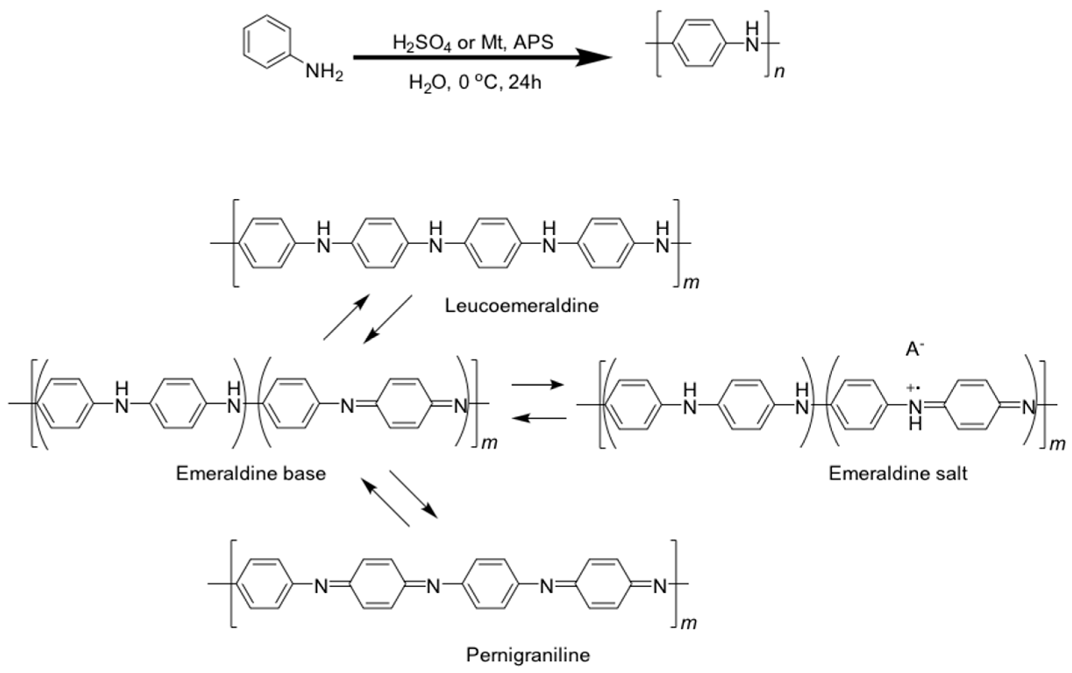
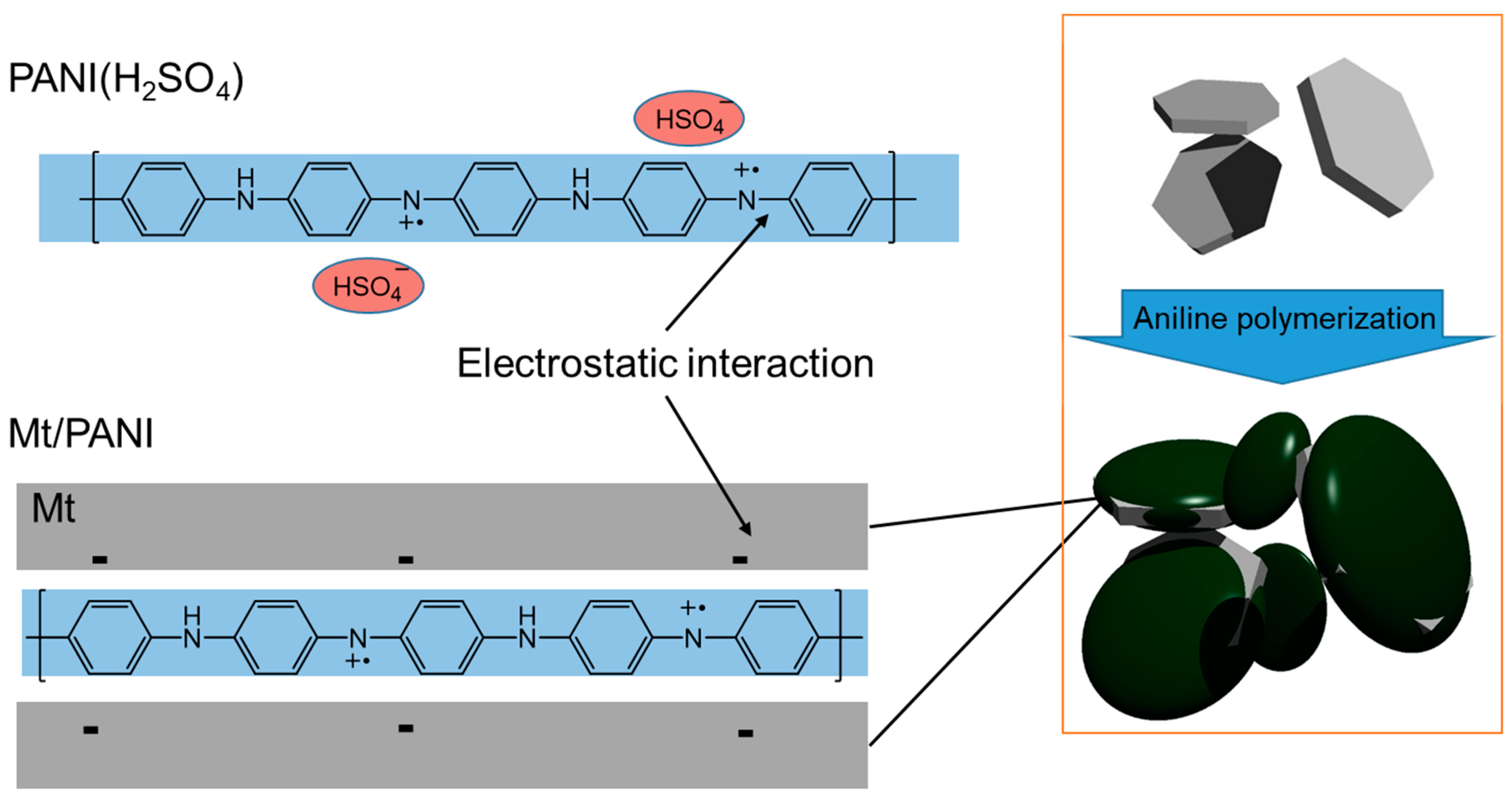
Aniline (0.30 g, 3.2 mmol), montmorillonite (0.3 g, 0.6 g) or sulfuric acid (H2SO4) (0.66g, 6.1 mmol) was added to distilled water (16 mL) in a vial. The solution was stirred and cooled to 0 °C in an ice bath. APS (1.4 g, 6.4 mmol) in distilled water (16 mL) was added to the vial to initiate oxidative polymerization. After 24 h, the solution was washed with a large volume of distilled water and methanol, filtered and dried in a vacuum to obtain product. These composites were abbreviated as Mt/PANI-1 and Mt/PANI-2 (Table 1). Polymerization schemes and PANI structures are shown in Figure 1.
3. Results and Discussion
3.1. FT-IR Absorption Spectra
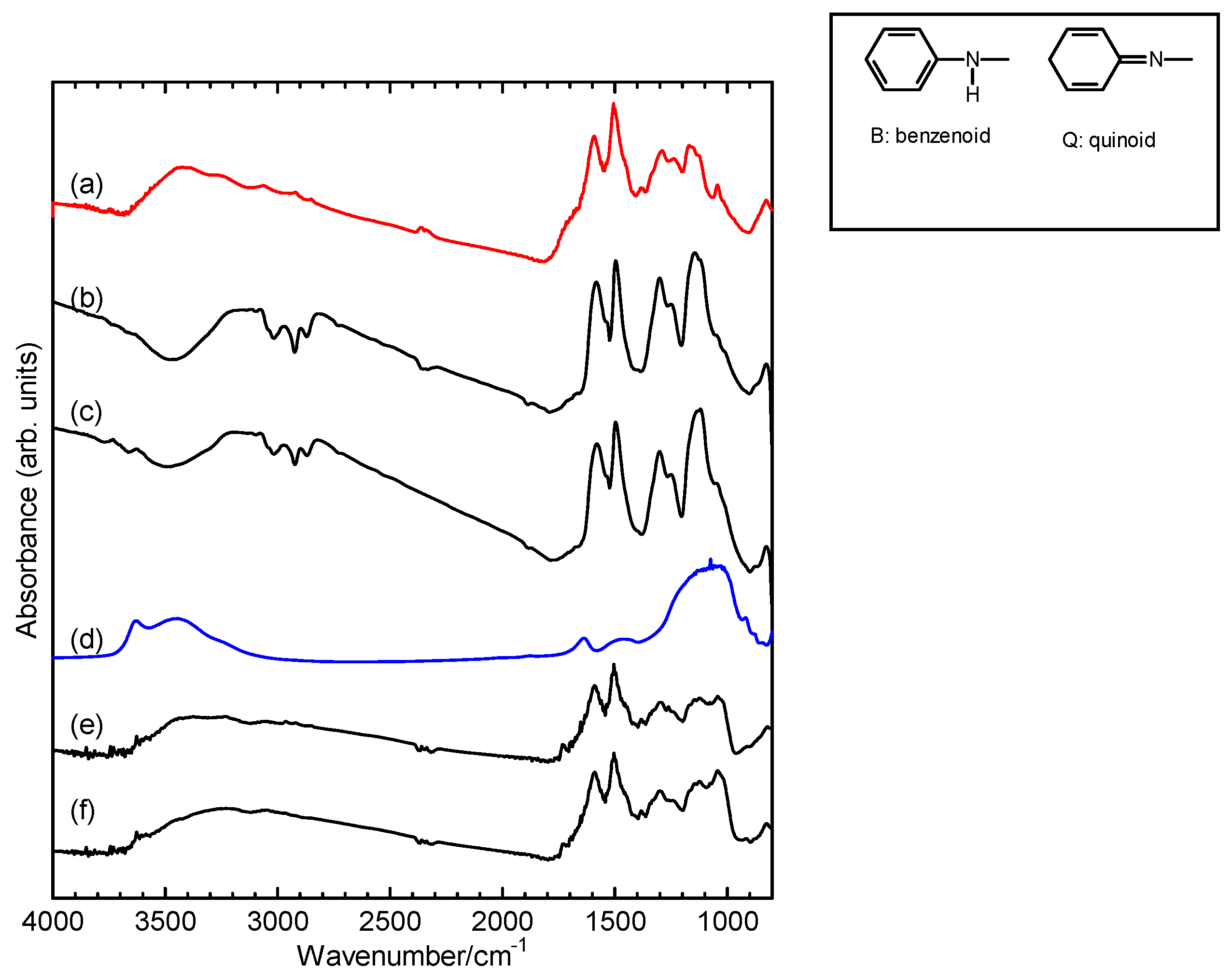
Figure 2 shows IR spectra of the PANI (H2SO4), the Mt, the Mt/PANI composites, and the reduced state samples by ammonia/water. PANI has two aromatic structures in the main chain sequence: benzenoid (B) and quinoid (Q) structures. The PANI has characteristic absorption bands at 1591 cm−1 (N=Q=N stretching, N = nitrogen atom, Q = quinoid structure, B = benzenoid structure, Figure 2 (right), 1506 cm−1 (N–B–N stretching), 1290 cm−1 (B–B–Q stretching), 1230 cm−1 (B–B–B stretching), 1115 cm−1, and 1043 cm−1 (in-plane bending of the 1,4-ring) [13]. The Mt/PANI composites have the same absorption bands as the PANI, but the absorption bands are slightly shifted. The Mt/PANI-1 has absorption bands at 1583 cm−1 (N=Q=N stretching), 1500 cm−1 (N–B–N stretching), 1300 cm−1 (B–B–Q stretching), 1230 cm−1 (B–B–B stretching), 1113 cm−1, and 1038 cm−1 (in-plane bending of the 1,4-ring). The Mt/PANI-2 has absorption bands at 1578 cm−1, 1499 cm−1, 1302 cm−1, 1248 cm−1, 1113 cm−1, and 1045 cm−1. These data are summarized in Table 2. The absorption bands of Mt/PANI-1 and Mt/PANI-2 are slightly shifted toward low wavenumbers. The Mt has a broad absorption band at around 1000–1200 cm−1. These results confirm formation of the composite form.
3.2. UV-Vis Absorption Spectra
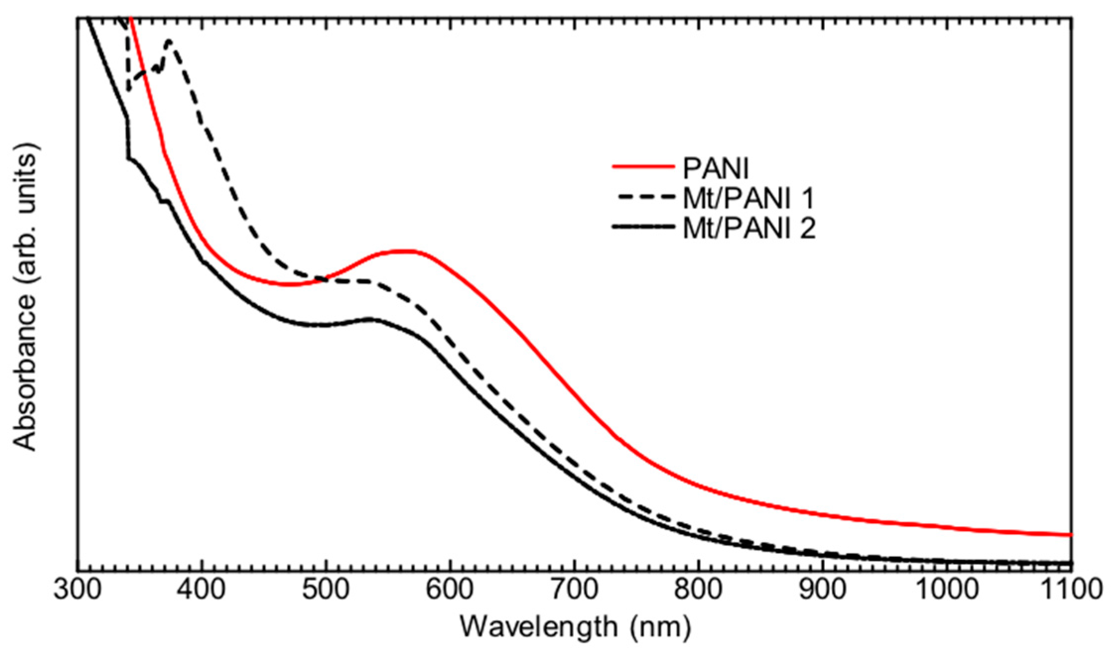
UV-Vis absorption spectra of PANI (H2SO4) and Mt/PANI composites in the NMP solution are shown in Figure 3. The solubility of Mt/PANI is similar to that of PANI, indicating that Mt provides no drawback in solubility. Two characteristic absorption bands appeared for PANI (H2SO4) and the Mt/PANI composites. The absorption bands at 300–400 nm are derived from the π–π* transition of the benzenoid structure of PANI in the main chain [14,15]. The typical absorption bands at 550–600 nm are due to the π–π* transitions of the quinoid structure of the main chain [14,15]. Absorption bands of the Mt/PANI composites, as opposed to those of the pure PANI, were slightly blue-shifted.
3.3. Conductivity
The PANI(H2SO4) and the Mt/PANI composites were pressed into thin pellets and their thicknesses were measured. Next, the electrical conductivity of the samples was measured by the four-probe method. Conductivities of the PANI(H2SO4) and the Mt/PANI composites are summarized in Table 3. The PANI(H2SO4) shows electrical conductivity of 1.5 × 10⁻³ S/cm, Mt/PANI-1 1.6 × 10⁻⁶ S/cm, and Mt/PANI-2 2.1 × 10⁻⁵. A decrease in conductivity is related to the blue shift in the UV-Vis spectroscopy measurement results, and this shift is due to the decrease in the effective conjugation length. The undoped sample showed conductivity of ∼10−10 S/cm, which is low. An electrical interaction between PANI and Mt with negatively charged layers occurred for the undoped sample [16].
3.4. Electron Spin Resonance
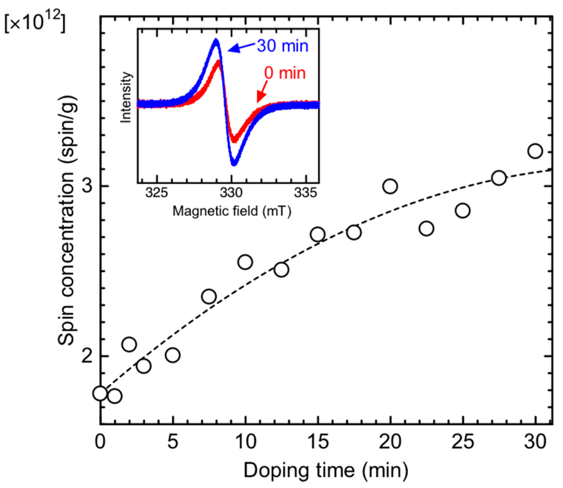
The vapor phase iodine doping process of the Mt/PANI composite was obtained via electron spin resonance (ESR) spectroscopy measurements. The ESR observes unpaired electrons as radicals of polarons (radical cations (charge carriers)). Mt/PANI-2 was treated with ammonia/water to obtain a reduced state (undoped state). However, complete dedoping was not achieved because the sample prior to iodine doping shows the ESR signal. This may be due to the fact that the PANI component in the interlayer of the Mt can not completely contact with ammonia/water in the reduction treatment. Therefore, the sample at 0 min (no doping with iodine) was still partly doped with sulfate ions in the polymerization reaction. The sample was measured at every 2.5 min with iodine doping (Figure 4). The ESR line shapes are a Lorentz-type symmetric form, as shown in the inset of Figure 4. After doping, a radical concentration slowly increased due to the progress of the doping with iodine, confirming that polarons as radical cations were produced in the main chain of the PANI. This result confirms the iodine doping process of Mt/PANI [17].
3.5. SEM Observation
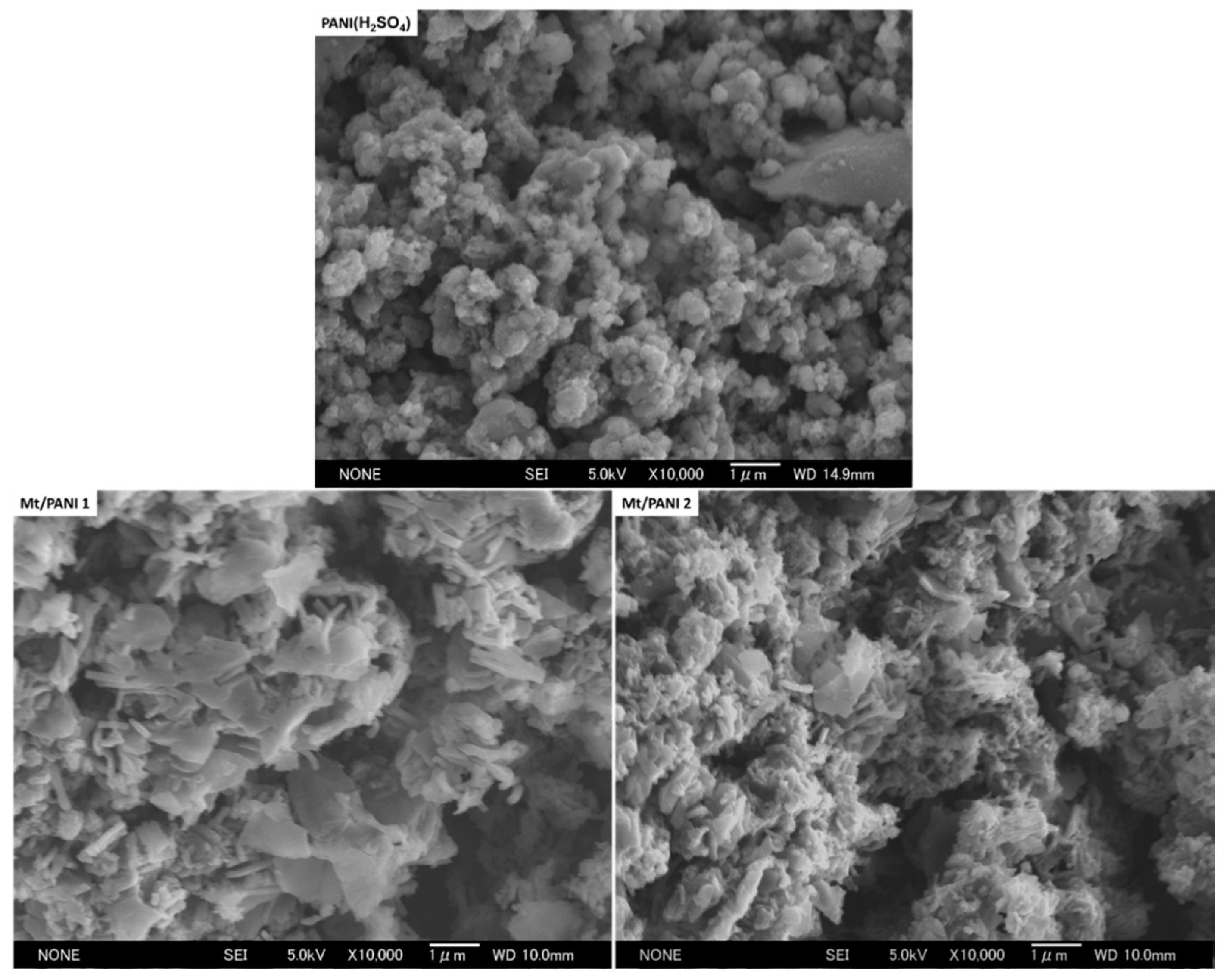
The surface structure of PANI(H2SO4) and Mt/PANI composites were observed via SEM (Figure 5). A bulky structure is often observed when PANI is prepared via chemical oxidative polymerization with sulfuric acid. Mt/PANI composites showed a flake structure [5]. This result implies the occurrence of the self-aggregation of aniline (monomer) in the interlayer of the Mt prior to polymerization. The resultant PANI forms an ordered structure. A cylindrical fiber structure was also observed in the SEM. The structure may be of a hollow fiber form [18,19].
3.6. X-Ray Diffraction
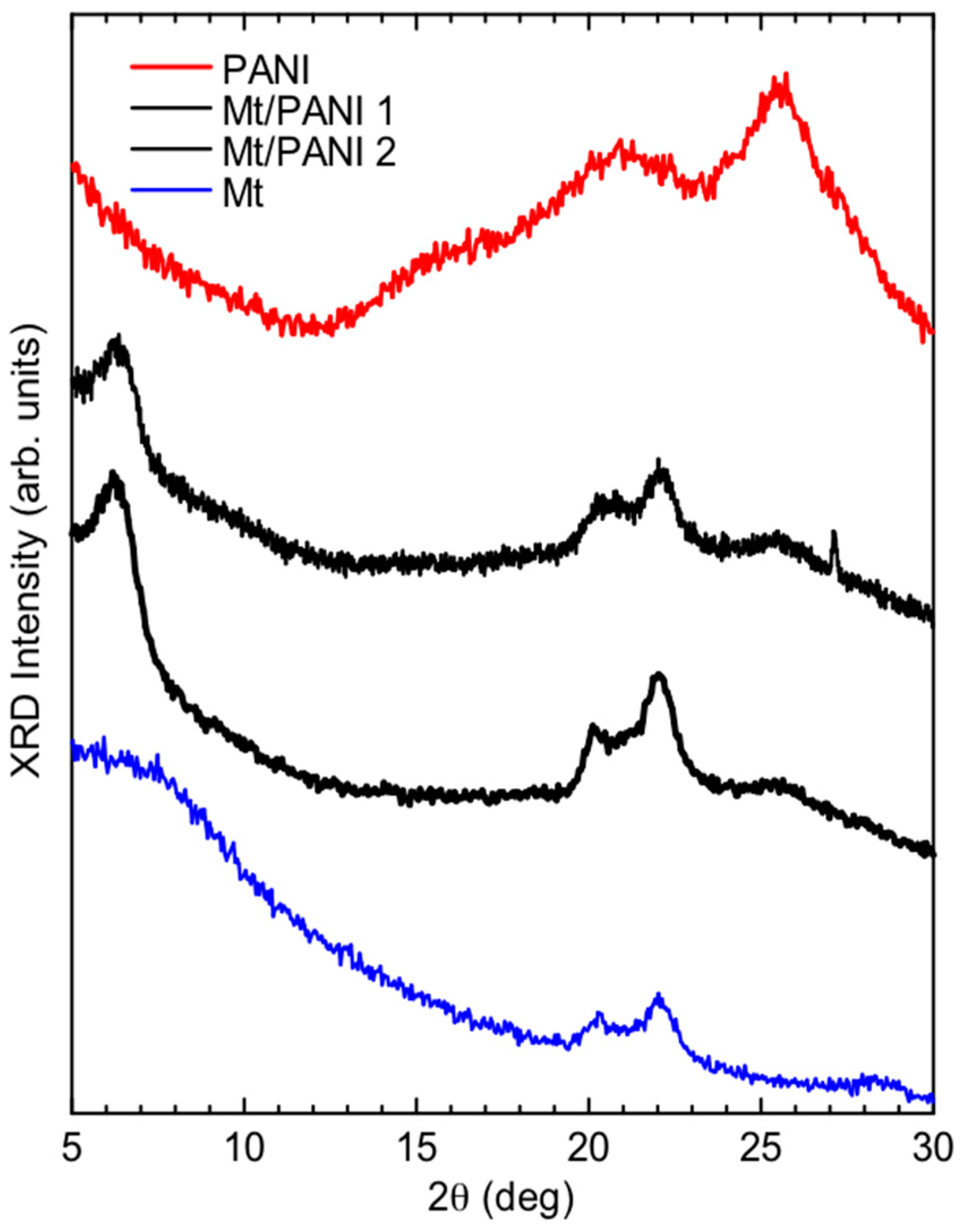
X-ray diffraction results of PANI (H2SO4), montmorillonite, and Mt/PANI composites are shown in Figure 6 and Table 4. PANI exhibits characteristic signals at 2θ = 14.9°, 20.6°, and 25.5° [20,21]. The signals at 2θ = 20.6° and 25.5° were assigned to be (1 1 0) and (2 0 0) of PANI [18]. Mt has diffraction signals at 2θ = 8.0, 20.3°, and 22.2° (4.0Å.). Mt/PANI composites have both signals from the PANI and the Mt, indicating the formation of an inorganic/conducting polymer composite. The signal at 6.2° corresponds to 14 Å. The small distance may be due to the formation of the molecular layer of PANI in the interlayer of Mt. [7,8]. The signal at 6.2° could also cause the formation of a hollow nano-tube [18,19] with good PANI aggregation [20]. Further, polymerization between Mt layers may improve PANI ordering through the interaction of the aniline monomer and Mt layers.
Figure 7 shows the possible polymerization mechanism and resultant structure of PANI/Mt. First, aniline was adsorbed in the Mt layers. Subsequently, the monomers were polymerized in the interlayer to form an ordered polymer.
4. Conclusions
We synthesized PANI in the presence of montmorillonite (Mt). A flake structure of PANI was observed in the SEM images. Mt/PANI composites are expected to have industrial applications, for example, as an anti-corrosion material [22,23]. From a basic viewpoint, the present study found that the macroscopic structure of natural clays provides a unique reaction field that yields the Mt/PANI composite. This composite’s macroscopic form may increase its potential applications.
Acknowledgments
This work was supported by the NIMS microstructural characterization platform as a program of the “Nanotechnology Platform” of the Ministry of Education, Culture, Sports, Science, and Technology (MEXT), Japan.
Author Contributions
Hiromasa Goto conceived and designed the experiments; Kohei Yamabe performed the experiments; Kohei Yamabe and Hiromasa Goto analyzed the data; Kohei Yamabe and Hiromasa Goto wrote the paper.
Conflicts of Interest
The authors declare no conflict of interest.
References
- Miura, S.; Umemura, Y.; Shiratori, Y.; Kitaoka, T. In situ synthesis of Ni/MgO catalysts on inorganic paper-like matrix for methane steam reforming. Chem. Eng. J. 2013, 229, 515–521. [Google Scholar] [CrossRef]
- Kitaoka, T. New frontier of paper-structured catalysts. J. Soc. Fiber Sci. Technol. 2018, 74, 16–19. [Google Scholar] [CrossRef]
- Detsi, E.; Onck, P.; De Hosson, J.T.M. Metallic muscles at work: High rate actuation in nanoporous gold/polyaniline composites. ACS Nano 2013, 7, 4299–4306. [Google Scholar] [CrossRef] [PubMed]
- Kawashima, H.; Goto, H. Preparation and properties of polyaniline in the presence of trehalose. Soft Nanosci. Lett. 2011, 1, 71–75. [Google Scholar]
- Tran, X.T.; Park, S.S.; Hussain, M.; Kim, H.T. Electroconductive and catalytic performance of polypyrrole/montmorillonite/silver composites synthesized through in situ oxidative polymerization. J. Appl. Polym. Sci. 2018, 135, 45986. [Google Scholar] [CrossRef]
- Olad, A.; Amini, M.; Rashidzadeh, A. Electrodeposition of homogeneous and adherent polypyrrole/Na+-cloisite nanocomposite on iron electrodes. Fibers Polym. 2012, 13, 475–480. [Google Scholar] [CrossRef]
- Lee, D.; Char, K.; Lee, S.W.; Park, Y.W. Structural changes of polyaniline/montmorillonite nanocomposites and their effects on physical properties. J. Mater. Chem. 2003, 13, 2942–2947. [Google Scholar] [CrossRef]
- Kazim, S.; Ahmad, S.; Pfleger, J.; Plestil, J.; Joshi, Y.M. Polyaniline–sodium montmorillonite clay nanocomposites: Effect of clay concentration on thermal, structural, and electrical properties. J. Mater. Sci. 2012, 47, 420–428. [Google Scholar] [CrossRef]
- Do Nascimento, G.M.; Constantino, V.R.L.; Landers, R.; Temperini, M.L.A. Spectroscopic characterization of polyaniline formed in the presence of montmorillonite clay. Polymer 2006, 47, 6131–6139. [Google Scholar] [CrossRef]
- Do Nascimento, G.M.; Constantino, V.R.L.; Temperini, M.L.A. Spectroscopic characterization of a new type of conducting polymer—Clay nanocomposite. Macromolecules 2002, 35, 7535–7537. [Google Scholar] [CrossRef]
- Mo, Z.; Zhang, C.; Zhao, G.; Zhang, P.; Wu, Y. Sonochemistry synthesis of lanthanum ions-doped polyaniline/montmorillonite nanocomposites and their conductivity and thermostability characterization. Asian J. Chem. 2015, 27, 467–472. [Google Scholar]
- Olad, A.; Azhar, F.F. Eco-friendly biopolymer/clay/conducting polymer nanocomposite: Characterization and its application in reactive dye removal. Fibers Polym. 2014, 15, 1321–1329. [Google Scholar] [CrossRef]
- Tang, J.; Jing, X.; Wang, B.; Wang, F. Infrared spectra of soluble polyaniline. Synth. Met. 1988, 24, 231–238. [Google Scholar] [CrossRef]
- Norris, I.D.; Shaker, M.M.; Ko, F.K.; MacDiarmid, A.G. Electrostatic fabrication of ultrafine conducting fibers: Polyaniline/polyethylene oxide blends. Synth. Met. 2000, 114, 109–114. [Google Scholar] [CrossRef]
- Pruneanu, S.; Veress, E.; Marian, I.; Oniciu, L. Characterization of polyaniline by cyclic voltammetry and UV-Vis absorption spectroscopy. J. Mater. Sci. 1999, 34, 2733–2739. [Google Scholar] [CrossRef]
- MacDiarmid, A.G. Synthetic metals. Angew. Chem. Int. Edit. 2001, 40, 2581–2590. [Google Scholar] [CrossRef]
- Goto, H. A possibility for construction of an iodine cleaning system based on doping for π-conjugated polymers. Polymers 2011, 3, 875–885. [Google Scholar] [CrossRef]
- Hopkins, A.R.; Lipeles, R.A.; Hwang, S.J. Morphology characterization of polyaniline nano-and microstructures. Synth. Met. 2008, 158, 594–601. [Google Scholar] [CrossRef]
- Zhang, Z.; Wei, Z.; Wan, M. Nanostructures of polyaniline doped with inorganic acids. Macromolecules 2002, 35, 5937–5942. [Google Scholar] [CrossRef]
- Sanches, E.A.; Soares, J.C.; Mafud, A.C.; Fernandes, E.G.R.; Leite, F.L.; Mascarenhas, Y.P. Structural characterization of chloride salt of conducting polyaniline obtained by XRD, SAXD, SAXS and SEM. J. Mol. Struct. 2013, 1036, 121–126. [Google Scholar] [CrossRef]
- Xia, Y.; Wiesinger, J.M.; MacDiarmid, A.G.; Epstein, A.J. Camphorsulfonic acid fully doped polyaniline emeraldine salt: Conformations in different solvents studied by an ultraviolet/visible/near-infrared spectroscopic method. Chem. Mater. 1995, 7, 443–445. [Google Scholar] [CrossRef]
- Chang, K.C.; Lai, M.C.; Peng, C.W.; Chen, Y.T.; Yeh, J.M.; Lin, C.L.; Yang, J.C. Comparative studies on the corrosion protection effect of DBSA-doped polyaniline prepared from in situ emulsion polymerization in the presence of hydrophilic Na+-MMT and organophilic organo-MMT clay platelets. Electrochim. Acta 2006, 51, 5645–5653. [Google Scholar] [CrossRef]
- Yeh, J.M.; Liou, S.J.; Lai, C.Y.; Wu, P.C.; Tsai, T.Y. Enhancement of corrosion protection effect in polyaniline via the formation of polyaniline—Clay nanocomposite materials. Chem. Mater. 2001, 13, 1131–1136. [Google Scholar] [CrossRef]
Figure 1.
Chemical structures of polyaniline (PANI).

Figure 2.
FT-IR spectra of Mt/PANI composites. (a): PANI(H2SO4) (pure PANI). (b): Mt/PANI-1. (c): Mt/PANI-2. (d): Mt. (e): Mt/PANI-1 (reduced). (f): Mt/PANI-2 (reduced). Mt = Montmorillonite. PANI = polyaniline.
Figure 2.
FT-IR spectra of Mt/PANI composites. (a): PANI(H2SO4) (pure PANI). (b): Mt/PANI-1. (c): Mt/PANI-2. (d): Mt. (e): Mt/PANI-1 (reduced). (f): Mt/PANI-2 (reduced). Mt = Montmorillonite. PANI = polyaniline.

Figure 3.
UV-Vis absorption spectra of Mt/PANI composites in N-methyl-2-pyrrolidine (NMP).

Figure 4.
In situ electron spin resonance (ESR) spectroscopy measurement of Mt/PANI with vapor phase doping of iodine. Inset shows the ESR signal shape of the Mt/PANI prior to iodine doping (0 min) and after doping (30 min).
Figure 4.
In situ electron spin resonance (ESR) spectroscopy measurement of Mt/PANI with vapor phase doping of iodine. Inset shows the ESR signal shape of the Mt/PANI prior to iodine doping (0 min) and after doping (30 min).

Figure 5.
Scanning electron microscopy (SEM) images of PANI and Mt/PANI composites.

Figure 6.
X-ray diffraction (XRD) of PANI, Mt, and Mt/PANI composites.

Figure 7.
Possible polymerization of aniline between Mt layers.


Table 1.
Preparation of montmorillonite (Mt)/PANI composites.
| Aniline (mg) | Montmorillonite (mg) | H2SO4 (mg) | APS (g) | Water (mL) | |
|---|---|---|---|---|---|
| PANI(H2SO4) 1 | 300 | - | 660 | 1.4 | 32 |
| Mt/PANI-1 | 300 | 300 | - | 1.4 | 32 |
| My/PANI-2 | 300 | 600 | - | 1.4 | 32 |
1 Pure polyaniline.
Table 2.
IR absorption bands of Mt/PANI composites.
| PANI | Mt/PANI-1 | Mt/PANI-2 | Mt | Mt/PANI-1 (reduced) | Mt/PANI-2 (reduced) | |
|---|---|---|---|---|---|---|
| N=Q=N | 1591 | 1583 | 1578 | - | 1589 | 1590 |
| N–B–N | 1506 | 1500 | 1499 | - | 1504 | 1504 |
| B–B–Q | 1290 | 1300 | 1302 | - | 1293 | 1301 |
| B–B–B | 1230 | 1230 | 1248 | - | 1262 | 1243 |
| in-plane bending of the 1,4-ring | 1115, 1043 | 1113, 1038 | 1113, 1045 | - | 1123, 1042 | 1133, 1043 |
| Mt | - | ○ | ○ | ○ | ○ | ○ |
Table 3.
Electrical conductivities of Mt/PANI films.
| Samples | Conductivity (S/cm) |
|---|---|
| PANI(H2SO4) | 1.6 × 10⁻³ |
| Mt/PANI-1 | 1.5 × 10⁻⁶ |
| Mt/PANI-2 | 2.1 × 10⁻⁵ |
Table 4.
XRD 2θ data (°) of PANI, Mt, and Mt/PANI composites.
| Samples | Diffraction Positions | |||||
|---|---|---|---|---|---|---|
| 1 | 2 | 3 | 4 | 5 | 6 | |
| PANI | - | - | 14.9 | 20.6 | - | 25.5 |
| Mt | 8.0 | - | 20.3 | 22.2 | - | |
| Mt/PANI-1 | 6.2 | - | - | 20.3 | 22.2 | 25.5 |
| Mt/PANI-2 | 6.2 | - | - | 20.3 | 22.2 | 25.5 |
© 2018 by the authors. Licensee MDPI, Basel, Switzerland. This article is an open access article distributed under the terms and conditions of the Creative Commons Attribution (CC BY) license (http://creativecommons.org/licenses/by/4.0/).
Share and Cite
MDPI and ACS Style
Yamabe, K.; Goto, H. Synthesis and Surface Observation of Montmorillonite/Polyaniline Composites. J. Compos. Sci. 2018, 2, 15. https://doi.org/10.3390/jcs2010015
AMA Style
Yamabe K, Goto H. Synthesis and Surface Observation of Montmorillonite/Polyaniline Composites. Journal of Composites Science. 2018; 2(1):15. https://doi.org/10.3390/jcs2010015
Chicago/Turabian StyleYamabe, Kohei, and Hiromasa Goto. 2018. "Synthesis and Surface Observation of Montmorillonite/Polyaniline Composites" Journal of Composites Science 2, no. 1: 15. https://doi.org/10.3390/jcs2010015