Fabrication of Three-Dimensional Composite Scaffold for Simultaneous Alveolar Bone Regeneration in Dental Implant Installation

 , ,
, , 
Abstract
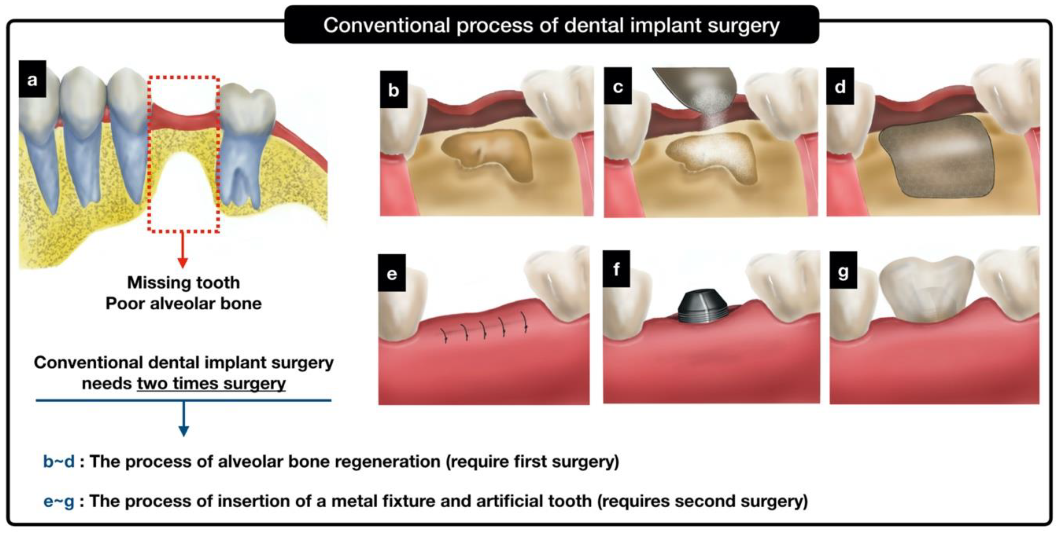
:1. Introduction
2. Results
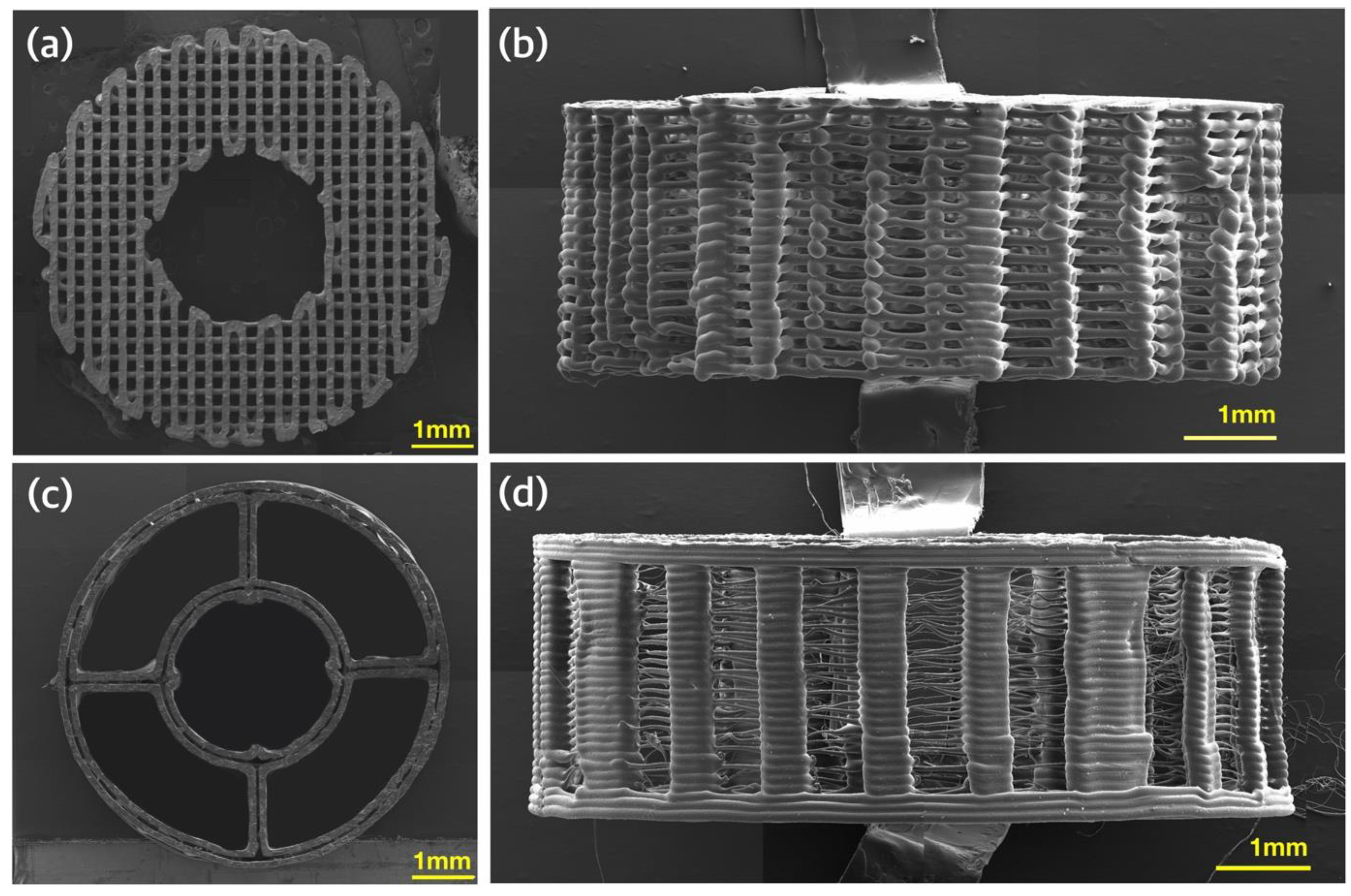
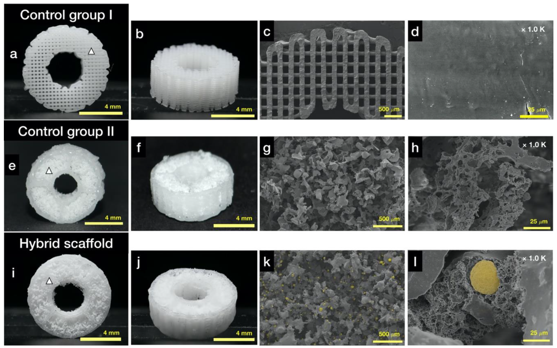
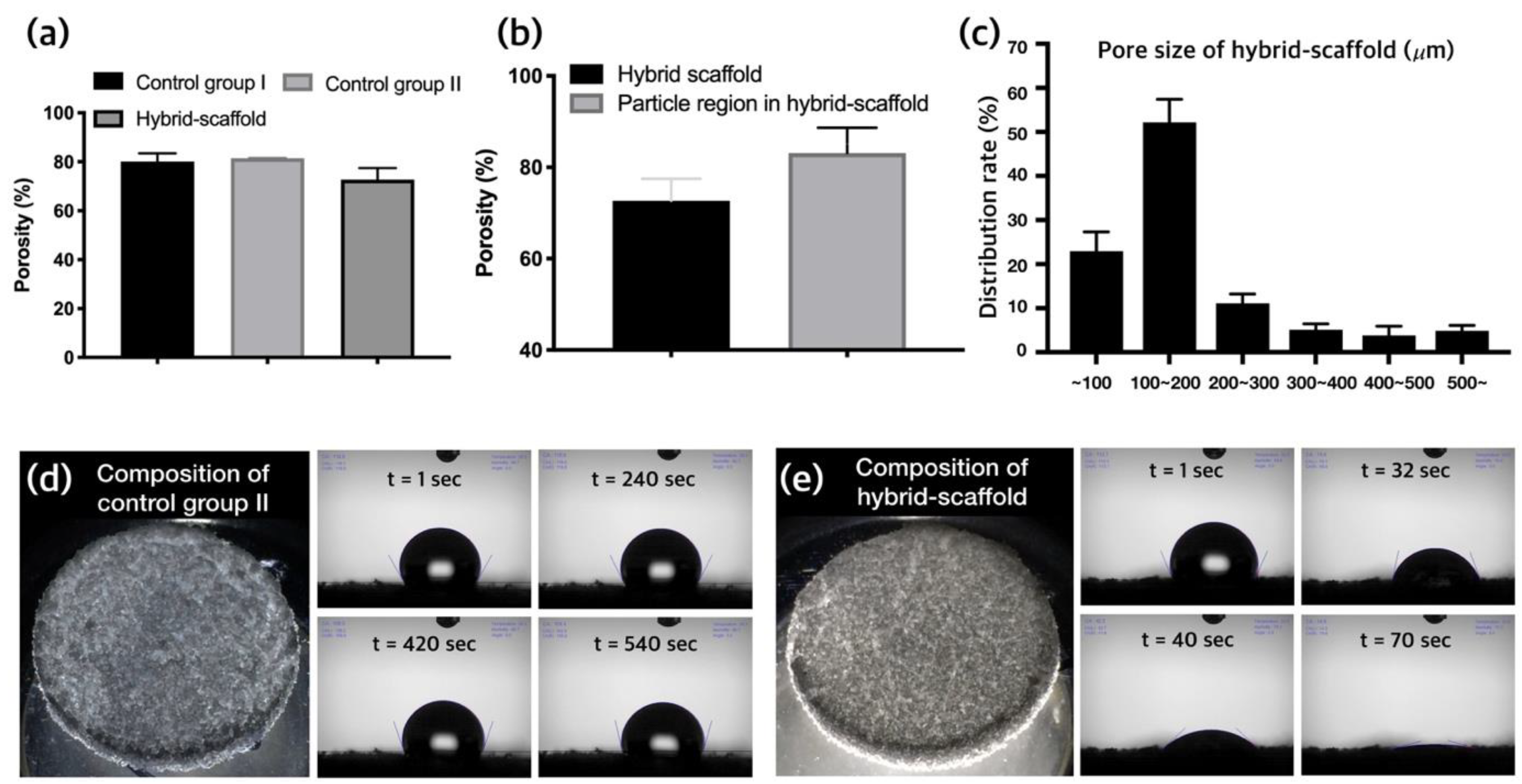
2.1. Morphology Analysis of the Fabricated Hybrid Scaffold
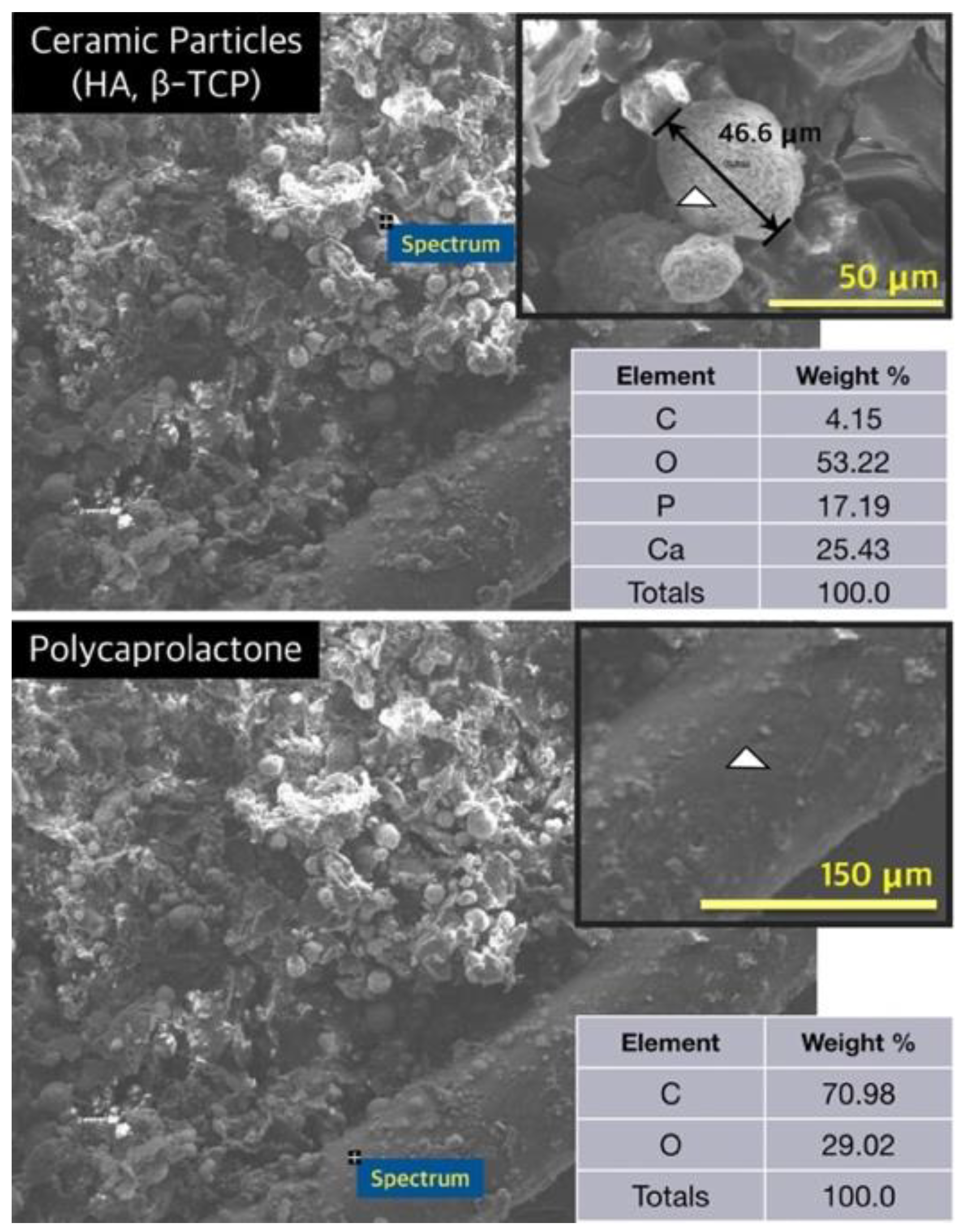
2.2. Characteristics of the Fabricated Hybrid Scaffold
2.3. Assessment of Water Absorption in the Hybrid Scaffold
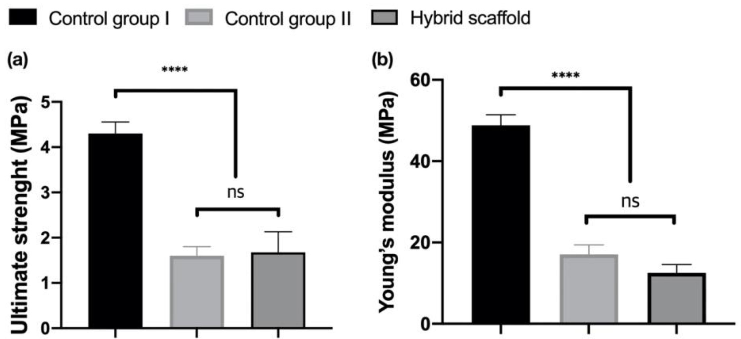
2.4. Mechanical Property Analysis
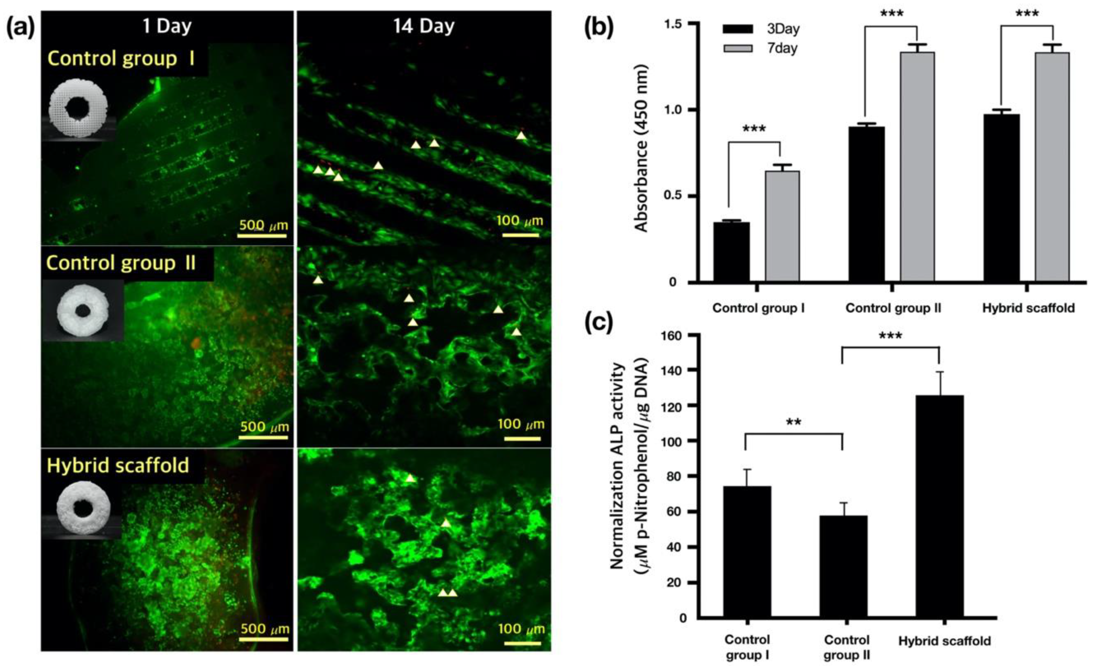
2.5. In Vitro Cell Viability and Proliferation
2.5.1. Live and Dead Assays
2.5.2. Cell Proliferation
2.5.3. ALP Activity of Saos-2 Cells
3. Discussion
4. Materials and Methods
4.1. Materials
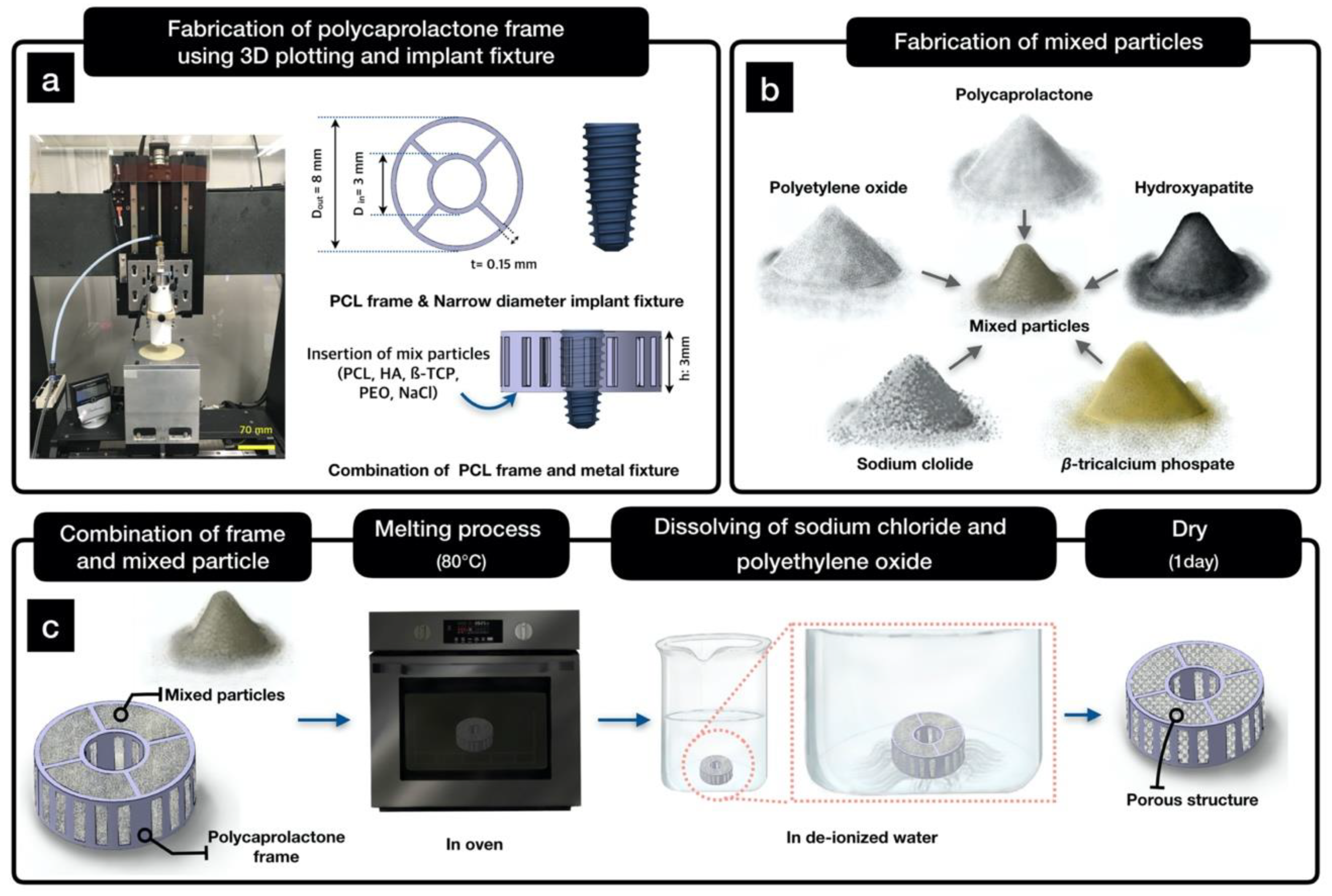
4.2. Design of the Hybrid Scaffold
4.3. Fabrication of a PCL Frame Using 3D Printing
4.4. Fabrication of a Hybrid Scaffold Using Mixed Particles
4.5. Characterization of the Fabricated Hybrid Scaffold
4.6. Compressive Test
4.7. In Vitro Cell Characterisrics
4.7.1. Cell Culture
4.7.2. Live and Dead Assays
4.7.3. Cell Proliferation Assay
4.7.4. Alkaline Phosphatase Assay
4.8. Statistical Analysis
5. Conclusions
Author Contributions
Funding
Conflicts of Interest
Abbreviations
| PCL | polycaprolactone |
| PEO | polyethylene oxide |
| HA | hydroxyapatite |
| β-TCP | β-tricalcium phosphate |
| NaCl | sodium chloride |
| SLUP | salt leaching using particles |
| ALP | alkaline phosphatase assay |
| PBS | phosphate-buffered saline |
References
- Chiapasco, M.; Zaniboni, M. Clinical outcomes of GBR procedures to correct peri-implant dehiscences and fenestrations: A systematic review. Clin. Oral Implan. Res. 2009, 20, 113–123. [Google Scholar] [CrossRef]
- Von Stein-Lausnitz, M.; Nickenig, H.J.; Wolfart, S.; Neumann, K.; Von Stein-Lausnitz, A.; Spies, B.C.; Beuer, F. Survival rates and complication behaviour of tooth implant-supported, fixed dental prostheses: A systematic review and meta-analysis. J. Dent. 2019, 88, 103167. [Google Scholar] [CrossRef]
- Pjetursson, B.E.; Thoma, D.; Jung, R.; Zwahlen, M.; Zembic, A. A systematic review of the survival and complication rates of implant-supported fixed dental prostheses (FDPs) after a mean observation period of at least 5 years. Clin. Oral Implan. Res. 2012, 23, 22–38. [Google Scholar] [CrossRef]
- Bergermann, M.; Donald, P.J.; aWengen, D.F. Screwdriver aspiration. A complication of dental implant placement. Int. J. Oral Maxillofac Surg. 1992, 21, 339–341. [Google Scholar] [CrossRef]
- Wittneben, J.G.; Buser, D.; Salvi, G.E.; Burgin, W.; Hicklin, S.; Bragger, U. Complication and failure rates with implant-supported fixed dental prostheses and single crowns: A 10-year retrospective study. Clin. Implant. Dent. Relat. Res. 2014, 16, 356–364. [Google Scholar] [CrossRef] [PubMed]
- Bauer, T.W.; Muschler, G.F. Bone graft materials—An overview of the basic science. Clin. Orthop. Relat. R 2000, 371, 10–27. [Google Scholar] [CrossRef]
- Burg, K.J.L.; Porter, S.; Kellam, J.F. Biomaterial developments for bone tissue engineering. Biomaterials 2000, 21, 2347–2359. [Google Scholar] [CrossRef]
- Kim, Y.-K.; Lee, J.K.; Kim, K.-W.; Um, I.-W.; Murata, M. Healing Mechanism and Clinical Application of Autogenous Tooth Bone Graft Material. Adv. Biomater. Sci. Biomed. Appl. 2013. [Google Scholar] [CrossRef]
- Forero, J.C.; Roa, E.; Reyes, J.G.; Acevedo, C.; Osses, N. Development of Useful Biomaterial for Bone Tissue Engineering by Incorporating Nano-Copper-Zinc Alloy (nCuZn) in Chitosan/Gelatin/Nano-Hydroxyapatite (Ch/G/nHAp) Scaffold. Materials 2017, 10, 1177. [Google Scholar] [CrossRef] [Green Version]
- Beaman, F.D.; Bancroft, L.W.; Peterson, J.J.; Kransdorf, M.J. Bone graft materials and synthetic substitutes. Radiol. Clin. 2006, 44, 451–461. [Google Scholar] [CrossRef]
- Goldberg, V.M. Bone grafts and their substitutes: Facts, fiction, and futures. Orthopedics 2001, 24, 875–876. [Google Scholar] [PubMed]
- Greenwald, A.S.; Boden, S.D.; Goldberg, V.M.; Khan, Y.; Laurencin, C.T.; Rosier, R.N.; Implants, C.B. Bone-graft substitutes: Facts, fictions, and applications. J. Bone Joint Surg. Am. 2001, 83a, 98–103. [Google Scholar] [CrossRef] [PubMed]
- Kim, Y.K. Clinical application and classification of bone graft material according to component. J. Korean Dent. Assoc. 2010, 48, 263–274. [Google Scholar]
- McCreadie, B.R.; Morris, M.D.; Chen, T.C.; Rao, D.S.; Finney, W.F.; Widjaja, E.; Goldstein, S.A. Bone tissue compositional differences in women with and without osteoporotic fracture. Bone 2006, 39, 1190–1195. [Google Scholar] [CrossRef] [PubMed]
- Penel, G.; Delfosse, C.; Descamps, M.; Leroy, G. Composition of bone and apatitic biomaterials as revealed by intravital Raman microspectroscopy. Bone 2005, 36, 893–901. [Google Scholar] [CrossRef]
- Malmberg, P.; Nygren, H. Methods for the analysis of the composition of bone tissue, with a focus on imaging mass spectrometry (TOF-SIMS). Proteomics 2008, 8, 3755–3762. [Google Scholar] [CrossRef]
- Jun, C.M.; Yun, J.-H. Three-Dimensional Bone Regeneration of Alveolar Ridge Defects Using Corticocancellous Allogeneic Block Grafts: Histologic and Immunohistochemical Analysis. Int. J. Periodontics Restor. Dent. 2016, 36, 75–81. [Google Scholar] [CrossRef] [Green Version]
- Hwang, J.W.; Park, J.S.; Lee, J.S.; Jung, U.W.; Kim, C.S.; Cho, K.S.; Lee, Y.K.; Choi, S.H. Comparative evaluation of three calcium phosphate synthetic block bone graft materials for bone regeneration in rabbit calvaria. J. Biomed. Mater. Res. B 2012, 100b, 2044–2052. [Google Scholar] [CrossRef]
- Veis, A.; Dabarakis, N.; Koutrogiannis, C.; Barlas, I.; Petsa, E.; Romanos, G. Evaluation of Vertical Bone Regeneration Using Block and Particulate Forms of Bio-Oss Bone Graft: A Histologic Study in the Rabbit Mandible. J. Oral Implant. 2015, 41, E66–E72. [Google Scholar] [CrossRef]
- Kim, Y.K.; Pang, K.M.; Yun, P.Y.; Leem, D.H.; Um, I.W. Long-term follow-up of autogenous tooth bone graft blocks with dental implants. Clin. Case Rep. 2017, 5, 108–118. [Google Scholar] [CrossRef] [Green Version]
- Lee, J.S.; Park, W.Y.; Cha, J.K.; Jung, U.W.; Kim, C.S.; Lee, Y.K.; Choi, S.H. Periodontal tissue reaction to customized nano-hydroxyapatite block scaffold in one-wall intrabony defect: A histologic study in dogs. J. Periodontal Implant. Sci. 2012, 42, 50–58. [Google Scholar] [CrossRef] [PubMed]
- Kim, Y.K.; Yun, P.Y.; Um, I.W.; Lee, H.J.; Yi, Y.J.; Bae, J.H.; Lee, J. Alveolar ridge preservation of an extraction socket using autogenous tooth bone graft material for implant site development: Prospective case series. J. Adv. Prosthodont 2014, 6, 521–527. [Google Scholar] [CrossRef] [PubMed] [Green Version]
- Matsuura, T.; Akizuki, T.; Hoshi, S.; Ikawa, T.; Kinoshita, A.; Sunaga, M.; Oda, S.; Kuboki, Y.; Izumi, Y. Effect of a tunnel-structured beta-tricalcium phosphate graft material on periodontal regeneration: A pilot study in a canine one-wall intrabony defect model. J. Periodontal Res. 2015, 50, 347–355. [Google Scholar] [CrossRef] [PubMed]
- Ducheyne, P.; Qiu, Q. Bioactive ceramics: The effect of surface reactivity on bone formation and bone cell function. Biomaterials 1999, 20, 2287–2303. [Google Scholar] [CrossRef]
- Kelly, C.M.; Wilkins, R.M.; Gitelis, S.; Hartjen, C.; Watson, J.T.; Kim, P.T. The use of a surgical grade calcium sulfate as a bone graft substitute—Results of a multicenter trial. Clin. Orthop. Relat. R 2001, 382, 42–50. [Google Scholar] [CrossRef]
- Mirzayan, R.; Panossian, V.; Avedian, R.; Forrester, D.M.; Menendez, L.R. The use of calcium sulfate in the treatment of benign bone lesions—A preliminary report. J. Bone Joint Surg. Am. 2001, 83a, 355–358. [Google Scholar] [CrossRef]
- Tay, B.K.B.; Patel, V.V.; Bradford, D.S. Calcium sulfate-and calcium phosphate-based bone substitutes—Mimicry of the mineral phase of bone. Orthop. Clin. N Am. 1999, 30, 615. [Google Scholar] [CrossRef]
- Park, S.A.; Lee, S.H.; Kim, W.D. Fabrication of porous polycaprolactone/hydroxyapatite (PCL/HA) blend scaffolds using a 3D plotting system for bone tissue engineering. Bioproc. Biosyst. Eng. 2011, 34, 505–513. [Google Scholar] [CrossRef]
- Shor, L.; Guceri, S.; Wen, X.J.; Gandhi, M.; Sun, W. Fabrication of three-dimensional polycaprolactone/hydroxyapatite tissue scaffolds and osteoblast-scaffold interactions in vitro. Biomaterials 2007, 28, 5291–5297. [Google Scholar] [CrossRef]
- Wiria, F.E. Poly-e-caprolactone/hydroxyapatite for tissue engineering scaffold fabrication via selective laser sintering. Acta Biomater. 2007, 3, 1–12. [Google Scholar] [CrossRef]
- Milazzo, M.; Negrini, N.C.; Scialla, S.; Marelli, B.; Fare, S.; Danti, S.; Buehler, M. Additive Manufacturing Approaches for Hydroxyapatite-Reinforced Composites. Adv. Funct. Mater. 2019, 29. [Google Scholar] [CrossRef] [Green Version]
- Kim, H.W.; Lee, E.J.; Kim, H.E.; Salih, V.; Knowles, J.C. Effect of fluoridation of hydroxyapatite in hydroxyapatite-polycaprolactone composites on osteoblast activity. Biomaterials 2005, 26, 4395–4404. [Google Scholar] [CrossRef] [PubMed]
- D’Alessandro, D.; Perale, G.; Milazzo, M.; Moscato, S.; Stefanini, C.; Pertici, G.; Danti, S. Bovine bone matrix/poly(L-lactic-co-epsilon-caprolactone)/gelatin hybrid scaffold (SmartBone (R)) for maxillary sinus augmentation: A histologic study on bone regeneration. Int. J. Pharmaceut. 2017, 523, 534–544. [Google Scholar] [CrossRef] [PubMed] [Green Version]
- McCracken, M. Dental implant materials: Commercially pure titanium and titanium alloys. J. Prosthodont 1999, 8, 40–43. [Google Scholar] [CrossRef]
- Rahmitasari, F.; Ishida, Y.; Kurahashi, K.; Matsuda, T.; Watanabe, M.; Ichikawa, T. PEEK with Reinforced Materials and Modifications for Dental Implant Applications. Dent. J. 2017, 5, 35. [Google Scholar] [CrossRef] [Green Version]
- Nueesch, R.; Conejo, J.; Mante, F.; Fischer, J.; Martin, S.; Rohr, N.; Blatz, M.B. Loading capacity of CAD/CAM-fabricated anterior feldspathic ceramic crowns bonded to one-piece zirconia implants with different cements. Clin. Oral Implan. Res. 2019, 30, 178–186. [Google Scholar] [CrossRef]
- Cho, Y.S.; Hong, M.W.; Quan, M.; Kim, S.Y.; Lee, S.H.; Lee, S.J.; Kim, Y.Y.; Cho, Y.S. Assessments for bone regeneration using the polycaprolactone SLUP (salt-leaching using powder) scaffold. J. Biomed. Mater. Res. Part A 2017, 105, 3432–3444. [Google Scholar] [CrossRef]
- Jeong, H.J.; Gwak, S.J.; Kang, N.U.; Hong, M.W.; Kim, Y.Y.; Cho, Y.S.; Lee, S.J. Bioreactor mimicking knee-joint movement for the regeneration of tissue-engineered cartilage. J. Mech. Sci. Technol. 2019, 33, 1841–1850. [Google Scholar] [CrossRef]
- Zhang, Y.C.; Sun, H.W.; Song, X.F.; Gu, X.L.; Sun, C.Y. Biomaterials for Periodontal Tissue Regeneration. Rev. Adv. Mater. Sci. 2015, 40, 209–214. [Google Scholar]
- Wu, T.; Shi, H.; Liang, Y.; Lu, T.; Lin, Z.; Ye, J. Improving osteogenesis of calcium phosphate bone cement by incorporating with manganese doped β-tricalcium phosphate. Mater. Sci. Eng. C 2020, 109. [Google Scholar] [CrossRef]
- Ryu, H.-S.; Hong, K.S.; Chang, B.-S.; Lee, C.-K.; Chung, S.-S. An improvement in sintering property of b-tricalcium phosphate by addition of calcium pyrophosphate. Biomaterials 2002, 23. [Google Scholar] [CrossRef]
- Cho, Y.S.; Hong, M.W.; Kim, S.Y.; Lee, S.J.; Lee, J.H.; Kim, Y.Y.; Cho, Y.S. Fabrication of dual-pore scaffolds using SLUP (salt leaching using powder) and WNM (wire-network molding) techniques. Mat. Sci. Eng. C 2014, 45, 546–555. [Google Scholar] [CrossRef] [PubMed]


© 2020 by the authors. Licensee MDPI, Basel, Switzerland. This article is an open access article distributed under the terms and conditions of the Creative Commons Attribution (CC BY) license (http://creativecommons.org/licenses/by/4.0/).
Share and Cite
Jeong, H.-J.; Gwak, S.-J.; Seo, K.D.; Lee, S.; Yun, J.-H.; Cho, Y.-S.; Lee, S.-J. Fabrication of Three-Dimensional Composite Scaffold for Simultaneous Alveolar Bone Regeneration in Dental Implant Installation. Int. J. Mol. Sci. 2020, 21, 1863. https://doi.org/10.3390/ijms21051863
Jeong H-J, Gwak S-J, Seo KD, Lee S, Yun J-H, Cho Y-S, Lee S-J. Fabrication of Three-Dimensional Composite Scaffold for Simultaneous Alveolar Bone Regeneration in Dental Implant Installation. International Journal of Molecular Sciences. 2020; 21(5):1863. https://doi.org/10.3390/ijms21051863
Chicago/Turabian StyleJeong, Hun-Jin, So-Jung Gwak, Kyoung Duck Seo, SaYa Lee, Jeong-Ho Yun, Young-Sam Cho, and Seung-Jae Lee. 2020. "Fabrication of Three-Dimensional Composite Scaffold for Simultaneous Alveolar Bone Regeneration in Dental Implant Installation" International Journal of Molecular Sciences 21, no. 5: 1863. https://doi.org/10.3390/ijms21051863