IFC Schemas in ISO/TC 211 Compliant UML for Improved Interoperability between BIM and GIS


1
Norwegian Public Roads Administration, 2318 Hamar, Norway
2
Department of Manufacturing and Civil Engineering, Norwegian University of Science and Technology, 2821 Gjøvik, Norway
*
Author to whom correspondence should be addressed.
ISPRS Int. J. Geo-Inf. 2020, 9(4), 278; https://doi.org/10.3390/ijgi9040278
Submission received: 3 February 2020
/
Revised: 16 April 2020
/
Accepted: 22 April 2020
/
Published: 23 April 2020
(This article belongs to the Special Issue Integration of BIM and GIS for Built Environment Applications)
Abstract
:This study aims to improve the interoperability between the application domains of Building Information Modelling (BIM) and Geographic Information Systems (GIS) by linking and harmonizing core information concepts. Many studies have investigated the integration of application schemas and data instances according to the BIM model IFC and the GIS model CityGML. This study investigates integration between core abstract concepts from IFC and ISO/TC 211 standards for GIS—independent of specific application schemas. A pattern was developed for conversion from IFC EXPRESS schemas to Unified Modelling Language (UML) models according to ISO/TC 211 standards. Core concepts from the two application domains were linked in the UML model, and conversions to implementation schemas for the Geography Markup Language (GML) and EXPRESS were tested. The results showed that the IFC model could be described as an ISO/TC 211 compliant UML model and that abstract concepts from ISO/TC 211 standards could be linked to core IFC concepts. Implementation schemas for BIM and GIS formats could be derived from the UML model, enabling implementation in applications from both domains without conversion of concepts. Future work should include refined linking and harmonization of core abstract concepts from the two application domains.
1. Introduction
1.1. Building Information Modelling (BIM) and Geographic Information Systems (GIS)
Information models for digital representation of real-world features in a geospatial context are fundamental for understanding, using, maintaining and developing the natural as well as the built environment. The application domains of Building Information Modelling (BIM) and Geographic Information Systems (GIS) have existed and emerged in parallel for decades, with different scopes and distinct models of geospatial information. While applications and information models for BIM mainly have handled the built environment, GIS has handled the natural and built outdoor environment.
Stakeholders from the two application domains have developed domain-specific information models based on distinct conceptual modelling languages. The core information model for BIM is defined in the Industry Foundation Classes (IFC) [1], described with the EXPRESS modelling language [2]. In the GIS application domain, ISO Technical Committee 211 (ISO/TC 211) have defined concepts for modelling of geospatial information founded on a formalized use of the Unified Modelling Language (UML) [3,4,5] and Model-Driven Architecture (MDA) [6]. The ISO/TC 211 concepts are widely used in implementable information models in the GIS application domain, developed by stakeholders such as INSPIRE and the Open Geospatial Consortium (OGC) [7].
The scopes of the two application domains have intersected each other increasingly over the last years. Planning, constructing, using, and maintaining the built environment in BIM depends on knowledge of the surroundings—the natural, as well as the built, environment. Therefore, BIM applications need to integrate information from geospatial datasets into BIM projects and relate the new constructions to the existing environment. Likewise, the development of the built environment influences the natural environment. GIS applications need information from BIM projects in order to update and combine the existing environment with the new constructions. Therefore, the integration of BIM and GIS has been considered a promising topic for cross-domain knowledge exchange [8,9,10]. Integration has become especially relevant with the extensive use of BIM for infrastructure, as infrastructure projects extend over large geographic areas and relate more to other features from the natural and built environment than what has typically been handled in BIM [11].
A shared understanding of the digital representation of real-world features in a geospatial context is considered an essential fundament for a successful integration between BIM and GIS. The heterogeneity between application-specific information models described with different modelling languages is a challenge for such common understanding [12,13,14].
1.2. Contribution and Research Questions
This study concerns the integration of technologies and approaches used for information modelling in the application domains of BIM and GIS. Many studies have investigated the integration of information models at the application schema and instance levels—typically IFC and OGC CityGML [15] models and data. However, CityGML is only one of several GIS application schemas that may be integrated with IFC. Therefore, we aim to enable the integration of core concepts independent of specific application schemas. We are investigating whether heterogenous information models from the two application domains can be integrated into a common, harmonized UML and MDA approach, using shared core concepts.
The focus of the study is on concepts from the IFC information model in the BIM domain and core standards and information models from ISO/TC 211 in the GIS domain. As the main concern is information modelling, complex issues related to solid geometries in BIM and GIS—as discussed in, e.g., [16,17]—are not included in the study.
The study investigates three research questions:
- What are the potential solutions and challenges for the conversion of information models for IFC to UML models according to ISO/TC 211 standards?
- What relationships can be defined between core concepts in information models for IFC and concepts from core ISO/TC 211 models?
- What are the potential solutions and challenges for deriving implementation schemas for EXPRESS and the Geography Markup Language (GML) from IFC UML models?
2. Literature Review
2.1. Information Models for BIM and GIS
BIM was introduced as an application domain in the late 1980s and early 1990s, while the first version of IFC was released in 1996. IFC is developed by buildingSMART International and standardized as ISO 16739-1 [18] and is currently at version 4.1—with further extensions under development. Schemas described with the EXPRESS modelling language [2] are the complete official specifications of the IFC information model. Besides, representations of the model are also available in XML and the Web Ontology Language (OWL). Other specifications supplement IFC for information handling—in particular, Model View Definitions (MVD); Information Delivery Manuals (IDM); Property Set Definition (PSD); and International Framework Dictionary (IFD).
The application domain of GIS emerged in the late 1960s. Since 1994, the major stakeholders in standardization in the GIS domain has been ISO/TC 211 and OGC [7]. Standards developed by ISO/TC 211 define general abstract concepts for models of geospatial information, where three core standards are fundament for the use of UML and MDA: ISO 19103 [19] formalizes the use of UML and MDA and defines core datatypes. ISO 19109 [20] specifies further rules and semantics for modelling of application schemas. Finally, ISO 19136 [21] defines the standardized GML exchange format; semantics needed in UML for implementation as GML schemas; and rules for conversion from UML to GML. Besides, the abstract concepts for geometry and spatial referencing defined in ISO 19107 [22] and ISO 19111 [23] are vital in the scope of this article.
The general concepts defined by ISO/TC 211 lay the foundation for specific application schemas for direct implementation in GIS applications. Authorities and organizations have defined standardized application schemas at national and international levels for numerous themes, e.g., base maps, geology, infrastructure, land cover, and land administration. Among these are the European INSPIRE Data Specifications [24], the TN-ITS specification for road traffic regulations [25] and specifications from OGC. OGC has developed a wide range of applications schemas, where CityGML [15] for three-dimensional city models and LandInfra/InfraGML [26] for infrastructure are often referred to as the equivalent to IFC in the GIS domain [9,16].
The last years have seen a move towards a closer collaboration between buildingSMART and OGC. The LandInfra conceptual model was developed in collaboration between buildingSMART and OGC [27] and lay the foundation for infrastructure models in both application domains. However, more specific information models for infrastructure are still heterogeneously developed for the two application domains: The buildingSMART Infrastructure Room develops extensions to IFC [28], while OGC has developed the InfraGML models [26]. IFC version 4.1 introduced alignments as a core concept for infrastructure, based on the LandInfra conceptual model. Further extensions for bridge information are introduced in the IFC version 4.2 candidate standard [29], while extensions for road, rail, and other infrastructure domains are under development. Parallel to the development of IFC for Infrastructure, OGC has developed the InfraGML Encoding Standards [26], where the Alignments model in part 3 [30] is based on the LandInfra conceptual model for alignment.
2.2. Integration of BIM and GIS
Integration of BIM and GIS has become a comprehensive research activity in both application domains. Recent review studies found a worldwide increase in research on the integration between BIM and GIS: Zhu et al. [9] noted an evolution from three citations concerning BIM and GIS in 2009 to 37 in 2014 and 313 in 2017; while Song et al. [10] observed the same evolution of citations and a similar trend for publications. They found an average of six published articles over the years from 2008 to 2014, 19 articles in 2015 and 27 in 2016. Liu et al. [8], as well as Zhu et al. [9], considered information loss to be a challenge for the integration and found the conversion of semantics to be an even more challenging issue than the conversion of geometry. Liu et al. [8] pointed at openness and collaboration in the development of information models as keys to successful integration. They categorized most of the current solutions for the exchange of semantics as project-specific.
Liu et al. [8] found that the OGC specifications CityGML, IndoorGML and LandInfra/InfraGML intersect with the BIM domain and may reduce the barrier between BIM and GIS. However, they noted that the OGC specifications provide solutions from only particular views. Donkers et al. [16]; Deng et al. [17]; Hor et al. [31]; Kang and Hong [32]; Knoth et al. [33]; Ohori et al. [34]; and Vilgertshofer et al. [35] are some examples of articles that describe integration between BIM and GIS through schema mapping between IFC and CityGML. Niestroj et al. [36] discussed information models for road asset information exchange and noted that InfraGML might be easier to implement than IFC as GIS applications widely support the GML format. Kavisha et al. [11] discussed the LandInfra/InfraGML standards and the IFC Infrastructure extensions and noted that LandInfra/InfraGML could help bridge the gap between BIM and GIS.
The OGC and buildingSMART Integrated Digital Built Environment (IDBE) joint working group discussed challenges and possibilities for integration between IFC, CityGML and InfraGML [14]. They pointed at four predominant challenges: Different purposes, different conceptualisations of real-world objects, different modelling languages and differences in spatial representation. Among the proposed actions for improved interoperability and integration were a shared vocabulary and harmonization of concepts.
At the more abstract level, Onstein and Tognoni [12] and Roxin et al. [13] have compared core concepts from IFC to equivalent concepts from ISO/TC 211 standards. Onstein and Tognoni [12] compared the IFC Kernel schema to the ISO 19109 General Feature Model (GFM) in a case study on building permits. Roxin et al. [13] suggested to align IFC schemas and ISO/TC 211 models at the different levels of abstraction described in ISO 19103—an approach that is discussed in the joint work between ISO/TC 59/SC 13 and ISO/TC 211 on ISO Technical Report (TR) 23262 [37] as well. ISO TR 23262 investigates barriers and proposes measures to improve interoperability between GIS and BIM standards.
Conversions between information models have mostly been implemented with scripting and ETL (Extract, Transform, Load) tools [36]. Besides, Semantic web technologies such as OWL ontologies have been considered a promising approach for integration. A reference ontology—also known as a LinkSet—can describe relations between concepts in different models and then be used to link information based on heterogeneous information models. This approach is described in, e.g., Liu et al. [8]; Hor et al. [31]; and Roxin et al. [13], and implemented in the European INTERLINK Project for infrastructure [38,39].
2.3. EXPRESS and UML
The EXPRESS language is standardized in part 11 of the ISO 10303 STEP (Standard for the Exchange of Product model data) series [2]. EXPRESS has a formal and lexical syntax, while a graphical representation of a subset of the language can be described with EXPRESS-G. UML is developed and maintained by the Object Management Group (OMG) and standardized as ISO/IEC 19505 part 1 and 2 [4,5]. UML is mainly a graphical language but includes semantics for documenting and implementing the artefacts defined in the models. Extensions and restrictions for a specific use of UML can be formalized in profiles such as the ISO/TC 211 UML profile defined in ISO 19103 [19].
A few publications have discussed conversions between EXPRESS and UML: Arnold and Podehl [40] described a mapping between EXPRESS-G and UML class diagrams. Krause and Kaufmann [41] described mapping of concepts at the metamodel level, while the "exff" Project (exPRESS for free) [42] defined mapping rules from EXPRESS to the UML Interchange format XMI. OMG defines a complete representation of EXPRESS in UML with the UML metamodel for EXPRESS [43].
An essential work for conversion from EXPRESS to other modelling languages was done by Pauwels and Terkaj [44]. They described a conversion from EXPRESS to OWL for the IFC model. Based on their work, OWL has become an official format for IFC schemas [1]. The work has been supplemented with further refinements for modularization [45] and geometry handling [46]. Several conversion principles described by Pauwels and Terkaj may be applied for conversion from EXPRESS to UML as well.
The IFC Infrastructure projects for rail and road has used UML as their primary tool for information modelling, and buildingSMART has announced an upcoming move from EXPRESS to UML as the original modelling language for IFC [47]. The intention is to maintain the conceptual model in UML and generate implementation schemas for EXPRESS, XML and OWL. A draft version of the IFC-UML model and the conversion scripts was recently made available [48]. The IFC-UML model is developed independently of the UML profiles and rules defined by ISO/TC 211. Therefore—although information models from both application domains are available in UML—they are still heterogeneous due to different usage of the modelling language.
3. Materials and Method
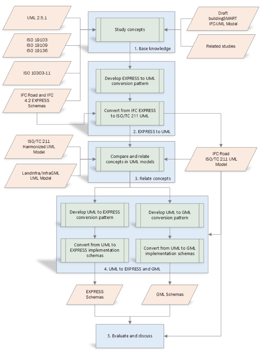
Figure 1 illustrates the materials and method used for investigating the research questions in a process with five steps. A base knowledge was established through detailed studies of the EXPRESS and UML language specifications and their use for IFC and ISO/TC 211 information models. The source materials for the studies are listed in Table 1.
Based on the knowledge from the first step, we were able to identify potential solutions and challenges for conversion, and develop a pattern for conversion from IFC concepts represented in EXPRESS to representation in UML according to ISO/TC 211 standards. The conversion pattern is described in Section 4.1, with example results in UML package and class diagrams.
The ISO/TC 211 compliant UML representation of IFC was used for comparing and relating core IFC concepts to core concepts from ISO/TC 211 standards, as described in Section 4.2. Based on the results and knowledge from the previous steps, we developed conversion patterns from UML to implementations schemas for EXPRESS and GML, which is described in Section 4.3. Finally, the results from the bidirectional conversion are evaluated and discussed in Section 5.
The data sources and tools used for the bi-directional conversions are listed in Table 2, while the complete UML models, implementation schemas and conversion scripts are available online at [49]. The notation for UML package and class diagrams as presented in Section 4 is specified in the UML specification [3] and illustrated for use in ISO/TC 211 UML models in the ISO/TC 211 Wiki on UML Best Practices [50]. Further descriptions of UML can, e.g., be found in [51].
4. Results
4.1. Conversion of IFC Models to ISO/TC 211 Compliant UML Models
4.1.1. Conversion Pattern Overview
We developed a pattern for conversion from IFC information models into a UML model according to profiles and rules defined by ISO/TC 211: The UML profile defined in ISO 19103, with extensions defined in ISO 19109 and ISO 19136; the ISO 19109 GFM; and modelling rules defined in ISO 19103, ISO 19109, and ISO 19136. The conversion pattern describes conversion from EXPRESS schemas, as the official IFC-UML is still in development. Table 3 presents an overview of the conversion pattern, while subsequent clauses describe further details of the conversion pattern.
The conversion pattern considers differences between the EXPRESS and UML languages as well as the specific use of EXPRESS for IFC and UML for standards from ISO/TC 211 and OGC. Concepts from IFC EXPRESS schemas are implemented as concepts described in the extended ISO/TC 211 UML profile and the ISO 19109 GFM.
The pattern aims to reduce the heterogeneity between BIM and GIS by moving IFC schemas into the same UML environment as GIS information models and enable the future maintenance of IFC models harmonized with standards from ISO/TC 211 and OGC. Our approach is broader than the one described in [44], where the scope of the converted ontology is conversions of existing IFC files to RDF. Our approach is also different from the work on the official IFC-UML [48], as we are relating the IFC model to core ISO/TC 211 concepts.
As our conversion pattern follows profiles and rules defined in ISO/TC 211 standards, it has some differences from the draft buildingSMART IFC-UML model [48]. The differences are listed in Table 4. Most important; the IFC-UML model has more of the EXPRESS semantics specifically defined. Contrary, our pattern converts EXPRESS primitive types to ISO 19103 types; select types to unions; and group functions and rules as operations in interfaces.
4.1.2. Schema
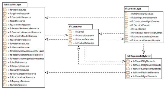
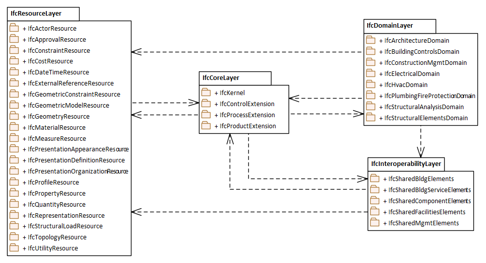
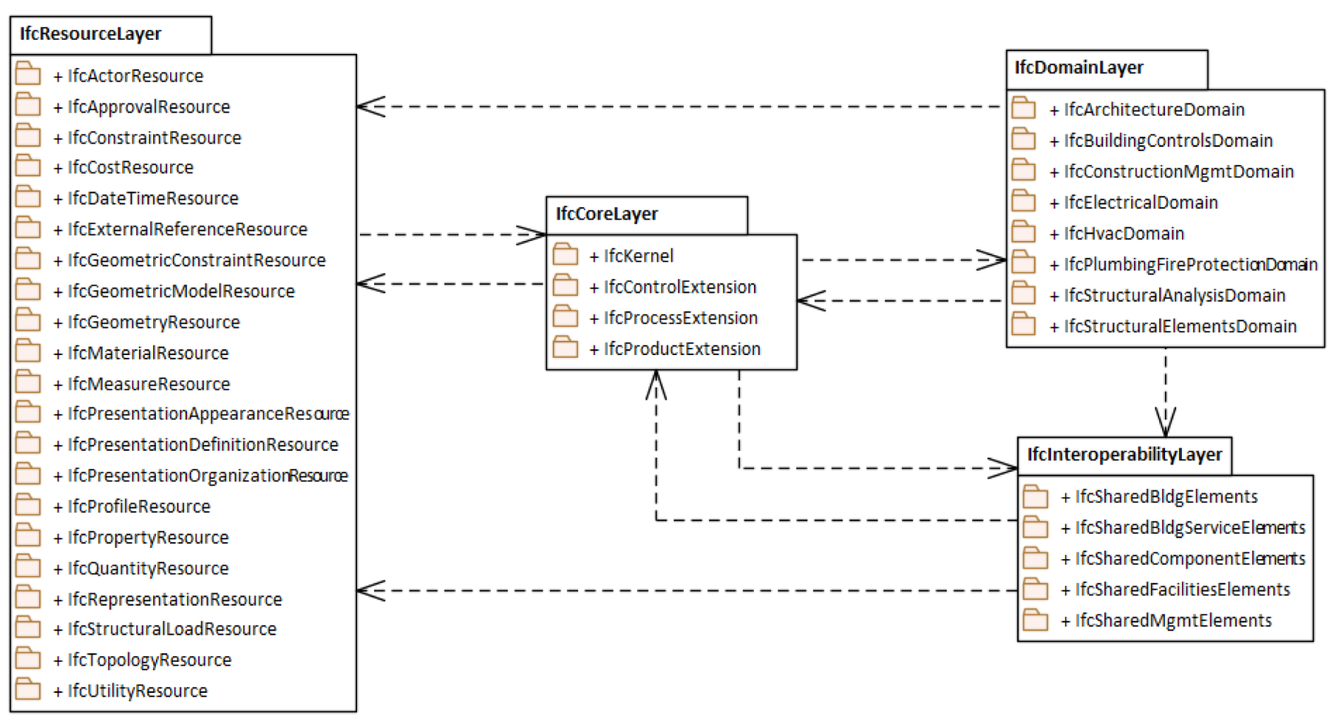
Grouping of models in smaller portions is particularly useful for large models with many elements. The core structural concept of EXPRESS is the schema, which defines the scope for a collection of items forming part or all of a model [2]. The IFC specification defines four conceptual layers with a total of 38 schemas, as presented in [29]: The Resource layer (21 schemas), the Core layer (four schemas), the Interoperability layer (five schemas) and the Domain layer (eight schemas). Despite the layer and schema architecture, the official IFC specifications are described in one large EXPRESS schema—e.g., IFC version 4.2 [29]. However, the draft IFC 4.3 Roads specification [53] that was used in the conversion was described in separate schemas according to the schema architecture in [29].
The package concept in UML is used for structuring and organizing classes and data types in UML models, equivalent to schemas in EXPRESS. Therefore, each EXPRESS schema can be converted to a UML package. The conceptual layers from IFC are maintained by grouping the packages in four main packages representing the layers, as illustrated in Figure 2. Besides, ISO 19109 defines the stereotype “ApplicationSchema” for UML packages that contain a conceptual schema for a specific domain model. According to rules in ISO 19109, an application schema shall not contain another application schema. The stereotype is therefore added only to the root IFC package in the UML model.
The Reference construct in EXPRESS specifies entities and types from other schemas that are reused in the current schema. A typical example is the reuse of elements from the IFC Resource layer schemas in Interoperability and Domain layer schemas. Our conversion pattern converts the REFERENCE FROM statements from EXPRESS to package-to-package dependencies in UML, and aggregates the dependencies further to the IFC conceptual layer packages, as illustrated in Figure 2. These package dependencies are mainly used for visualizing dependencies. The formal dependencies in the UML model are derived from elements in each package and their relations and property value domains from other packages.
4.1.3. Entity
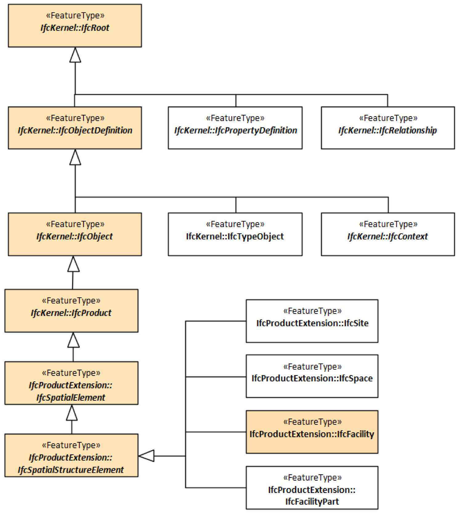
The Entity concept in EXPRESS and the Class concept in UML has been considered equivalent in several studies, for example [40,41]. The ISO 19109 GFM specializes the UML metaclass “Class” to a UML metaclass “FeatureType”, implemented with the stereotype “FeatureType”. Therefore, we convert EXPRESS entities to UML classes with stereotype “FeatureType”. Furthermore, EXPRESS, as well as UML, have concepts for abstract classes and class hierarchies. Abstract EXPRESS entities are converted to abstract UML classes, while the EXPRESS statement SUPERTYPE OF is converted to UML generalizations. Figure 3 illustrates a part of the IFC class hierarchy, emphasizing the inheritance from the core abstract superclass IfcRoot to the implementable class IfcFacility.
4.1.4. Default Datatypes and Defined Datatypes
Type declarations in EXPRESS are considered equivalent to datatypes in UML [40,41]. The EXPRESS language defines a set of default simple datatypes: BINARY, BOOLEAN, INTEGER, LOGICAL, NUMBER, REAL, and STRING. ISO 19103 defines equivalent datatypes for use in UML models of geospatial information. Our conversion pattern applies a mapping between the default EXPRESS datatypes and equivalent datatypes from ISO 19103, for use in the conversion of defined datatypes.
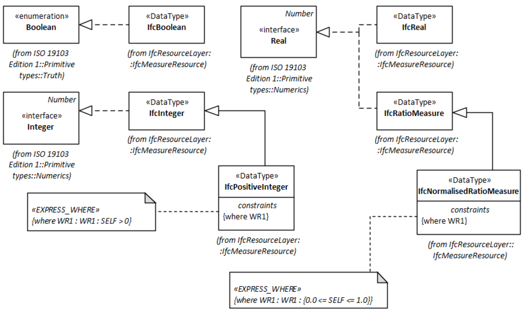
The IFC EXPRESS schemas define a range of simple core datatypes for IFC, based on the default EXPRESS datatypes. For example, IfcInteger (INTEGER), IfcReal (REAL) and IfcBoolean (BOOLEAN). Besides, more specific simple datatypes, such as IfcAreaMeasure (REAL) and IfcCountMeasure (NUMBER), are defined as well. The simple (core and specific) IFC datatypes are converted to UML datatypes with realization associations from equivalent ISO 19103 datatypes, as illustrated in Figure 4.
Constrained specializations of simple IFC datatypes, e.g., IfcPositiveInteger (IfcInteger) and IfcNormalisedRatioMeasure (IfcRatioMeasure) are converted to subtypes of the datatype they are specializing, as illustrated in Figure 4. Conversions of EXPRESS constraints on types and entities are described in Section 4.1.9.
4.1.5. Aggregation Datatypes
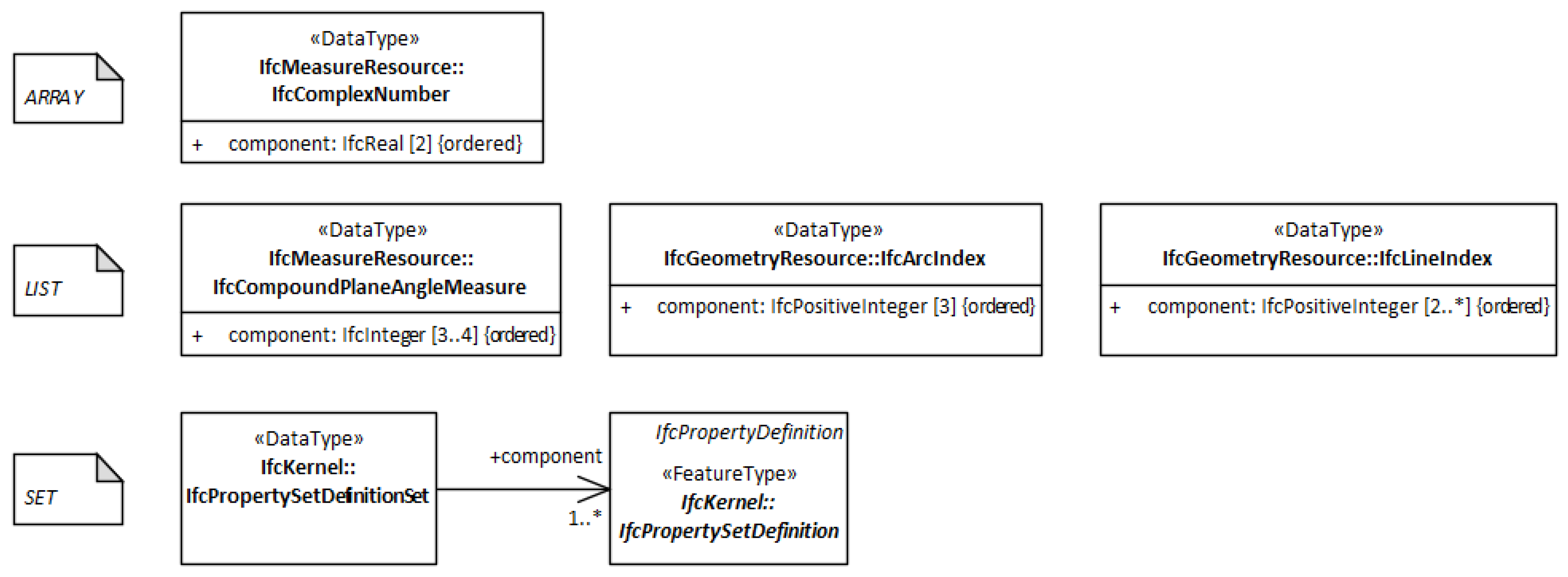
EXPRESS aggregation datatypes represent ordered or unordered collections. Three different EXPRESS aggregation datatypes are used in the IFC EXPRESS schemas: ARRAY, LIST, and SET. An array is an indexed and ordered collection with a fixed number of members; a list is an ordered collection with a flexible number of members; while a set is an unordered collection. The aggregation datatypes are extensively used for attribute domains in the IFC EXPRESS schema but only for a few type declarations: One ARRAY, three LISTs and one SET, as listed in Table 5.
Our conversion pattern for aggregation datatypes follows a similar approach as the conversion from EXPRESS to OWL described in [44]: the aggregation datatypes are converted to UML datatypes with properties (attributes or associations) that holds the collections. The multiplicity of the properties defines the number of possible instances, and multiple instances form a collection. Details of the conversion pattern are described in Table 6, while Figure 5 shows the five IFC aggregation datatypes as UML datatypes.
4.1.6. Enumerations
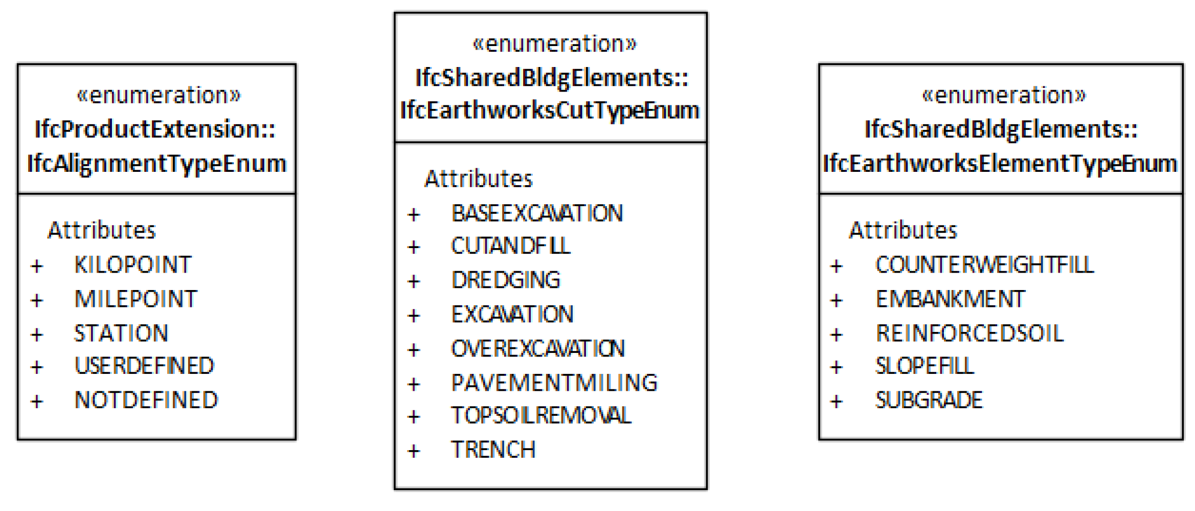
The Enumeration concept is equivalent in EXPRESS and UML and defines a set of names that are valid values for an attribute. Extensible enumerations in EXPRESS are defined with the keyword EXTENSIBLE and are equivalent to the CodeList concept defined in ISO 19103. ISO 19103 requires that the CodeList concept shall be used unless all possible values are known. However, extensible enumerations are not used in IFC. Therefore, enumerations from the IFC EXPRESS schemas are converted to UML Enumerations, as illustrated for some examples in Figure 6.
4.1.7. Select Datatypes
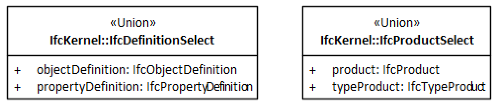
Select datatypes in EXPRESS defines a set of datatypes that may be used as the value domain for an attribute. Only one of the datatypes in the selection can be applied for an individual attribute instance. The UML Profile in ISO 19103 defines the equivalent concept Union. Therefore, IFC EXPRESS select types are converted to UML unions, as defined in ISO 19103. Figure 7 shows some examples of IFC select datatypes converted to UML unions.
4.1.8. Attributes
EXPRESS attributes are used for describing characteristics of entities, similar to UML properties (attributes and associations), which are used for describing characteristics of classes. Therefore, attributes from IFC EXPRESS schemas are converted to either UML attributes or associations. According to the accepted best practices for UML [58], properties should be modelled as attributes if the value domain is a datatype and associations if the value domain is a class. IFC EXPRESS attributes with a datatype as value domain are therefore converted to UML attributes, while IFC EXPRESS attributes with an entity as value domain are converted to associations pointing to UML FeatureTypes.
Some concerns must be taken in order to be compliant to ISO 19103 and ISO 19109 and at the same time maintain full declarations from EXPRESS. The concerns are described in the attribute conversion pattern in Table 7.
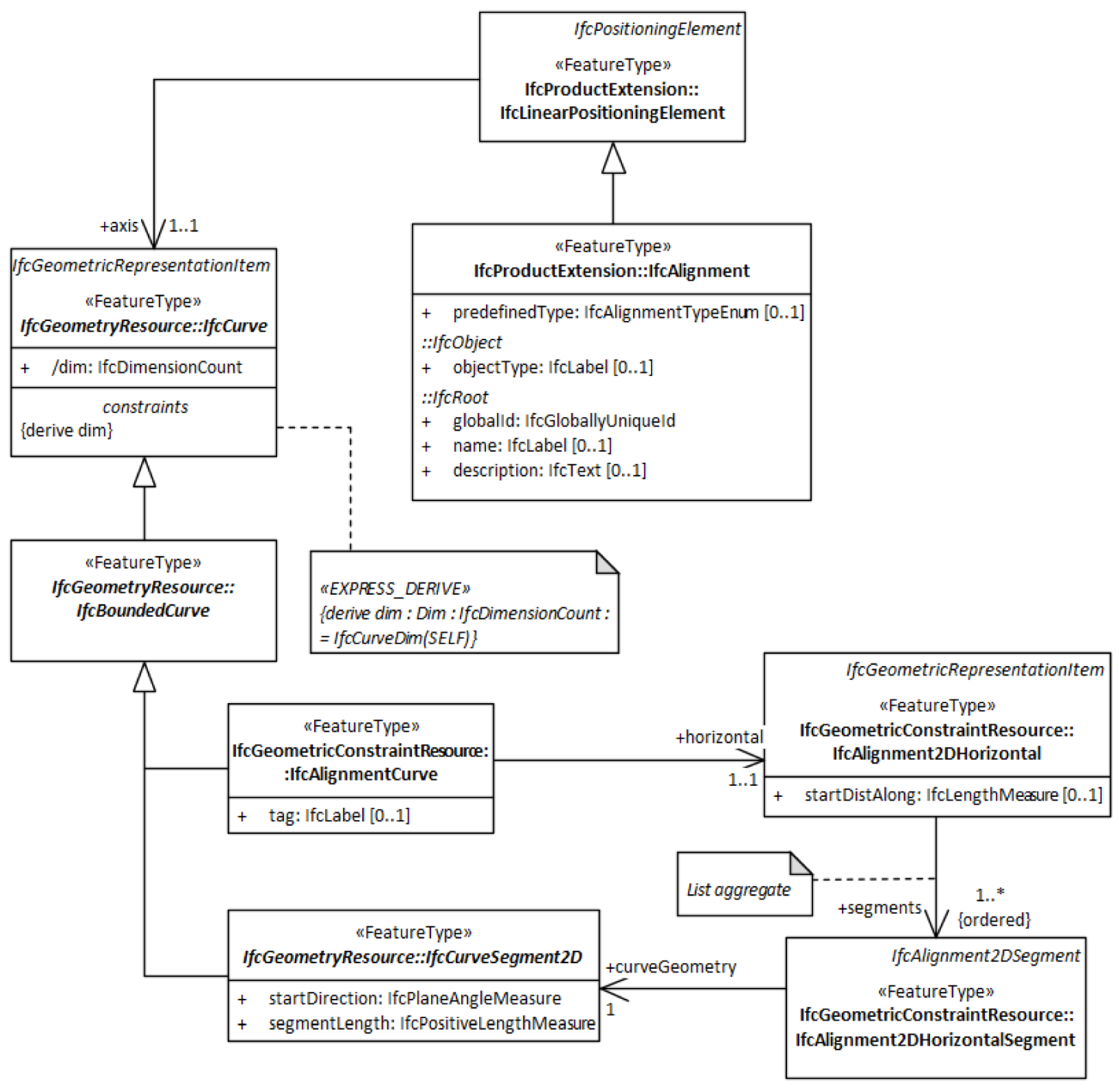
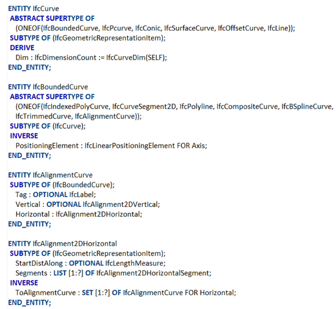
Figure 8 shows examples of IFC entities and their attributes that have been converted to UML classes and properties. The association from IfcAligment2DHorizontal to IfcAligment2DHorizontalSegment is converted from the EXPRESS attribute statement “Segments:LIST [1:?] OF IfcAlignment2DHorizontalSegment”. The attribute dim and the accompanying constraint in the class IfcCurve is converted from the EXPRESS attribute statement “DERIVE Dim:IfcDimensionCount:= IfcCurveDim(SELF)”. The class IfcAlignment shows attributes inherited from the classes IfcRoot and IfcObject.
4.1.9. Constraints
The IFC EXPRESS schemas utilize constraints to specify restrictions on types, entities and attributes, based on the EXPRESS keywords UNIQUE, INVERSE, DERIVE and WHERE, while constraints on UML elements are specified in the Object Constraint Language (OCL) [59]. The syntax from EXPRESS constraints may be translated to OCL, but the syntaxes are significantly distinct. The translation is not easy to automate and would most likely require manual work.
Furthermore, WHERE constraints on datatypes and attributes may be split into parts and stored in tagged values that can be used for deriving requirements in implementation schemas. e.g., the constraint “ValidRange:1 <= SELF <= 31” can be stored as one tagged value for the lower valid value and one for the upper valid value. The tagged values can then be implemented as “minInclusive” and “maxInclusive” restrictions in XML schemas and as a WHERE declaration in EXPRESS schemas. Similar to translations to OCL, splitting the declaration and storing parts as tagged values is a complex operation that would most likely require manual work.
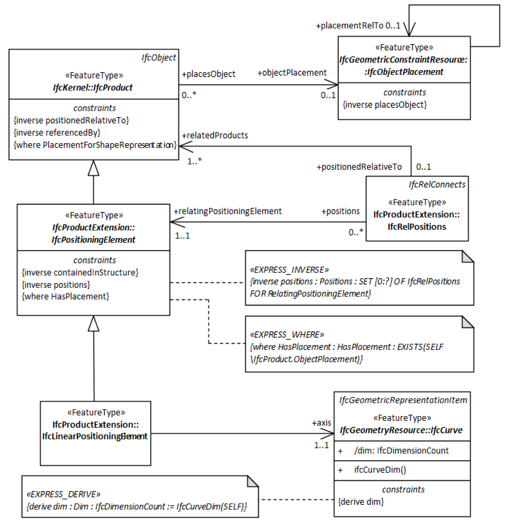
Our conversion pattern converts EXPRESS constraints to UML constraints with the EXPRESS syntax maintained, and with properties of UML constraints derived, as described in Table 8. A future extension may include conversion to OCL and splitting into tagged values. Figure 9 shows some examples of IFC constraints in the UML model.
Besides maintaining the constraints, the conversion pattern extracts the association role name and multiplicity on the side of the related entity from INVERSE declarations. The INVERSE declaration “Positions:SET [0:?] OF IfcRelPositions FOR RelatingPositioningElement” for IfcPositioningElement is extracted to the role name “positions” and multiplicity 0..* on the IfcRelPositions association end, as shown in Figure 9.
4.1.10. Functions and Rules
EXPRESS functions are used for calculating values of derived attributes and for validating the content of an IFC dataset, while EXPRESS rules are used for restricting the content of a dataset. Similar to constraints, functions and rules are written in the specific EXPRESS syntax. The equivalent concept to EXPRESS functions and rules in UML is operations.
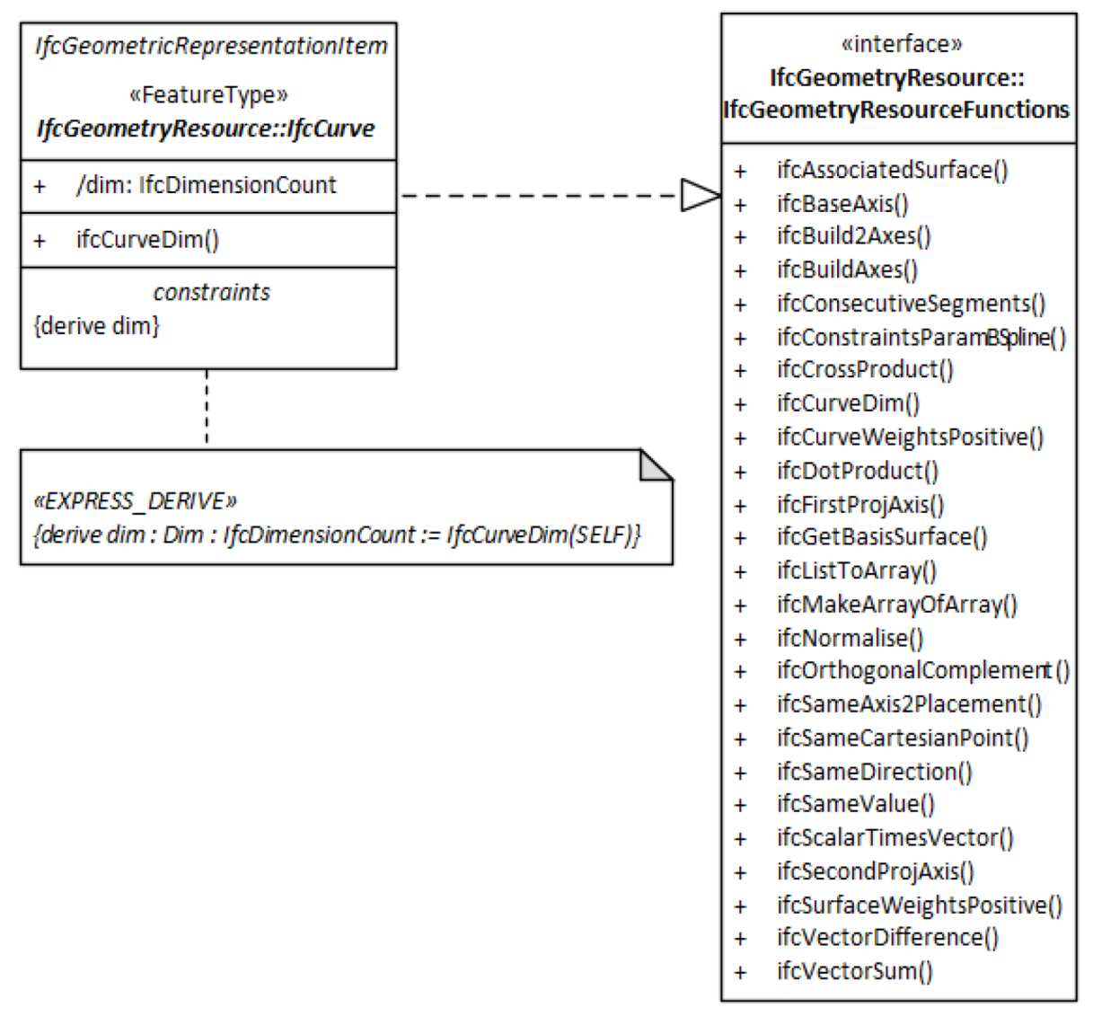
We propose to create one UML interface for EXPRESS functions and one for rules in each UML package. Every function and rule from the individual EXPRESS schema are defined as operations within these interfaces, and the original EXPRESS syntax is maintained as code. With the interface approach, relevant operations can be realized in the classes where they shall be used. For example, the class IfcCurve implements the operation ifcCurveDim in order to calculate the derived attribute “dim”, as illustrated in Figure 10.
4.2. Relating the IFC Model to Abstract Concepts from ISO/TC 211 Standards
4.2.1. Core Concepts
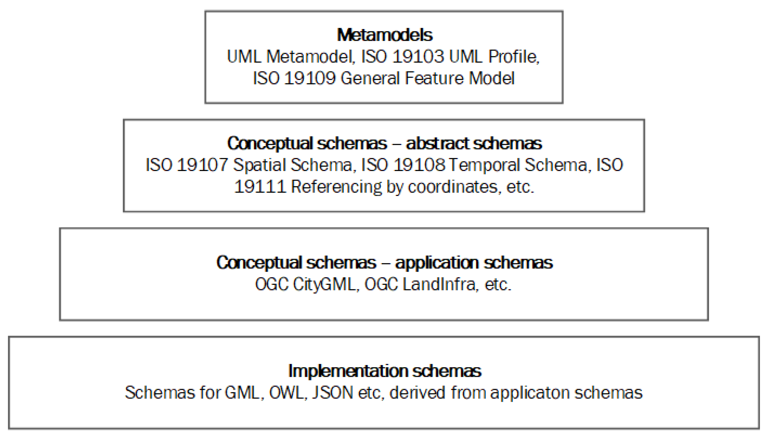
ISO 19103 defines the MDA approach for models of geospatial information with four layers of abstraction, as illustrated in Figure 11. Metamodels in the first level define how information models shall be specified; abstract schemas in the second level define basic information concepts; application schemas in level 2 reuse the abstract concepts and define specific domain models; while the fourth level contains implementation schemas for specific implementation technologies. The conceptual schemas in level two and three are independent of implementation technologies, while the implementation schemas in level four are derived from conceptual schemas based on rules for conversions.
The IFC model is a domain-specific model for the built environment, similar to OGC CityGML and LandInfra/InfraGML. The conversion pattern described in Section 4.1 converts the IFC information model to a conceptual application schema (level three in Figure 11) based on the metamodels in the top level of Figure 11—the ISO 19103 UML Profile and the ISO 19109 GFM. Besides, the IFC model contains several core concepts that may be compared and related to equivalent concepts from ISO/TC 211 abstract schemas on level 2. In particular, the schemas in the Core and Resource layers from the original IFC schema structure contain abstract concepts where equivalent concepts may be found in ISO/TC 211 schemas.
The most fundamental concepts for objects, properties and relationships in IFC are defined in the IFC Kernel schema. The concepts are similar to those defined in the ISO 19109 GFM (Figure 12), which defines concepts for feature types, attribute types, and feature associations types for use in UML models of geospatial information. However, the schemas for IFC Kernel and ISO 19109 GFM are at different levels of abstraction according to MDA: the ISO 19109 GFM is a metamodel that is implemented in UML models through stereotypes. In contrast, the IFC Kernel schema defines abstract classes with attributes that are inherited by implementable subclasses. Our conversion pattern defines all IFC EXPRESS entities as UML classes that implement the GFM metaclass FeatureType through the stereotype “FeatureType”. Entity attributes from IFC EXPRESS are defined as GFM PropertyTypes (AttributeType or FeatureAssociationRole) in UML.
Figure 13 shows some of the core classes from the IFC Kernel schema. The ultimate superclass in IFC is IfcRoot, which defines common properties that are inherited to the majority of implementable IFC classes through a hierarchy of subclasses. IfcRoot can be considered the core realization of a GFM FeatureType and its superclass IdentifiedType. The class IfcObject is the abstract superclass of implementable classes that typically represent real-world features in GIS standards. For example, the instantiable class IfcAlignment is a subclass of IfcObject and represents the same real-world feature as the InfraGML class Alignment.
The class IfcTypeObject represents a concept that is less used in GIS standards. An instance of IfcTypeObject defines characteristics that are common for several instances of IfcObject subclasses. The complete information for one specific real-world feature—e.g., a railing—may be described with two instances in an IFC data set: one instance of an IfcObject subclass (IfcRailing) with individual information such as location, and one instance of a related IfcTypeObject subclass (IfcRailingType) that contains standard information for all instances of this specific type of railing.
IfcPropertyDefinition defines the concept for flexible assignment of properties to individual objects and type objects through property sets (IfcPropertySet). While GIS standards often define fixed properties for each feature type, IFC has an extensive use of property sets that are defined outside of the IFC schemas, based on the Property Set Definition [61] structure. An equivalent concept exists in InfraGML, with the classes Property and PropertySet that can be assigned to any feature instance. The property set concept represents a flexible approach, but it is more challenging for implementation and information exchange, as the description of the content is defined outside of the schema.
Subclasses of IfcRelationship are used for relating instances of IFC classes, where the relationship class defines the type of relation: assign, associate, connect, declare, decompose or define. Unlike GFM feature associations, IFC relationships are classes that may have properties. Furthermore, the IFC schemas do not define specific relations between specific classes; only the concepts for relations between instances are defined. Similar as to property sets, this approach is more flexible but may also be more challenging for implementation and information exchange.
4.2.2. IFC Resource Schemas and ISO/TC 211 Abstract Conceptual Schemas
The relation between simple IFC EXPRESS datatypes and ISO 19103 datatypes is defined in the conversion pattern in Section 4.1, where IFC simple datatypes are automatically defined as realizations of ISO 19103 datatypes. Besides, other abstract concepts defined in IFC resource schemas and ISO/TC 211 abstract conceptual schemas can be considered equivalent as well. Improved interoperability between IFC and GIS schemas could be achieved by utilizing ISO/TC 211 datatypes—and their mapping to XML types—in IFC schemas. Therefore, we investigated relations between three IFC resource schemas and possibly equivalent ISO/TC 211 schemas: IfcDateTimeResource, IfcMeasureResource and IfcGeometryResource. Other IFC resource schemas are candidates for relations to ISO/TC 211 schemas as well and could be investigated through further studies. Table 9 lists the three selected IFC resource schemas and their ISO/TC 211 counterpart.
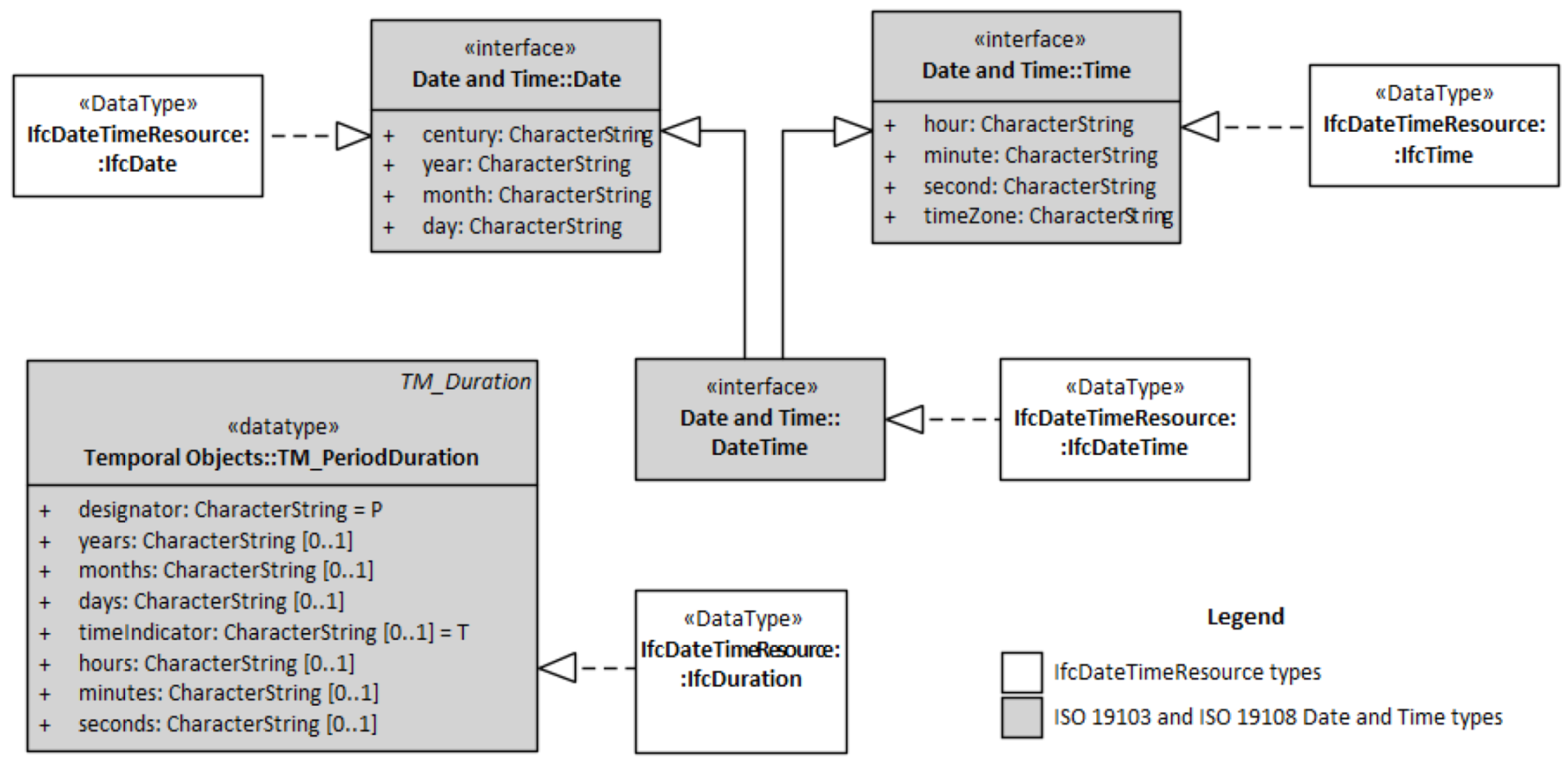
The IFC schema IfcDateTimeResource defines datatypes for time-related information. The datatypes are defined as simple datatypes in the EXPRESS schemas, supported by textual descriptions of usage and format in the IFC documentation. For example, IfcDate is defined as a string that shall be formatted as YYYY-MM-DD, while IfcTime shall be formatted as hh:mm:ss. The format requirements are only defined in the textual documentation; they are not defined in the schema. ISO 19103 and ISO 19108 defines similar concepts for date and time types, and ISO 19136 defines default mappings to standard XML schema types. The XML schema sets structure restrictions on the date and time strings. We have defined IFC date and time datatypes as realizations of equivalent ISO 19103 and ISO 19108 datatypes, as illustrated in Figure 14.
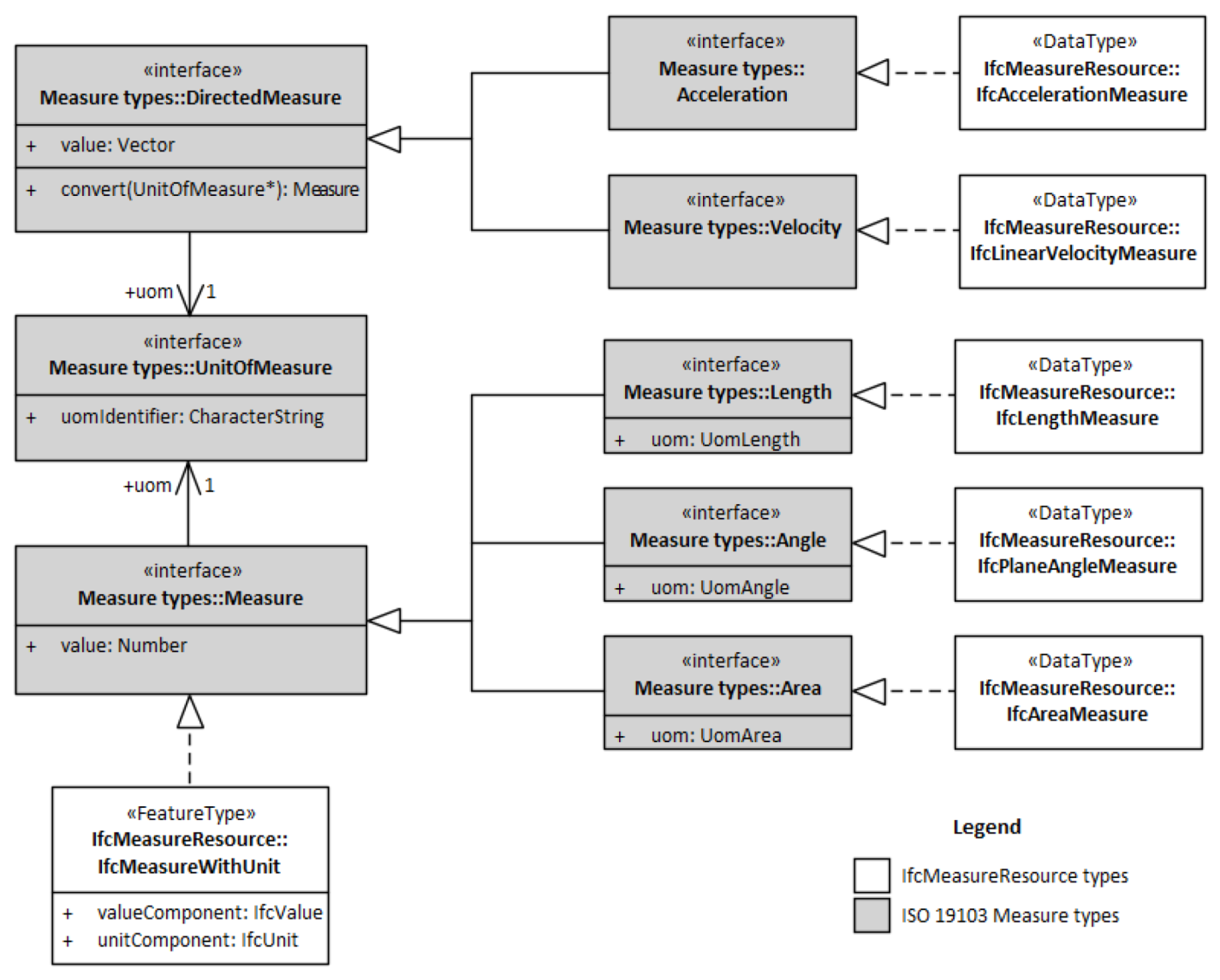
The IFC schema IfcMeasureResource defines datatypes for measure information. Similar to the IFC date and time datatypes, IFC measure datatypes are defined as simple datatypes with textual descriptions of the expected content. The unit of measure is not a part of each measured value—except for in the generic class IfcMeasureWithUnit—but default units for an IFC dataset can be specified in the attribute unitsInContext in the IfcProject class. ISO 19103 defines measure types for use in geospatial information models, where the unit of measure is given for each measured value. In order to utilize the ISO 19103 datatypes for IFC, we have defined IFC measure datatypes as realizations of equivalent ISO 19103 measure datatypes, as shown for some examples in Figure 15. Several IFC measure datatypes do not have equivalent datatypes in ISO 19103. These are defined as realizations of the core class Measure.
4.2.3. Concepts for Geometry
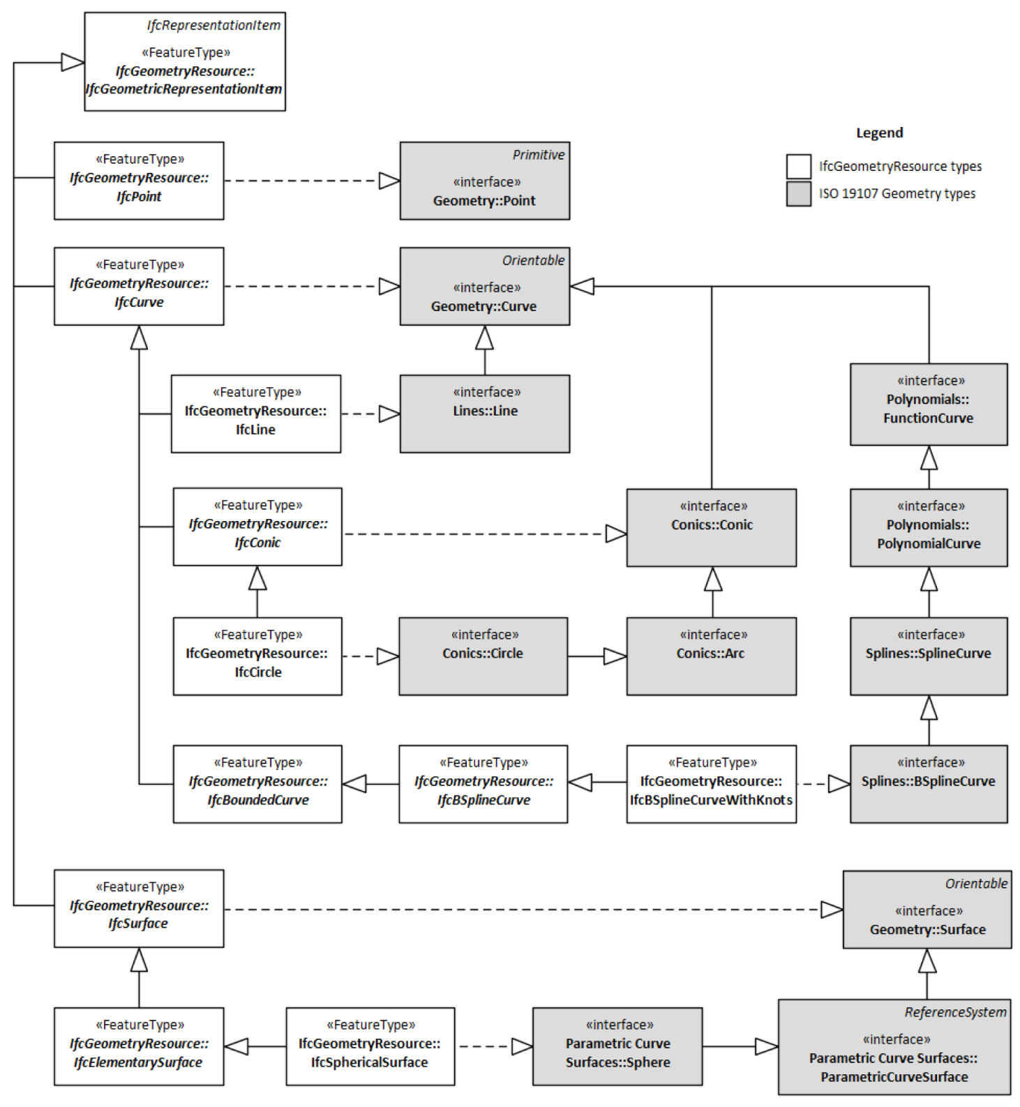
Transformation of geometry characteristics between IFC and information models based on ISO/TC 211 concepts is a complex issue that has been discussed in many studies (e.g., Donkers et al. [16]; Deng et al. [17]; Kang and Hong [32] and Ohori et al. [16,34]). The main challenge is the use of swept solids and constructive solids for the geometry of products in IFC, while GIS information models use Boundary Representation (BREP) to represent the geometry of features [17]. The geometry concepts in IFC are defined in three IFC resource schemas: The basic concepts for geometry are defined in IfcGeometryResource. More complex concepts for solid geometry representation of products are defined in IfcGeometricModelResource and IfcGeometryConstraintResource. We have limited our studies on geometry to relations between basic concepts for geometry in IfcGeometryResource and the core ISO/TC 211 geometry model in ISO 19107 [22]. We suggest that several IFC geometry types can be defined as realizations of equivalent ISO 19107 geometry types, as shown for some examples in Figure 16. However, not all IFC geometry types are defined in ISO 19107 and vice versa.
4.3. Model-Driven Derivation of Implementation Schemas
4.3.1. Conversion from UML to GML
ISO 19136 defines the GML exchange format for geospatial information; and rules for conversion from UML to XML implementation schemas for GML. The open-source software ShapeChange [56] has implemented the rules from ISO 19136 as well as additional rules for the automated derivation of GML implementation schemas. Our converted UML model of IFC was designed according to ISO 19109, and GML implementation schemas could then be derived directly with ShapeChange. We used the same modularized structure for the GML schemas as for the UML model, with one main application schema and individual GML schema files for each UML package.
The realization associations described in Section 4.1 and Section 4.2 were used for automated schema mappings between IFC and ISO/TC 211 datatypes, in order to improve interoperability with GIS applications and databases. IFC classes (feature types and datatypes) were analyzed for possible mapping to ISO/TC 211 datatypes if they were (1) referenced as the value domain of a property, and (2) were connected to an ISO/TC 211 datatype through a realization. Two approaches for schema mapping were applied, depending on the complexity of the referenced class and its hierarchy of specializations: Replacement with an ISO/TC 211 datatype; or modification of the IFC class.
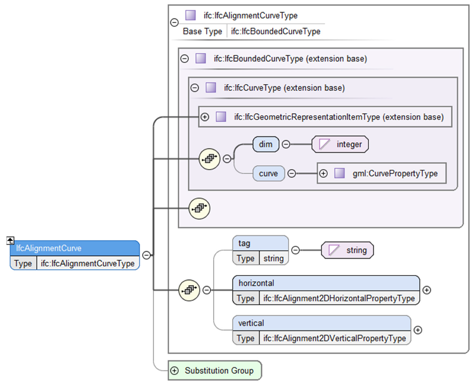
For simplicity, we made a presumption for the analyzed classes: specializations of an analyzed class describe equivalent concepts as the connected ISO/TC 211 datatype if the subtype hierarchy is entirely within the same package as the class itself or do not have any own properties. For example, specializations of a measure type within IfcMeasureResource all describe equivalent concepts to specializations of the related ISO 19103 measure datatype. Based on the presumption, the value domains of 797 of 827 analyzed properties could be replaced with ISO/TC 211 datatypes. The remaining 30 properties all referenced the classes IfcSurface or IfcCurve. IfcSurface has the complex specialization IfcSectionedSurface in the IfcGeometricModelResource package, while IfcCurve has the complex specialization IfcAlignmentCurve in the IfcGeometricConstraintResource package. We considered that the complex specializations needed to be maintained, and the two classes IfcCurve and IfcSurface could therefore not be replaced with the ISO 19107 datatypes Curve and Surface. The link to ISO 19107 for these property types was instead established by adding geometry attributes with datatype Curve for IfcCurve and Surface for IfcSurface.
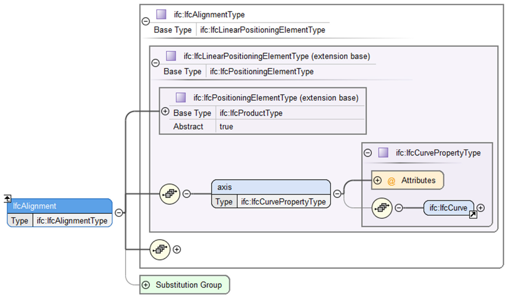
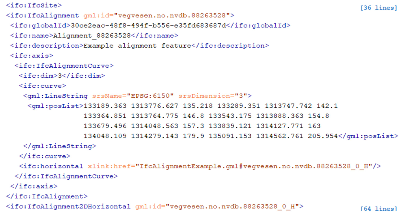
Figure 17 and Figure 18 show XML schema views of the classes IfcAligment and IfcAlignmentCurve from the derived GML implementation schemas. IfcAlignment is a subtype of IfcLinearPositioningElement and inherits the “axis” association to IfcCurve. IfcAlignmentCurve is a subtype of IfcCurve, which was connected to the ISO 19107 datatype “Curve”. The new attribute “curve” enables IfcCurve and subtypes to have curve geometries according to ISO 19107, while at the same time, the complexity of the classes and the hierarchy is maintained. The property type for the attribute “dim” in IfcCurve is mapped from “IfcDimensionCount” to the XML type “integer”, while the property type for the attribute “tag” in IfcAlignmentCurve is mapped from “IfcLabel” to the XML type “string”. Figure 19 shows a fragment of an example GML instance of IfcAlignment and IfcAlignmentCurve.
4.3.2. Conversion from UML to IFC EXPRESS
While rules for conversion from UML to GML are defined in ISO 19136, no such rules are yet defined for conversion to EXPRESS implementation schemas. We suggest a set of conversion rules that reverse the EXPRESS to UML conversion described in Table 3, Table 6, Table 7 and Table 8. Table 10 summarizes our suggested rules for conversion from UML to EXPRESS.
In order to automate the conversion, we developed a script in Enterprise Architect, where we implemented the conversion rules from Table 10. As for the GML implementation schemas, we used the same modularized structure as in the UML model, with one EXPRESS schema file for each UML package. Figure 20 shows a selection of declarations from the exported EXPRESS schema files, representing the same UML classes as the extracts from GML schemas in Figure 17 and Figure 18.
5. Evaluation and Discussion
Literature studies have shown that there has been an increasing interest and amount of research on the integration of BIM and GIS over the last years. Information exchange and conversion of semantics have been identified as a significant challenge for such integration. Still, most studies have investigated the integration of application schemas and data instances and not integration at the abstract conceptual level where the core semantics are defined. We aimed to improve the integration of core concepts from information models for BIM and GIS—independent of application schema—by moving the core concepts into a shared environment. The approach for reaching this goal was to describe concepts from both application domains in UML according to modelling rules from ISO/TC 211.
Our first research question asked for potential solutions and challenges for the conversion of the IFC information model to a UML model according to GIS standards. We developed a pattern that covers core conversion as well as the more specific use of EXPRESS for IFC and UML for GIS information models, and applied the pattern for conversion of the draft IFC Road EXPRESS schemas. The conversion pattern (described in Section 4.1) and the results from the conversion show that most EXPRESS concepts used for IFC have equivalent concepts in UML according to ISO/TC 211 standards and profiles and can be converted through simple conversions. However, we identified challenges with some concepts that need a more complex and controlled conversion—specifically aggregation datatypes (Table 6) and aggregation properties (Table 7); constraints (Table 8); and functions and rules.
We defined a UML representation of EXPRESS aggregation data types that maintained the collections, but that may need further improvement for complex aggregations of other aggregations. For constraints, functions and rules, the distinct syntax for different implementation technologies is a challenge. We considered a translation from EXPRESS syntax to OCL and tagged values, for implementation in other technologies than EXPRESS. All codes would then need to be maintained in the distinct syntaxes, or complex conversion rules from OCL to EXPRESS must be developed. Whether or not such translation is needed will depend on the use of the implementation technologies. We believe a translation is relevant in order to enable the use of GML implementation schemas for controlling data according to constraints, functions and rules.
Our second research question asked for relationships that could be defined between concepts in the IFC information model and core ISO/TC 211 standards. The results in Section 4.2 show that the ISO/TC 211 compliant UML representation of the IFC model was useful for comparing and linking concepts defined in different application domains. Core IFC classes in the IFC Kernel schema can be considered core realizations of ISO 19109 GFM metaclasses. Furthermore, basic IFC datatypes for date, time, and measures can be linked to equivalent datatypes from ISO/TC 211 standards. Therefore, a shared understanding of these datatypes may be achieved. However, we will question whether it is optimal that any of the two application domains shall define these and other universal datatypes. Instead, referring to datatypes independent of application domain—defined in core external vocabularies—would improve interoperability between the two application domains as well as with other domains.
Unlike datatypes for date, time and measures, datatypes and concepts for geometry are more naturally owned by one of the two application domains in question. We defined links between several core geometry concepts in the IFC model and ISO/TC 211 models, but we also observed that not all geometry types could be linked one-to-one. Further harmonization of geometry types between the two application domains would give significant improvement of interoperability. Basic geometry types should only be defined in one of the application domains, and then used in both, as well as in any other application domain concerning geospatial information.
The third research question asked for potential solutions and challenges for deriving implementation schemas for EXPRESS and GML from UML models of IFC. The results in Section 4.3 show that conversions were possible to both GML and EXPRESS directly from the UML model, supported by some implementation-specific semantics in tagged values. We applied a mapping to ISO/TC 211 datatypes for the GML conversion, in order to achieve better interoperability with GIS applications and databases. The mapping of geometry datatypes was essential for enabling interoperability that included geometry characteristics and was also the most challenging part, due to the distinct geometry models in IFC and ISO 19107. The conversion would be less complicated if the two application domains were using a shared model of geometry datatypes.
The IFC-UML model developed by buildingSMART is expected to replace EXPRESS schemas as the original conceptual IFC model in the future. The comparison in Table 4 shows that there are some minor differences between the draft IFC-UML model and our ISO/TC 211 compliant UML model. If the final IFC-UML model has the same structure as the draft, our conversion pattern must be adapted for conversions from the IFC-UML model to an ISO/TC 211 compliant UML model. However, we consider that a better solution would be to model the original IFC-UML model according to ISO/TC 211 profiles and rules. Our bi-directional conversion has shown that all semantics from the IFC model could be maintained in an ISO/TC 211 compliant model and that implementation schemas could be derived from the model.
6. Conclusions and Further Work
This study has investigated whether harmonized core UML concepts for information models in BIM and GIS can be a way forward for improved interoperability between the two application domains. We developed a conversion pattern from IFC EXPRESS schemas from the BIM application domain to UML models according to ISO/TC 211 standards from the GIS application domain. The model was further refined with links between core concepts from IFC and ISO/TC 211 models and tested for conversions to implementation schemas in the GML and EXPRESS formats.
The research showed that all semantics from the IFC model could be converted to an ISO/TC 211 compliant UML model and that implementation schemas for both application domains could be derived from the UML model. Some implementation-specific semantics for GML and EXPRESS need to be maintained as tagged values. Enhanced technology-independent implementation can be achieved by translating constraints, rules and functions specified in the EXPRESS syntax to OCL and tagged values for implementation in GML schemas. Most important; the representation of information models from both application domains in a shared environment was useful for understanding, linking, mapping and reusing concepts between IFC and core GIS standards.
Improved interoperability at application schema and data instance level may be achieved by using shared core concepts as a fundament for application schemas in both domains. Exchange of information for use in planning, constructing, using, and maintaining the built environment would be a less complicated issue with a shared understanding of the semantics for digital representation of real-world phenomena. We consider such common understanding more important than the choice of modelling language.
Further work following this study should include an improved linking and harmonization of core concepts. Domain-specific concepts should be replaced with shared concepts, and externally defined vocabularies should be reused in both application domains when possible. A shared model for geometry types is particularly important for improved interoperability.
Author Contributions
Conceptualization, Knut Jetlund; methodology, Knut Jetlund, Erling Onstein and Lizhen Huang; validation, Knut Jetlund; formal analysis, Knut Jetlund; investigation, Knut Jetlund; data curation, Knut Jetlund; writing—original draft preparation, Knut Jetlund; writing—review and editing, Erling Onstein and Lizhen Huang; visualization, Knut Jetlund; supervision, Erling Onstein and Lizhen Huang. All authors have read and agreed to the published version of the manuscript.
Funding
This research was funded by The Norwegian Public Roads Administration and The Research Council of Norway. NTNU Open Access publishing funds cover the article processing charges.
Conflicts of Interest
The authors declare no conflict of interest.
References
- buildingSmart International. IFC Specifications Database. 2019. Available online: https://technical.buildingsmart.org/standards/ifc/ifc-schema-specifications/ (accessed on 10 January 2020).
- ISO. Industrial Automation Systems and Integration—Product Data Representation and Exchange—Part 11: Description Methods: The EXPRESS Language Reference Manual; ISO/TC 184 SC 4, ISO 10303-11:2004; ISO: Geneva, Switzerland, 2004. [Google Scholar]
- Object Management Group. Unified Modelling Language Specification Version 2.5.1; Object Management Group: Needham, MA, USA, 2017. [Google Scholar]
- ISO. Information technology—Object Management Group Unified Modeling Language (OMG UML)—Part 2: Superstructure; ISO/IEC JTC 1/SC 7, ISO/IEC 19505-2:2012; ISO: Geneva, Switzerland, 2012. [Google Scholar]
- ISO. Information technology—Object Management Group Unified Modeling Language (OMG UML)—Part 1: Infrastructure; ISO/IEC JTC 1/SC 7, ISO/IEC 19505-1:2012; ISO: Geneva, Switzerland, 2012. [Google Scholar]
- Object Management Group. Model Driven Architecture (MDA) Guide Rev. 2.0; Object Management Group: Needham, MA, USA, 2014. [Google Scholar]
- Coetzee, S.; Plews, R.; Brodeur, J.; Hjelmager, J.; Jones, A.; Jetlund, K.; Grillmayer, R.; Wasström, C. Standards—Making Geographic Information Discoverable, Accessible and Usable for Modern Cartography. In Service-Oriented Mapping: Changing Paradigm in Map Production and Geoinformation Management; Döllner, J., Jobst, M., Schmitz, P., Eds.; Springer International Publishing: Cham, Switzerland, 2019; pp. 325–344. [Google Scholar]
- Liu, X.; Wang, X.; Wright, G.; Cheng, J.C.; Li, X.; Liu, R. A State-of-the-Art Review on the Integration of Building Information Modeling (BIM) and Geographic Information System (GIS). ISPRS Int. J. Geo-Inf. 2017, 6, 53. [Google Scholar] [CrossRef] [Green Version]
- Zhu, J.; Wright, G.; Wang, J.; Wang, X. A Critical Review of the Integration of Geographic Information System and Building Information Modelling at the Data Level. ISPRS Int. J. Geo-Inf. 2018, 7, 66. [Google Scholar] [CrossRef] [Green Version]
- Song, Y.; Wang, X.; Tan, Y.; Wu, P.; Sutrisna, M.; Cheng, J.; Hampson, K. Trends and Opportunities of BIM-GIS Integration in the Architecture, Engineering and Construction Industry: A Review from a Spatio-Temporal Statistical Perspective. ISPRS Int. J. Geo-Inf. 2017, 6, 397. [Google Scholar] [CrossRef] [Green Version]
- Kumar, K.; Labetski, A.; Ohori, K.A.; Ledoux, H.; Stoter, J. The LandInfra standard and its role in solving the BIM-GIS quagmire. Open Geospat. Data Softw. Stand. 2019, 4. [Google Scholar] [CrossRef] [Green Version]
- Onstein, E.; Tognoni, M.G. “Building permits” as proof of concepts in merging GIS and BIM information: A case study. WIT Trans. Built Environ. 2017, 169, 155–166. [Google Scholar]
- Roxin, A.; Hbeich, E. Semantic interoperability between BIM and GIS–review of existing standards and depiction of a novel approach. In Proceedings of the 36th CIB W78–Information Technology for Construction, Northumbria, UK, 18–20 September 2019. [Google Scholar]
- Gilbert, T.; Rönsdorf, C.; Plume, J.; Simmons, S.; Nisbet, N.; Gruler, H.-C.; Kolbe, T.; van Berlo, L.; Mercer, A. Built Environment Data Standards and Their Integration: An Analysis of IFC, CityGML and LandInfra; Open Geospatial Consortium: Wayland, MA, USA; buildingSMART International: London, UK, 2020. [Google Scholar]
- Open Geospatial Consortium. OGC CityGML. 2019. Available online: https://www.opengeospatial.org/standards/citygml (accessed on 18 February 2020).
- Donkers, S.; Ledoux, H.; Zhao, J.; Stoter, J. Automatic conversion of IFC datasets to geometrically and semantically correct CityGML LOD3 buildings. Trans. GIS 2016, 20. [Google Scholar] [CrossRef] [Green Version]
- Deng, Y.; Cheng, J.C.; Anumba, C. Mapping between BIM and 3D GIS in different levels of detail using schema mediation and instance comparison. Autom. Constr. 2016, 67, 1–21. [Google Scholar] [CrossRef]
- ISO. Industry Foundation Classes (IFC) for Data Sharing in the Construction and Facility Management industries—Part 1: Data Schema; ISO/TC 59/SC 13, ISO 16739-1:2018; ISO: Geneva, Switzerland, 2018. [Google Scholar]
- ISO. Geographic Information—Conceptual Schema Language; ISO/TC 211, ISO 19103:2015; ISO: Geneva, Switzerland, 2015. [Google Scholar]
- ISO. Geographic information—Rules for Application Schema; ISO/TC 211, ISO 19109:2015; ISO: Geneva, Switzerland, 2015. [Google Scholar]
- ISO. Geographic information—Geography Markup Language (GML); ISO/TC 211, ISO 19136:2007; ISO: Geneva, Switzerland, 2007. [Google Scholar]
- ISO. Geographic Information—Spatial Schema; ISO/TC 211, ISO 19107:2019; ISO: Geneva, Switzerland, 2019. [Google Scholar]
- ISO. Geographic Information—Referencing by Coordinates; ISO/TC 211, ISO 19111:2019; ISO: Geneva, Switzerland, 2019. [Google Scholar]
- INSPIRE. INSPIRE Data Specifications. 2020. Available online: https://inspire.ec.europa.eu/data-specifications/2892 (accessed on 31 March 2020).
- CEN/TC 278. Intelligent Transport Systems—ITS Spatial Data—Data Exchange on Changes in Road Attributes; CEN/TS 17268:2018 I; CEN: Brussels, Belgium, 2018. [Google Scholar]
- Open Geospatial Consortium. OGC LandInfra/InfraGML. 2017. Available online: https://www.opengeospatial.org/standards/infragml (accessed on 18 February 2020).
- Open Geospatial Consortium. OGC® Land and Infrastructure Conceptual Model Standard (LandInfra); Open Geospatial Consortium: Wayland, MA, USA, 2016. [Google Scholar]
- buildingSmart International. Infrastructure Room. 2019. Available online: https://www.buildingsmart.org/standards/rooms/infrastructure (accessed on 30 October 2019).
- buildingSmart International. Industry Foundation Classes Version 4.2 bSI Draft Standard. 2019. Available online: https://standards.buildingsmart.org/IFC/DEV/IFC4_2/FINAL/HTML/ (accessed on 10 January 2020).
- Open Geospatial Consortium. OGC InfraGML 1.0—Part 3—Alignments—Encoding Standard; Open Geospatial Consortium: Wayland, MA, USA, 2017. [Google Scholar]
- Hor, A.-H.; Jadidi, A.; Sohn, G. BIM-GIS INTEGRATED GEOSPATIAL INFORMATION MODEL USING SEMANTIC WEB AND RDF GRAPHS. ISPRS Ann. Photogramm. Remote Sens. Spat. Inf. Sci. 2016, 3, 73–79. [Google Scholar] [CrossRef]
- Kang, T.W.; Hong, C.H. IFC-CityGML LOD mapping automation using multiprocessing-based screen-buffer scanning including mapping rule. KSCE J. Civil Eng. 2018, 22, 373–383. [Google Scholar] [CrossRef]
- Knoth, L.; Scholz, J.; Strobl, J.; Mittlböck, M.; Vockner, B.; Atzl, C.; Rajabifard, A.; Atazadeh, B. Cross-Domain Building Models—A Step towards Interoperability. ISPRS Int. J. Geo-Inf. 2018, 7, 363. [Google Scholar] [CrossRef] [Green Version]
- Arroyo Ohori, G.A.K.; Diakite, A.A.; Krijnen, T.; Ledoux, H.; Stoter, J.E. Processing BIM and GIS Models in Practice. ISPRS Int. J. Geo-Inf. 2018, 7, 311. [Google Scholar] [CrossRef] [Green Version]
- Vilgertshofer, S.; Amann, J.; Willenborg, B.; Borrmann, A.; Kolbe, T. Linking BIM and GIS Models in Infrastructure by Example of IFC and CityGML. Comput. Civil Eng. 2017, 2017, 133–140. [Google Scholar]
- Niestroj, M.G.; McMeekin, D.A.; Helmholz, P. Overview of standards towards road asset information exchange. Int. Arch. Photogramm. Remote Sens. Spat. Inf. Sci. 2018, XLII-4, 443–450. [Google Scholar] [CrossRef] [Green Version]
- ISO. GIS (Geospatial)/BIM Interoperability; ISO/TC 59/SC 13, ISO/WD TR 23262; ISO: Geneva, Switzerland, 2019. [Google Scholar]
- INTERLINK Project. EUROTL Framework Overview. 2018. Available online: https://www.roadotl.eu/static/eurotl-ontologies/index.html (accessed on 10 January 2020).
- Luiten, B.; Böhms, M.; O’Keeffe, A.; van Nederveen, S.; Bakker, J.; Wikström, L. A hybrid linked data approach to support asset management. In Life-Cycle of Engineering Systems: Emphasis on Sustainable Civil Infrastructure, Proceedings of the Fifth International Symposium on Life-Cycle Civil Engineering (IALCCE 2016) Delft, The Netherlands, 16–19 October 2016; CRC Press: Boca Raton, FL, USA; Taylor & Francis Group: London, UK, 2016. [Google Scholar]
- Arnold, F.; Podehl, G. Best of Both Worlds—A Mapping from EXPRESS-G to UML; Springer: Berlin/Heidelberg, Germany, 1999. [Google Scholar]
- Krause, F.L.; Kaufmann, U. Meta-Modelling for Interoperability in Product Design. CIRP Ann. 2007, 56, 159–162. [Google Scholar] [CrossRef]
- Exff Project. 2003. Available online: http://exff.sourceforge.net/docs/e2u_mapping.html (accessed on 15 January 2020).
- Object Management Group. Reference Metamodel for the EXPRESS Information Modeling Language; Object Management Group: Needham, MA, USA, 2015. [Google Scholar]
- Pauwels, P.; Terkaj, W. EXPRESS to OWL for construction industry: Towards a recommendable and usable ifcOWL ontology. Autom. Constr. 2016, 63, 100–133. [Google Scholar] [CrossRef]
- Terkaj, W.; Pauwels, P. A Method to generate a Modular ifcOWL Ontology. In Proceedings of the 8th International Workshop on Formal Ontologies Meet Industry, Bolzano, Italy, 21–23 September 2017. [Google Scholar]
- McGlinn, K.; Wagner, A.; Pauwels, P.; Bonsma, P.; Kelly, P.; O’sullivan, D. Interlinking geospatial and building geometry with existing and developing standards on the web. Autom. Constr. 2019, 103, 235–250. [Google Scholar] [CrossRef]
- Van Berlo, L. Future Technology Presentation buildingsmart Summit Beijing; Linkedin: Sunnyvale, CA, USA, 2019. [Google Scholar]
- buildingSmart International. NextGen-IFC. 2019. Available online: https://github.com/buildingSMART/NextGen-IFC (accessed on 24 January 2020).
- Jetlund, K. IFC2GML. 2020. Available online: https://github.com/jetgeo/IFC2GML (accessed on 23 April 2020).
- ISO/TC 211. Introduction to UML. 2018. Available online: https://github.com/ISO-TC211/UML-Best-Practices/wiki/Introduction-to-UML (accessed on 20 March 2020).
- Miles, R.R.; Hamilton, K. Learning UML 2.0, 1st ed.; O’Reilly: Sebastopol, CA, USA, 2006. [Google Scholar]
- Schenck, D.; Wilson, P. Information Modelling: The EXPRESS Way; Oxford University Press: New York, NY, USA, 1994. [Google Scholar]
- buildingSMART International. IFC4x3—FIRST_DRAFT 2019. Unpublished.
- ISO/TC 211. Harmonized Model Maintenance Group, The ISO/TC 211 Harmonized Model. 2019. Available online: http://iso.sparxcloud.com (accessed on 30 October 2019).
- Sparx Systems Pty Ltd. Enterprise Architect Version 15. 2020. Available online: https://sparxsystems.com/products/ea/index.html (accessed on 10 January 2020).
- Interactive instruments GmbH. ShapeChange. Available online: http://shapechange.net (accessed on 15 January 2020).
- Syncro Soft SRL. Oxygen XML Editor 22. 2020. Available online: https://www.oxygenxml.com/xml_editor.html (accessed on 20 March 2020).
- Bellekens, G. UML Best Practice: Attribute or Association. 2011. Available online: https://bellekens.com/2011/08/10/uml-best-practice-attribute-or-association/ (accessed on 10 January 2020).
- Object Management Group. The Object Constraint Language Version 2.4; Object Management Group: Needham, MA, USA, 2014. [Google Scholar]
- Jetlund, K.; Onstein, E.; Huang, L. Information Exchange between GIS and Geospatial ITS Databases Based on a Generic Model. ISPRS Int. J. Geo-Inf. 2019, 8, 141. [Google Scholar] [CrossRef] [Green Version]
- buildingSmart International. PSD: Property Set Definition XSD. 2013. Available online: http://standards.buildingsmart.org/IFC/RELEASE/IFC4/FINAL/PSD/PSD_IFC4.xsd (accessed on 10 January 2020).
Figure 1.
The research process and materials for the study.

Figure 2.
UML package diagram showing the core structure of the IFC-UML Model.

Figure 3.
UML class diagram showing a part of the IFC class hierarchy from IfcRoot to IfcFacility.

Figure 4.
UML class diagram showing examples of IFC simple datatypes as realizations of ISO 19103 datatypes.
Figure 4.
UML class diagram showing examples of IFC simple datatypes as realizations of ISO 19103 datatypes.

Figure 5.
UML class diagram showing IFC aggregation datatypes in UML.

Figure 6.
UML class diagram showing examples of IFC enumerations.

Figure 7.
UML class diagram showing examples of IFC select datatypes converted to UML unions.

Figure 8.
UML class diagram showing examples of IFC attributes converted to UML.

Figure 9.
UML class diagram showing examples of IFC constraints converted to UML.

Figure 10.
UML class diagram showing realization of the operation IfcCurveDim in the class IfcCurve.
Figure 10.
UML class diagram showing realization of the operation IfcCurveDim in the class IfcCurve.

Figure 11.
ISO 19103 MDA Levels of abstraction. Adapted from [60].
Figure 11.
ISO 19103 MDA Levels of abstraction. Adapted from [60].

Figure 12.
UML class diagram showing the ISO 19109 General Feature Model (GFM).

Figure 13.
UML class diagram showing the IFC Kernel core classes.

Figure 14.
UML class diagram showing IFC Date and time types as realizations of ISO 19103 and ISO 19108 datatypes.
Figure 14.
UML class diagram showing IFC Date and time types as realizations of ISO 19103 and ISO 19108 datatypes.

Figure 15.
UML class diagram showing examples of IFC measure types as realizations of ISO 19103 measure types.
Figure 15.
UML class diagram showing examples of IFC measure types as realizations of ISO 19103 measure types.

Figure 16.
UML class diagram showing examples of IFC geometry types as realizations of ISO 19107 geometry types.
Figure 16.
UML class diagram showing examples of IFC geometry types as realizations of ISO 19107 geometry types.

Figure 17.
Extract from the IfcProductExtension GML schema, illustrated in Oxygen XML Editor [57].
Figure 17.
Extract from the IfcProductExtension GML schema, illustrated in Oxygen XML Editor [57].

Figure 18.
Extract from the IfcGeometricConstraintResource GML schema, illustrated in Oxygen XML Editor [57].
Figure 18.
Extract from the IfcGeometricConstraintResource GML schema, illustrated in Oxygen XML Editor [57].

Figure 19.
Extract of an example GML file for IFC.

Figure 20.
Selected declarations from the derived EXPRESS schema files.


Table 1.
Sources for comparisons of IFC EXPRESS and ISO/TC 211 UML.
| Language | Source |
|---|---|
| EXPRESS | ISO 10303-11: The EXPRESS language reference manual [2] |
| Information modelling: The EXPRESS way (Schenk and Wilson) [52] | |
| EXPRESS for IFC | IFC 4.3 (IFC Road) first draft EXPRESS schemas [53] |
| IFC 4.2 candidate standard EXPRESS schemas [29] | |
| UML | The UML Specification version 2.5.1 [3] |
| UML for IFC | The draft IFC-UML model from buildingSMART [48] |
| UML for geospatial information | ISO 19103 [19]: Conceptual schema language |
| ISO 19109 [20]: Rules for application schema | |
| ISO 19136 [21]: Geography Markup Language (GML) | |
| UML models for ISO/TC 211 standards [54] | |
| UML models from OGC: Land and Infrastructure Conceptual Model (LandInfra) version 1.0, and InfraGML Encoding Standards version 1.0 |
Table 2.
Data sources and tools.
| Source or Tool | Description |
|---|---|
| IFC Road EXPRESS schemas [53] | Converted to UML through the conversion pattern. |
| UML models for ISO/TC 211 standards [54] | Imported from the ISO/TC 211 Harmonized UML Model. |
| Enterprise Architect version 15 [55] | The application used for UML modelling and scripting of the bi-directional conversion between UML and EXPRESS. |
| ShapeChange version 2.8 [56] | The application used for conversion from UML to GML. |
| Oxygen XML Editor version 22 [57] | The application used for validating and inspecting XML schemas, and for developing example instances. |
Table 3.
Overview of the conversion pattern.
| IFC EXPRESS Concept | ISO/TC 211 UML Concept | |
|---|---|---|
| Schema | Package | |
| Reference | Package dependency | |
| Entity | Class with stereotype “FeatureType” | |
| Abstract | Abstract class | |
| Supertype/Subtype | Generalization/Specialization | |
| Type | Simple EXPRESS datatype | Simple ISO 19103 datatype |
| Simple defined datatype | Datatype, realization of ISO 19103 datatype | |
| Type of IFC datatype | Datatype, subtype of IFC datatype | |
| Aggregation datatype | Datatype with attribute or association and tagged values | |
| Enumeration datatype | Enumeration | |
| Select datatype | Union | |
| Attribute | Attribute or association of FeatureType | |
| Datatype | Datatype or associated FeatureType | |
| Derived | Derived attribute or association | |
| Optional | Multiplicity with lower bounds = 0 | |
| Aggregation | Multiplicity and tagged values | |
| List or array aggregation | Ordered attribute or association | |
| Constraint | Unique | FeatureType constraint |
| Inverse | FeatureType constraint, role name and multiplicity | |
| Derive | FeatureType constraint | |
| Where | FeatureType constraint | |
| Function | Operation grouped in Interface | |
| Rule | Operation grouped in Interface | |
Table 4.
Comparison of UML models.
| IFC EXPRESS Concept | ISO/TC 211 UML Concept | buildingSMART IFC-UML Concept | |
|---|---|---|---|
| Schema | Reference | Package dependency | Package to element dependency |
| Entity | Class with stereotype “FeatureType” | Class | |
| Type | Simple EXPRESS datatype | Simple ISO 19103 datatype | Datatype stereotyped “primitive” in the model |
| Simple defined datatype | Datatype, realization of ISO 19103 datatype | Datatype, subtype of primitive EXPRESS datatype | |
| Aggregation datatype | Datatype with attribute or association | Datatype with an additional EXPRESS definition | |
| Select datatype | Union | Class stereotyped “EXPRESS SELECT”, with substitution relations | |
| Attribute | Aggregation | Multiplicity and tagged values | Multiplicity and additional EXPRESS definition |
| Constraint | Derive | FeatureType constraint | Attribute constraint |
| Function | Operation grouped in Interface | Class stereotyped “EXPRESS FUNCTION” with an operation | |
| Rule | Operation grouped in Interface | Class stereotyped “EXPRESS RULE” with an operation | |
Table 5.
IFC Aggregation datatypes.
| Type of Collection | IFC Type | Declaration |
|---|---|---|
| ARRAY | IfcComplexNumber | ARRAY [1:2] OF REAL |
| LIST | IfcArcIndex | LIST [3:3] OF IfcPositiveInteger |
| LIST | IfcCompoundPlaneAngleMeasure | LIST [3:4] OF INTEGER |
| LIST | IfcLineIndex | LIST [2:?] OF IfcPositiveInteger |
| SET | IfcPropertySetDefinitionSet | SET [1:?] OF IfcPropertySetDefinition |
Table 6.
Conversion pattern for aggregation datatypes.
| IFC EXPRESS | ISO/TC 211 UML | Description |
|---|---|---|
| All aggregation datatypes (LIST, ARRAY, SET) | Datatype with property “component”. | Conversion from IFC EXPRESS schemas to UML properties are described in Section 4.1.8. |
| Type of aggregation | Tagged value “aggregationType”. | The type of aggregation (LIST, ARRAY or SET) is maintained for implementation in EXPRESS. |
| Simple EXPRESS datatypes | Simple IFC datatypes. | Simple EXPRESS datatypes are replaced with equivalent simple IFC datatypes in order to avoid specific EXPRESS datatypes in the UML model. |
| ARRAY and LIST | The property “component” is defined as ordered. | The UML tag “IsOrdered” is set to true, to specify that the collection shall be ordered. |
| LIST and SET lower and upper bounds | Multiplicity of the property “component”. | The lower and upper bounds of lists and sets define the number of members in the aggregation. |
| ARRAY bounds | The multiplicity of the property “component” is derived from the fixed number of ARRAY members which equals the difference between the upper and lower index plus one. | The bounds for arrays represent the lower and upper index numbers in the array—not the number of members [27]. |
| ARRAY lower bounds | Tagged value “minIndex”. | The lower index is maintained for implementation in EXPRESS. The upper index in EXPRESS can be calculated from the UML multiplicity. |
Table 7.
Conversions pattern for attributes.
| ISO/TC 211 UML | Description |
|---|---|---|
| Property name in lowerCamelCase style | ISO 19103 requires that property names shall be in lowerCamelCase style. |
| Simple IFC datatypes | All occurrences of simple EXPRESS datatypes are replaced with equivalent simple IFC datatypes in order to avoid specific EXPRESS datatypes in the UML model. |
| Multiplicity from the aggregate declaration, and tagged value “aggregationType” | Aggregation datatypes as value domain are handled as described in Section 4.1.5. Complex aggregations of aggregations are not handled yet but could be handled with additional collection datatypes. |
| Constraint | Attributes that shall be unique for all instances are defined in EXPRESS with the UNIQUE statement. The equivalent concept in UML is to define properties as unique with the tag “IsUnique”. However, UNIQUE statements in EXPRESS can define unique combinations of several attributes. Such requirements can only be described as constraints in UML. |
| Constraint and derived property | Derived attributes are defined in EXPRESS with the DERIVE statement. The equivalent concept in UML is to define properties as derived with the tag “IsDerived”. Besides, the derive rule from EXPRESS is converted to a UML constraint, as described in Section 4.1.9. |
| Multiplicity with lower bound 0 | Optional attributes are defined in EXPRESS with the OPTIONAL statement. The equivalent concept in UML is to set the lower bound of the multiplicity to 0. In some cases, there is a conflict between the OPTIONAL statement and the lower bound for aggregate datatypes. One example is the Roles attribute in IfcOrganization: Roles:OPTIONAL LIST [1:?] OF IfcActorRole We suggest that OPTIONAL shall define the lower bound in UML instead of the aggregate lower bound in such cases. |
Table 8.
Conversion pattern for IFC EXPRESS constraints.
| UML Constraint Property | Conversion Pattern |
|---|---|
| Constraint type | UNIQUE declarations: EXPRESS_UNIQUE INVERSE declarations: EXPRESS_INVERSE DERIVE declarations: EXPRESS_DERIVE WHERE declarations: EXPRESS_WHERE |
| Constraint name | UNIQUE declarations: “unique” & label WHERE declarations: “where” & label INVERSE declarations: “inverse” & label DERIVE declarations: “derive” & attribute name |
| Constraint notes | EXPRESS constraint declaration |
Table 9.
The studied IFC resource schemas and counterpart ISO/TC 211 abstract conceptual schemas.
| IFC Schema | ISO/TC 211 Schema |
|---|---|
| IfcDateTimeResource | ISO 19103 (Date and Time types) ISO 19108 Temporal schema |
| IfcMeasureResource | ISO 19103 (Measure types) |
| IfcGeometryResource | ISO 19107 Spatial Schema |
Table 10.
Rules for conversion from UML to EXPRESS.
| UML Concept | Rules |
|---|---|
| Package | Each UML Package is implemented as an EXPRESS schema. |
| Package dependencies are derived from the value domains of UML properties and implemented as EXPRESS schema references. | |
| Datatype | UML Datatypes are implemented as EXPRESS types. |
| Classes with realization associations to ISO 19103 simple datatypes are implemented as types of EXPRESS simple datatypes. | |
| Specializations of UML datatypes are implemented as EXPRESS types of the type they are specializing. | |
| UML datatypes with tagged value “aggregationType” = “LIST” or “SET” are implemented as EXPRESS aggregated types specified in the tagged value and multiplicity defined from the UML property “component”. | |
| UML datatypes with tagged value “aggregationType” = “ARRAY” are implemented as EXPRESS arrays. The lower index range is extracted from the tagged value “minIndex", and the upper index range is calculated from “minIndex" + difference between the upper and lower multiplicity of the UML property "component". | |
| Enumeration | UML enumerations are implemented as EXPRESS enumerations with identical content as the UML enumeration. |
| Union | UML unions are implemented as EXPRESS select types with content defined from the value domain of each union member. |
| FeatureType | UML FeatureTypes are implemented as EXPRESS entities. |
| Generalizations and specializations of UML FeatureTypes are implemented as EXPRESS supertype and subtype statements. | |
| Abstract UML FeatureTypes are implemented as abstract EXPRESS entities | |
| FeatureType property | UML properties (attributes and associations)—except derived properties—are implemented as EXPRESS attributes with name in UpperCamelCase style. |
| Derived UML properties are not implemented as EXPRESS attributes. | |
| The value domains of UML property types are implemented as EXPRESS datatype of attributes. | |
| UML properties with lower bounds 0 are implemented as optional EXPRESS attributes. | |
| UML properties with tagged value “aggregationType” = “LIST” or “SET” are implemented as EXPRESS attributes of aggregated types specified in the tagged value and multiplicity defined in the UML property. | |
| UML properties with tagged value “aggregationType” = “ARRAY” are implemented as EXPRESS attributes of arrays. The lower index range is extracted from the tagged value “minIndex", and the upper index range is calculated from “minIndex" + difference between the upper and lower multiplicity of the UML property. | |
| Constraint | UML Class constraints of type “EXPRESS_UNIQUE” are implemented as EXPRESS entity “UNIQUE” statements. The statement is implemented from the UML constraint notes. |
| UML Class constraints of type “EXPRESS_INVERSE” are implemented as EXPRESS entity "INVERSE" statements. The statement is implemented from the UML constraint notes. | |
| UML Class constraints of type “EXPRESS_DERIVE” are implemented as EXPRESS entity "DERIVE" statements. The statement is implemented from the UML constraint notes. | |
| UML Class constraints of type “EXPRESS_WHERE” are implemented as EXPRESS entity or type "WHERE" statements. The statement is implemented from the UML constraint notes. | |
| Interface operation | The code for each operation in UML interfaces is implemented as an EXPRESS function or rule statement. |
© 2020 by the authors. Licensee MDPI, Basel, Switzerland. This article is an open access article distributed under the terms and conditions of the Creative Commons Attribution (CC BY) license (http://creativecommons.org/licenses/by/4.0/).
Share and Cite
MDPI and ACS Style
Jetlund, K.; Onstein, E.; Huang, L. IFC Schemas in ISO/TC 211 Compliant UML for Improved Interoperability between BIM and GIS. ISPRS Int. J. Geo-Inf. 2020, 9, 278. https://doi.org/10.3390/ijgi9040278
AMA Style
Jetlund K, Onstein E, Huang L. IFC Schemas in ISO/TC 211 Compliant UML for Improved Interoperability between BIM and GIS. ISPRS International Journal of Geo-Information. 2020; 9(4):278. https://doi.org/10.3390/ijgi9040278
Chicago/Turabian StyleJetlund, Knut, Erling Onstein, and Lizhen Huang. 2020. "IFC Schemas in ISO/TC 211 Compliant UML for Improved Interoperability between BIM and GIS" ISPRS International Journal of Geo-Information 9, no. 4: 278. https://doi.org/10.3390/ijgi9040278
Note that from the first issue of 2016, this journal uses article numbers instead of page numbers. See further details here.