An Application of Integrated 3D Technologies for Replicas in Cultural Heritage


Università Iuav di Venezia, S. Croce 191, 30135 Venezia, Italy
*
Author to whom correspondence should be addressed.
ISPRS Int. J. Geo-Inf. 2019, 8(6), 285; https://doi.org/10.3390/ijgi8060285
Submission received: 28 March 2019
/
Revised: 12 June 2019
/
Accepted: 15 June 2019
/
Published: 18 June 2019
(This article belongs to the Special Issue Data Acquisition and Processing in Cultural Heritage)
Abstract
:In recent decades, 3D acquisition by laser scanning or digital photogrammetry has become one of the standard methods of documenting cultural heritage, because it permits one to analyze the shape, geometry, and location of any artefact without necessarily coming into contact with it. The recording of three-dimensional metrical data of an asset allows one to preserve and monitor, but also to understand and explain the history and cultural heritage shared. In essence, it constitutes a digital archive of the state of an artefact, which can be used for various purposes, be remodeled, or kept safely stored. With the introduction of 3D printing, digital data can once again take on material form and become physical objects from the corresponding mathematical models in a relatively short time and often at low cost. This possibility has led to a different consideration of the concept of virtual data, no longer necessarily linked to simple visual fruition. The importance of creating high-resolution physical copies has been reassessed in light of different types of events that increasingly threaten the protection of cultural heritage. The aim of this research is to analyze the critical issues in the production process of the replicas, focusing on potential problems in data acquisition and processing and on the accuracy of the resulting 3D printing. The metric precision of the printed model with 3D technology are fundamental for everything concerning geomatics and must be related to the same characteristics of the digital model obtained through the survey analysis.
1. Introduction
The use of sensors as well as 3D acquisition and modeling techniques became routine in the industrial production process during the 1990s, and the related technologies have since experienced strong growth. This occurred because of the use of the techniques in “rapid prototyping” (RP) for the generation of a physical part from a digital model created using CAD systems, a practice that offers remarkably reduced times and lower costs in the production process.
Great advances have been made in these techniques in recent years, thanks to the widespread market penetration of low-cost desktop 3D printers. The rapid rise of these technologies extends even to “consumer” applications, admitting new users to enter the world of 3D printing. However, practitioners in cultural heritage (CH) tend to apply slightly different processes in arriving at the physical reproduction. The more typical industrial practice is to produce a replica synthetically, ex-novo, and then evaluate the discrepancies or problems in relation to the initial theoretical model. In CH the more common process is “reverse modeling,” which begins from the existing physical object. From this, the practitioner acquires a set of 3D data, used to generate a digital model through a series of steps. The operator can also potentially declare the copy’s degree of reliability, or the level of fidelity to the original, through validation of each step in the process.
The current work is organized in two sections. The first provides a brief review of the state of 3D printing, considering the subtractive and additive techniques most commonly used and the different areas in which they are applied. The review devotes particular attention to the 3D technologies used in the field of CH and to the significance and applications of 3D printing in conservation/restoration and museum use. The second part describes two applications drawn from a series of cases dealt with over the course of the past year and selected on the basis of their ability to illustrate the main problems in the technological path. The examples deal with the acquisition of data from two objects of different shapes and sizes, using different methodologies and tools, which then lead to different methods of data processing. The purpose of the case studies is to analyze the criticalities in the path from the surveying to the physical representation of the object, concentrating on potential problems in data acquisition and processing and then in the metric precision of the resulting 3D printing.
The selection of case studies excluded large objects (e.g., architectural scale) a priori, since these would very rarely be printed at a true scale, and any examples that may be known, by literature or web, concern the creation of new objects and not replicas of existing ones. Given that the aim is to analyze the potential precision of the technological process, from point cloud to solid print, i.e., the fidelity of the copy (a scale of 1:1) to the original, the selection instead concentrated on objects that allow for direct, measured verification of the accuracy of the copy. Finally, the research presented here focuses on the 3D printing technique known as selective laser sintering (SLS), which affords high-quality results at relatively low costs. The current paper does not report on other types of printing, which on the basis of years of experience and previous analysis are considered less satisfactory [1].
2. Overview
2.1. 3D Printing Techniques
The so-called “digital manufacturing” techniques are classified into two main groups: subtractive and additive. Additive techniques, also called RP, first originated in the late 1980s, but have recently undergone extraordinary development [2,3].
Various authors have already published extensive research on the use of solid printing techniques in CH contexts [4]. This part of the paper therefore provides only an overview of the different techniques available.
The names of the two macro groups indicate their fundamental differences: “subtractive” techniques involve the removal of material to generate the physical model, applying processes similar to those of sculpture; “additive” techniques involve the deposition or solidification of material within a printing chamber.
The devices used in subtractive techniques are classified as “lathes” or “milling machines,” reflecting the traditional instruments from which they derive. Both types of devices are operated “automatically,” relying on computer-aided manufacturing (CAM) software that translates the digital file model into a series of commands that can be interpreted by the machine.
The structures inherent to subtractive devices imply that in most cases the instrument can only move along two axes, which gives rise to certain restrictions. This means that they are best suited to production of the so-called “2.5D” models, or to the reproduction of objects without strong three-dimensionality, such as bas-reliefs. Some geometries cannot be used in computer numerical control (CNC) machining (even with 5-axis CNC systems), as such tools cannot access all the surfaces of a component. There are a number of limitations, including tool access and clearances, hold or mount points, as well as the inability to machine square corners due to tool geometry [5].
The additive technique achieves a true “3D printing” of objects, through successive deposition of layers of material. The production of the printed model requires the application of “slicing software” to a prior digital model, which breaks it down into the necessary sequence of sections. The resolution of the details depends both on the thickness of the layer and the dimensions of the movement imposed on the tool: the smaller the movement of the governing motors, the greater the degree of detail.
The additive and subtractive processes are otherwise similar: both require dedicated software capable of translating the digital data (surface model) into a series of machine commands, through creation of a specific numerical “G-Code.” The choice of technique depends on different factors, such as the geometry, size, and materials. CNC milling is ideal when manufacturing workpieces need to be extremely robust, precise, and/or heat-resistant and can handle the post-processing required by most 3D printers and the refining and cleaning up of the final part. Additive techniques are more versatile and allow for the reproduction of highly complex, topology-optimized geometries with finer detail, such as hollows and enclosures, which cannot be produced using any of the subtractive technologies. All additive techniques share the above features, but they differ in the way the sections take form and in the variety of materials that can be used, resulting in varying quality and resolution in the final product.
Considering the pros and cons, it is best to think of all of them as complementary technologies, working individually and together to enhance the manufacturing ecosystem in their own ways.
2.2. 3D Technologies for Heritage Purposes
The development of 3D technologies has led to important results in the conservation, enhancement, and use of CH, confirmed by major projects such as Europeana, the European digital library, and “Horizon 2020 Reflective Societies 7-2014: Advanced 3D modeling for accessing and understanding European cultural assets.” Countless interdisciplinary projects involving computer graphics experts, industrial engineers, and personnel specialized in the documentation, conservation, and use of CH, have also achieved excellent results.
Solid printing is one of the latest developments within the range of technologies applied to the CH context. However, it is only one step in the extensive process of data acquisition and management: the final moment of the workflow, from recording the shape of the object to its physical reproduction. Because it is part of this process, the technologies of solid printing are closely linked to those for metric data acquisition (point cloud production) and digital data management (virtual modeling). As a result, the literature on digital modeling applications tends to be intermingled with that on solid printing. In fact, the more general term “3D technologies” now covers a wide range of tools, methods, and applications of modeling and printing.
The macro group of 3D technologies includes, first of all, the tools for acquisition of three-dimensional metric data. Scholars, researchers, and curators increasingly turn to the tools of triangulation-based laser scanners, time of flight or phase-based laser scanners, and digital photogrammetry, for recording and analysis of the shape and geometry of monuments, archaeological finds, and artwork.
In addition to recording shape, 3D tools and methods offer a further advantage of positioning the object in space. This characteristic is highly useful in relation to CH, since it allows for analysis of the relations among objects within a context, such as an urban area, archaeological site, or monument, or even within a single object, for example, for purposes of reconstructing portions of a broken statue, or decorative elements on the surface of a vase.
The use of printing processes based on metric surveying enables production of objects that replicate the true shapes. The “point cloud,” meaning the digital point model obtained by photogrammetry or laser scanning, can be saved and archived, providing a record of the true state of an object in a given space–time context, and these models can then also be modified or replicated as desired. Researchers often use these three-dimensional digital models and printed replicas for purposes of data collection and analysis, thereby avoiding physical contact with sensitive objects and exhibits. Researchers and technical experts can also share digital models on a global scale, and the public can enjoy museum collections in richer ways, through the experience of physical replicas [6,7,8,9].
3D and graphics technologies have also recently been used in the modeling, rendering, and creation of synthetic images and videos for the production of virtual tours, enabling access to the CH of specific sites and museum exhibitions for the broad public. The videogame technologies serving as the basis of these techniques result in fluid and realistic interaction with the models, making them a useful cognitive tool, as described in [10]. The various applications of the tools allow researchers, students, and even those with casual interests to move in a virtual environment and interact with the models. These same technologies are applied as vehicles for conservation, reconstruction, documentation, research, and promotion within the broad world of CH.
Normally, for a virtual reconstruction to succeed in an application, it must adhere to the form and proportions of the original object. As also stated by Bruno et al. [11], the application of 3D scanning techniques achieves the precise data that are necessary for these purposes [12]. The literature offers many examples of digitization for applications involving paintings (normally in two dimensions) and three-dimensional sculptures, buildings, and small objects, in materials ranging from wood to stone, marble, ceramics, and metal [13,14,15,16]. Data acquisition techniques, such as 3D scanning and above all digital photogrammetry [17], enable the creation of photo-realistic models, which in turn let the public to explore and enjoy cultural properties from a scale of tiny objects to massive areas [18,19,20,21,22,23,24,25].
The most recent arrival in the CH “developmental path” is the production of the printed model, which in turn relates to strong growth in other sectors, such as industrial design and production, medicine, and dentistry [26,27,28]. The growth of 3D printing in CH, while strong, has mostly been limited to applications involving exhibitions and other museum functions. Within this realm, most of the applications discussed in the literature concern the themes of casting and integrative restoration.
The production of scientifically accurate casts allows for the safeguarding of artistic and especially archaeological heritage from unforeseen failures and risks of inadequate conservation. Museum collections typically include many artworks and countless archaeologically recovered objects that cannot be exhibited for reasons of space, but which have great scientific and art-historical value. Many objects are displayed only after decades in storage, and others will never be presented to the public. The passage of time can have serious consequences on their state of preservation and obviously reflects on their functionality. The classic solution for the mitigation of risks, particularly for archaeological materials, is scientific casting, which can substitute the original object for purposes of study and analysis. However, the traditional casting process inevitably raises complexities of direct physical contact with the original objects, which are often fragile. The process therefore requires careful analysis of the object’s physical characteristics, preservation status, and painstaking planning of the entire operation, including choices of materials and equipment, in order to avoid irreparable damage. This process is very costly in terms of time, human, and financial resources. Today, applying the methods of three-dimensional documentation, using laser scanners and photogrammetry, heritage scientists can acquire the necessary data and produce extremely accurate digital models. The resulting printed model is then at least equivalent to the traditional cast, but since it is achieved without directly contacting the object, the process ensures the improved protection of the original property [29,30,31,32,33,34,35,36,37,38,39].
Three-dimensional data-acquisition and casting technologies are now frequently applied in the field of conservation/restoration. Bigliardi et al. [40], for example, report on a pioneering research project involving the use of solid printing for restorative reintegration of architectural elements, specifically for the case of an “egg-and-dart” cornice of the Cristoforo Sorte room in the Palazzo Ducale of Mantua. Missing portions of the cornice were restored using RP: a well-preserved part was acquired by photogrammetry and then replicated, using a fused deposition modeling (FDM) printer with a polyactic acid filament (PLA) as the material. The replicated piece was then placed in one of the gaps. The digital model was also used for the production of a negative, or mould, which could then be used for traditional, larger-scale production of the decoration, using a soft lime-and-aggregate mortar. A particularly interesting aspect of this restoration project is the double application of 3D printing: in the production of a cast, a mould, and then the traditional plaster decoration; and in the more innovative one of direct use of the printed model. However, this second method is still subject to uncertainties, primarily because the models, especially when printed using the filament technique, are not considered of sufficient quality for art-historical applications, mainly because of the materials used. The replicas must therefore in most cases be coated with some other material, achieving greater similarity with the original. Secondly, given the recent origin of this type of application, the durability and resistance of the materials are also not fully known. These are important considerations, particularly in the area of conservation/restoration, where reversibility, compatibility, and duration of interventions are essential.
What is also important, however, is that the application of 3D technologies has resulted in the achievement of the objectives, within much less time than would have been possible using solely traditional methods, and has gained the necessary data without directly contacting the original materials.
The case of the Madonna di Pietranico, a terracotta statue damaged by the 2009 earthquake in Abruzzo, Italy, provides another interesting example [41]. The statue was reduced to a multitude of pieces and the application of digitization and 3D graphics techniques made it possible to visualize hypotheses for a reassembly of the pieces, without the need to touch or manipulate them, thereby risking further damage. Although a full decade has now passed since the execution of this project, it remains interesting because of the way it drew on a full range of 3D technologies, and it is still considered an important milestone of “computerized” restoration applications.
2.3. Solid Printing in Museum Exhibitions
As noted, the most rapid and extensive diffusion of 3D technologies, within the overall area of CH, has been in museums. In this sector, the concept of “usability” of CH has always been manifested: a reality that relates well the potentials of 3D technologies for the attraction and engagement of a very wide public, including even those who would not be regular visitors. The most avant-garde institutions now recognize modern technologies as an opportunity to add new “reading” tools to their traditional visitor paths (e.g., the Louvre in Abu Dhabi and the Modigliani project at the Tate Modern in London [42,43]). The aim is to move the traditionally conceived museum exhibit towards a multi-level and multi-sensory experience. Alongside art objects in traditional display cases, modern museums increasingly provide interpretive supports, offering new ways of interaction. Monitors, projectors, and physical replicas are used to add information, but also to transform the way in which the user approaches art itself [44,45].
A further consideration is that, rather than relying only on sight, the museum visitor could also engage in the equally important senses of touch, smell, and hearing. Recent discoveries in the fields of cognitive psychology and neuroscience [46,47] have in fact altered our conception of learning and of multisensory experience itself. We now speak of “situated learning,” indicating that our ways of thinking and our learning results are defined by the space in which we move, the environment in which we live, the social context that surrounds us, and our actions. This conception enables progression beyond the traditional paradigm of “education,” in which an expert transmits his knowledge to a passive audience [48,49]. The visitors to a museum can engage personally in the cognitive process, creating knowledge themselves. Given that our knowledge of our surrounding reality depends on all the senses at our disposal, the museum, as a vehicle of knowledge, cannot fail to take this aspect into consideration [50,51].
In the wake of these theories, museums are devoting particular attention to “touch.” Because it presents risks to their preservation, touching the objects in museums has typically not been allowed. However, we are witnessing new attempts to allow this type of use through the creation of displays that facilitate forms of direct tactile interaction for the visitor, with objects that they would otherwise only be able to observe.
Touch and manipulation of objects, whether physical or virtual, offers the advantages of creating a stronger connection than mere sight, between the individual and the object [52]. In this context, 3D technologies provide a privileged vehicle for engaging users with material culture [53,54,55]. Haptic interfaces and printed replicas can enable both tactile and kinaesthetic feedback and simulate the physical properties of original materials: the user can go beyond the simple appreciation of shape and color and can now sense the weight, structure, texture, and friction of the object [56,57].
One of the stimuli for the current developments has been the new consideration of an often-ignored public: the blind and visually impaired. The greater sensitivity towards this often-marginalized group has led to the investigation of all the experiential possibilities in the museum offer, beyond the visual one. In some cases, sight has been replaced by verbal descriptions or two-dimensional tactile reproductions. Still, the quality of these interventions has tended to remain inadequate and has not yet reached the potentials of directly sensing “true” objects. Museums have therefore developed many projects intended to exploit the potentials of 3D technologies, including solid printing, for the tactile exploration of works of art by the blind or visually impaired [58,59,60,61].
3D printing has also been used where three-dimensionality does not seem at issue, for example, in the documentation and conservation of paintings. “Alchemy,” by Jackson Pollock, for example, was scanned at high resolution for creation of a model that is correct metrically (therefore in its geometry) and in color (radiometric value), which is obviously a fundamental feature of painting [62]. In this case, the three-dimensional model had a dual function: (1) study and research and (2) access and dissemination. The model was first used by experts to study, analyze, and interpret the traces and signs in the painted surface, distinctive to Pollock’s technique. However, the analyses also served in dissemination: the 3D model was presented in an interactive kiosk, as part of a temporary exhibition at the Peggy Guggenheim Collection in Venice. In this environment, the visitor could navigate within the model and read explanations of specific features. The complexity of the surface and the amount of detail in the work led curators and authors to think that the complexity of the surface could only be fully appreciated through touch. As a result, a 1:1 replica was also printed, without resorting to the radiometric data, so that users could sense the geometry of the painting without being “disturbed” by the color, which was still appreciable from the nearby original.
The intersection of different fields of research, and the means and techniques of communication, has also given rise to new forms of representation of, and access to, CH. The association of printed copies and other media, for example, can overcome the “static” nature of the traditional physical model, which tends to restrict the modeled object to a specific historical moment. Working in this direction, the Photogrammetry Laboratory of the Università Iuav di Venezia, together with the Visualizing Venice research group, collaborated in the installation of an exhibition at Palazzo Ducale. This project featured, among other things, projections on printed three-dimensional models, recounting the stories of the lagoon and its islands [63,64,65] (Figure 1). With the benefit of 3D printed models and mapped projections, the non-expert audience could “participate” in the city’s historical transformations. The combination of these two media indeed supersedes the concept of the 3D model as a frozen representation of a single historical moment. Instead, visitors can witness the continuous flow of history.
One of the new objectives in applied research is to add information to original objects by creating “sensorized” models. The literature reports many cases of production of three-dimensional copies solely for visualization purposes [66,67], but there are also examples of the integration of printed 3D replicas and tactile or pulsating sensors in exhibits. Particularly interesting in this regard is the Virtex Project (VIRTual EXhibition), which involves the integration of a series of sensors and buttons within a printed object, making it interactive: the user, by touching the replica at certain points, activates a video monitor that briefly describes its history [68].
Solid printing can create remarkable added value in the museum context in comparison to the simple mass production and marketing of objects. Indeed, the global market has recently seen the appearance of three-dimensional reproductions of famous paintings (i.e. Van Gogh [69]), which individuals can purchase in place of the more traditional, and cheaper, posters and cards.
2.4. Solid Printing in Geomatics
Given its remarkable development in other fields, interest in solid printing has also extended to the sphere of geomatics, i.e. the gathering, processing, and delivering of spatially referenced geographic information: so much that 3D printing, similarly to paper or digital products, is considered among potential outputs when planning a survey.
However, the path from the surveyed model to its physical representation implies a series of steps that result in simplifications and thus the loss of conformity between the original object and its reproduction.
The typical tool for acquisition is a laser scanner, although several multi-image software products that can create a comparable point cloud from a set of digital photographs have now been developed. The point cloud is a pivot in the acquisition process—a set of transit data requiring further processing, depending on the research needs and objectives. The raw data serve as a digital copy of the real object, a dataset representing three-dimensional form, geometry, measurement, and matter, which can be archived and interpreted in support, for example, of multidisciplinary analyses. As the final product, designers typically choose orthophotos or traditional drawings, such as plans and sections. The production of the solid print can only occur if the slicing software detects a unique closed surface of the mesh.
The production of the physical model requires machine operations that are themselves characterized by different levels of accuracy. Different printers utilize different methods and materials to translate the virtual model into the physical replica, as suggested by their names: computer numerical control (CNC), sterolithography apparatus (SLA), fused deposition modeling (FDM), and selective laser sintering (SLS). These different choices imply different accuracies and resolutions. The digitally produced replica will be more or less simplified, depending on the selection of printing technique and specific device. Solid printing is limited to a maximum thickness of a few tenths of a millimeter, requiring that the digital model be “sliced.” This phase too has implications. The model can be sliced longitudinally, transversely, or diagonally, with different thicknesses of slicing, depending on the needs and characteristics of the printer. A related aspect is that the object must often be tilted on the printing plate, as the extruders deposit the layers, to avoid evident traces on the outer shell of the replica (Figure 2). The thickness of the section also effects the level of detail in the final model.
Point, digital, and physical models, therefore, are representations with different purposes and consequently different characteristics. Beginning from the point cloud, the overall procedure of attaining a “drawn” product is well established, but the corresponding process for obtaining a solid print has not yet been optimized or canonized. In fields other than geomatics, the final product is often printed from models created from scratch on the computer, consisting of data already ideal for the process: simple, closed surfaces, defined in a number of polygons appropriate to the intended degree of detail and requirements of printer operation. However, these conditions never occur in a geomatics survey, where the data are instead extremely redundant, discontinuous, and affected by noise and require very extensive processing.
3. Case Studies
The aim of the research is to evaluate the precision of 3D printing relative to the field of CH. In this context, tolerances are clearly higher than those for the areas of mechanical industry. However, distinctions must be made between models of different kinds: those produced to provide new and deeper ways of understanding the world, particularly in museum contexts, where tactile exploration of original objects is generally prohibited, versus those intended for scientific aims of study, analysis, and conservation for archaeological objects and artworks.
In the first case, printed models are intended to provide richer enjoyment by the public. The most important aspects are therefore plausibility and “realism,” implying greater attention to choices concerning materials, colors, and the weight, texture, and feel of the object.
In the case of an object of important art-historical value, reproduced for scientific purposes, the model must be a perfect copy of the original, particularly in its geometry and form. Greater emphasis must then be placed on the problems of correctly constructing the digital models, and the conformity of the printed version with the original.
The accuracy of the printed model is fundamental to everything concerning geomatics, and has to be related to the same characteristics of the digital model obtained through the surveying process: the precision of the printed product must be evaluated in relation to the precision of the instruments used in the analysis. This level of accuracy must be related to that of the instruments of analysis through which the artefacts are converted into digital format. We cannot forget that the process that leads to the realization of a material copy must go through a numeric model and that in this process there is a progressive loss of definition, both from the qualitative and quantitative points of view. The simplification operations that the digital data must undergo might cause a difference between the geometry of the printed object and that of the original object.
3.1. Bearded Man of Vado all’Arancio
The first case study, as described in [70], is an archaeological finding (Figure 3) of the upper Palaeolithic (11,600 years B.P.) named “Uomo barbuto di Vado all’Arancio” (Bearded Man of Vado all’Arancio). The survey was done within a project carried out in collaboration with the Archaeological Museum of Massa Marittima, where the object is held, and its purpose was the production of a path accessible to blind or partially sighted people through audio-tactile works.
It is an engraved limestone slab found near Massa Marittima (GR) [71]. On the main face, we can still see his nose, his eye, his long moustache, his straight and thin mouth, his beard, and what could be his hair or a headgear. On the opposite side, there are still traces of what could have been another human face, but the drawing looks unfinished. The size of the object is very small: its dimensions are 8.2 × 4.1 × 1.1 cm.
Because of the small size of the object, we decided to use a triangulation-based laser scanner with the projection of a laser light blade (Range 7, Konika Minolta). This instrument guarantees a sub-millimetric precision (up to 40 µm) and can be used with two different lenses: tele and wide-angle.
For this case study, we used a tele lens. As already stated, the object was very small and the engravings on its surface were so light that they could barely be perceived by touch. In order to acquire these small deformations of the surface, we had to obtain the highest resolution.
The object was acquired through 23 scans, taken at an approximate distance of 700–800 mm and underwent the standard processing pipeline, using the software Geomagic Studio [72]:
- cleaning and deleting marginal parts that are mostly affected by noise;
- refining the registration through a global alignment (average distance: 0.251 mm; standard deviation: 0.474 mm);
- merging the scans into a single file, removing the redundant parts;
in the end, filling the small holes that were left.
At the end of data processing, the model was composed by approximately 1 million triangles, so we did not need to decimate it.
The digital models realized were then printed using an online printing service: Sculpteo [73], one of many websites that allow users to upload a 3D model they design, have it printed by a wide range of 3D printers, techniques, and materials, and have it delivered to their home by express delivery in any part of the world.
Using this website, we decided to test different printers, SLS-based techniques, and materials, as we wanted to see which one yielded the best results. We printed four test copies: three with one machine, but using materials with two different colors, and one with another printer that allows for the creation of fully colored replicas.
The two white copies (Figure 4) were printed with an EOS Formiga P395 using a plastic material (nylon). The first copy, on the left, is Nylon PA 12, created from a fine polyamide powder and available in different colors, and allowed us to obtain a good resolution for the smallest details (100 μm).
The second copy, on the right, was printed with Nylon 3200 Glass-Filled (glass-filled nylon), which is made of a mix of polyamide powder and glass beads. The grey copy (Figure 5) is made of alumide, a mix of polyamide powder and fine aluminium particles, which gives the final product a shiny look. There is only one resolution available for this material as the smallest layer has a thickness of 150 μm.
The fourth replica was realized with a ZPrinter 650s by 3D Systems that uses a fine powder, similar to sandstone, which is painted during the printing process (Figure 6).
As the final aim was to also have blind people be able to access the object inside a museum exhibition, and the surface shows engravings that are only visible to the human eye and cannot be felt by touch, we decided to create a somewhat “augmented” printed model.
The digital.stl file was imported into Mudbox, software by Autodesk for digital sculpting and painting. Here, we used texturization as a guideline to increase the depth of the model, where we could see the signs of engraving. This replica was not used for further analyses, as its metrical accuracy was compromised by this process (Figure 7).
We decided to analyze all the replicas produced, as well as those created by the same printer, comparing the survey data of the original finding with those of the printed copies, in order to check the reliability of the test itself and the behaviors of the different materials. The surveying process of the printed replicas followed the same pipeline used for the original object. The instrument used was the same triangulation-based laser scanner, Range 7, with the tele lens. In order to guarantee the same precision on the acquisition and to control the thermal expansion, the instrument was recalibrated. The main difference in the process was the number of scans and the use of a rotating stage to reduce the acquisition time and perform an automatic first rough alignment. This system uses an auto focus but has no significant effect on the final model. In fact, during the acquisition of the original object, we saw that both methods guaranteed the recording of suitable data in terms of both the depth of field and the number of scans acquired.
The acquisition and processing phases were kept unchanged for all the replicas. For every dataset, each scan was cleaned and realigned. The accuracy of the alignment of the single scans for each one of the replicas’ datasets was high: an average distance of approximately 0.03 mm with a standard deviation of 0.04 mm was obtained. Only the colored scan showed an average distance of 0.07 mm with a standard deviation of 0.10 mm.
As with the original finding, due to its geometry and the high number of scans, it was not necessary to perform a long post-processing phase. Only a few small holes were filled, and there was no need to decimate the meshes. The digital data of the printed objects acquired were then compared to the one that was used for 3D printing.
The module used for the analysis of the two datasets is contained within the alignment menu of Geomagic Studio (Geomagic), which uses the ICP (iterative closest point) algorithm employed to minimize the difference between clouds of points and for the orientation of the scans.
The two models obtained by the acquisition of the monochromatic printings show comparable results (standard deviation: ± 0.036 mm for the gray nylon one and ± 0.046 mm for the white nylon one). Apart from some small differences between the two comparisons, probably caused by global alignments, the data are concordant.
In the operating result obtained, as represented in Scheme 1, the metric comparison was not between the original and its printed replica, but between the scanning of the printed replica and the original numerical model, a model from which hard copies are produced. Therefore, the precision of the numerical model of the original is irrelevant in the evaluation of the accuracy of the 3D printer. From the test conducted, the precision of the mesh alignment of the printed copy is the same as the difference between the digital model of the original and the digital model of the copy. It can therefore be stated that the printing process followed did not result in any loss of precision and that the expected theoretical precision linked to perception is linked only to the first phase of acquisition and to the alignment of the scans of the original.
On the other hand, the one printed with the multicolor printer shows an average distance higher than that of the other ones (standard deviation: ± 0.065 mm for the colored one). In order to be certain of the results, we performed another acquisition of the colored printed object. In this way, we were able to discard possible causes of imprecision, such as the variation of the instrument temperature and a non-correct alignment of the single scans.
Figure 8 shows, in the upper part, the results of the comparison between the original and the data relating to the first laser scanning acquisition of the colored replica, whereas in the lower part, the original data are always compared with the second copy acquisition. Although with small differences, due to mesh registration, this second test confirmed the overall results of the first one. The printed model appears generally larger than the original one, probably due to the printing process itself. In fact, the printer first creates a uniform layer of powder and then colors it with another head.
Based on the tests described above, we conclude that the discrepancy between verisimilitude and metric precision is evident: the colored object is much closer to reality from a qualitative and descriptive point of view, but from a metric point of view it is the one that presents the greatest deviations from the original geometry.
3.2. Dionysus with Satyr
The object surveyed is a group of sculptures preserved in the National Archaeological Museum of Venice: the “Dionysus with Satyr,” a Roman copy of a group in Hellenistic style of the second half of the second century BC (Figure 9). The statue is part of the well-known legacy of 1587 by Giovanni Grimani, who with his donation contributed to the founding of the Public Statuary of the Serenissima, the precursor to the modern National Archaeological Museum.
The object in question is made of marble and is 2.17 m tall, so it is an interesting case study for research purposes, because it is considerably larger than the previous one. In fact, the different scale of the object entails logistical difficulties in the acquisition phase and usually higher tolerances in terms of precision of the data acquired.
3.2.1. Data Acquisition and Processing
The sculptural group was acquired through different techniques: triangulation-based laser scanning and digital photogrammetry. We intended to test different methods of acquisition, acting on the assumption that, being the starting point of the process that leads to the replica, the precision of methods and tools used in surveying an object must play a fundamental role in assessing the adherence of the copy to the original.
Despite the fact that the whole object has been acquired in its entirety, given its size we thought it would be appropriate to focus for this test only on a portion to avoid problems related to the processing time of such a complex model. Therefore, we decided to analyze a part of the head of the Satyr, which has fairly smooth surfaces on the face, but also has sufficiently complex on the hair.
3.2.2. Photogrammetric Survey
The photogrammetric survey was carried out using a Sony RX100 camera mounted on a telescopic carbon rod. It was remotely controlled for the acquisition of the highest parts of the statue. As the group reaches more than 2 m in height, this solution has proved to be effective for the acquisition of complete metric data.
Two hundred sixty-four images were acquired in seven strips with converging optical axes, turning around the sculptural group and setting the correct exposure from time to time (Figure 10). The statue, in fact, could not be moved, nor could a photographic set be built for the acquisition of photographs suitable for photogrammetric purposes, and the lighting of the environment in which the group is exposed, caused strong variations in light and shadow.
The images were processed with Structure from Motion (SfM) Agisoft Photoscan [74] software, which allowed us to directly obtain a surface textured model. The absolute orientation of the photogrammetric model was carried out using targets positioned on the basement that supported the statue.
However, the photogrammetric model could often be noisy, because the technique is less stable than laser scanning and the accuracy of the result depends on many factors, such as the geometry of the acquisition and the quality of the images captured.
In order to eliminate as much noise as possible, aggressive filters were applied during the creation of point and surface models, among those available in the software options (in fact, to sort out the outliers, Photoscan has several inbuilt filtering algorithms that respond to different needs, and the aggressive depth filtering mode sorts out most of the outliers if the area of investigation does not contain small significant details). At the end of the process, a cloud of about 26 million points and a mesh of 5 million triangles were created.
Given the size of the object, however, the number of triangles was not sufficient to describe the object with a degree of detail adequate for a representation at a 1:1 scale. As we can see from Figure 11, the details of Satyr’s face and curls appear extremely smooth, such that they are sometimes almost imperceptible. To overcome this problem, we decided to separately process only the images that acquired the chosen portion. Therefore, 45 pictures were selected for the construction of a dense cloud of the head of the Satyr creating a point cloud of 1 million points, and a mesh of 240,000 triangles (in the photogrammetric model of the entire statue, the same portion was described by a dense cloud of 500,000 points). The resulting product is a much more detailed surface model than the previous one, and the effect of noise is much more visible. Noise filtering is strictly connected to details of objects, because both are high frequencies: reducing noise can cause a loss of detail, and, vice versa, increasing detail could lead to increasing noise.
3.2.3. Laser Scanning Survey
The instrument used for the acquisition is Konica Minolta Vivid 9i [75], a triangulation-based laser scanner with projection of a laser light blade, which permits one to vary the scanning resolution using different interchangeable lenses. We chose this instrument because it allows for the acquisition of larger areas for each scan compared to Range 7 (used for the other case study) [76], at the expense of instrumental accuracy (Table 1). Since this is a large-scale sculpture, the tolerances required were greater than those required for the reproduction of the artefact presented in the previous chapter. In addition, the use of Range 7 would have meant a much longer acquisition phase.
The instrument, with a medium lens (14 mm focal length), was calibrated before the acquisition phase; the standard process also includes a white balance, as the instrument allows one to acquire RGB data (at low quality), but some colors or materials may create noise in the acquisition phase.
The scanner directly produced a surface model (mesh). Each scan lasts on average 2.5 s. To acquire details and undercuts, many scans are often necessary, and the instrument needs to be moved on a tripod around the object, which is complex and time-consuming. For the head of the Satyr alone, nine scans were acquired.
A first rough alignment was performed during the acquisition phase, identifying three homologous points for each overlapping scan, while a more precise and metrically controlled procedure was carried out a posteriori, through Geomagic Studio, following the same process performed for the Bearded Man of Vado All’Arancio:
- a cleaning of every single scan from elements that do not belong to the object or from the portions mostly affected by noise;
- a global alignment of scans using the ICP algorithm (average distance 0.154 mm; standard deviation ± 0.168);
- a mesh union into a single surface;
- a filling of gaps with a closure of holes and correcting topology.
At the end of the process, a model consisting of about 200,000 triangles was obtained, comparable to the one obtained by photogrammetry.
3.2.4. Solid Printing
At the end of data acquisition and processing, the models were prepared for printing. Three models were physically reproduced: one created from the laser data and two created by the photogrammetric process.
Since the model to be printed was not a 3D all-round closed surface, we performed an offset of 5 mm in thickness (Figure 12). In this way, we were able to create a unique, closed model while limiting its size and avoiding a waste of material.
The digital data were not further processed because the purpose was to highlight the quality of the final result in relation to the methodology used.
The printing was entrusted to HSL (HSL), a company founded in 1988 that deals with mechatronics and, among other things, 3D printing. The models were reproduced using a sintering technique with an EOSINT P395 printer, using a polyamide (nylon) and subjecting the external surfaces to a subsequent sandblasting process, to completely remove the excess of dust. The tolerances on sintered nylon are ± 0.3% with a minimum of ± 0.3 mm, while the tolerance on maximum deformation is ± 1%.
At first glance, without the need for further analysis, it was clear that the laser scanner produced the best physical copy, as it had the greatest level of detail and the noise of the acquired data was so low that it did not affect the quality of the result (Figure 13). Nevertheless, it was considered appropriate to also analyze the data from a metric point of view, in order to make considerations on the accuracy of the different acquisition methods.
3.2.5. Replicas’ Data Acquisition
The printed models were detected using the already mentioned Range 7 of Konica Minolta, with “tele” optics, chosen for its level of precision and for the resolution it manages to achieve: the digital data had to match the printed model as faithfully as possible. In fact, the precision that this instrument guarantees allows for the evaluation of very small discrepancies. Using different tools and methods would have led to a decay in precision and consequently would not have admitted for rigorous considerations of different acquisition methods. Moreover, using the same tool for the survey of printed objects has let us to obtain comparable data, even if the original ones were acquired by different techniques.
As in the previous case study, a rotating stage was used, and each replica was acquired in three successive steps.
- Twelve scans placing the object in a standing position and imposing an angular step of 30° on the rotating stage.
- Six scans with the main face upwards, setting the angular pitch to 60°.
- Six scans with the main face downwards, setting the angular pitch to 60°.
In this way, we obtained a large amount of overlap and redundant data, allowing us to eliminate areas acquired at an inappropriate distance from the instrument and therefore slightly out of focus.
In Geomagic Studio, after the cleaning process, a global alignment process was carried out, refining the raw scan alignment already carried out by the Range Viewer software and obtaining an average distance of 0.03 mm with a standard deviation of about ± 0.07 mm for all datasets.
The three meshes obtained for each replica have been aligned and merged into a single file (see Table 2 for the accuracy obtained on the alignments).
No further processing was carried out, except for small corrections of topological errors, such as the flipping of some normals on the edges, which were noisier.
3.2.6. Comparisons
Each digital model obtained from the survey of the printed replicas was compared with the one that generated it, i.e., the one surveyed. The analyses carried out showed very similar results between the three models: a maximum distance of about 1 mm and an average distance of about 0.1 mm, with a standard deviation of about ± 0.1 mm (Table 3).
Based on these first analyses, the objects, printed with the same machine, have roughly the same precision, which is in agreement with other tests carried out on other types of objects printed with different techniques. Figure 14 shows the main results of the analysis carried out: the figure compares the three replicas with the original datasets that generated them. The highest fidelity is found in the replica of the first photogrammetric model, and this is due to the fact that the mesh produced is less detailed (fewer triangles), allowing for a greater adherence between the numerical model and the printed copy. On the other hand, in the model obtained with the triangulation laser scanner, which is considered more accurate, there are greater deviations in correspondence with the more complex geometry of curls due to the difficulty in the printing process of reproducing the high detail.
Using the same method of analysis, we previously examined a small vase 11 cm high and 8 cm in diameter, printed at a 1:1 scale, and the bust of Francesco II Gonzaga, measuring 70 × 56 × 30 cm, printed at a 1:5 scale. Both objects were reproduced with two different additive techniques: SLA (EnvisionTEC Ultra printer with photopolymer resin) and FDM (the first with a CraftBot in PLA and the second with a Makerbot Replicator 2x in ABS).
Metric analyses carried out on FDM-printed objects showed a maximum distance of about 1 mm, an average distance of about 0.1 mm, and a standard deviation of about ± 0.15 mm. In those printed with the SLA technique, on the other hand, an average distance of about 0.25 mm was found, probably caused by the post-printing process, which involves the use of an ultraviolet oven to solidify the resin, reducing the size of the replica by a few tenths of a millimeter.
Interestingly, the greatest differences are found at the edges of objects, which are most affected by noise introduced during data acquisition and processing.
Moreover, there is a clear systematism in the portion of nose and chin and in the upper part of the head. This deformation is evident in all three models and was certainly caused both by the printing process and by the thickness of the object: sintered nylon is a rather resistant material, and using thicknesses greater than 2–3 mm can generate unpredictable deformations.
Finally, as in the previous case, there is a loss of detail in the geometrically more complex part, i.e., the one relating to Satyr’s curls, which are less engraved in the more inward areas and less pronounced in the more protruding areas (Figure 15).
Nevertheless, in the light of the various tests carried out, it seems clear that the 3D printing process makes it possible to achieve sub-millimeter accuracies regardless of the technique and the printer used. What we want to confirm, however, is the different quality of results that comes from the use of different methods of acquisition. Considering the fact that it had the highest precision, the laser model was used as the basis for the comparison of those generated by the photogrammetric process. The statistical indices do not differ much from those highlighted in the previous analyses (Table 4), but it is evident from Figure 16 and Figure 17 that the ICP algorithm used in the analyses was not able to calculate the distances between some points (in grey in the images), considered too far from each other to identify the nearest neighbor.
Finally, it should be pointed out that the photogrammetric process can lead to much more precise results than those obtained from this test. However, our test was intended to highlight the lower stability of this technique compared to laser scanning, which is influenced by fewer variables. In fact, in photogrammetry, factors such as the image quality, the geometry of the acquisition scheme, the average frame scale, and the correct calculation of interior orientation parameters of the cameras can lead to a rapid decay in the accuracy, if they are not taken into account. The first photogrammetric model was appropriate for a representation scale far below a 1:1 scale. In fact, the group as a whole has been printed at scales of 1:10 and 1:20 (Figure 18): the noise is not evident, and the level of detail achieved is absolutely adequate to these dimensions. The second photogrammetric model, on the other hand, shows a greater level of detail, almost adequate for the 1:1 scale, but requires a long smoothing process, which can ultimately result in the elimination of the smallest details along with the noise.
4. Conclusions
3D printing technologies have opened up a wide range of new possibilities in the CH sector, both in terms of museum usability and in terms of cataloguing and study, providing a basis for visualization on the one hand and shape analysis on the other. The tangible representation of an artefact born from digital manufacturing can be a vehicle of information, a particularly interesting characteristic, especially in CH. Replicas also have the advantage of being touched without damaging the state of preservation of the original object, thus providing a new way of interacting with works of art and therefore learning.
Precisely because of this dual nature of the replica, which is used for popular and scientific purposes, a number of factors must be taken into account: on the one hand, the realism and verisimilitude of the replica, whose texture, weight, and appearance must be consistent with the original; on the other hand, the adherence of the shape, which is expressed, in Geomatics, in terms of the accuracy and precision of the printed model. After all, 3D printing is now becoming part of the surveying sciences, positioning itself at the end of the surveying process alongside the more traditional orthogonal projection representations, and like all geomatics products, the path leading to its formation must be validated.
Within this process, the techniques and methods of data acquisition and processing may lead to a loss of adherence of the copy to the original. First, the acquisition systems have different accuracies, which, depending on the technique used, lead to the formation of a model by points that moves away from the real object. Secondly, the data processing also uses filters or procedures that, while optimizing the model for printing or viewing, lead to changes in the geometry of the copy. The main ones are decimation and smoothing, which are often inbuilt filtering algorithms responding to different needs, but no analytical formulations are declared, and their use is inevitable: the metric data acquired by photogrammetry or laser scanning is often redundant with respect to the purposes of physical reproduction and noise. From time to time, it is necessary to make choices based on the evaluation of the number of points (and consequently the size of polygons) and on the filters to be applied for noise reduction, in relation to the quality of the final model.
These considerations are linked to a further aspect related to the question of adherence of the model to reality: Which modeling process allows for the greatest mimesis of the real object? Surface models created by triangulation procedures let us obtain meshes based entirely on the points acquired by the cloud, even if they pass through the processes described above. After all, on the one hand, these operations distance the digital model from the real one; on the other hand, they are inevitable steps to obtain a qualitatively good copy.
In the case studies presented, we analyzed two different scenarios, both linked to access in a museum perspective. These two objects are very different in size, and both had to be printed at a 1:1 scale.
The first object, the archaeological find called “Uomo Barbuto di Vado all’Arancio” did not present any particular problems in the data acquisition and processing phase. Thanks to the scale of the object, we were able to use an extremely precise instrument. Therefore, we decided to focus in this case on the last step of the process: the precision of 3D printing. In fact, comparisons were made between the digital model of the printed object and the already processed one of the original object. Beyond the instrumental precision and the alignment of the individual scans, the only variable to be analyzed was the metric quality of 3D printing. Moreover, when evaluating the adherence of the copy to the original, we have to consider an inevitable uncertainty of measurement at the time of the acquisition of digital data. This is part of the acquisition process, but we tried to reduce it as much as possible by using a very precise instrument. Digital models will never be a perfectly faithful copy of reality, but statistical analysis and probability theory provides us with tools to assess uncertainty in acquisitions. One interesting element in the results of the tests is the discrepancy between verisimilitude and metric precision: the colored replica was much closer to reality from a qualitative and descriptive point of view, but from a metric point of view it was the one that showed the greatest deviations from the original.
In the second case study, the one concerning the replica of the sculptural group “Dionysus with Satyr,” we decided to focus on the acquisition process, analyzing the results of the application of different techniques and instruments. The object, in fact, for size and location involved greater logistical difficulties than the previous one.
Both techniques used, triangulation-based laser scanner and photogrammetry, have their pros and cons: laser surveying is more stable than photogrammetric surveying, which is influenced by a greater number of variables (image quality, acquisition geometry, calibration methods, number of control points, etc.). When used by inexperienced users, photogrammetry can provide seemingly good products (at the descriptive level), but they are not correct from a metric point of view. On the other hand, the photogrammetric process is much faster, especially in the campaign phase. In our experience, the data processing times in the laboratory, however, are more or less similar: two to three working days, depending on the computing power of the computer. However, it is inevitable that the accuracy and/or acquisition times vary according to the scale of the objects to be acquired.
Compared to the previous case, the results of the first analyses carried out show greater deviations between the original digital model and the digital model of the printed object (an average distance in the order of tenths of a millimeter). However, we also wanted to focus on the validation of the process leading to the formation of the digital model: data acquisition and processing. For this reason, the results of the various techniques were printed, recorded, and compared with each other. First of all, it is important to underline that the photogrammetric survey carried out is not considered adequate for the scale of representation required and that it is not the best result obtainable from the application of this technique. We have here chosen to highlight some phenomena that may occur during data acquisition and processing, in particular the application of smoothing and decimation filters by the software that generates the three-dimensional data from photographs. In fact, in the photogrammetric models, the different level of detail achieved in the two cases is evident. When we processed the object in its entirety, the detail was not adequate at the representation scale chosen, while processing the single portion of the statue under examination increased the level of detail, but also the noise. As already mentioned, both the details and the noise are part of the high frequencies, and the application of filters may not be able to identify the difference between the two. The filters applied to the first photogrammetric model were suitable at a greater scale of representation (1:10).
We can therefore conclude that, if we talk about accuracy, the most important moment of the process, which from surveying leads to 3D printing, lies in the first two steps: acquisition and data processing. Despite an inevitable decay of precision at the time of printing, precisions obtained are more than adequate for any type of application within CH. The results of the tests carried out, which are comparable with others developed within the Photogrammetry Laboratory, show sub-millimeter or, at most, millimeter deviations.
The rapid evolution involving this technology, moreover, makes it possible to suppose that the limits related to the material and precision will be overcome quickly. In particular, what needs more attention in the future is the level of the likelihood of the copy, i.e., the adherence to the original in qualitative and descriptive terms (weight, texture, material, color, etc.); however, even in this aspect, the accuracy of 3D printing reaches excellent levels.
Finally, in the light of what has been analyzed, we think that it is not possible to identify a single valid workflow for every context, but it is necessary to evaluate from time to time methods and tools according to the type of object to be reproduced and the purpose of reproduction. As for the survey, and for solid printing, the great variety of shapes, sizes, and materials that characterize the world of CH (and the great variety of purposes, needs, and timing) has a significant impact on the choice of the most appropriate methods of data acquisition and management for each individual case study.
Likewise, moving from surveying to 3D printing, the protocols that need to be followed will not always be the same, since no operational protocol is suitable for every situation. Instead, we make a choice that takes into account a number of factors, such as:
- the type of object;
- the methodology used for surveying;
- the 3D printing technology used.
However, we believe that the choices made during the acquisition and processing phases can simplify the printing phase. To obtain the best products, a triangulation-based laser scanner, which allows one to obtain higher resolution and less noisy data than those acquired by other techniques, such as time-of-flight- and phase-based laser scanners and photogrammetry, can be used. It is clear, however, that this can only be used for small objects. The high redundancy in the number of scans, which guarantees the acquisition of an almost continuous model, can also be used. The presence of small holes does not compromise the general geometric description of the object.
Author Contributions
Methodology, C.B. and M.B.; validation, Christina Balletti and M.B.; formal analysis, Christina Balletti and M.B.; investigation, Christina Balletti and M.B.; resources, C.B.; data curation, M.B.; writing—original draft preparation Christina Balletti and M.B.; writing—review and editing, Christina Balletti and M.B.; supervision, Christina Balletti and M.B.; funding acquisition, C.B.
Funding
PRIN: Progetti di Ricerca di Rilevante Interesse Nazionale—Bando 2015, Prot. 2015HJLS7E.
Acknowledgments
This work has been carried out under the GAMHer project: Geomatics Data Acquisition and Management for Landscape and Built Heritage in a European Perspective. PRIN: Progetti di Ricerca di Rilevante Interesse Nazionale—Bando 2015, Prot. 2015HJLS7E.
Conflicts of Interest
The authors declare no conflict of interest.
References
- Balletti, C.; Ballarin, M.; Guerra, F. 3D printing: State of the art, considerations and future perspectives. J. Cult. Herit. 2017, 26, 172–182. [Google Scholar] [CrossRef]
- Gibson, I.; Rosen, D.; Stucker, B. Additive Manufacturing Technologies: 3D Printing, Rapid Prototyping, and Direct Digital Manufacturing, 2nd ed.; Springer Science & Business Media: New York, NY, USA, 2015. [Google Scholar]
- Gaubatz, W.A. Rapid prototyping. In Proceedings of the IEEE Aerospace Applications Conference Proceedings, Aspen, CO, USA, 10 February 1996; Volume 3, pp. 303–311. [Google Scholar]
- Scopigno, R.; Cignoni, P.; Pietroni, N.; Callieri, M.; Dellepiane, M. Digital fabrication technologies for cultural heritage (STAR). In Proceedings of the Eurographics Workshop on Graphics and Cultural Heritage, Darmstadt, Germany, 6–8 October 2014; pp. 75–85. [Google Scholar]
- 3D Printing vs. CNC Machining. Available online: https://www.3dhubs.com/knowledge-base/3d-printing-vs-cnc-machining (accessed on 1 March 2019).
- Rahman, I.A.; Adcock, K.; Garwood, R.J. Virtual fossils: A new resource for science communication in paleontology. Evol. Educ. Outreach 2012, 5, 458. [Google Scholar] [CrossRef]
- Ioannides, M.; Quak, E. 3D Research Challenges in Cultural Heritage. A Roadmap in Digital Heritage Preservation; Springer: Berlin/Heidelberg, Germany, 2014. [Google Scholar]
- Ioannides, M.; Fellner, D.; Georgopoulos, A.; Hadjimitsis, D.G. Digital heritage. In Proceedings of the Third International Conference, EuroMed, Lemessos, Cyprus, 8–13 November 2010. [Google Scholar]
- Comes, R.; Buna, Z.; Badiu, I. Creation and preservation of digital cultural heritage. J. Anc. Hist. Archaeol. 2014, 1, 50–56. [Google Scholar]
- Choromański, K.; Łobodecki, J.; Puchała, K.; Ostrowski, W. Development of virtual reality application for cultural heritage visualization from multi-source 3D data. Int. Arch. Photogramm. Remote Sens. Spat. Inf. Sci. 2019, XLII–2/W9, 261–267. [Google Scholar]
- Bruno, F.; Bruno, S.; De Sensi, G.; Luchi, M.L.; Mancuso, S.; Muzzupappa, M. From 3D reconstruction to virtual reality: A complete methodology for digital archaeological exhibition. J. Cult. Herit. 2010, 11, 42–49. [Google Scholar] [CrossRef]
- Fowles, P.S.; Larson, J.H.; Dean, C.; Solajic, M. The laser recording and virtual restoration of a wooden sculpture of Buddha. J. Cult. Herit. 2003, 4, 367–371. [Google Scholar] [CrossRef]
- Schindler, K.; Grabner, M.; Leberl, F. Fast on-site reconstruction and visualization of archaeological finds. In Proceedings of the CIPA Symposium, Antalya, Turkey, 30 September–4 October 2003. [Google Scholar]
- Beraldin, J.A.; Blais, F.; Cournoyer, L.; Rioux, M.; El-Hakim, S.H.; Rodella, R. Digital 3D imaging system for rapid response on remote sites. In Proceedings of the Second International Conference on 3-D Imaging and Modelling (3DIM’99), Ottawa, ON, Canada, 4–8 October 1999; p. 34. [Google Scholar]
- Bernardini, F.; Rushmeier, H.; Martin, I.M.; Mittleman, J.; Taubin, G. Building a digital model of Michelangelo’s Florentine Pieta. IEEE Comput. Graph. Appl. 2001, 22, 59–67. [Google Scholar] [CrossRef]
- Marc, L.; Rusinkiewicz, S.; Ginzton, M.; Ginsberg, J.; Pulli, K.; Koller, D. The digital Michelangelo project: 3D scanning of large statues. In Proceedings of the ACMSIGGRAPH Conference on Computer Graphics, New Orleans, LA, USA, 23–28 July 2000; Addison Wesley: Boston, MA, USA, 2000; pp. 131–144. [Google Scholar]
- Suveg, I.; Vosselman, G. 3D reconstruction of building models. Int. Arch. Photogramm. Remote Sens. 2000, 33, 538–545. [Google Scholar]
- Akca, D.; Remondino, F.; Novàk, D.; Hanusch, T.; Schrotter, G.; Gruen, A. Recording and modeling of cultural heritage objects with coded structured light projection systems. In Proceedings of the 2nd International Conference on Remote Sensing in Archaeology, “From Space to Place”, BAR International Series 1568, Rome, Italy, 4–7 December 2006; pp. 375–382. [Google Scholar]
- Boulanger, P.; Rioux, M.; Taylor, J.; Livingstone, F. Automatic replication and recording of museum artifacts. In Proceedings of the 12th International Symposium on the Conservation and Restoration of Cultural Property, Tokyo, Japan, 29 September–1 October 1988; pp. 131–147. [Google Scholar]
- Castagnetti, C.; Giannini, M.; Rivola, R. Image-based virtual tours and 3D modeling of past and current ages for the enhancement of archaeological parks: The visual Versilia 3D project. ISPRS Arch. Photogramm. Remote Sens. Spat. Inf. Sci. 2017, XLII–5/W1, 639–645. [Google Scholar] [CrossRef]
- Yilmaz, U.; Özün, O.; Otlu, B.; Mulayim, A.; Atalay, V. Inexpensive and robust 3D model acquisition system for three-dimensional modeling of small artifacts. In Proceedings of the CIPA Symposium, Antalya, Turkey, 30 September–4 October 2003; pp. 286–291. [Google Scholar]
- Guidi, G.; Frischer, B.; Russo, M.; Spinetti, A.; Crosso, L.; Micoli, L.L. Three dimensional acquisition of large and detailed cultural heritage objects. Mach. Vis. Appl. 2006, 17, 349–360. [Google Scholar] [CrossRef]
- Pavelka, K.; Dolansky, T. Using non-expensive 3D scanning instruments for cultural heritage documentation. In Proceedings of the CIPA Symposium, Antalya, Turkey, 30 September–4 October 2003; pp. 534–536. [Google Scholar]
- Reilly, P. Data visualization in archaeology. IBM Syst. J. 1989, 28, 569–579. [Google Scholar] [CrossRef]
- Tsioukas, V.; Patias, P.; Jacobs, P.F. A novel system for the 3D reconstruction of small archaeological objects. In Proceedings of the XXth Congress of ISPRS, Istanbul, Turkey, 12–23 July 2004; Volume XXXV. Part B5. [Google Scholar]
- Nocerino, E.; Remondino, F.; Uccheddu, F.; Gallo, M.; Gerosa, G. 3D modelling and rapid prototyping for cardiovascular surgical planning-two case studier. Int. Arch. Photogramm. Remote Sens. Spat. Inf. Sci. 2004, XLI–B5, 887–893. [Google Scholar]
- Hinton, T.J.; Jallerat, Q.; Palchesko, R.N.; Park, J.H.; Grodzicki, M.S.; Shue, H.J.; Feinberg, A.W. Three-dimensional printing of complex biological structures by freeform reversible embedding of suspended hydrogels. Sci. Adv. 2015, 1, e1500758. [Google Scholar] [CrossRef] [PubMed]
- Murphy, S.V.; Atala, A. 3D bioprinting of tissues and organs. Nat. Biotechnol. 2014, 32, 773–785. [Google Scholar] [CrossRef] [PubMed]
- Adami, A.; Balletti, C.; Fassi, F.; Fregonese, L.; Guerra, F.; Taffurelli, L.; Vernier, P. The bust of Francesco II Gonzaga: From digital documentation to 3D printing. ISPRS Ann. Photogramm. Remote Sens. Spat. Inf. Sci. 2015, II–5/W3, 9–15. [Google Scholar] [CrossRef]
- Balletti, C.; Guerra, F. The survey of cultural heritage: A long story. Rend. Lincei 2015, 26, 115–125. [Google Scholar] [CrossRef]
- Balletti, C.; D’Agnano, F.; Guerra, F.; Vernier, P. From point cloud to digital fabrication: A tangible reconstruction of Ca’ Venier dei Leoni, the Guggenheim Museum in Venice. ISPRS Ann. Photogramm. Remote Sens. Spat. Inf. Sci. 2016, III–5, 43–49. [Google Scholar] [CrossRef]
- Brunetaud, X.; De Luca, L.; Janvier-Badosa, S.; Beck, K.; Al-Mukhtar, M. Application of digital techniques in monument preservation. Eur. J. Environ. Civ. Eng. 2012, 16, 543–556. [Google Scholar] [CrossRef]
- Guidi, G.; Remondino, F.; Russo, M.; Menna, F.; Rizzi, A.; Ercoli, S. A multi-resolution methodology for the 3D modeling of large and complex archaeological areas. Int. J. Archit. Comput. 2009, 7, 40–55. [Google Scholar] [CrossRef]
- Koutsoudis, A.; Vidmar, B.; Ioannakis, G.; Arnaoutoglou, F.; Pavlidis, G.; Chamzas, C. Multi-image 3D reconstruction data evaluation. J. Cult. Herit. 2013, 1, 73–79. [Google Scholar] [CrossRef]
- Pavlidis, G.; Koutsoudis, A.; Arnaoutoglou, F.; Tsioukas, V.; Chamzas, C. Methods for 3D digitization of cultural heritage. J. Cult. Herit. 2007, 8, 93–98. [Google Scholar] [CrossRef]
- Remondino, F. Heritage recording and 3D modeling with photogrammetry and 3D scanning. Remote Sens. 2011, 3, 1104–1138. [Google Scholar] [CrossRef]
- Remondino, F.; Rizzi, A. Reality-based 3D documentation of natural and cultural heritage sites—Techniques, problems and examples. Appl. Geomat. 2010, 2, 85–100. [Google Scholar] [CrossRef]
- Rivola, R.; Castagnetti, C.; Bertacchini, E.; Casagrande, F. Digitalizzazione e stampa 3D di un mosaico a tecnica bizantina a scopo documentativo e conservativo. Archeomatica 2016, 7, 1. [Google Scholar]
- Tucci, G.; Bonora, V. Geomatics and management of at-risk cultural heritage. Rend. Lincei 2015, 26, 105–114. [Google Scholar] [CrossRef] [Green Version]
- Bigliardi, G.; Dioni, P.; Panico, G.; Michiara, G.; Ravasi, L.; Romani, M.G. Restauro e innovazione al Palazzo Ducale di Mantova: La stampa 3D al servizio dei Gonzaga. Archeomatica 2015, 3, 40–44. [Google Scholar]
- Arbace, L.; Sonnino, E.; Callieri, M.; Dellepiane, M.; Fabbri, M.; Idelson, A.I.; Scopigno, R. Innovative uses of 3D digital technologies to assist the restoration of a fragmented terracotta statue. J. Cult. Herit. 2013, 14, 332–345. [Google Scholar] [CrossRef]
- Louvre Abu Dhabi. Available online: https://www.louvreabudhabi.ae/ (accessed on 19 June 2018).
- Tate Modern. Available online: http://www.tate.org.uk/whats-on/tate-modern/exhibition/modigliani (accessed on 19 June 2018).
- Petrelli, D.; Ciolfi, L.; Van Dick, D.; Horneker, E.; Not, E.; Schmidt, A. Integrating material and digital: A new way for cultural heritage. Interactions 2013, 20, 58–63. [Google Scholar] [CrossRef]
- Wilson, P.F.; Stott, J.; Warnett, J.M.; Attridge, A.; Smith, M.P.; Williams, M.A. Evaluation of touchable 3d-printed replicas in museums. Curator Mus. J. 2017, 60, 445–465. [Google Scholar] [CrossRef]
- Brown, S.J.; Collins, A.; Duguid, P. Situated cognition and the culture of learning. Educ. Res. 1989, 18, 32–42. [Google Scholar] [CrossRef]
- Hölzel, B.K.; Lazar, S.W.; Gard, T.; Schuman-Olivier, Z.; Vago, D.R.; Ott, U. How does mindfulness meditation work? Proposing mechanisms of action from a conceptual and neural perspective. Perspect. Psychol. Sci. 2011, 6, 537–559. [Google Scholar] [CrossRef] [PubMed]
- Di Franco, P.D.G.; Camporesi, C.; Galeazzi, F.; Kallmann, M. 3D prnting and immersive visualization for improved perception of ancient artifacts. Presence Teleoperatoris Virtual Environ. 2015, 24, 243–264. [Google Scholar] [CrossRef]
- Mc Ginnis, R. Islands of stimulation: Perspectives on the museum experience, present and future. In The Multisensory Museum: Cross-Disciplinary Perspectives on Touch, Sound, Smell, Memory, and Space; Levent, N., Pascual-Leone, A., Eds.; Roman & Littlefield: Plymouth, UK, 2014; pp. 319–329. [Google Scholar]
- Shwandt, H.; Weinhold, J. 3D technologies for museums in Berlin. In Proceedings of the EVA London 2014 on Electronic Visualisation and the Arts, London, UK, 8–10 July 2014; pp. 255–261. [Google Scholar]
- Sportun, S. The future landscape of 3D in museums. In The Multisensory Museum: Cross-Disciplinary Perspectives on Touch, Sound, Smell, Memory, and Space; Levent, N., Pascual-Leone, A., Eds.; Roman & Littlefield: Plymouth, UK, 2014; pp. 319–329. [Google Scholar]
- Candling, F. Art, Museums and Touch; Manchester University Press: Manchester, UK, 2010. [Google Scholar]
- Chatterjee, H.; Vreeland, S.; Noble, G. Museopathy: Exploring the healing potential of handling museum object. Mus. Soc. 2009, 7, 164–177. [Google Scholar]
- Kuo, C.-W.; Lin, C.-T.; Wang, M.C. New media display tecnologiy and exhibition experience. ACSIJ Adv. Comput. Sci. Int. J. 2016, 5, 103–109. [Google Scholar]
- Jansson, G.; Bergamasco, M.; Frisoli, A. A new option for the visually impaired to experience 3D art at museums: Manual exploration of virtual copies. Vis. Impair. Res. 2003, 5, 1–12. [Google Scholar] [CrossRef]
- Brewster, S. The impact of haptic ‘touching’ technology on cultural applications. In Digital Applications for Cultural and Heritage Institutions; Hemsley, J., Cappellini, V., Stanke, G., Eds.; Routledge: London, UK, 2001; pp. 1–12. [Google Scholar]
- Dima, M.; Hurcombe, L.; Wright, M. Touching the past: Haptic augmented reality for museum artefacts. In Lecture Notes in Computer Science, Proceedings of the Virtual, Augmented and Mixed Reality: Applications of Virtual and Augmented Reality, VAMR 2014, Crete, Greece, 22–27 June 2014; Shumaker, R., Lackey, S., Eds.; Springer: Cham, Switzerland, 2014; Volume 8526, pp. 3–14. [Google Scholar]
- D’Agnano, F.; Balletti, C.; Guerra, F.; Vernier, P. TOOTEKO: A case study of augmented reality for an accessibile cultural heritage. Digitization, 3D printing and sensors for audio-tactile experience. Int. Arch. Photogramm. Remote Sens. Spat. Inf. Sci. 2015, XL–5/W4, 207–213. [Google Scholar]
- Neumüller, M.; Reichinger, A.; Rist, F.; Kern, C. 3D printing for cultural heritage: Preservation, accessibility, research and education. In Lecture Notes in Computer Science; Springer: Cham, Switzerland, 2014; Volume 8355, pp. 119–134. [Google Scholar]
- Neumüller, M.; Reichinger, A. From stereoscopy to tactile photography. Photo Res. 2014, 19, 59–63. [Google Scholar]
- Rossetti, V.; Furfari, F.; Leporini, B.; Pelegatti, S.; Quarta, A. Enabling access to cultural heritage for the visually impaired: An interactive 3D model of a cultural site. Procedia Comput. Sci. 2018, 130, 383–391. [Google Scholar] [CrossRef]
- Callieri, M.; Pingi, P.; Potenziani, M.; Dellepiane, M. Alchemy in 3D: A digitization for a journey through matter. Proc. Digit. Herit. Int. Congr. 2015, 1, 223–231. [Google Scholar]
- Balletti, C.; Galeazzo, L.; Gottardi, C.; Guerra, F.; Vernier, P. New technologies applied to the history of the Venice Lagoon. In Proceedings of the 11th ICA Conference on Digital Approaches to Cartographic Heritage, Thessaloniki, CartoGeoLab-Laboratory of Cartography & Geographic Analysis, Xi’an, China, 18–27 November 2016; Livieratos, E., Ed.; AUTH CartoGeoLab: Thessaloniki, Greece, 2016; pp. 182–3893. [Google Scholar]
- Calabi, D.; Galeazzo, L. Acqua e Cibo a Venezia. Storie Della Laguna e Della Città; Marsilio: Venezia, Italy, 2015. [Google Scholar]
- Galeazzo, L. Mapping change and motion in the lagoon: The island of San Secondo. In Visualizing Venice: Mapping and Modeling Time and Change in a City; Huffman, K.L., Giordano, A., Bruzelius, C., Eds.; Routledge: London, UK, 2017; pp. 43–50. ISBN 978-11-3828-599-6. [Google Scholar]
- Allard, T.T.; Sitchon, M.L.; Sawatzky, R.; Hoppa, R.D. Use of hand-held laser scanning and 3D printing for creation of a museum exhibit. In Proceedings of the 6th International Symposium on Virtual Reality, Archaeology and Cultural Heritage, Pisa, Italy, 8–11 November 2005; Mudge, M., Ryan, N., Scopigno, R., Eds.; Eurographic Association: Goslar, Germany, 2005; pp. 182–196. [Google Scholar]
- Scopigno, R.; Cignoni, P.; Pietroni, N.; Callieri, M.; Dellepiane, M. Digital fabrication techniques for cultural geritage: A survey. Comput. Graph. Forum 2017, 36, 6–21. [Google Scholar] [CrossRef]
- Capurro, C.; Nollet, D.; Pletinckx, D. Tangible interfaces for digital museum applications: The virtex and virtex light systems in the keys to Rome exhibition. In Proceedings of the 2015 Digital Heritage International Congress, Granada, Spain, 28 September–2 October 2015; Guidi, G., Scopigno, R., Torres, J.C., Grafs, H., Eds.; Springer: New York, NY, USA, 2015. [Google Scholar]
- Van Gogh. Available online: https://www.theguardian.com/artanddesign/2013/aug/24/3d-replicas-van-gogh (accessed on 15 May 2018).
- Ballarin, M.; Balletti, C.; Vernier, P. Replicas in cultural heritage: 3D printing and the museum experience. Int. Arch. Photogramm. Remote Sens. Spat. Inf. Sci. 2018, 42, 55–62. [Google Scholar] [CrossRef]
- Martini, F. L’arte paleolitica e mesolitica in Italia, Millenni. Studi Archeol. Preist. 2016, 12. [Google Scholar]
- Geomagic. Available online: https://it.3dsystems.com/software (accessed on 3 April 2018).
- Sculpteo. Available online: https:/www.sculpteo.com/en/ (accessed on 3 April 2018).
- PhotoScan. Available online: http://www.agisoft.com/ (accessed on 6 July 2018).
- Vivid. Available online: https://www.konicaminolta.com/instruments/download/instruction_manual/3d/pdf/vivid-9i_vi-9i_instruction_eng.pdf (accessed on 6 July 2018).
- Range7. Available online: https://www.konicaminolta.eu/it/strumenti-di-misura/prodotti/misurazioni-3d/range-7/introduzione.html (accessed on 5 July 2018).
Figure 1.
Printed three-dimensional models for a video-mapping installation about the history of the Venetian lagoon and its islands.
Figure 1.
Printed three-dimensional models for a video-mapping installation about the history of the Venetian lagoon and its islands.

Figure 2.
Different quality of replica due to the slicing orientation of the model on the printing plate. (left) Longitudinally with evident traces of layers; (right) diagonally, without traces of layers.
Figure 2.
Different quality of replica due to the slicing orientation of the model on the printing plate. (left) Longitudinally with evident traces of layers; (right) diagonally, without traces of layers.

Figure 3.
Image and drawings of the limestone slab of the “Uomo barbuto di Vado all’Arancio”.

Figure 4.
(left) Replica in Nylon PA 12; (right) replica in glass-filled nylon.

Figure 5.
Replica in alumide.

Figure 6.
Colored replica.

Figure 7.
Comparison between the colored 3D replica and the “augmented” one.

Scheme 1.
A schematic summary of the workflow to compare replicas to the digital model of the finding.
Scheme 1.
A schematic summary of the workflow to compare replicas to the digital model of the finding.

Figure 8.
Results of the comparison between the original data and its colored replica. (above) the first test (the original data and the first survey of the copy); (below) the second one (original data and the second survey). Differences are in millimeters.
Figure 8.
Results of the comparison between the original data and its colored replica. (above) the first test (the original data and the first survey of the copy); (below) the second one (original data and the second survey). Differences are in millimeters.

Figure 9.
(left) The “Dionysus with Satyr.” (right) A detail of the marble statue.

Figure 10.
The photogrammetric model.

Figure 11.
Detail of the point cloud (left) and of the mesh (right).

Figure 12.
The three digital models: from the left: the first photogrammetric model, the laser-scanning model, and the second photogrammetric model.
Figure 12.
The three digital models: from the left: the first photogrammetric model, the laser-scanning model, and the second photogrammetric model.

Figure 13.
The three printed replicas: from above, first photogrammetry, laser-scanning, and second photogrammetry.
Figure 13.
The three printed replicas: from above, first photogrammetry, laser-scanning, and second photogrammetry.

Figure 14.
Results of the comparisons between printed models and the three datasets that produced them. From top to bottom, the first photogrammetric model, the laser-scanning model, and the second photogrammetric model. Distances are in millimeters.
Figure 14.
Results of the comparisons between printed models and the three datasets that produced them. From top to bottom, the first photogrammetric model, the laser-scanning model, and the second photogrammetric model. Distances are in millimeters.

Figure 15.
Details of the Satyr’s curls. (left) laser-scanning; (right) second photogrammetry (scale bar is the same of Figure 14).
Figure 15.
Details of the Satyr’s curls. (left) laser-scanning; (right) second photogrammetry (scale bar is the same of Figure 14).

Figure 16.
Comparison between the first photogrammetric model and the laser-scanning model.

Figure 17.
Comparison between the second photogrammetric model and the laser-scanning model.

Figure 18.
The fused deposition modeling (FDM) replica (a scale of 1:20).


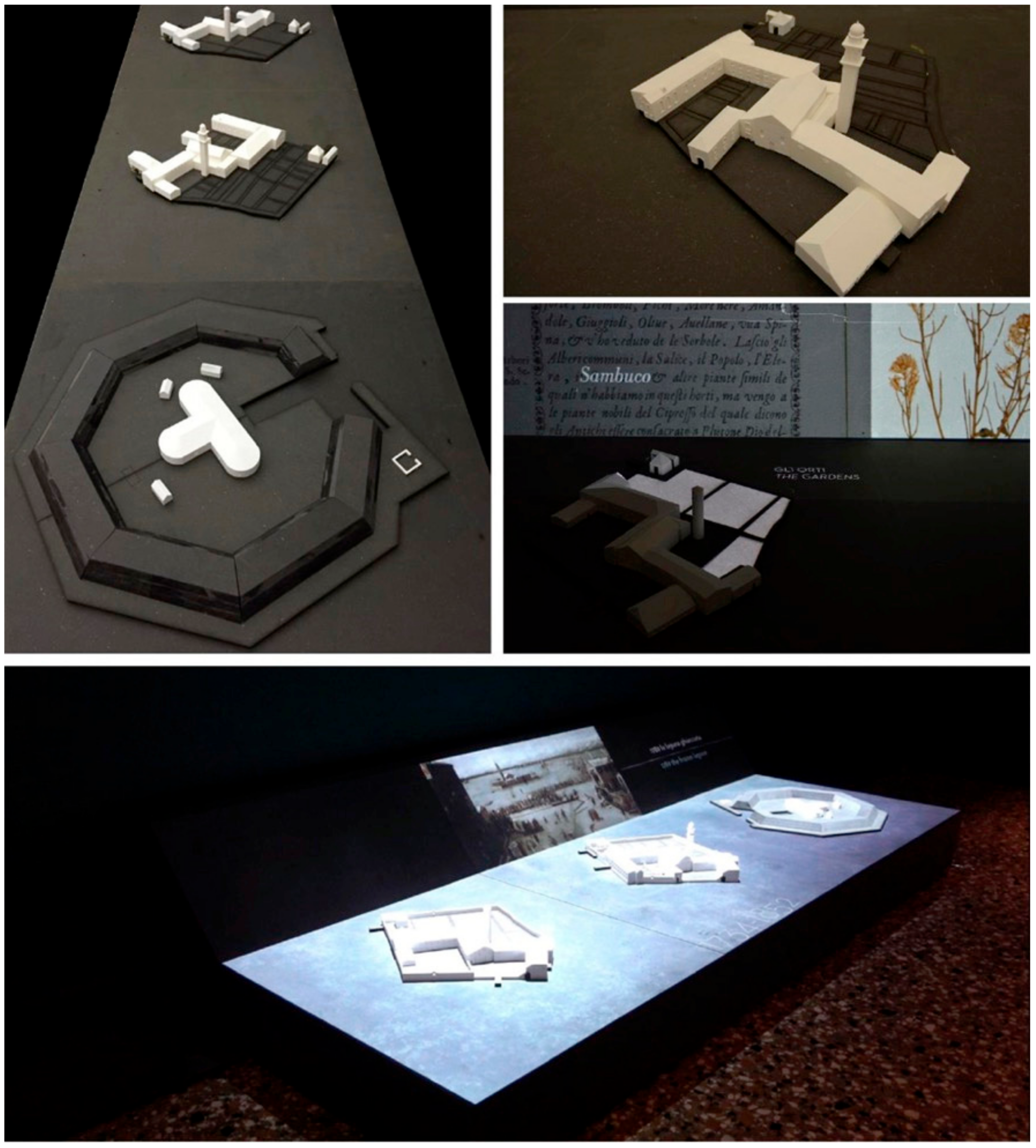
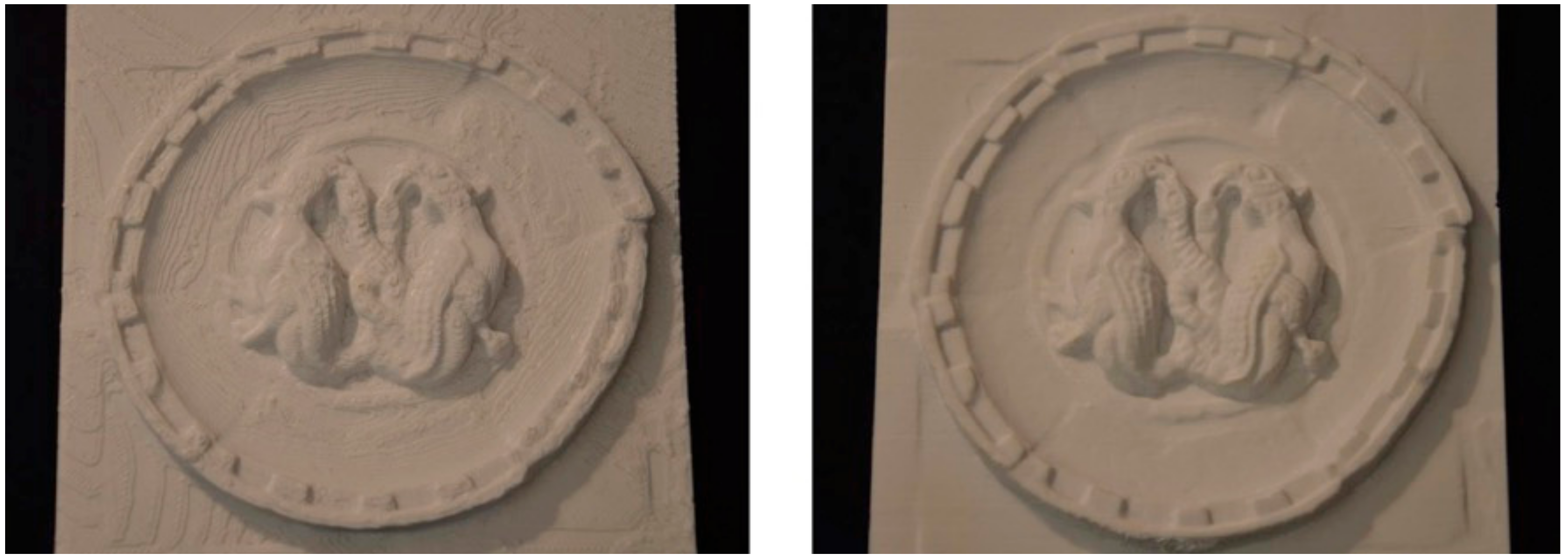
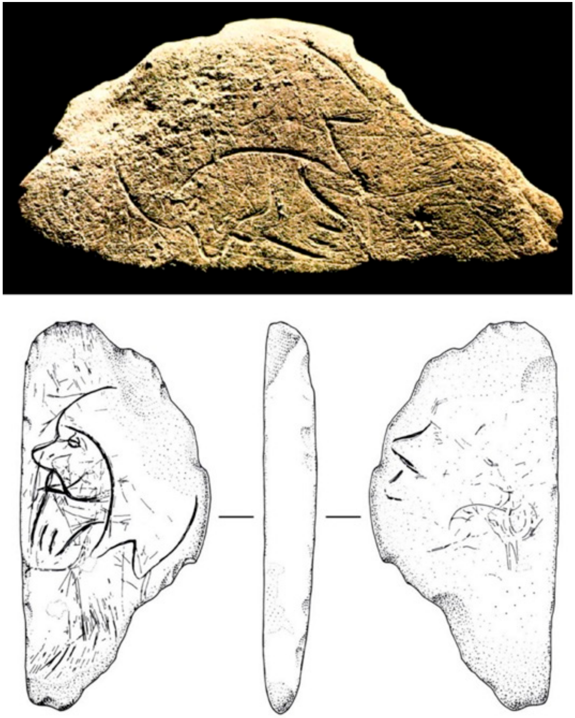
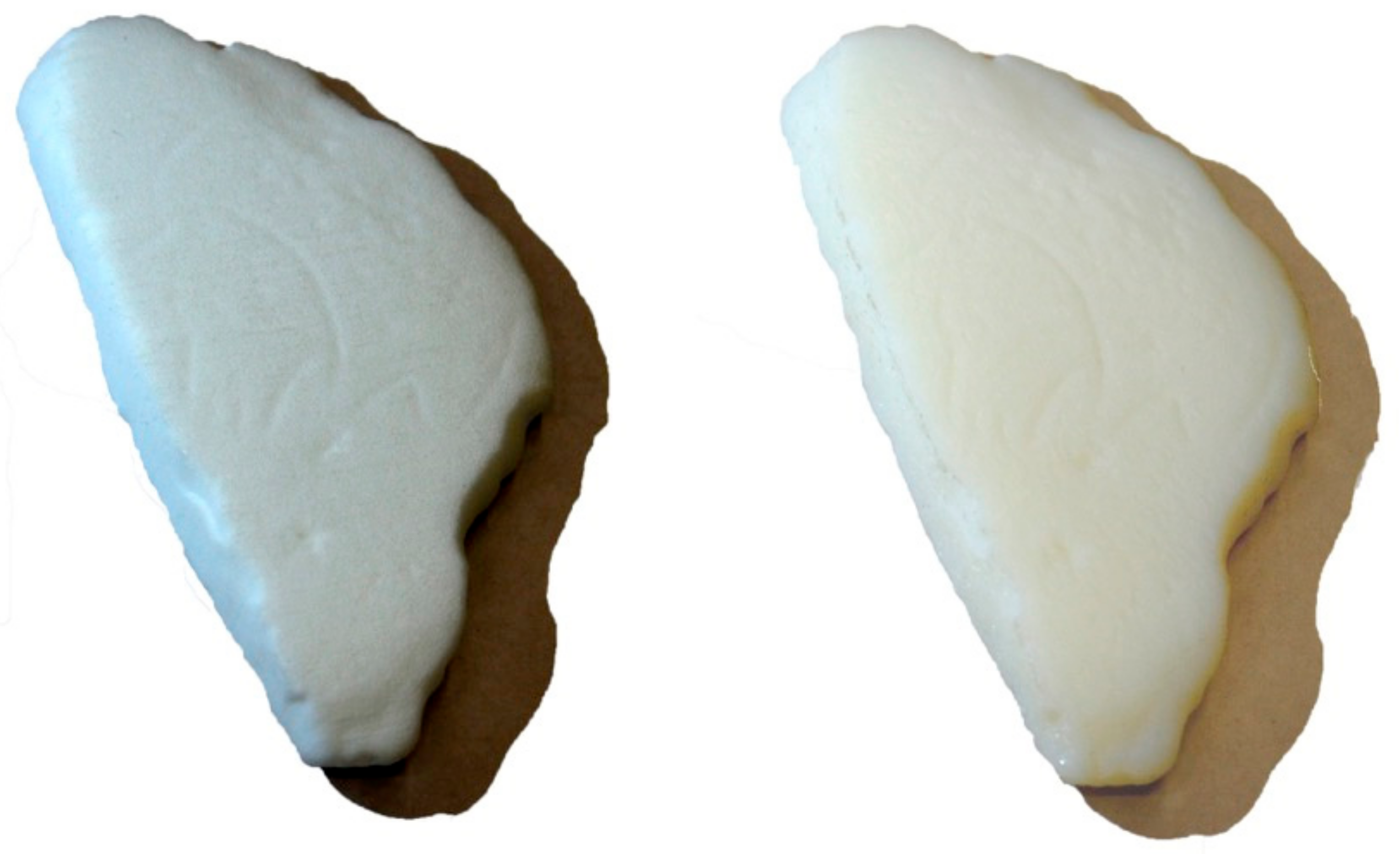
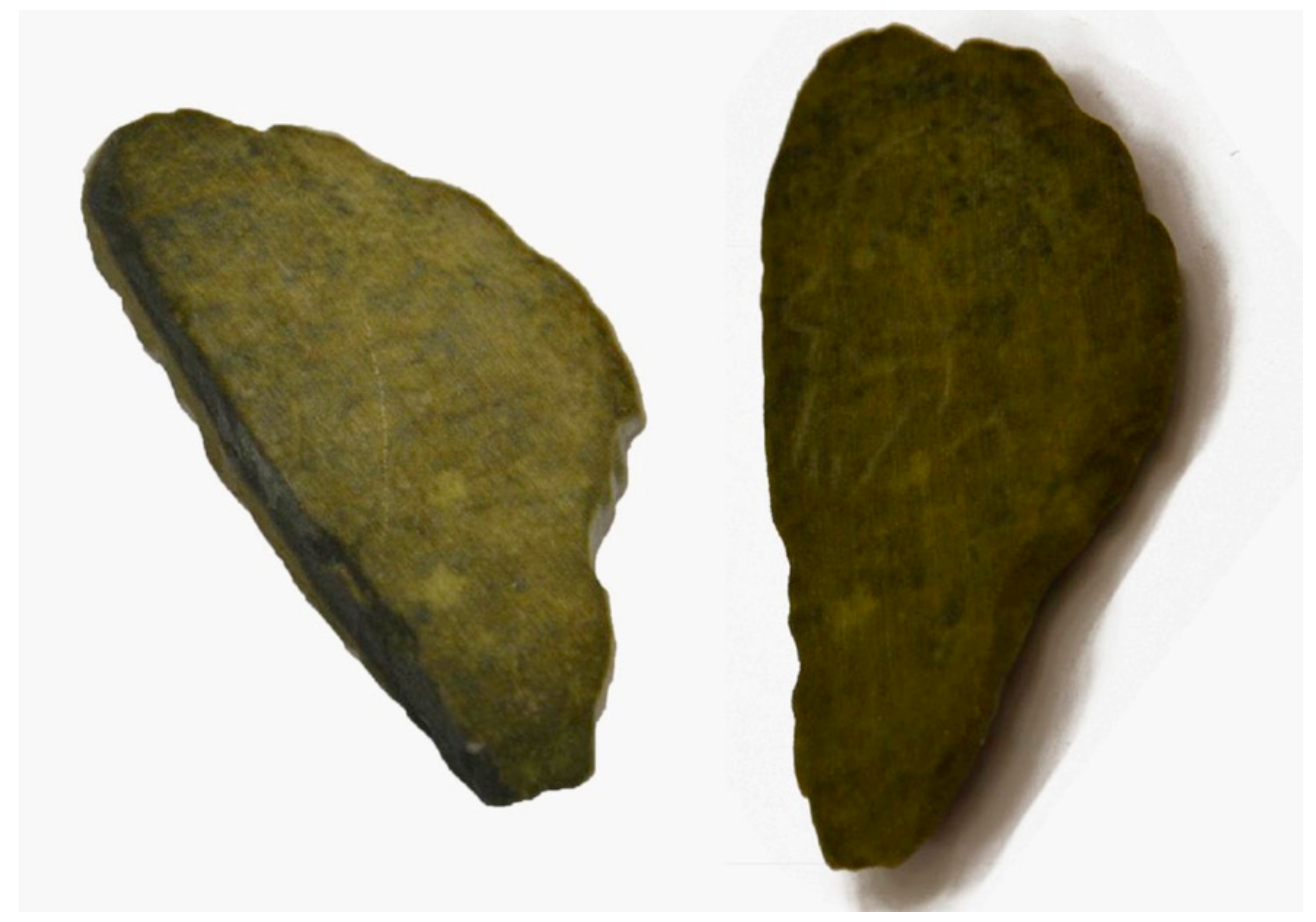
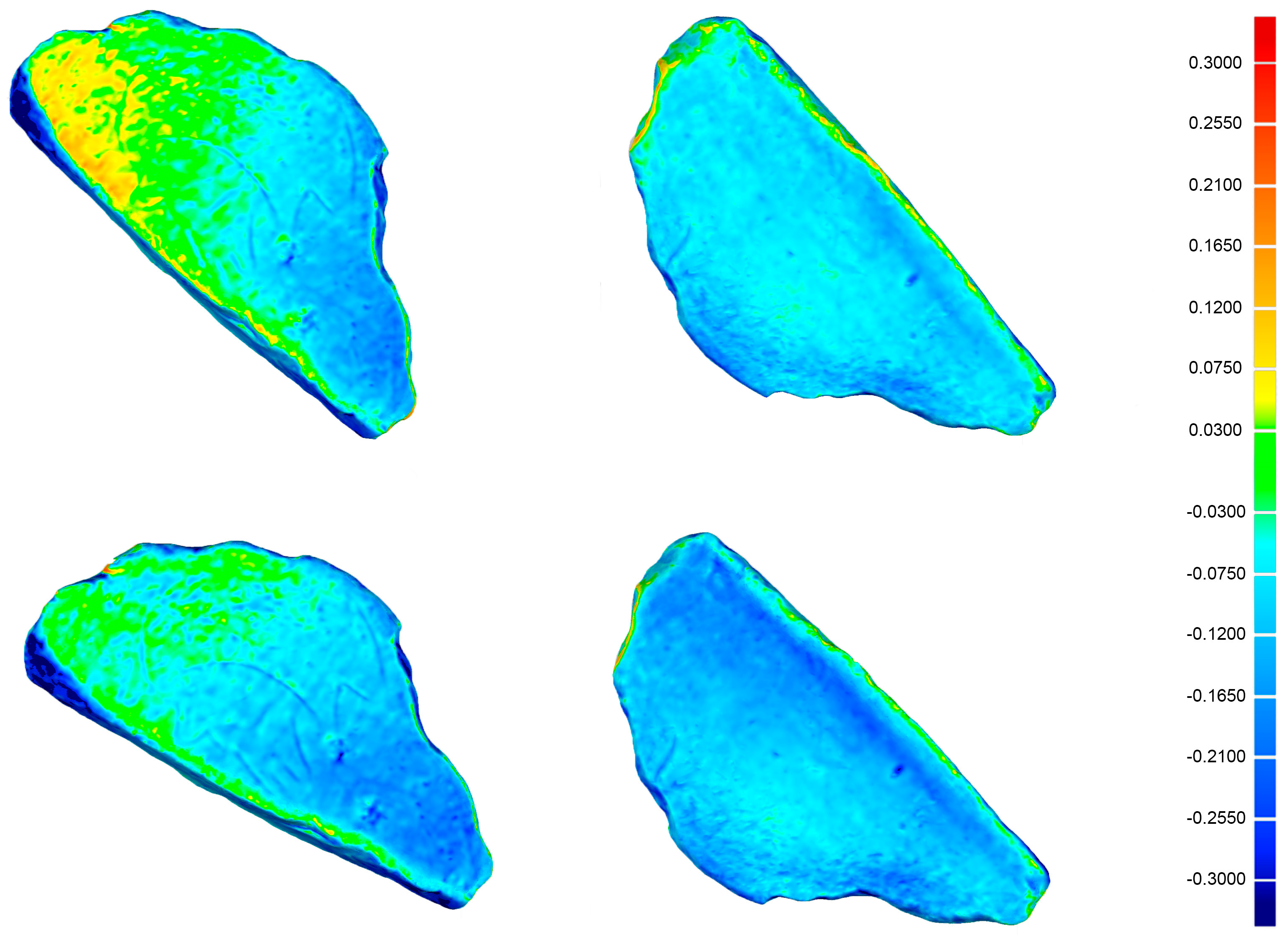
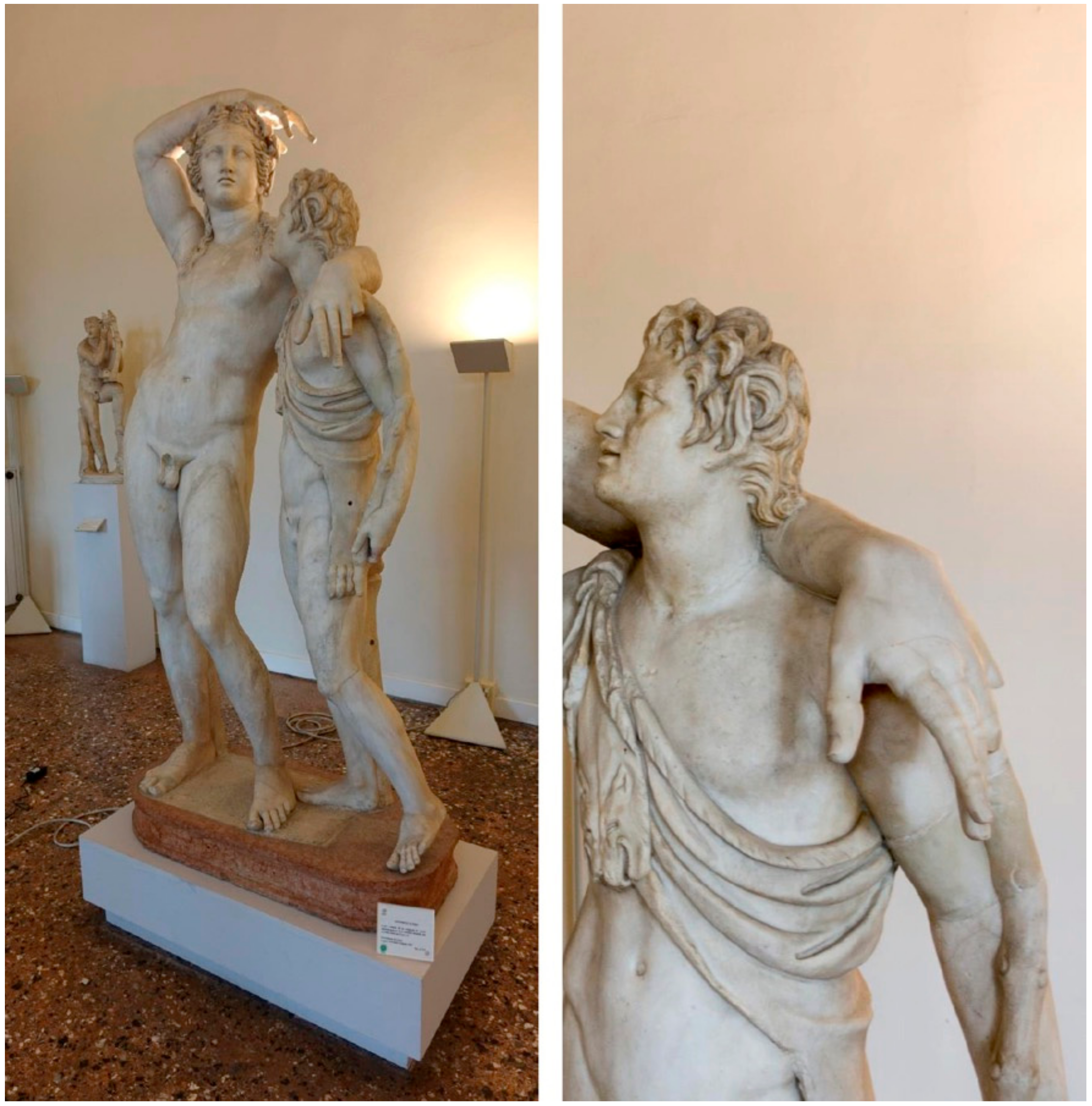
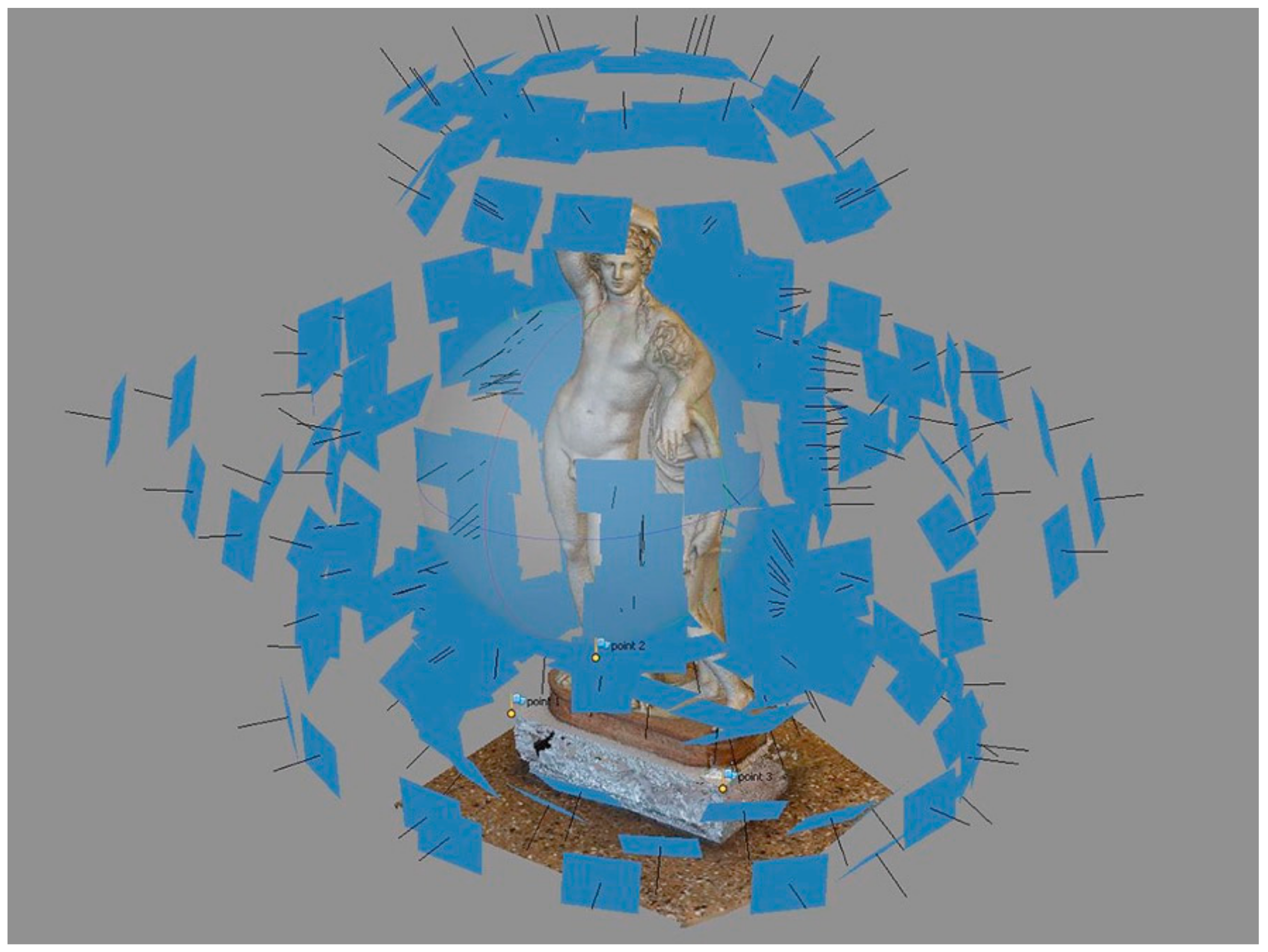
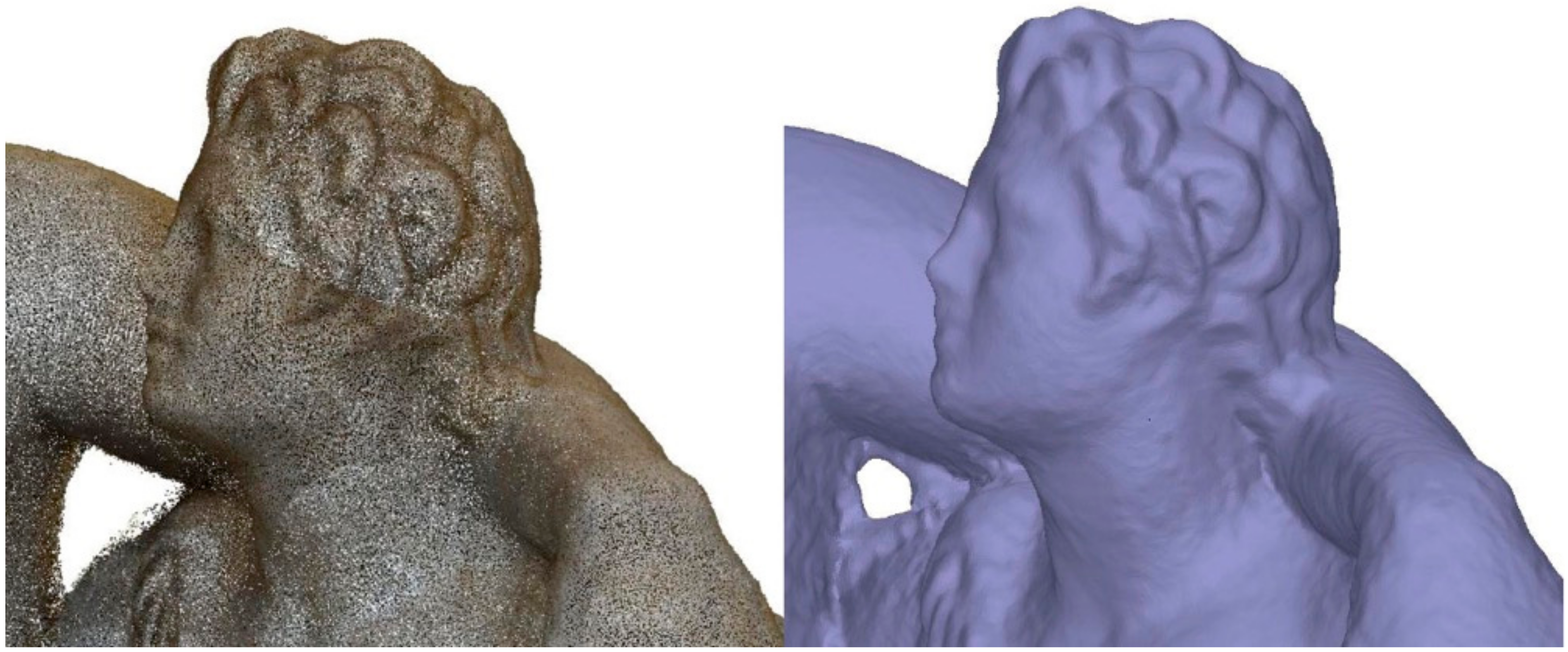
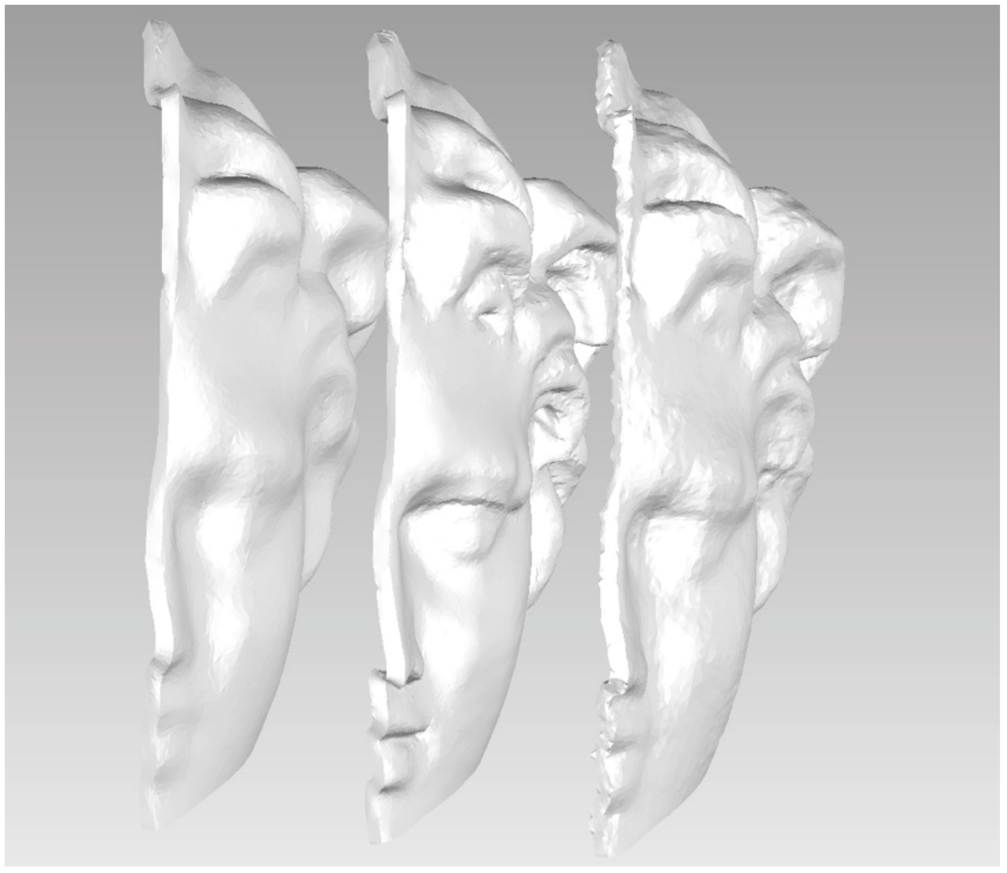
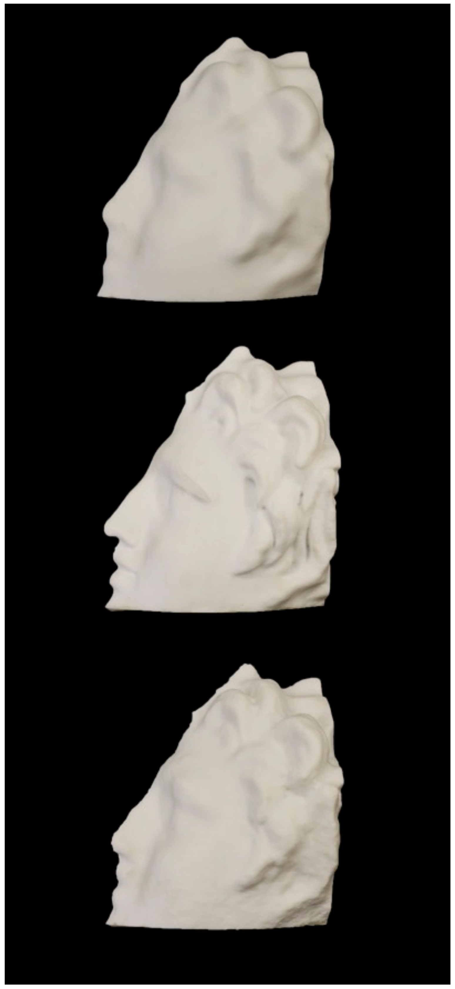
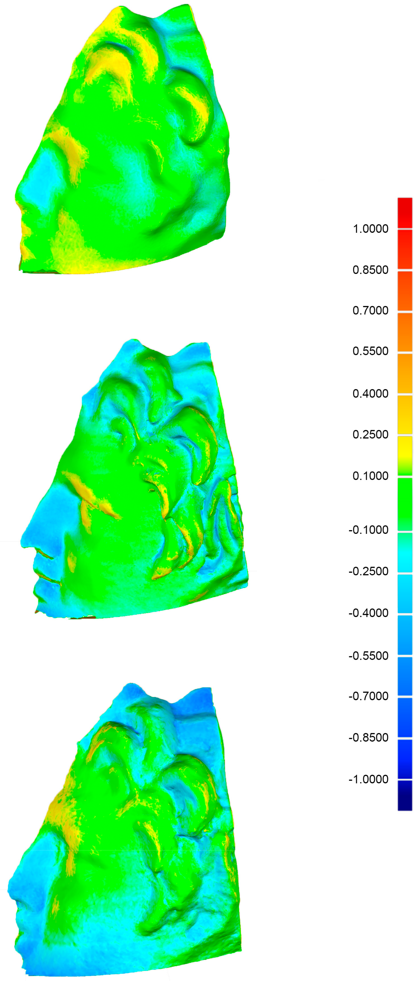
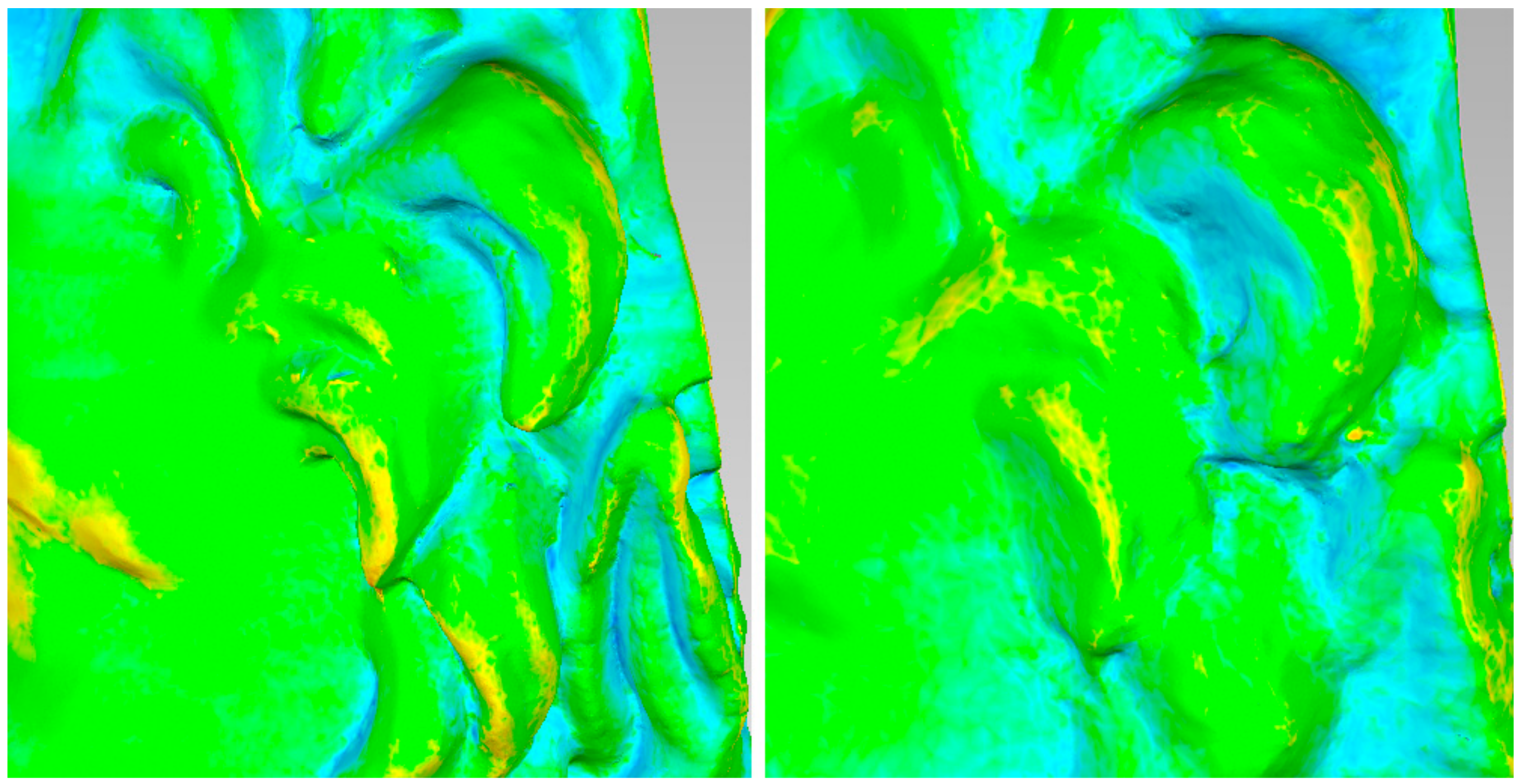
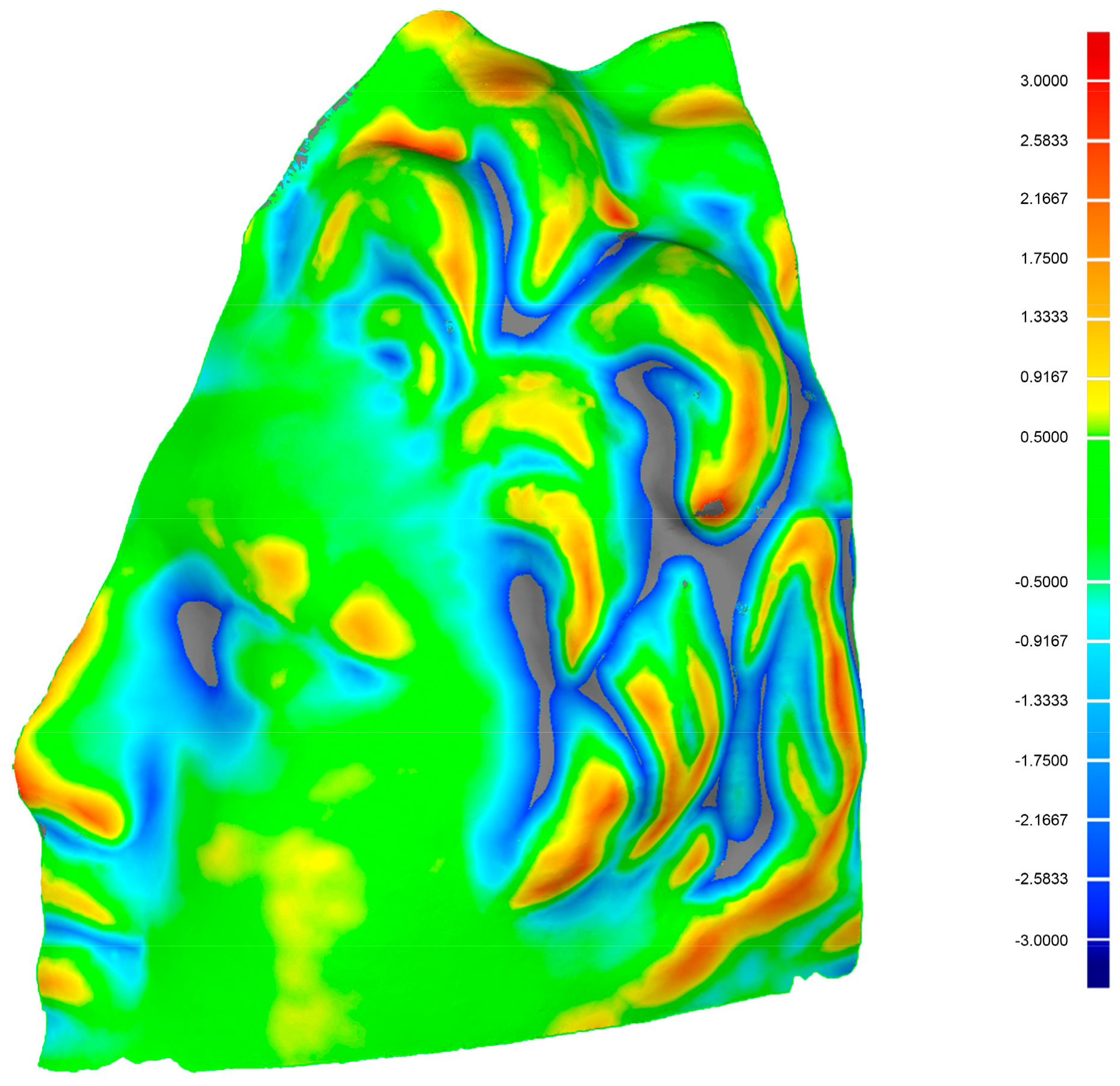
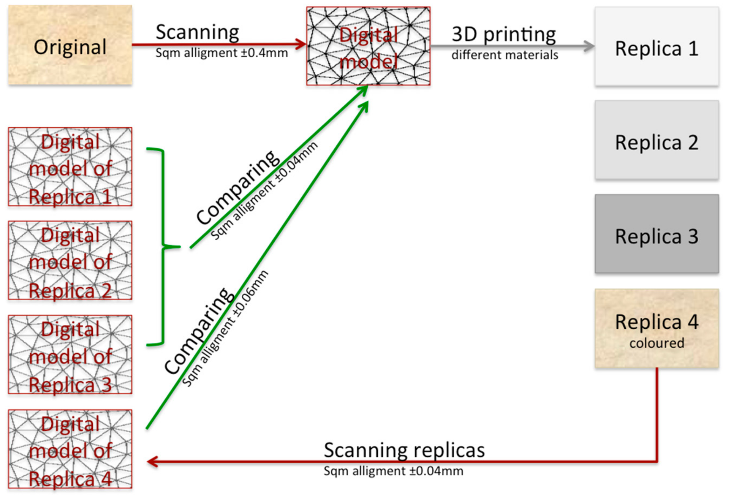
Table 1.
Technical characteristics of the two triangulation-based laser scanners.
| Instrument | Scanning Range (mm) | Accuracy (mm) | Maximum Scanning Size (mm) |
|---|---|---|---|
| Vivid 9i | 600–1000 500–2500 * (* extended mode) | ±0.008 Tele ±0.016 Medium ±0.032 Wide | Tele 463 × 347 × 680 * Med 823 × 618 × 1100 Wide 1495 × 1121 × 1750 * |
| Range 7 | 450–800 | ±0.040 | Tele 141 × 176 × 97 Wide 267 × 334 × 194 |
Table 2.
Statistical indices obtained as a result of global alignments of the three datasets.
| Object | Average Distance (mm) | Standard Deviation (mm) |
|---|---|---|
| Laser | 0.05 | ±0.06 |
| First Photogrammetry | 0.05 | ±0.10 |
| Second Photogrammetry | 0.05 | ±0.13 |
Table 3.
Statistical indices obtained from the comparisons between the printed models and the original data.
Table 3.
Statistical indices obtained from the comparisons between the printed models and the original data.
| Object | Maximum Distance (mm) | Average Distance (mm) | Standard Deviation (mm) |
|---|---|---|---|
| Laser | 1.428 | 0.130 | ±0.110 |
| First Photogrammetry | 0.753 | 0.097 | ±0.079 |
| Second Photogrammetry | 0.996 | 0.174 | ±0.133 |
Table 4.
Statistical indices obtained from the comparisons between the laser-scanning model and the photogrammetric ones.
Table 4.
Statistical indices obtained from the comparisons between the laser-scanning model and the photogrammetric ones.
| Compared Objects | Maximum Distance (mm) | Average Distance (mm) | Standard Deviation (mm) |
|---|---|---|---|
| Laser—First Photogram | 2.664 | 0.652 | ±0.581 |
| Laser—Second Photogram | 2.756 | 0.498 | ±0.537 |
© 2019 by the authors. Licensee MDPI, Basel, Switzerland. This article is an open access article distributed under the terms and conditions of the Creative Commons Attribution (CC BY) license (http://creativecommons.org/licenses/by/4.0/).
Share and Cite
MDPI and ACS Style
Balletti, C.; Ballarin, M. An Application of Integrated 3D Technologies for Replicas in Cultural Heritage. ISPRS Int. J. Geo-Inf. 2019, 8, 285. https://doi.org/10.3390/ijgi8060285
AMA Style
Balletti C, Ballarin M. An Application of Integrated 3D Technologies for Replicas in Cultural Heritage. ISPRS International Journal of Geo-Information. 2019; 8(6):285. https://doi.org/10.3390/ijgi8060285
Chicago/Turabian StyleBalletti, Caterina, and Martina Ballarin. 2019. "An Application of Integrated 3D Technologies for Replicas in Cultural Heritage" ISPRS International Journal of Geo-Information 8, no. 6: 285. https://doi.org/10.3390/ijgi8060285
Note that from the first issue of 2016, this journal uses article numbers instead of page numbers. See further details here.