Article

Distinguishing the Mélange-Forming Processes in Subduction-Accretion Complexes: Constraints from the Anisotropy of Magnetic Susceptibility (AMS)

1
Dipartimento di Scienze della Terra, Università di Torino, Via Valperga Caluso 35, 10125 Torino, Italy
2
Stogit Division, Snam S.p.A., Piazza Santa Barbara 7, 20097 San Donato Milanese, Italy
3
Dipartimento di Scienza ed Alta Tecnologia, Università degli Studi dell’Insubria, Via Valleggio 11, 22100 Como, Italy
*
Author to whom correspondence should be addressed.
Geosciences 2019, 9(9), 381; https://doi.org/10.3390/geosciences9090381
Submission received: 4 August 2019 / Revised: 28 August 2019 / Accepted: 29 August 2019 / Published: 31 August 2019
(This article belongs to the Special Issue Geology of Mélanges)

Abstract

:
The strong morphological similitude of the block-in-matrix fabric of chaotic rock units (mélanges and broken formations) makes problematic the recognition of their primary forming-processes. We present results of the comparison between magnetic fabric and mesoscale structural investigations of non-metamorphic tectonic, sedimentary, and polygenetic mélanges in the exhumed Late Cretaceous to early Eocene Ligurian accretionary complex and overlying wedge-top basin succession in the Northern Apennines (northwest Italy). Our findings show that the magnetic fabric reveals diagnostic configurations of principal anisotropy of magnetic susceptibility (AMS) axes orientation that are well comparable with the mesoscale block-in-matrix fabric of mélanges formed by different processes. Broken formations and tectonic mélanges show prolate and neutral-to-oblate ellipsoids, respectively, with magnetic fabric elements being consistent with those of the mesoscale anisotropic “structurally ordered” block-in-matrix fabric. Sedimentary mélanges show an oblate ellipsoid with a clear sedimentary magnetic fabric related to downslope gravitational emplacement. Polygenetic mélanges show the occurrence of a cumulative depositional and tectonic magnetic fabric. The comparison of field and laboratory investigations validate the analysis of magnetic features as a diagnostic tool suitable to analytically distinguish the contribution of different mélange forming-processes and their mutual superposition, and to better understand the geodynamic evolution of subduction-accretion complexes.

1. Introduction

Chaotic rock units, including mélanges and broken formations, are significant components of different modern and ancient subduction complexes around the world, showing different block-in-matrix fabrics that reflect a close relationship between the forming-process and the structural position acquired during their formation [1,2]. Highly sheared and disrupted tectonic mélanges and broken formations characterize the subduction plate boundary and/or associated megathrust shear zones, as well as out-of-sequence thrust faults in subduction complexes (e.g., [3,4,5,6,7,8,9,10]). Sedimentary mélanges or heterogeneous mass-transport deposits occur from slope instability in the upper part of frontal wedges of subduction–accretion complexes and in the trench inner-slope (e.g., [11,12,13,14,15,16,17,18,19,20,21,22,23,24,25,26,27,28]). Diapiric mélanges, including shale and mud diapirs, occur as the result of the upward rise of overpressured fluids migrating along the basal megathrust shear zone or channeled along megasplay faults (e.g., [29,30,31,32,33,34,35]). Each mélange type may subsequently be overprinted and structurally reworked by tectonic processes, such as shearing and tectonic mixing, during the evolution of the subduction complex, particularly when placed or recycled in the plate interface and/or involved within shear zones of (mega)thrust faults and splays, forming polygenetic mélanges (e.g., [26,34,36,37,38,39,40,41,42,43,44]). As a consequence, the primary internal block-in-matrix fabric of mélanges is commonly obscured and strongly reworked, hampering the recognition of their primary process of formation.
Although several helpful meso-to-mapscale structural criteria to distinguish chaotic rock unit types and related forming processes have been proposed and successfully applied on exhumed subduction–accretionary complexes on-land (e.g., [9,33,34,36,38,39,40,41,45,46,47,48,49,50,51,52,53,54,55,56,57,58,59,60,61]), they cannot be fully applied to modern subduction complexes offshore because of the extremely challenging conditions of drilling in oceanic trenches that are several kilometers deep. Cores offer only a limited scale of observation, which is not comparable with that of field observations. Moreover, the size and small scale of the diagnostic block-in-matrix fabric of chaotic rock units is well below the standard seismic resolution. Thus, the research and application of alternative analytical criteria to discriminate chaotic rock units and their forming processes are necessary and highly significant. The topic is critical, since the subduction of heterogeneous material, such as chaotic rock units and mass transport deposits, has been reported as a significant factor affecting seismic style within a subduction plate interface and subduction shear zones (e.g., [8,26,62,63,64]).
In this paper, we present the results of the comparison between magnetic (AMS—anisotropy of magnetic susceptibility) and mesoscale structural fabrics of non-metamorphic tectonic, sedimentary, and polygenetic chaotic rock units, including broken formations and mélanges, of the exhumed Ligurian accretionary complex and the overlying wedge-top basin succession in Northern Apennines (northwest Italy; Figure 1), which represent an ancient analogue for the shallow portion of present-day subduction complexes (e.g., [18,26,33,34,40]). Our findings demonstrate that the magnetic fabric reveals peculiar configurations of the principal susceptibility axes orientations for the different types of chaotic rock units, which are fully comparable with the different mesoscale organization of fabrics distinguished by field observation (see [33]). We refer to Festa et al. (2019; see reference [56]) for the used mélange terminology.

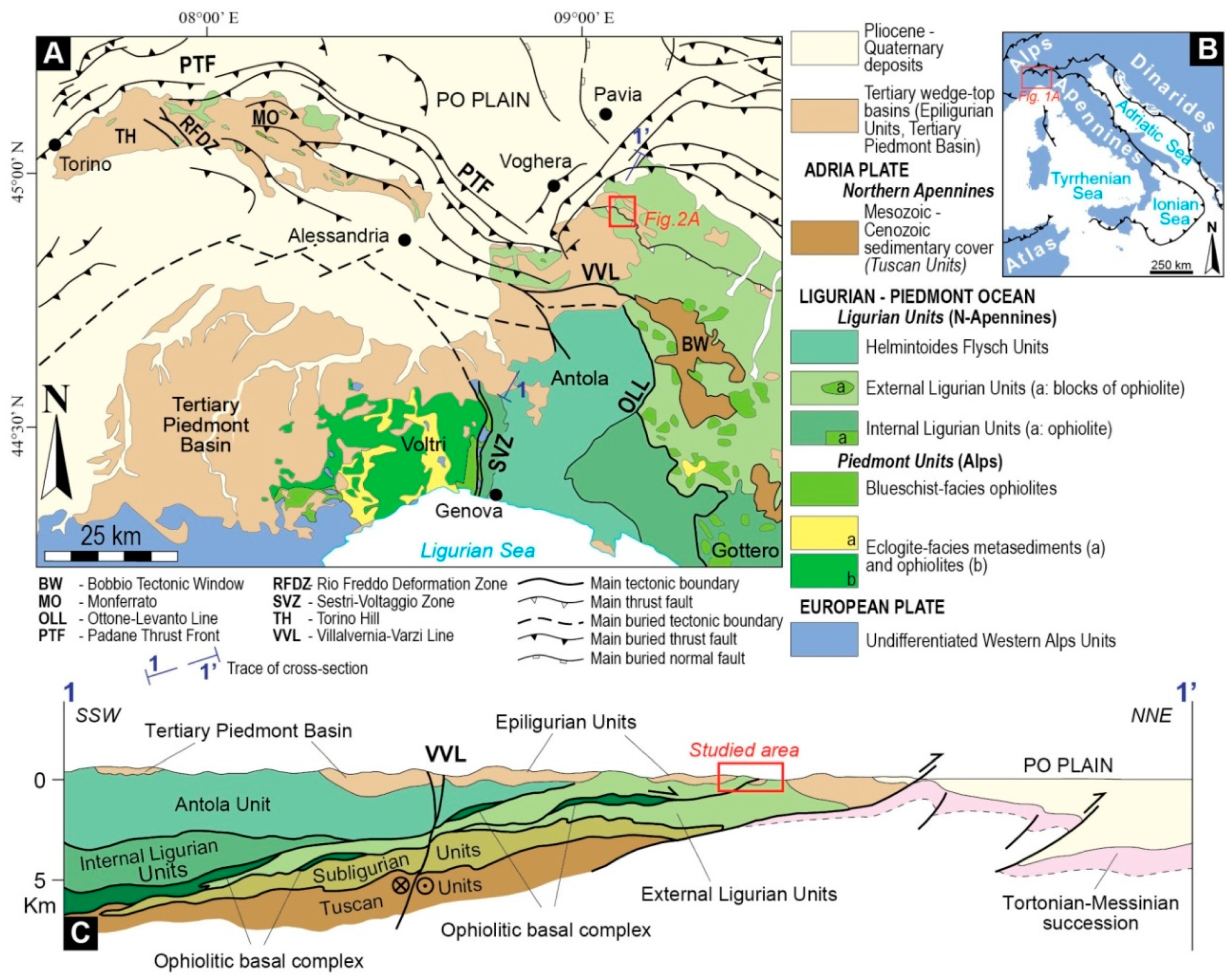
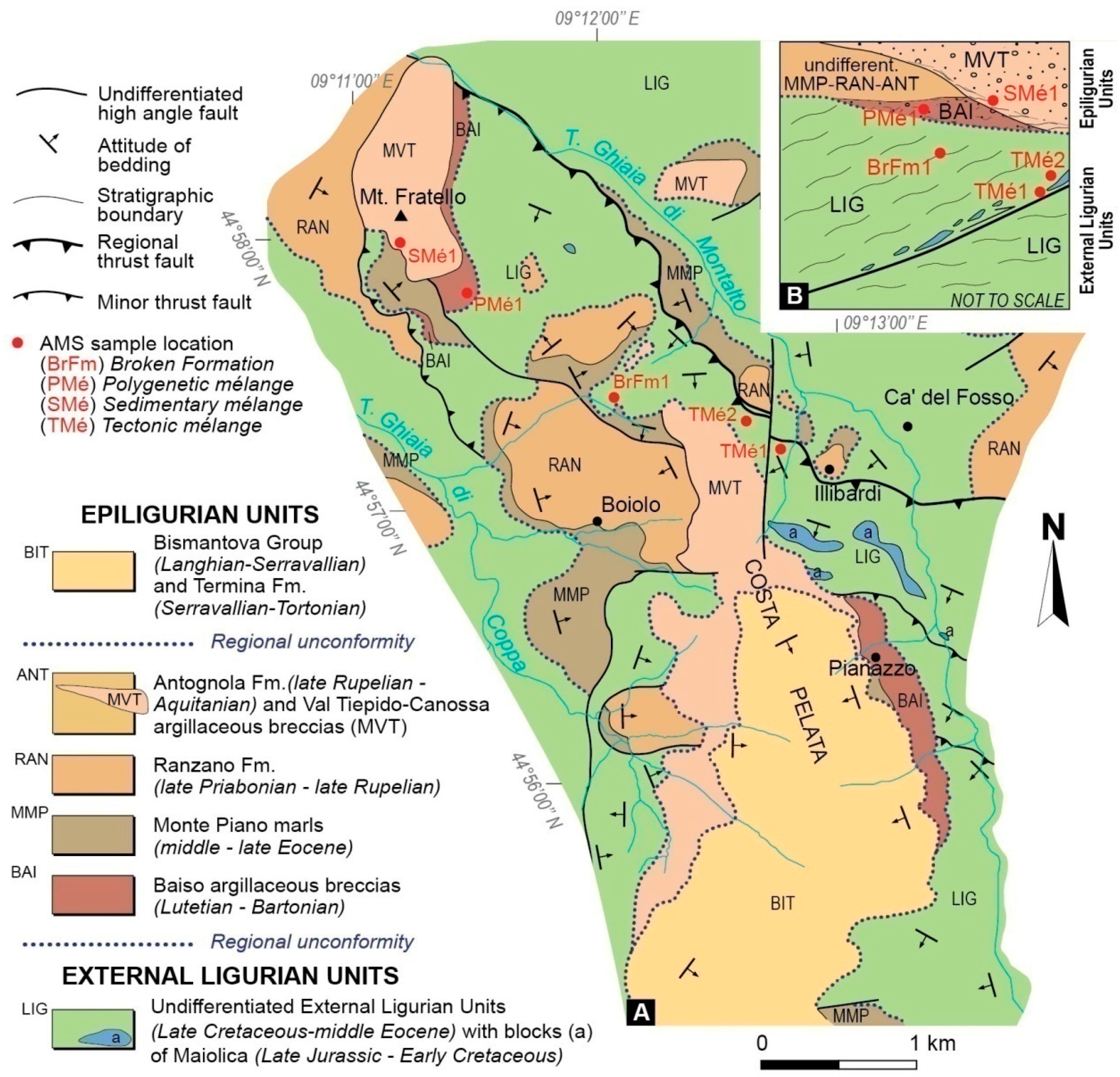
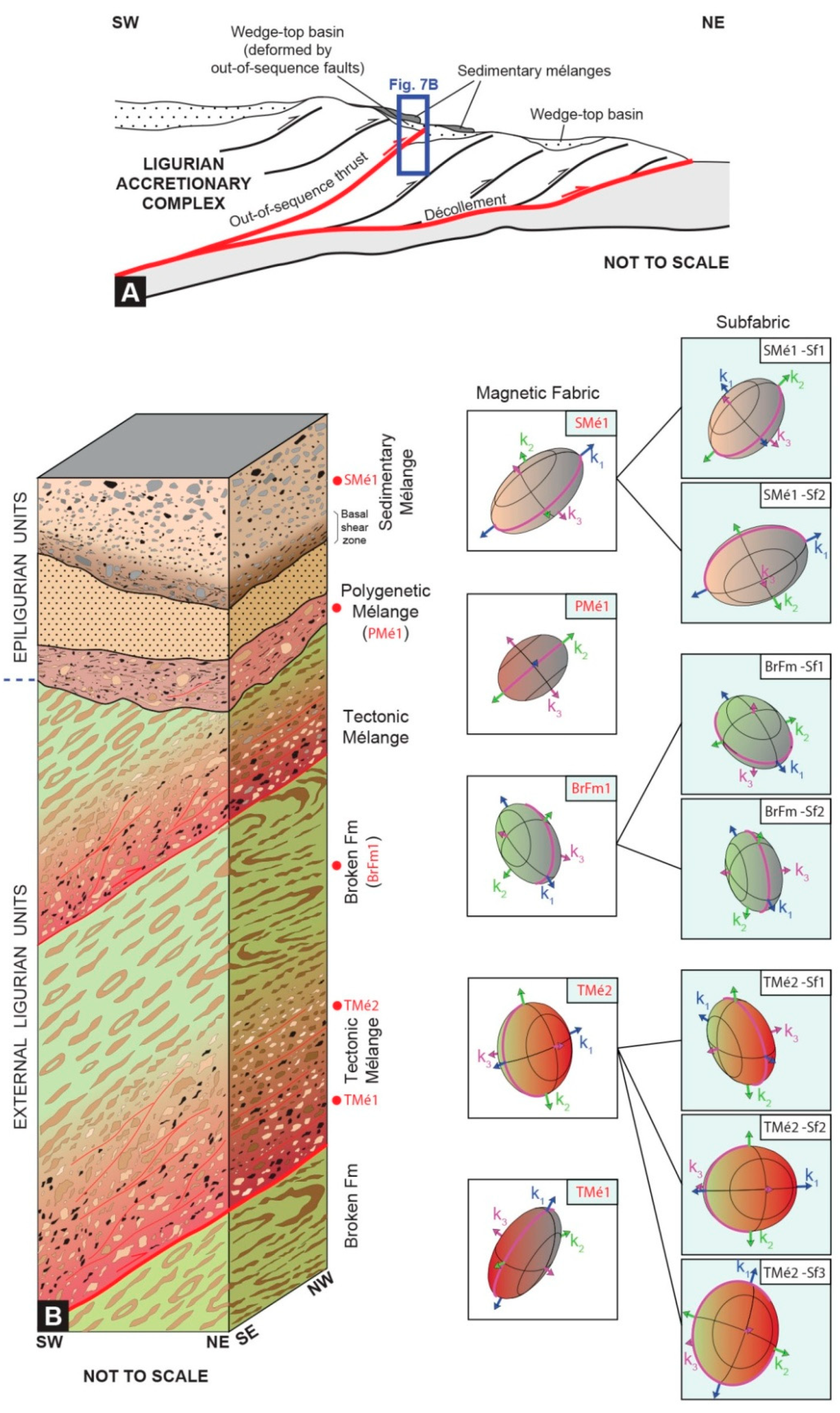
2. Geological Setting

The Northern Apennines (Figure 1) imbricate thrust stack represents a good ancient analogue of modern subduction-accretion complexes, resulting from the Late Cretaceous–Early Cenozoic convergence between the European continental margin and the Adria microplate that produced the Piedmont–Ligurian ocean closure (e.g., [65,66,67,68,69,70,71,72,73]).
The Late Cretaceous–Early Eocene accretionary stage has been recorded in the evolution of the Ligurian Accretionary Complex, which consists of different units (i.e., Internal, External, and Subligurian units; Figure 1) containing tectono-sedimentary assemblages originally deposited in an ocean basin (i.e., Jurassic ophiolites and sedimentary cover), ocean-continental transition (OCT) zone, and thinned continental crust of the Adria margin, respectively. During this stage, related to the east-dipping Alpine subduction, a consistent part of the External Ligurian units (i.e., the Basal complex Auct.) was strongly deformed, leading to the formation of different types of chaotic units (i.e., broken formations and tectonic mélanges) (e.g., [18,33,34,40,71,73,74,75,76,77,78]).
Since the middle–late Eocene, the wedge-top basin succession of the Epiligurian units unconformably covered the Ligurian accretionary complex and the north- to northeast-verging thrust-related structures, which formed during the west-dipping Apennine subduction of the thinned continental margin of Adria (e.g., [67,76]). Different types of mass-transport deposit (MTDs), including sedimentary mélanges (i.e., olistostromes), occur at different stratigraphic levels within the wedge-top basins succession, marking different stages of slope instability (e.g., [18,21,34,73,75,76,77,78,79,80,81,82,83,84,85,86,87]).
Figure 1. Structural sketch map (A) of the northwestern Italy (modified from [88] and [73]); (B) location of Figure 1A; (C) geological cross section across the Northern Apennines (modified from [89]).
Geosciences 09 00381 g001

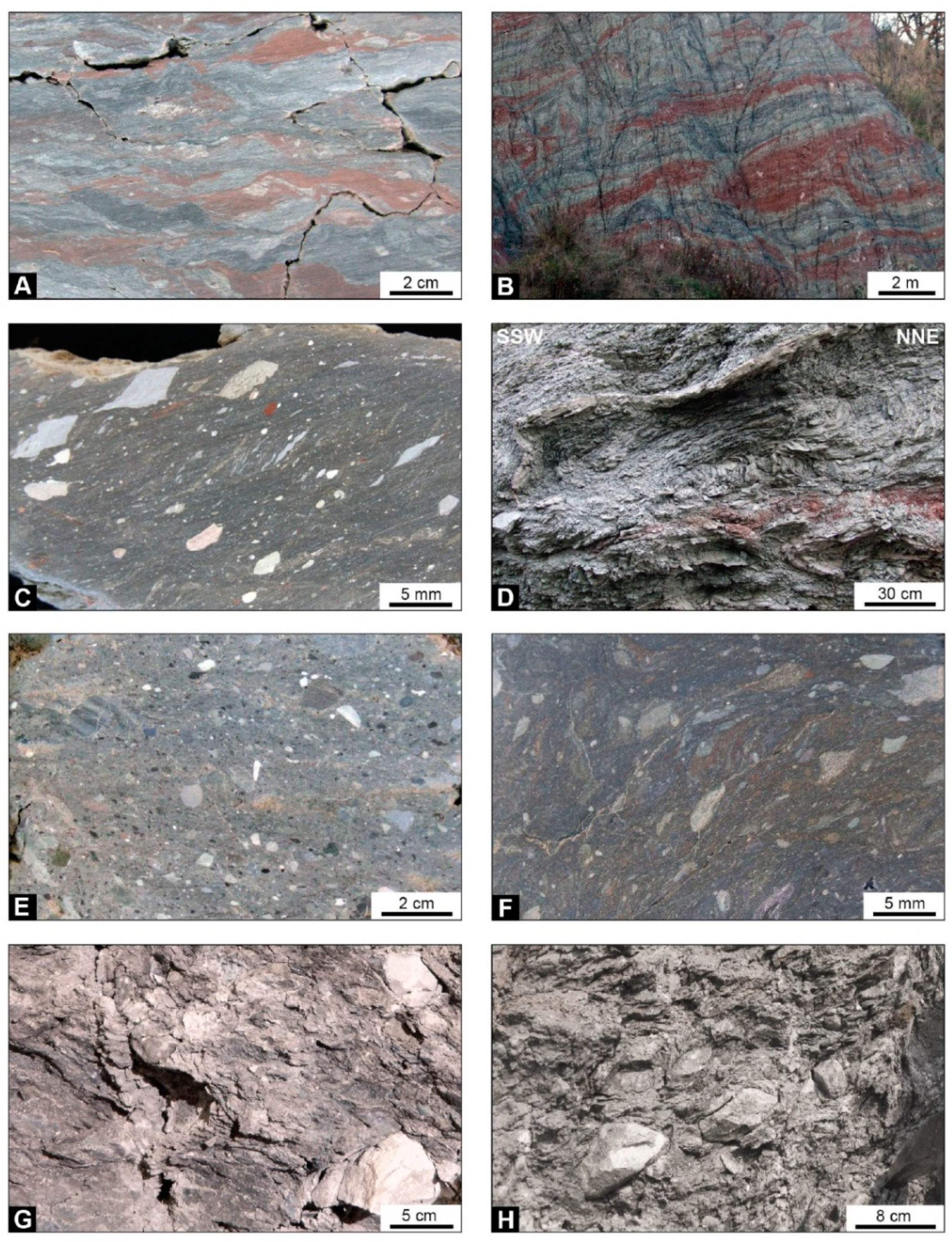
3. Meso-Structural Fabrics of Chaotic Rock Units

Four different types of chaotic rock units, part of which were described in previous published papers focusing on mélange-forming processes (see [33,87]), occur in different tectono-stratigraphic positions within the exhumed Ligurian accretionary complex and overlying wedge-top basins of the Epiligurian successions in the Voghera sector of the Northern Apennines (Figure 2A). Previously published structural data [33] are integrated by new ones, allowing for the discrimination of the process of formation of four types of chaotic rock units on the basis of their different meso-to-mapscale and micro-scale diagnostic block-in-matrix fabrics [56].

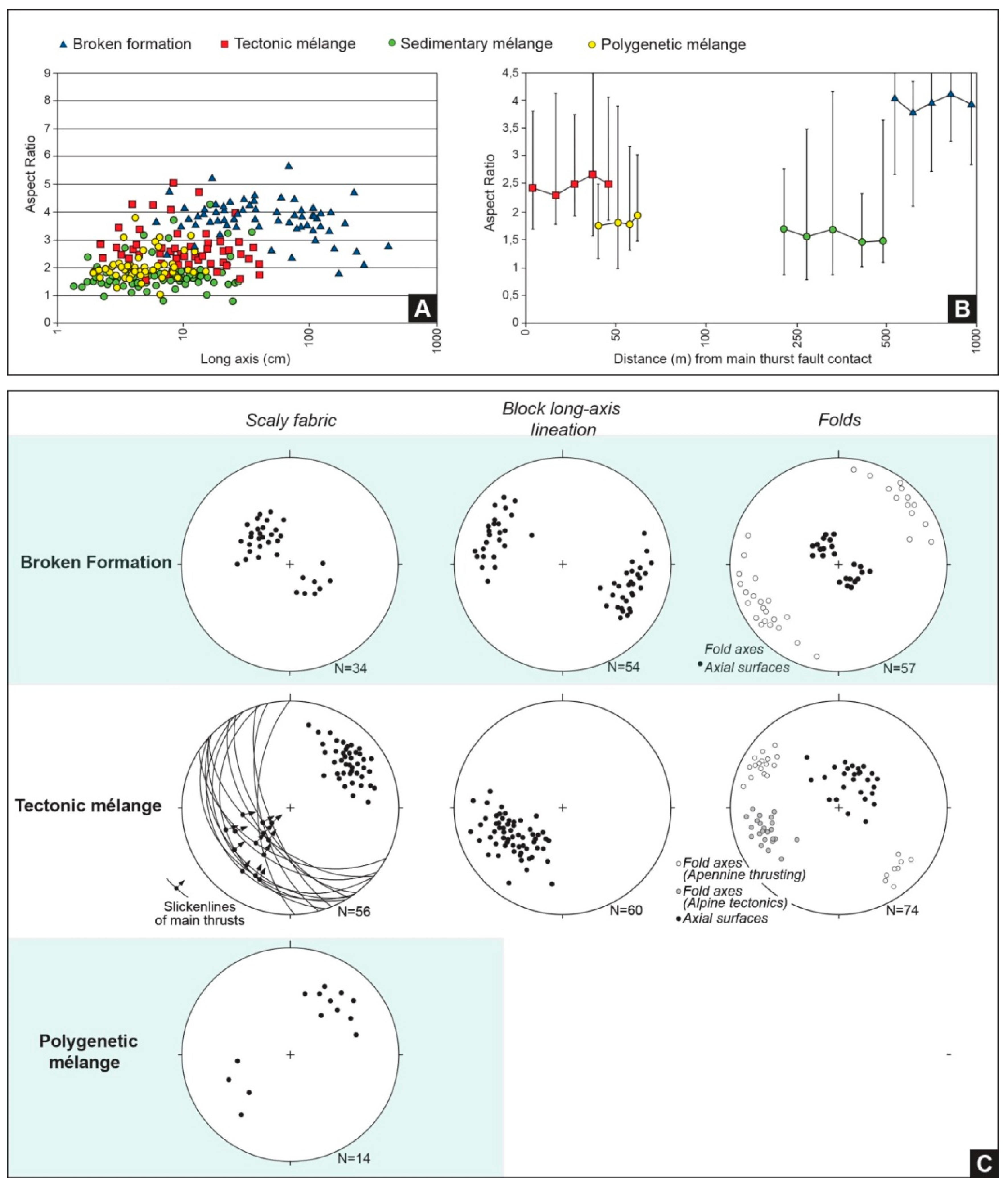
3.1. The Broken Formation

The broken formation (sensu [45]) corresponds to the Upper Cretaceous Argille varicolori of the External Ligurian units (Figure 2), which results from the fragmentation and disruption of an originally coherent well-bedded stratigraphic succession made of varicolored clay, shale, and marl, alternating with limestone, sandstone, and manganiferous siltstone in decimeter-thick beds. Its block-in-matrix fabric was mainly acquired through layer-parallel extension/contraction occurring at the wedge front of the Ligurian accretionary complex during the Late Cretaceous–middle Eocene oceanic subduction stage (e.g., [33,34,40,47,74,77,78]).
At the mesoscale, the broken formation is characterized by pinch-and-swell structures, necking of the less competent, shaly, clayey, and marly layers, and a brittle and/or ductile bedding-parallel boudinage of centimeter- to meter-long elongated and mainly tabular bed fragments, which represent “native” (i.e., intra-formational) blocks (Figure 3A). Elongated blocks display a high aspect ratio (block long axis/short axis) with a mean value ranging from 3.7 to 4.2 (Figure 4A,B). Pinch-and-swell and boudinage structures are mainly asymmetric, defining a planar alignment that is consistent with extensional shearing in an east-southeast–west-northwest direction, as documented by the block long-axis lineation to the same direction (Figure 4C). Boudins are aligned parallel to the shaly and marly layers (i.e., the matrix) in defining a typical pseudo-bedding fashion (Figure 3A).
Meter-scale disharmonic-to isoclinal and rootless to transposed intra-layer sheath-like folds deform the broken formation (Figure 3B). They show sub-horizontal axial surfaces (Figure 4C), northwest and/or southeast-dipping, irregularly thickened and stretched hinge zones, and thinned and boudinaged limbs parallel to the southeast (or northwest)-dipping pseudo-bedding.
The block-in-matrix fabric of the broken formation indicates that deformation started just after the deposition of sediments under unconsolidated to poorly-consolidated conditions, and continued throughout progressive lithification [33,34]. Vertical compaction due to burial resulted in the formation of layer-parallel deformation, which is consistent with large-magnitude lateral spreading that resulted in flattening (mean aspect ratio from 3.7 to 4.2; see [34]). The coeval development of flattened structures and intra-layer sheath-like folds was commonly interpreted as the product of heterogeneous deformation at the toe of the accretionary wedge, where different deformational domains can exist (e.g., [34,90]).

3.2. The Tectonic Mélange

Close to the main regional thrust surface (Figure 2), the northeast-verging thrusting-related tectonic shearing formed a tens of meters thick shear zone. It is characterized by a block-in-matrix fabric consisting in the tectonic mixing of the broken formation (i.e., the Argille varicolori), and “exotic” elongated blocks, tens to hundreds of meters long, which represent wrenched fragments of both the hanging wall and footwall units succession (see [33,82]). Thus, the final block-in-matrix fabric of the tectonic mélange represents the product of the superposition of two different tectonic events.
“Exotic” blocks, lenticular to elongated in shape, have their northeast-striking long axes aligned parallel to the verging of the regional thrusting event and of mesoscale shear zones (Figure 2 and Figure 3C). The mean values of their aspect ratio range from 2.3 to 2.7 (Figure 4A,B). The long-axes of the blocks embedded in the matrix are reoriented by P and R, S-C and P-C shear zones and display a strong alignment to tectonic features at all scales (Figure 4C), from millimeter-size clasts to decimeter-sized blocks. The shaly matrix is strongly affected by southwest dipping R and P shears, whose mutual interlacing define millimeter- to centimeter-scale, spaced lenticular lenses (L shear lenses, sensu [91]), which are wrapped by northeast-verging shear surfaces. The lenses are commonly included within pervasive decimeter- to meter-wide S-C reverse shear zones, with northwest strikes and west-southwest dip directions that are also responsible for their reorientation.
The shear transposition of the previously-formed mesoscale isoclinal folds of the broken formation (northwest- to southeast-oriented) produced isolated and sheared fold hinges, with axial surfaces aligned to northeast-verging shear planes of the tectonic mélange (Figure 3D). The isolated folds of the broken formation thus show northeast-verging and mainly northwest- and locally southeast-plunging fold axes (Figure 3C; see also [33]).
Away from the thrust faults (Figure 2), the intensity of thrust-related deformation gradually decreases, allowing a transition to the tectonic pseudo-bedding of the broken formation and/or to the original (partially preserved) bedding.
The final block-in-matrix of the tectonic mélange has been interpreted as being related to the northeast-verging out-of-sequence thrusting in the inner wedge of the Ligurian accretionary complex, during the late Oligocene–early Miocene collisional stage (e.g., [18,32,80,84]). Exotic blocks offscraped from the footwall unit were accreted within the thrust shear zone and mixed with native blocks derived from the earlier broken formation.

3.3. The Sedimentary Mélange

The sedimentary mélange (Figure 2), corresponding to the upper Oligocene–lower Miocene Val Tiepido Canossa Argillaceous Breccias (see [83]), consists of an irregularly shaped chaotic mass-transport deposit, up to 180–200 m thick, which is internally characterized by a block-in-matrix fabric. The latter results from submarine cohesive debris flows that involve heterogeneous material sourced from the wedge of the Late Cretaceous Ligurian accretionary complex and disrupted portions of middle Eocene–Oligocene Epiligurian succession in response to out-of-sequence thrusting and the dynamic re-equilibrium of the wedge front during the collisional stage (e.g., [8,87]). The mass-transport deposit consists of the stacking of different single debris flow, ranging from meters to tens of meters in thickness [87]. Each single debris flow shows the inverse grading of the largest blocks, which range in size from decimeters to about 1 m, and are bounded at the base by decimeter-thick shear zones (see below).
At the mesoscale, the block-in-matrix fabric of the sedimentary mélange shows an isotropic fabric defined by the highly-disordered distribution and orientation of a polymictic assemblage of irregularly-shaped (angular to rounded) hard to partially-softclasts/blocks, dispersed in a brecciated shaly matrix (Figure 3E). The clasts/blocks, which range in size from centimeters to- decimeters and show different ages and origins, display a low aspect ratio, with a mean value ranging from 1.4 to 1.7 (Figure 4A,B).
The base of the sedimentary mélange and of each single debris flow is characterized by a thin horizon (5 cm to 50 cm in thickness) of sheared argillaceous breccias (Figure 2B and Figure 3F; see [25,87]).
This sheared horizon, which is interpreted to be formed as the result of the mass-transport emplacement (see [21,25,34,87,92]), shows a planar anisotropy defined by the alignment of elongated blocks parallel to the extensionally sheared layers and is crosscut at low angles by disjunctive extensional shear surfaces (Figure 3F). Poorly-consolidated clasts commonly display extreme elongation in the direction of emplacement, with asymmetries related to simple shear [87].
The random and highly-disordered distribution of the blocks in the shaly brecciated matrix (Figure 3E,F) suggest mechanisms of translation and emplacement related to the rheological behavior of a viscous matrix [93,94,95]. The basal and internal shear zones, which are characterized by enhanced reorientation of clasts and microclasts, matrix banding, and crude foliation, suggest a constriction plus flattening-type (i.e., prolate plus oblate) strain ellipsoid, with a prevailing component of stretching along the direction of flow and a minor component of planar flattening (see [92]). This agrees with a mechanism of emplacement likely related to “viscous” shear zones in a shale-dominated matrix, which is consistent with relatively slow-moving bodies [87].

3.4. The Polygenetic Mélange

The polygenetic mélange, which corresponds to the late Lutetian–early Priabonian Baiso argillaceous breccias (Figure 2) at the base of the Epiligurian succession (see [83]), differs from the Sedimentary mélange because its primary gravitationally-related block-in-matrix fabric is gently overprinted by tectonic deformation related to the late Oligocene–early Miocene northeast verging thrusting stage (see [33] for details). The primary block-in-matrix fabric of the mass transport deposits is well comparable with that of the sedimentary mélange, consisting in sub-angular to angular, and tabular clasts and blocks, centimeter- to decimeter in size, embedded in a brecciated shaly matrix (Figure 3G). However, partially elongated blocks also occur. Differently from those of the sedimentary mélange, blocks display a low to medium aspect ratio with a mean value ranging from 1.7 to 2.0 (Figure 4A,B). The matrix consists of polymictic and isotropic mud breccias with mainly rounded-to-angular and rarely elongated, millimeter-to-centimeter-sized clasts (Figure 3G,H). Independently on the scale of observation, the block-in-matrix fabric is gentle reoriented and close to minor thrust faults and shear zones, tabular blocks/clasts are aligned to pervasive S-C shears and scaly fabric, and southwest dipping and northeast verging, that overprint the originally formed mass-transport deposit (Figure 3H and Figure 4C).

4. Methods

One hundred and eleven specimens for AMS measurements were obtained in five selected sites (6 dm3 oriented hand sample) from the shaly, clayey, and marly matrix of the different types of chaotic rock units described above (Figure 2). Samples resulted by pressing plastic non-magnetic cubes (8 cm3 volume) into the wet matrix of oriented hand-samples, obtaining homogeneous specimens from heterogeneously chaotic (block-in-matrix) units.
Low-field magnetic susceptibility and its anisotropy (AMS) were measured at room temperature for all specimens using a Kappabridge KLY-3 (sensitivity of 2 × 10⁻⁸ SI), at the Centro Interuniversitario di Magnetismo Naturale (CIMAN-ALP, Peveragno, Italy). Then, Jelinek (1977, [96]) statistics for calculation of mean principal susceptibility axes, confidence ellipses with 95% of likelihood, and associated parameters were performed by the software ANISOFT [97] to reconstruct the magnetic fabric [98]. During the AMS analysis, we discarded a few significant outliers of large magnitudes and orientations that strongly deflected the mean tensor.
IRM (isothermal remanent magnetization) acquisition experiments and the Unmixing analysis (MAXUnMix software; [99]) revealed the occurrence of low-coercivity magnetic phases, which could be identified as magnetite/maghemite with different grain-size.
The magnetic fabric of a rock, geometrically modelled as a tri-axial ellipsoid (k1 ≥ k2 ≥ k3), depends on the amount, relative abundance and spatial distribution of its para-and ferro-magnetic minerals [100,101]. In the following, the shape of the magnetic ellipsoid of different types of chaotic rock units have been described through the ratios between the magnitude of the principal susceptibility axes, such as the magnetic lineation (L = k1/k2), the magnetic foliation (F = k2/k3), and the shape parameter, T = 2 ln ( k 2 / k 3 ) / ln ( k 1 / k 3 ) 1 , which also define its oblateness/prolateness [102]. The corrected anisotropy degree, Pj = exp 2 i = 1 3 ( ln k i ln k m ) 2 , expresses the eccentricity and stretches of the AMS ellipsoid [102].
On the basis of the shape of the AMS ellipsoid and its axes orientation [101,103,104,105], it is possible to discriminate sedimentary from tectonic magnetic fabrics, which also reflect the emplacement mechanisms and the deformation processes that have affected rocks (see Supplementary Material Figure S1).
The sedimentary fabric, either purely depositional or related to compaction, is characterized by an oblate ellipsoid (k1 ≈ k2>> k3; 0 < T ≤ 1; F > L) showing a well-defined bedding-parallel magnetic foliation, typical of MTDs and/or sedimentary mélanges [54], and a poorly defined magnetic lineation or eventually a k1 cluster consistent with paleo-current directions.
The tectonic fabric displays different shapes of the AMS ellipsoid according to the magnitude of the tectonic deformation, ranging from prolate (k1>> k2 ≈ k3; −1 ≤ T < 0; L > F) in the case of incipient deformation, to oblate with schistosity-parallel magnetic foliation in case of strong tectonic overprinting. In particular, depending on the strain rate during deformation, the k1 axis is oriented perpendicular (i.e., parallel to intersections between S and C planes or thrust-related fold axes) or parallel to the shear direction [106] showing a progressive clustering of k1 axes in the direction of maximum stretching and k3 axis toward the maximum compressive stress direction.
We used the contour diagram for the principal susceptibility axes distribution for isolating the AMS contribution of subfabrics, if any (e.g., primary sedimentary fabric from tectonic fabric) [101,103,104,105,107,108,109,110]. As a matter of fact, subfabrics, due to distinct processes or events, may be expressed in different mineral and/or grain-size fractions and are superposed in the conventionally observed AMS [103].

5. AMS Results and Magnetic Fabric of Chaotic Rock Units

Results revealed low magnetic susceptibility values from 56 to 236 μSI (Table 1), suggesting a dominant control of the paramagnetic minerals on the magnetic fabric [104]. The standard deviation of the mean susceptibility is relatively low (5–25%), and this is considered as an evidence of specimen homogeneity. Also, Pj values are low, ranging about from 1.007 up to 1.088, with low standard deviation values (0.001–0.018) (Table 1).

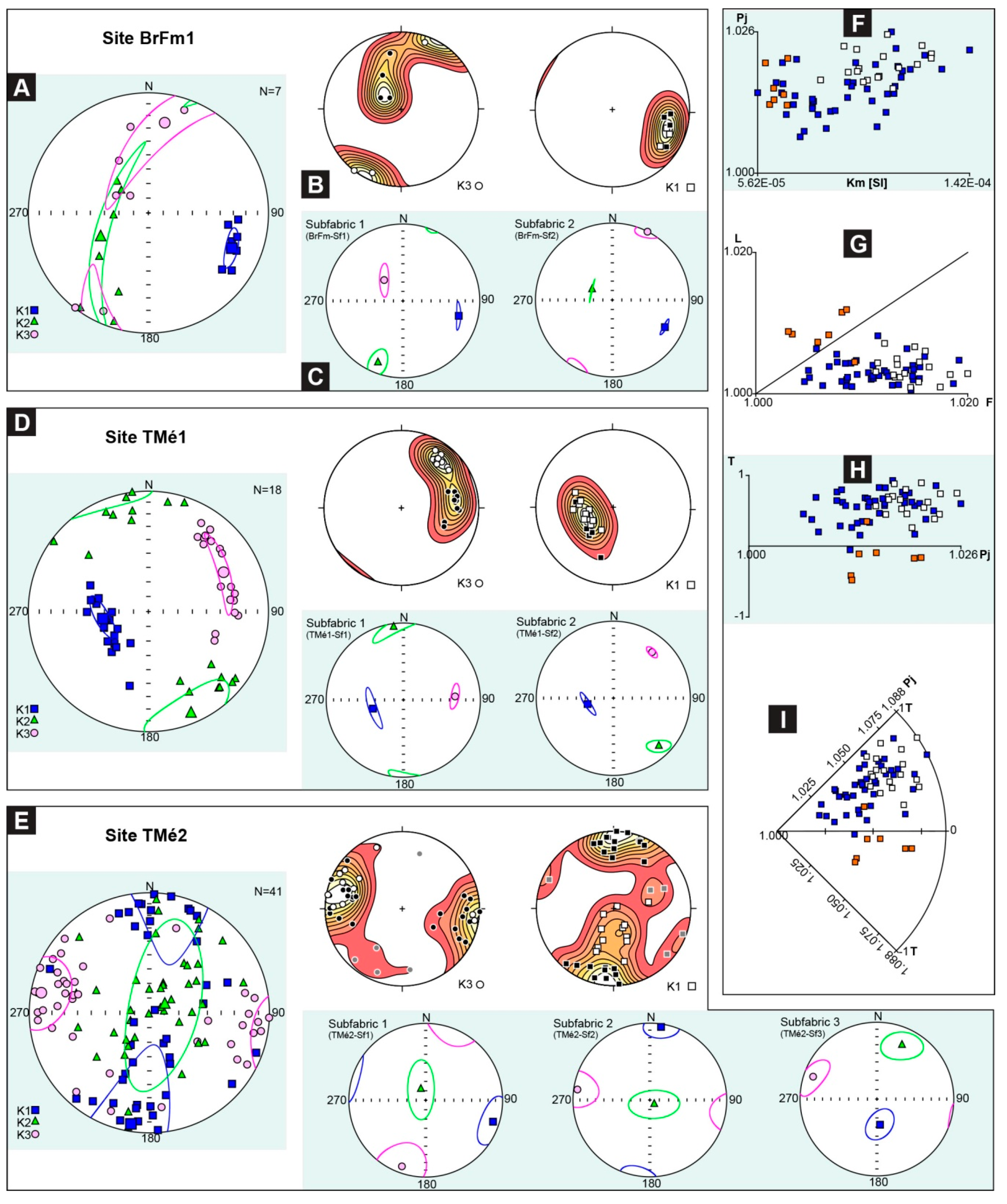
5.1. The Broken Formation

The analysis of the broken formation (Figure 5A) showed a prolate ellipsoid (k1>>k2 ≈ k3; −1 ≤ T < 0; L > F) (orange squares in Figure 5F–I) with a well-defined magnetic lineation east-southeast-striking. The k2 and k3 axes are inter-dispersed, showing a south-southwest- to northwest-striking distribution. The magnetic foliation is south-southwest-dipping and steeply inclined. Despite the limited data, two different subfabrics may be tentatively detected (Figure 5B,C):
  • A neutral subfabric (L ≈ F) showing a sub-horizontal magnetic foliation east-southeast-dipping and a cluster of k1 axes east-southeast-striking (subfabric1 in Figure 5C);
  • A prolate subfabric with a sub-vertical magnetic foliation and a cluster of k1 axes east-southeast–west-northwest-oriented (subfabric2 in Figure 5C).

5.2. The Tectonic Mélange

The Tectonic mélange was sampled in two sites, located at different distances from the regional northwest-striking thrust shear zone (TMé1 and TMé2; see Figure 2). Both sites showed oblate magnetic fabric (k1 ≈ k2 >> k3; 0 > T ≥ 1; F > L) with a strong magnetic foliation.
Site TMé1, which is located within the main shear zone (Figure 2), is characterized by a well-defined steeply-dipping magnetic lineation west-southwest-striking (Figure 5D), and sub-horizontal k2 axes, northwest-striking. The k1 and k2 axes distributions roughly defined the magnetic foliation plane which is west-southwest-dipping. Two coherent subfabrics show weakly different k3 and k2 orientations, ranging from east-west to northeast-southwest and from north-northwest–south-southeast to northwest-southeast, respectively.
SiteTMé2, which is located about 10 m away from the main shear zone (Figure 2), showed a complex blended fabric (see [103]), with a well-defined sub-vertical magnetic foliation around north-northeast-striking. This fabric consists of the combination of three different subfabrics, characterized by neutral to oblate ellipsoids (Figure 5E):
  • Subfabric 1 showed a sub-vertical magnetic foliation and a sub-horizontal k3 axis, east-southeast- and north-northeast-striking, respectively, while the magnetic lineation is east-southeast-striking;
  • Subfabric 2 displayed a north-northeast-striking sub-vertical magnetic foliation, sub-horizontal k1 and k3 axes north-northeast- and west-southwest-striking, respectively, and a sub-vertical k2 axis, which weakly deviated from the magnetic foliation;
  • Subfabric 3 showed a sub-vertical magnetic foliation, north-northeast-striking, and a k1 axis plunging at a high angle towards the south.

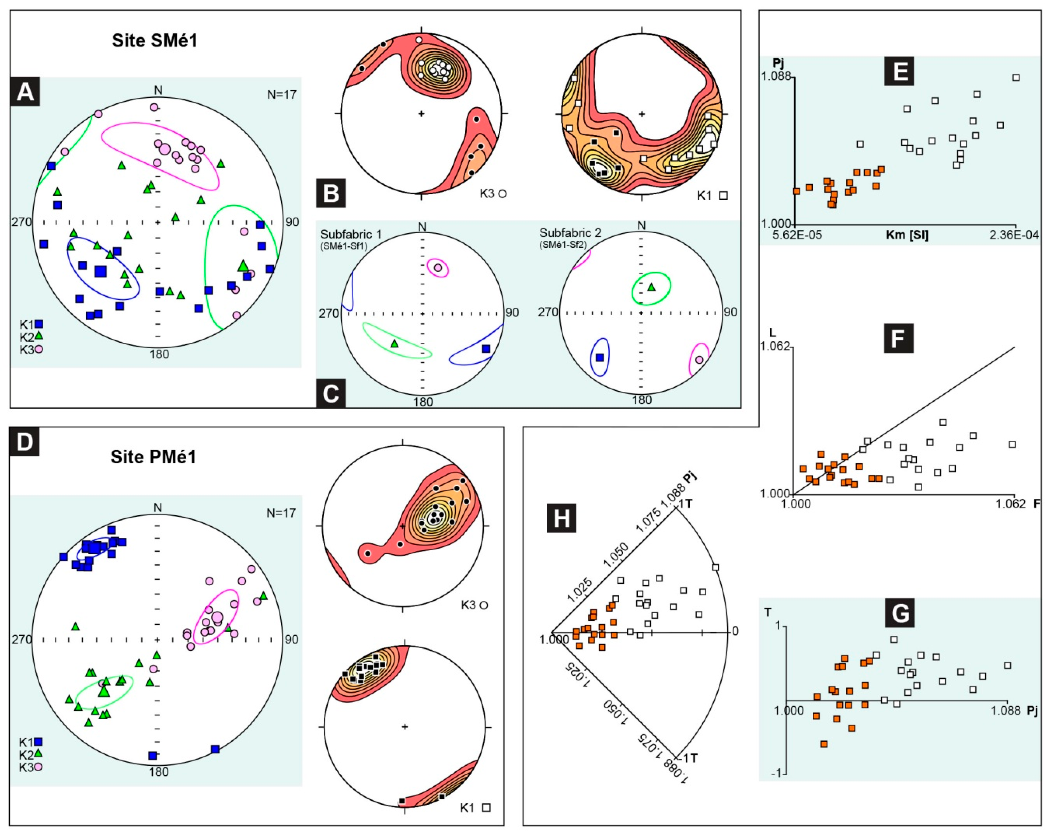
5.3. The Sedimentary Mélange

The magnetic fabric of the sedimentary mélange (SMé1, Figure 6A–C; see location in Figure 2) is characterized by a blended AMS fabric (see [103]), with a weakly dipping magnetic foliation and an oblate to neutral magnetic ellipsoid (white squares in Figure 6E–H). This fabric resulted from the combination of different samples collected within both the basal shear zone and the isotropic portion (i.e., some meters above the basal shear zone) of the sedimentary mélange, respectively (Figure 6B,C):
  • The basal shear zone (subfabric2 in Figure 6C) showed a neutral to oblate subfabric with the k1 axis southwest-striking, the k3 axis northwest-plunging at a low angle, and the k2 axis laying on the sub-vertical magnetic foliation, which is northeast-striking;
  • The isotropic portion (subfabric1 in Figure 6C) showed a oblate ellipsoid characterized by a well-defined magnetic foliation, southwest-dipping, containing statistically-distinct k1 and k2 axes, southeast- and southwest-striking, respectively.

5.4. The Polygenetic Mélange

The PMé1 (Figure 6D, see location in Figure 2) showed a cumulative magnetic fabric with a neutral ellipsoid (orange squares in Figure 6E–H) and no detectable subfabric combinations. The k3 axis is around east-northeast-striking, defining a magnetic foliation west-southwest-dipping with different angles. The slightly gathered k2 axes are southwest-plunging at variable angles, partially deviating from the magnetic foliation plane. The clustered k1 axes define a sub-horizontal magnetic lineation, northwest-striking.

6. Discussion: Correlation of the Magnetic Fabric with Mélange Forming Processes

The AMS analysis enabled the definition of specific configurations of the magnetic fabric (i.e., AMS ellipsoid and their axes orientation) for the different types of chaotic rock unit, reflecting the forming processes (i.e., tectonic, sedimentary, and their interlink and superposition) that were previously distinguished through structural field data.

6.1. The Broken Formation

The AMS fabric of the broken formation (site BrFm1 in Figure 2, see also Figure 5A–C) shows a prolate ellipsoid (BrFm1 in Figure 7) with a northwest-striking magnetic lineation (k1) aligned to the tectonic stretching direction. Distribution of k3 axes on a girdle pattern (Figure 5A) define a transitional- to-tectonic magnetic fabric, which is commonly associated with incipient deformation.
In fact, weak-to-incipient deformation induced the progressive deviation of k3 axes from a direction perpendicular to the bedding plane toward one parallel to the maximum tectonic shortening axis. In addition, the detected subfabrics (Figure 5B,C) suggest that the magnetic fabric resulted from the combination and superposition of two different deformational mechanisms and/or differently-oriented deformational events. The sub-horizontal east-southeast-dipping magnetic foliation of subfabric1 is subparallel to the southeast-dipping pseudo-bedding, and the magnetic lineation is aligned to the northwest-striking layer-parallel extension and related features (i.e., pinch-and-swell and boudinage) (BrFm-SF1 in Figure 7). These features are well-consistent with the combination of vertical compaction due to burial at the wedge front of the Ligurian accretionary complex. This occurred during the Late Cretaceous–early Eocene accretionary stage in wet and partially lithified sediments (e.g., [33,34,40,47,74]). On the contrary, the alignment of the northwest-striking magnetic lineation of subfabric2 (BrFm-SF2 in Figure 7) to the block long-axis lineation may represent the superposition of tectonic shearing, as sediment incorporated at the toe of the accretionary wedge (e.g., [34,80,111]). Thus, the broken formation magnetic fabric, is well comparable with the mesoscale structural fabric, showing a coeval development of flattened, intra-layer sheath-like folds, layer-parallel extensional fabric, and asymmetric boudinage likely resulting from the heterogeneity of deformation at the toe of the accretionary wedge.

6.2. The Tectonic Mélange

The magnetic fabric of the tectonic mélange, showing a slightly neutral to mainly oblate AMS ellipsoid with a sub-vertical magnetic foliation (TMé1 and TMé2 in Figure 7), revealed a transitional- to tectonic- magnetic fabric. Changes in magnetic lineation (k1) plunging angles and Pj values, approaching to the main regional-scale thrust surface (see Figure 5D–I), record the progressive deformation related to tectonic shearing onto the broken formation fabric.
In TMé1, located within the shear zone of the northwest-striking thrusts, the alignment of a steeply-dipping magnetic foliation to the mesoscale tectonic shear surfaces (i.e., R-shear, scaly fabric, shear surfaces; compare Figure 4C and Figure 5D), is well consistent with the development of tectonically-induced mesoscale shear deformation. The parallelism between the northeast-oriented magnetic lineation and the main tectonic shear direction (TMé1 in Figure 7) remarks the magnetic fabric formed during the late Oligocene–early Miocene out-of-sequence thrusting stage (see [33]).
On the contrary, the blended magnetic fabric of site TMé2, which is located away from the northwest-striking thrust and the related shear zone, represents the superposition of two tectonic subfabrics (subfabric2 and subfabric3) onto the subfabric1 (see Figure 5E). The latter is well-comparable with that of the broken formation (see subfabric2 of site BrFm1 in Figure 5C and Figure 7).
The configuration of subfabrics2 and 3, showing the reorientation of the k1 axes (Figure 5E), may represent two stages of progressive realignment of the ferromagnetic grains and clay particles of the broken formation during thrusting. In particular, subfabric2, which is characterized by a slightly neutral AMS ellipsoid with k1 axis south-southwest-plunging at a low angle (Figure 5E), represents a transitional fabric. This is consistent with the incipient deformation stage, showing convergence of long axes (k1) to the intersection between S and C planes. Instead, subfabric3, characterized by slightly oblate ellipsoid and k1 axes plunging at high angle toward the south (Figure 5E and Figure 7), may represent a clearly tectonic fabric possibly related to a subsequent stage of increasing deformation, with the progressive parallelization of the k1 axes to the shear direction.

6.3. The Sedimentary Mélange

The blended magnetic fabric (see [103]) of the sedimentary mélange (SMé1 in Figure 7), characterized by an oblate to neutral ellipsoid and an high dispersion of k1 and k2 axes, revealed the combination of different petrofabrics. The latter axes are consistent with the internal arrangement of viscous debris flows emplaced within wedge-top basins at the top of the Ligurian accretionary wedge in the late Oligocene–Early Miocene [18,33,83,87].
The well-flattened magnetic fabric of the upper isotropic portion of the sedimentary mélange (subfabric1 in Figure 6C) is clearly sedimentary. The relatively wide range of Pj is coherent with a random and disordered distribution of grains due to the gravity-driven depositional mechanism without any trace of shearing. The occurrence of distinct k1 and k2 axes clusters (Figure 6C) revealed partially-preferred orientations of para- and ferromagnetic grains induced by sedimentary (gravitational) processes of formation. Two different mechanisms could provide this magnetic fabric: (i) depositional processes under current flow associated with grain transport by traction, in which the cluster of k1 axes trends in the direction perpendicular to the flow [104], and (ii) a weak and non-pervasive deformation associated with the emplacement of overlaying debris flow (i.e., “cryptoslumps”, see also references [112,113]). On the contrary, subfabric2 showed a slightly neutral magnetic ellipsoid (Figure 6C,F–H) with southwest-striking k1 axes parallel to the orientation of the clast-long axis within the basal viscous shear zone of the sedimentary mélange (see [87]). The magnetic lineation (k1) is also consistent with the direction of extensional shearing. Thus, the AMS fabric reflects a significant preferred orientation of grains induced by the downslope emplacement of the sedimentary mélange as a cohesive debris flow (see, e.g., [21,23,25,87,114]).

6.4. The Polygenetic Mélange

The magnetic fabric of the polygenetic mélange (PMé1 in Figure 7) defined a neutral magnetic ellipsoid with a sub-horizontal magnetic foliation and well-clustered k1 axes. This pattern represents a transitional fabric due to the partially tectonic reorientation of the primary fabric of the sedimentary mélange (i.e., the MTD). In fact, the occurrence of some sub-vertical k3 axes associated with sub-horizontal k1 and k2 axes are well consistent with the remnant of a primary gravitationally-induced fabric, formed during the MTD emplacement. Instead, the girdle drawn by the k2 and k3 axes and the alignment of the k1 axes with the direction of S-C structures related to the northwest-verging out-of-sequence thrusting (i.e., late Oligocene–early Miocene thrusting stage, see [34]; compare Figure 4C and Figure 6B), clearly document the role played by tectonic processes in weakly reworking the primary fabric of the sedimentary mélange.

7. Concluding Remarks

The different types of chaotic rock unit (mélanges and broken formations), cropping out in different structural positions within the external Ligurian and Epiligurian units in the Northern Apennines (northwest Italy), represent the products of different interrelated and locally-superposed processes (sedimentary, tectonic, and polygenetic; see [33,56]), which accompanied the Late Cretaceous–early Miocene tectono-stratigraphic evolution of an exhumed Ligurian accretionary complex and the overlying wedge-top basin succession [33].
Through the analysis of the magnetic fabric of the different types of chaotic rock unit differing each other by diverse diagnostic block-in-matrix fabrics [33,56], our findings document that a close relationship exists between mesoscale structural fabrics and the configurations and orientation of the principal susceptibility axes of the magnetic fabric.
The broken formation shows a tectonic magnetic fabric with a prolate AMS ellipsoid. The magnetic lineation (k1) is consistent with the block-long axis and layer parallel extension directions, while the girdle-shaped distribution of k2 and k3 axes is well-consistent with a heterogeneous deformation, as occurred at the toe of the accretionary wedge (coeval flattening, boudinage, and layer-parallel extension; see [34]). The tectonic mélange showed a magnetic fabric with neutral-to-oblate AMS ellipsoids. The magnetic lineation and the magnetic foliation are parallel to the direction of shear and the mélange foliation, respectively. Away for the main thrust surface, the occurrence of an intermediate/transitional magnetic fabric documents the partial preservation of the primary broken formation fabric. The sedimentary mélange showed a depositional magnetic fabric defining an oblate AMS ellipsoid with a magnetic lineation perpendicular to the direction of emplacement. Only within the sheared horizon at the base of the gravitational body, the magnetic fabric defines a neutral ellipsoid with magnetic lineation parallel to the clast-long axis and the direction of downslope emplacement. The polygenetic mélange showed a transitional magnetic fabric with a neutral AMS ellipsoid. The magnetic lineation and the magnetic foliation are oriented perpendicular to the shear direction and parallel to the scaly fabric, respectively, while the girdle-shaped distribution of k2 and k3 axes is well-consistent with a partial reworking and reorientation of grains due to the overprinting of tectonic processes onto sedimentary ones.
Our findings thus document the significance of the application of the AMS method to the complex rock assemblages commonly characterizing subduction–accretionary complexes as a valuable tool in distinguishing different types of chaotic rock units (mélanges and broken formations). The comparison between field-observed meso-structural fabric and magnetic fabric on an exhumed subduction–accretion complex in the Northern Apennines allowed us to define and validate the diagnostic magnetic fabric features that are necessary to analytically distinguish the contribution of different mélange forming-processes (tectonic, sedimentary, and their mutual superposition) during its evolution. Importantly, since the studied Ligurian accretionary complex represents an ancient analogue for the shallow portion of present-day subduction complexes (e.g., [18,26,33,34,40]), the diagnostic magnetic fabric configuration defined for each type of chaotic rock unit may be successfully applied in the investigation of deformation in modern subduction–accretionary complexes where direct field-observations are not possible. Therefore, our results may provide potential significant constraints to better understand the internal structural architecture of modern subduction–accretion complexes, and the role played by different (and locally superposed) processes during their tectono-stratigraphic evolution.

Supplementary Materials

The following are available online at https://www.mdpi.com/2076-3263/9/9/381/s1.

Author Contributions

Conceptualization, A.F. and E.Z.; methodology, A.F., E.Z. and C.R.T.; validation, A.F., E.Z. and C.R.T.; formal analysis, A.F., G.C., C.R.T., E.S. and E.Z.; data curation, A.F., E.Z. and C.R.T.; writing—original draft preparation, A.F. and C.R.T.

Funding

The research has been supported by research grants from the Università di Torino (Ricerca Locale “ex 60%” 2014–2018) to A. Festa; from the Italian Ministry of Education, University and Research (“Finanziamentoannualeindividualedelleattività base di ricerca” 2017) to A. Festa; and (“Finanziamentoannualeindividualedelleattività base di ricerca” 2018) to E. Zanella.

Acknowledgments

We thank G.A.Pini, K. Ogata, and F. Remittifor their insightful discussion on various aspects of the evolution of the geology of the Ligurian accretionary complex, which were most helpful for the formulation of our ideas presented in this paper. We would like to express our sincere thanks to the two anonymous reviewers and S. Satolli for their constructive and thorough reviews, from which we have benefited greatly in revising our manuscript.

Conflicts of Interest

The authors declare no conflict of interest. The funders had no role in the design of the study; in the collection, analyses, or interpretation of data; in the writing of the manuscript, or in the decision to publish the results.

References

  1. Dilek, Y.; Festa, A.; Ogawa, Y.; Pini, G.A. Chaos and Geodynamics: Mélanges, Mélange-Forming Processes and Their Significance in the Geological Record. Tectonophysics 2012, 568–569, 1–6. [Google Scholar] [CrossRef]
  2. Festa, A.; Ogata, K.; Pini, G.A. Mélanges: 100th Anniversary of the Inception of the Term and Concept. Gondwana Res. 2019, 74, 1–6. [Google Scholar] [CrossRef]
  3. Karig, D.E.; Sharman, G.F. Subduction and Accretion in Trenches. GSA Bull. 1975, 86, 377–389. [Google Scholar] [CrossRef]
  4. Cloos, M. Flow Melanges: Numerical Modeling and Geologic Constraints on Their Origin in the Franciscan Subduction Complex, California. GSA Bull. 1982, 93, 330–345. [Google Scholar] [CrossRef]
  5. Moore, J.C.; Byrne, T. Thickening of Fault Zones: A Mechanism of Melange Formation in Accreting Sediments. Geology 1987, 15, 1040–1043. [Google Scholar] [CrossRef]
  6. Taira, A.; Hill, I.; Firth, J.; Berner, U.; Brückmann, W.; Byrne, T.; Chabernaud, T.; Fisher, A.; Foucher, J.-P.; Gamo, T.; et al. Sediment Deformation and Hydrogeology of the Nankai Trough Accretionary Prism: Synthesis of Shipboard Results of ODP Leg 131. Earth Planet. Sci. Lett. 1992, 109, 431–450. [Google Scholar] [CrossRef]
  7. Collot, J.-Y.; Ribodetti, A.; Agudelo, W.; Sage, F. The South Ecuador Subduction Channel: Evidence for a Dynamic Mega-Shear Zone from 2D Fine-Scale Seismic Reflection Imaging and Implications for Material Transfer. J. Geophys. Res. Solid Earth 2011, 116. [Google Scholar] [CrossRef]
  8. Fagereng, Å.; Remitti, F.; Sibson, R. Incrementally Developed Slickenfibers—Geological Record of Repeating Low Stress-Drop Seismic Events? Tectonophysics 2011, 510, 381–386. [Google Scholar] [CrossRef]
  9. Codegone, G.; Festa, A.; Dilek, Y. Formation of Taconic Mélanges and Broken Formations in the Hamburg Klippe, Central Appalachian Orogenic Belt, Eastern Pennsylvania. Tectonophysics 2012, 568–569, 215–229. [Google Scholar] [CrossRef]
  10. Mittempergher, S.; Cerchiari, A.; Remitti, F.; Festa, A. From Soft Sediment Deformation to Fluid Assisted Faulting in the Shallow Part of a Subduction Megathrust Analogue: The SestolaVidiciatico Tectonic Unit (Northern Apennines, Italy). Geol. Mag. 2018, 155, 438–450. [Google Scholar] [CrossRef]
  11. Lallemand, S.; Collot, J.-Y.; Pelletier, B.; Rangin, C.; Cadet, J.P. Impact of Oceanic Asperities on the Tectogenesis of Modern Convergent Margins. Oceanol. Acta 1990, 10, 17–30. [Google Scholar]
  12. Goldfinger, C.; Kulm, L.D.; McNeill, L.C.; Watts, P. Super-Scale Failure of the Southern Oregon Cascadia Margin. Pure Appl. Geophys. 2000, 157, 1189–1226. [Google Scholar] [CrossRef]
  13. von Huene, R.; Ranero, C.R.; Weinrebe, W.; Hinz, K. Quaternary Convergent Margin Tectonics of Costa Rica, Segmentation of the Cocos Plate, and Central American Volcanism. Tectonics 2000, 19, 314–334. [Google Scholar] [CrossRef]
  14. Collot, J.-Y.; Lewis, K.; Lamarche, G.; Lallemand, S. The Giant Ruatoria Debris Avalanche on the Northern Hikurangi Margin, New Zealand: Result of Oblique Seamount Subduction. J. Geophys. Res. Solid Earth 2001, 106, 19271–19297. [Google Scholar] [CrossRef]
  15. Sage, F.; Collot, J.-Y.; Ranero, C.R. Interplate Patchiness and Subduction-Erosion Mechanisms: Evidence from Depth-Migrated Seismic Images at the Central Ecuador Convergent Margin. Geology 2006, 34, 997–1000. [Google Scholar] [CrossRef]
  16. Ogawa, Y.; Anma, R.; Dilek, Y. Accretionary Prisms and Convergent Margin Tectonics in the Northwest Pacific Basin: Modern Approaches in Solid Earth Sciences; Springer: Dordrecht, The Netherlands, 2011; Volume 8, p. 277. [Google Scholar]
  17. Ogawa, Y. Conceptual Consideration and Outcrop Interpretation on Early Stage Deformation of Sand and Mud in Accretionary Prisms for Chaotic Deposit Formation. Gondwana Res. 2019, 74, 31–50. [Google Scholar] [CrossRef]
  18. Remitti, F.; Vannucchi, P.; Bettelli, G.; Fantoni, L.; Panini, F.; Vescovi, P. Tectonic and Sedimentary Evolution of the Frontal Part of an Ancient Subduction Complex at the Transition from Accretion to Erosion: The Case of the Ligurian Wedge of the Northern Apennines, Italy. GSA Bull. 2011, 123, 51–70. [Google Scholar] [CrossRef]
  19. Strasser, M.; Moore, G.F.; Kimura, G.; Kopf, A.J.; Underwood, M.B.; Guo, J.; Screaton, E.J. Slumping and Mass Transport Deposition in the Nankai Fore Arc: Evidence from IODP Drilling and 3-D Reflection Seismic Data. Geochem. Geophys. Geosyst. 2011, 12. [Google Scholar] [CrossRef]
  20. Kawamura, K.; Sasaki, T.; Kanamatsu, T.; Sakaguchi, A.; Ogawa, Y. Large Submarine Landslides in the Japan Trench: A New Scenario for Additional Tsunami Generation. Geophys. Res. Lett. 2012, 39. [Google Scholar] [CrossRef]
  21. Ogata, K.; Mountjoy, J.J.; Pini, G.A.; Festa, A.; Tinterri, R. Shear Zone Liquefaction in Mass Transport Deposit Emplacement: A Multi-Scale Integration of Seismic Reflection and Outcrop Data. Mar. Geol. 2014, 356, 50–64. [Google Scholar] [CrossRef]
  22. Ogata, K.; Festa, A.; Pini, G.A.; Pogačnik, Z.; Lucente, C.C. Substrate Deformation and Incorporation in Sedimentary mélanges (Olistostromes): Examples from the Northern Apennines (Italy) and NorthwesternDinarides (Slovenia). Gondwana Res. 2019, 74, 101–125. [Google Scholar] [CrossRef]
  23. Ogata, K.; Pogačnik, Ž.; Tunis, G.; Pini, G.A.; Festa, A.; Senger, K. A Geophysical-Geochemical Approach to the Study of the Paleogene Julian—Slovenian Basin “Megabeds” (Southern Alps—NorthwesternDinarides, Italy/Slovenia). Geosciences 2019, 9, 155. [Google Scholar] [CrossRef]
  24. Festa, A.; Dilek, Y.; Gawlick, H.-J.; Missoni, S. Mass-Transport Deposits, Olistostromes and Soft-Sediment Deformation in Modern and Ancient Continental Margins, and Associated Natural Hazards. Mar. Geol. 2014, 356, 1–4. [Google Scholar] [CrossRef]
  25. Festa, A.; Ogata, K.; Pini, G.A.; Dilek, Y.; Alonso, J.L. Origin and Significance of Olistostromes in the Evolution of Orogenic Belts: A Global Synthesis. Gondwana Res. 2016, 39, 180–203. [Google Scholar] [CrossRef]
  26. Festa, A.; Dilek, Y.; Mittempergher, S.; Ogata, K.; Pini, G.A.; Remitti, F. Does Subduction of Mass Transport Deposits (MTDs) Control Seismic Behavior of Shallow–Level Megathrusts at Convergent Margins? Gondwana Res. 2018, 60, 186–193. [Google Scholar] [CrossRef]
  27. Kawamura, K.; Ogawa, Y. Internal Structure, Active Tectonics and Dynamic Topography of the Eastern Nankai Accretionary Prism Toe, Japan, and Its Tsunamigenic Potential. Geol. Mag. 2018, 1–9. [Google Scholar] [CrossRef]
  28. Festa, A.; Cavagna, S.; Barbero, E.; Catanzariti, R.; Pini, G.A. Mid-Eocene giant slope failure (sedimentary mélanges) in the Ligurian accretionary wedge (NW Italy) and relationships with tectonics, global climate change and the dissociation of gas hydrates. J. Geol. Soc. 2019. [Google Scholar] [CrossRef]
  29. Brown, K.; Westbrook, G.K. Mud Diapirism and Subcretion in the Barbados Ridge Accretionary Complex: The Role of Fluids in Accretionary Processes. Tectonics 1988, 7, 613–640. [Google Scholar] [CrossRef]
  30. Moore, J.; Vrolijk, P. Fluids in Accretionary Prism. Rev. Geophys. 1992, 30, 113–135. [Google Scholar] [CrossRef]
  31. Kopf, A.J. Significance of Mud Volcanism. Rev. Geophys. 2002, 40, 2-1–2-52. [Google Scholar] [CrossRef]
  32. Camerlenghi, A.; Pini, G.A. Mud Volcanoes, Olistostromes and Argille Scagliose in the Mediterranean Region. Sedimentology 2009, 56, 319–365. [Google Scholar] [CrossRef]
  33. Codegone, G.; Festa, A.; Dilek, Y.; Pini, G.A. Small-Scale Polygenetic mélanges in the Ligurian Accretionary Complex, Northern Apennines, Italy, and the Role of Shale Diapirism in Superposed Mélange Evolution in Orogenic Belts. Tectonophysics 2012, 568–569, 170–184. [Google Scholar] [CrossRef]
  34. Festa, A.; Dilek, Y.; Codegone, G.; Cavagna, S.; Pini, G.A. Structural Anatomy of the Ligurian Accretionary Wedge (Monferrato, NW Italy), and Evolution of Superposed Mélanges. GSA Bull. 2013, 125, 1580–1598. [Google Scholar] [CrossRef]
  35. Moore, G.F.; Aung, L.T.; Fukuchi, R.; Sample, J.C.; Hellebrand, E.; Kopf, A.; Naing, W.; Than, W.M.; Tun, T.N. Tectonic, Diapiric and Sedimentary Chaotic Rocks of the Rakhine Coast, Western Myanmar. Gondwana Res. 2019, 74, 126–143. [Google Scholar] [CrossRef]
  36. Raymond, L.A. Classification of Melanges. In Geological Society of America Special Papers; Geological Society of America: Boulder, CO, USA, 1984; Volume 198, pp. 7–20. [Google Scholar]
  37. Raymond, L.A. Designating Tectonostratigraphic Terranes versus Mapping Rock Units in Subduction Complexes: Perspectives from the Franciscan Complex of California, USA. Int. Geol. Rev. 2015, 57, 801–823. [Google Scholar] [CrossRef]
  38. Raymond, L.A. Perspectives on the Roles of Melanges in Subduction Accretionary Complexes: A Review. Gondwana Res. 2019, 74, 68–89. [Google Scholar] [CrossRef]
  39. Cowan, D.S. Structural Styles in Mesozoic and Cenozoic Mélanges in the Western Cordillera of North America. GSA Bull. 1985, 96, 451–462. [Google Scholar] [CrossRef]
  40. Pini, G.A. Tectonosomes and Olistostromes in the Argille Scagliose of the Northern Apennines, Italy; Geological Society of America: Boulder, CO, USA, 1999; Volume 335. [Google Scholar]
  41. Osozawa, S.; Morimoto, J.; Flower, M. “Block-in-Matrix” Fabrics That Lack Shearing but Possess Composite Cleavage Planes: A Sedimentary Melange Origin for the Yuwan Accretionary Complex in the Ryukyu Island Arc, Japan. GSA Bull. 2009, 121, 1190–1203. [Google Scholar] [CrossRef]
  42. Wakabayashi, J. Anatomy of a Subduction Complex: Architecture of the Franciscan Complex, California, at Multiple Length and Time Scales. Int. Geol. Rev. 2015, 57, 1–78. [Google Scholar] [CrossRef]
  43. Tartarotti, P.; Festa, A.; Benciolini, L.; Balestro, G. Record of Jurassic mass transport processes through the orogenic cycle: Understanding chaotic rock units in the high-pressure Zermatt-Saas ophiolite (W-Alps). Lithosphere 2017, 9, 399–407. [Google Scholar] [CrossRef]
  44. Tartarotti, P.; Guerini, S.; Rotondo, F.; Festa, A.; Balestro, G.; Bebout, G.E.; Cannaò, E.; Epstein, G.S.; Scambelluri, M. Superposed sedimentary and tectonic block-in-matrix fabrics in a subductedserpentinite mélange (High-Pressure Zermatt Saas Ophiolite, Western Alps). Geosciences 2019, 9, 358. [Google Scholar] [CrossRef]
  45. Hsü, K.J. Principles of Mélanges and Their Bearing on the Franciscan-Knoxville Paradox. GSA Bull. 1968, 79, 1063–1074. [Google Scholar] [CrossRef]
  46. Lash, G.G. Diverse Melanges of an Ancient Subduction Complex. Geology 1987, 15, 652–655. [Google Scholar] [CrossRef]
  47. Bettelli, G.; Panini, F. I Mélanges Dell’Appennino Settentrionale Dal T. Tresinaro al T. Sillaro. Mem. Della Soc. Geol. Ital. 1987, 39, 187–214. [Google Scholar]
  48. Bettelli, G.; Bonazzi, U.; Panini, F. Schema introduttivo alla geologia delle Liguridi dell’Appennino Modenese e delle aree limitrofe. Mem. Della Soc. Geol. Ital. 1989, 39, 91–125. [Google Scholar]
  49. Bettelli, G.; Conti, S.; Panini, F.; Vannucchi, P.; Fioroni, C.; Fregni, P.; Bonacci, M.; Gibellini, R.; Mondani, C. The mapping of chaotic rocks in Abruzzo (Central Italy): Comparison with selected examples from Northern Apennines. In Mapping Geology in Italy; Pasquarè, G., Venturini, C., Groppelli, G., Eds.; APAT–SELCA: Firenze, Italy, 2004; pp. 199–206. [Google Scholar]
  50. Orange, D.L. Criteria Helpful in Recognizing Shear-Zone and Diapiric Mélanges: Examples from the Hoh Accretionary Complex, Olympic Peninsula, Washington. GSA Bull. 1990, 102, 935–951. [Google Scholar] [CrossRef]
  51. Alonso, J.L. Structure and Organization of the Porma Melange: Progressive Denudation of a Submarine Nappe Toe by Gravitational Collapse. Am. J. Sci. 2006, 306, 32–65. [Google Scholar] [CrossRef]
  52. Dela Pierre, F.; Festa, A.; Irace, A. Interaction of Tectonic, Sedimentary, and Diapiric Processes in the Origin of Chaotic Sediments: An Example from the Messinian of Torino Hill (Tertiary Piedmont Basin, Northwestern Italy). GSA Bull. 2007, 119, 1107–1119. [Google Scholar] [CrossRef]
  53. Yamamoto, Y.; Nidaira, M.; Ohta, Y.; Ogawa, Y. Formation of Chaotic Rock Units during Primary Accretion Processes: Examples from the Miura–Boso Accretionary Complex, Central Japan. Isl. Arc 2009, 18, 496–512. [Google Scholar] [CrossRef]
  54. Yamamoto, Y.; Tonogai, K.; Anma, R. Fabric-Based Criteria to Distinguish Tectonic from Sedimentary mélanges in the Shimanto Accretionary Complex, Yakushima Island, SW Japan. Tectonophysics 2011, 568. [Google Scholar] [CrossRef]
  55. Festa, A.; Pini, G.A.; Dilek, Y.; Codegone, G. Mélanges and Mélange-Forming Processes: A Historical Overview and New Concepts. Int. Geol. Rev. 2010, 52, 1040–1105. [Google Scholar] [CrossRef]
  56. Festa, A.; Pini, G.A.; Ogata, K.; Dilek, Y. Diagnostic Features and Field-Criteria in Recognition of Tectonic, Sedimentary and Diapiric Mélanges in Orogenic Belts and Exhumed Subduction-Accretion Complexes. Gondwana Res. 2019, 74, 7–30. [Google Scholar] [CrossRef]
  57. Vannucchi, P.; Bettelli, G. Myths and Recent Progress Regarding the Argille Scagliose, Northern Apennines, Italy. Int. Geol. Rev. 2010, 52, 1106–1137. [Google Scholar] [CrossRef]
  58. Festa, A. Tectonic, Sedimentary, and Diapiric Formation of the Messinian Mélange: Tertiary Piedmont Basin (Northwestern Italy). In Mélanges: Processes of Formation and Societal Significance; Wakabayashi, J., Dilek, Y., Eds.; Geological Society of America: Boulder, CO, USA, 2011; Volume 480, pp. 215–232. [Google Scholar]
  59. Wakabayashi, J. Mélanges of the Franciscan Complex, California: Diverse Structural Setting, Evidence for Sedimentary Mixing, and Their Connection to Subduction Processes. In Mélanges: Processes of Formation and Societal Significance; Wakabayashi, J., Dilek, Y., Eds.; Geological Society of America: Boulder, CO, USA, 2011; Volume 480, pp. 117–141. [Google Scholar]
  60. Wakabayashi, J. Sedimentary Compared to Tectonically-Deformed Serpentinites and Tectonic Serpentinite Mélanges at Outcrop to Petrographic Scales: Unambiguous and Disputed Examples from California. Gondwana Res. 2019, 74, 51–67. [Google Scholar] [CrossRef]
  61. Wakita, K. OPS Mélange: A New Term for Mélanges of Convergent Margins of the World. Int. Geol. Rev. 2015, 57, 529–539. [Google Scholar] [CrossRef]
  62. Fagereng, Å.; Sibson, R.H. Mélange Rheology and Seismic Style. Geology 2010, 38, 751–754. [Google Scholar] [CrossRef]
  63. Fagereng, Å.; Diener, J.F.A.; Ellis, S.; Remitti, F. Fluid-Related Deformation Processes at the up- and Downdip Limits of the Subduction Thrust Seismogenic Zone: What Do the Rocks Tell Us? In Geology and Tectonics of Subduction Zones: A Tribute to Gaku Kimura; Byrne, T., Underwood, M.B., III, Fisher, D., McNeill, L., Saffer, D., Ujiie, K., Yamaguchi, A., Eds.; Geological Society of America: Boulder, CO, USA, 2018; Volume 534. [Google Scholar]
  64. Bürgmann, R. The Geophysics, Geology and Mechanics of Slow Fault Slip. Earth Planet. Sci. Lett. 2018, 495, 112–134. [Google Scholar] [CrossRef]
  65. Boccaletti, M.; Coli, M.; Decandia, F.A.; Giannini, E.; Lazzarotto, A. Evoluzione dell’Appennino settentrionale secondo un nuovo modello strutturale. Mem. Della Soc. Geol. Ital. 1980, 21, 359–373. [Google Scholar]
  66. Dewey, J.F.; Helman, M.L.; Knott, S.D.; Turco, E.; Hutton, D.H.W. Kinematics of the Western Mediterranean. Geol. Soc. Lond. Spec. Publ. 1989, 45, 265–283. [Google Scholar] [CrossRef]
  67. Castellarin, A. Strutturazione eo-mesoalpina dell’Appennino Settentrionale attorno al nodo ligure. In Studi preliminari all’acquisizione dati del profilo CROP 1–1A La Spezia–Alpi orientali; Capozzi, R., Castellarin, A., Eds.; Studi Geol. Camerti; Università degli Studi di Camerino: Camerino, Italy, 1994; Volume 1992/2, pp. 99–108. [Google Scholar]
  68. Marroni, M.; Molli, G.; Montanini, A.; Tribuzio, R. The Association of Continental Crust Rocks with Ophiolites in the Northern Apennines (Italy): Implications for the Continent-Ocean Transition in the Western Tethys. Tectonophysics 1998, 292, 43–66. [Google Scholar] [CrossRef]
  69. Elter, P.; Grasso, M.; Parotto, M.; Vezzani, L. Structural Setting of the Apennine-Maghrebian Thrust Belt. Episodes 2003, 26, 205–211. [Google Scholar]
  70. Lucente, C.C.; Pini, G.A. Basin-Wide Mass-Wasting Complexes as Markers of the Oligo-Miocene Foredeep-Accretionary Wedge Evolution in the Northern Apennines, Italy. Basin Res. 2008, 20, 49–71. [Google Scholar] [CrossRef]
  71. Festa, A.; Pini, G.A.; Dilek, Y.; Codegone, G.; Vezzani, L.; Ghisetti, F.; Lucente, C.C.; Ogata, K. Peri-Adriatic Mélanges and Their Evolution in the Tethyan Realm. Int. Geol. Rev. 2010, 52, 369–403. [Google Scholar] [CrossRef]
  72. Festa, A.; Balestro, G.; Borghi, A.; De Caroli, S.; Succo, A. The Role of Structural Inheritance in Continental Break-up and Exhumation of Alpine Tethyan Mantle (Canavese Zone, Western Alps). Geosci. Front. 2019. [Google Scholar] [CrossRef]
  73. Barbero, E.; Festa, A.; Saccani, E.; Catanzariti, R.; D’Onofrio, R. Redefinition of the Ligurian Units at the Alps-Apennines Junction (NW Italy) and Their Role in the Evolution of the Ligurian Accretionary Wedge: Constraints from Mélanges and Broken Formations. J. Geol. Soc. 2019. [Google Scholar] [CrossRef]
  74. Bettelli, G.; Vannucchi, P. Structural Style of the Offscraped Ligurian Oceanic Sequences of the Northern Apennines: New Hypothesis Concerning the Development of Mélange Block-in-Matrix Fabric. J. Struct. Geol. 2003, 25, 371–388. [Google Scholar] [CrossRef]
  75. CerrinaFeroni, A.; Ottria, G.; Ellero, A. The northern Apennine, Italy: Geological structure and transpressive evolution. In Geology of Italy; Crescenti, U., d’Offizi, S., Merlino, S., Sacchi, L., Eds.; Special Volume for the IGC 32; Geological Society of Italy: Florence, Italy, 2004; pp. 15–32. [Google Scholar]
  76. Marroni, M.; Meneghini, F.; Pandolfi, L. Anatomy of the Ligure-Piemontese Subduction System: Evidence from Late Cretaceous–Middle Eocene Convergent Margin Deposits in the Northern Apennines, Italy. Int. Geol. Rev. 2010, 52, 1160–1192. [Google Scholar] [CrossRef]
  77. Festa, A.; Codegone, G. Geological Map of the External Ligurian Units in Western Monferrato (Tertiary Piedmont Basin, NW Italy). J. Maps 2013, 9, 84–97. [Google Scholar] [CrossRef]
  78. Barbero, E.; Festa, A.; Fioraso, G.; Catanzariti, R. Geology of the Curone and Staffora Valleys (NW Italy): Field Constraints for the Late Cretaceous—Pliocene Tectono-Stratigraphic Evolution of Northern Apennines. J. Maps 2017, 13, 879–891. [Google Scholar] [CrossRef]
  79. Bettelli, G.; Bonazzi, U.; Fazzini, P.; Gasperi, G.; Gelmini, R.; Panini, F. Nota illustrativa alla Carta geologica dell’Appennino modenese e delle aree limitrofe. Mem. Della Soc. Geol. Ital. 1989, 39, 487–498. [Google Scholar]
  80. Bettelli, G.; Bonazzi, U.; Fazzini, P.; Panini, F. Schema introduttivo alla geologia delle Epiliguridi dell’Appennino modenese e delle aree limitrofe. Mem. Della Soc. Geol. Ital. 1989, 39, 215–244. [Google Scholar]
  81. Mutti, E.; Papani, L.; Di Biase, D.; Davoli, G.; Mora, S.; Segadelli, S.; Tinterri, R. Il Bacino Terziario Epimesoalpino e Le Sue Implicazioni Sui Rapporti Tra Alpi Ed Appennino. Mem. Di Sci. Geol. Di Padova 1995, 47, 217–244. [Google Scholar]
  82. Panini, F.; Fioroni, C.; Fregni, P.; Bonacci, M. Le Rocce Caotiche Dell’Oltrepo Pavese: Note Illustrative Della Carta Geologica Dell’Appennino Vogherese Tra Borgo Priolo e Ruino. Atti Ticinensi Di Sci. Della Terra 2002, 43, 83–109. [Google Scholar]
  83. Panini, F.; Fioroni, C.; Fregni, P. Le Brecce Argillose Di Musigliano (Appennino Vogherese–Tortonese): Dati Stratigrafici Preliminari. Rend. Online Della Soc. Geol. Ital. 2013, 26, 21–31. [Google Scholar]
  84. Pini, G.; Lucente, C.; Cowan, D.; De Libero, C.; Dellisanti, F.; Landuzzi, A.; Negri, A.; Tateo, F.; Del Castello, M.M.M.; Cantelli, L. The Role of Olistostromes and Argille Scagliose in the Structural Evolution of the Nothern Apennines. In Field Trip Guidebooks, Proceedings of the 32nd IGC, Florence, Italy, 20–28 August 2004; Memorie Descrittive della Carta Geologica d’Italia 63; Guerrieri, L., Rischia, I., Serva, L., Eds.; APAT: Roma, Italy, 2004; B13; pp. 1–40. [Google Scholar]
  85. Ogata, K.; Tinterri, R.; Pini, G.A.; Mutti, E. The Specchio Unit (Northern Apennines, Italy): An Ancient Mass Transport Complex Originated from Near-Coastal Areas in an Intra-Slope Setting. In Submarine Mass Movements and Their Consequences; Yamada, Y., Kawamura, K., Ikehara, K., Ogawa, Y., Urgeles, R., Mosher, D., Chaytor, J., Strasser, M., Eds.; Advances in Natural and Technological Hazards Research; Springer: Dordrecht, The Netherlands, 2012; pp. 595–605. [Google Scholar]
  86. Festa, A.; Fioraso, G.; Bissacca, E.; Petrizzo, M.R. Geology of the Villalvernia—Varzi Line Between Scrivia and Curone Valleys (NW Italy). J. Maps 2015, 11, 39–55. [Google Scholar] [CrossRef]
  87. Festa, A.; Ogata, K.; Pini, G.A.; Dilek, Y.; Codegone, G. Late Oligocene–Early Miocene Olistostromes (Sedimentary mélanges) as Tectono-Stratigraphic Constraints to the Geodynamic Evolution of the Exhumed Ligurian Accretionary Complex (Northern Apennines, NW Italy). Int. Geol. Rev. 2015, 57, 540–562. [Google Scholar] [CrossRef]
  88. Balestro, G.; Festa, A.; Dilek, Y.; Tartarotti, P. Pre-Alpine Extensional Tectonics of a Peridotite-Localized Oceanic Core Complex in the Late Jurassic, High-Pressure Monviso Ophiolite (Western Alps). Episodes 2015, 38, 266–282. [Google Scholar] [CrossRef]
  89. Boccaletti, M.; Coli, M. Carta strutturale dell’Appennino settentrionale. In Progetto Finalizzato Geodinamica, Sottoprogetto 5; Cnrpubblicazione 429. S.El.Ca. Scale 1:250,000 3 Sheets; CNR: Firenze, Italy, 1982. [Google Scholar]
  90. Kusky, T.M.; Bradley, D.C. Kinematic Analysis of Mélange Fabrics: Examples and Applications from the McHugh Complex, Kenai Peninsula, Alaska. J. Struct. Geol. 1999, 21, 1773–1796. [Google Scholar] [CrossRef]
  91. Naylor, M.A.; Mandl, G.; Supesteijn, C.H.K. Fault Geometry in Basement-Induced Wrench Faulting under Different Initial Stress States. J. Struct. Geol. 1986, 8, 737–752. [Google Scholar] [CrossRef]
  92. Pini, G.A.; Ogata, K.; Camerlenghi, A.; Festa, A.; Lucente, C.C.; Codegone, G. Sedimentary mélanges and Fossil Mass-Transport Complexes: A Key for Better Understanding Submarine Mass Movements? In Submarine Mass Movements and Their Consequences; Yamada, Y., Kawamura, K., Ikehara, K., Ogawa, Y., Urgeles, R., Mosher, D., Chaytor, J., Strasser, M., Eds.; Advances in Natural and Technological Hazards Research; Springer: Dordrecht, The Netherlands, 2012; pp. 585–594. [Google Scholar]
  93. Middleton, G.V.; Hampton, M.A. Part I. Sediment Gravity Flows: Mechanics of Flow and Deposition. In Turbidites and Deep-Water Sedimentation: Lecture Notes for a Short Course; Middleton, G.V., Bouma, A.H., Eds.; Society of Economic Paleontologists and Mineralogists, Pacific Section: Tulsa, OK, USA, 1973; pp. 1–88. [Google Scholar]
  94. Lowe, D.R. Sediment Gravity Flows; II, Depositional Models with Special Reference to the Deposits of High-Density Turbidity Currents. J. Sediment. Res. 1982, 52, 279–297. [Google Scholar]
  95. Mulder, T.; Alexander, J. The Physical Character of Subaqueous Sedimentary Density Flows and Their Deposits. Sedimentology 2001, 48, 269–299. [Google Scholar] [CrossRef]
  96. Jelinek, V. The Statistical Theory of Measuring Anisotropy of Magnetic Susceptibility of Rocks and its Application; Geofyzika Brno.: Ječná, Czech Republic, 1977. [Google Scholar]
  97. Chadima, M.; Jelínek, V. Anisoft 4.2—Anisotropy Data Browser. Contrib. Geophys. Geod. 2008, 38, 41. [Google Scholar]
  98. Tarling, D.H.; Hrouda, F. The Magnetic Anisotropy of Rocks; Chapman and Hall: London, UK, 1993. [Google Scholar]
  99. Maxbauer, D.P.; Feinberg, J.M.; Fox, D.L. MAX UnMix: A Web Application for Unmixing Magnetic Coercivity Distributions. Comput. Geosci. 2016, 95, 140–145. [Google Scholar] [CrossRef]
  100. Hrouda, F. The Use of the Anisotropy of Magnetic Remanence in the Resolution of the Anisotropy of Magnetic Susceptibility into Its Ferromagnetic and Paramagnetic Components. Tectonophysics 2002, 347, 269–281. [Google Scholar] [CrossRef]
  101. Borradaile, G.J.; Jackson, M. Structural Geology, Petrofabrics and Magnetic Fabrics (AMS, AARM, AIRM). J. Struct. Geol. 2010, 32, 1519–1551. [Google Scholar] [CrossRef]
  102. Jelinek, V. Characterization of the Magnetic Fabric of Rocks. Tectonophysics 1981, 79, T63–T67. [Google Scholar] [CrossRef]
  103. Borradaile, G.; Jackson, M. Anisotropy of Magnetic Susceptibility (AMS): Magnetic Petrofabrics of Deformed Rocks. Geol. Soc. Lond. Spec. Publ. 2004, 238, 299–360. [Google Scholar] [CrossRef]
  104. Sagnotti, L. Magnetic Anisotropy. In Encyclopedia of Solid Earth Geophysics; Gupta, H.K., Ed.; Springer: Dordrecht, The Netherlands, 2011; pp. 717–729. [Google Scholar]
  105. Weil, A.B.; Yonkee, A. Anisotropy of Magnetic Susceptibility in Weakly Deformed Red Beds from the Wyoming Salient, Sevier Thrust Belt: Relations to Layer-Parallel Shortening and Orogenic CurvatureAnisotropy of Magnetic Susceptibility in Weakly Deformed Red Beds. Lithosphere 2009, 1, 235–256. [Google Scholar] [CrossRef]
  106. Tokiwa, T.; Yamamoto, Y. Relationship between Magnetic Fabrics and Shear Direcrtions in Mélange within the Miyama Formation Shimanto Accretionary Complex, Japan. Tectonophysics 2012, 568–569, 53–64. [Google Scholar] [CrossRef]
  107. Sagnotti, L.; Faccenna, C.; Funiciello, R.; Mattei, M. Magnetic Fabric and Structural Setting of Plio-Pleistocene Clayey Units in an Extensional Regime: The Tyrrhenian Margin of Central Italy. J. Struct. Geol. 1994, 16, 1243–1257. [Google Scholar] [CrossRef]
  108. Plenier, G.; Camps, P.; Henry, B.; Ildefonse, B. Determination of Flow Directions by Combining AMS and Thin-Section Analyses: Implications for Oligocene Volcanism in the Kerguelen Archipelago (Southern Indian Ocean). Geophys. J. Int. 2005, 160, 63–78. [Google Scholar] [CrossRef]
  109. Aubourg, C.; Smith, B.; Eshraghi, A.; Lacombe, O.; Authemayou, C.; Amrouch, K.; Bellier, O.; Mouthereau, F. New Magnetic Fabric Data and Their Comparison with Palaeostress Markers in the Western Fars Arc (Zagros, Iran): Tectonic Implications. Geol. Soc. Lond. Spec. Publ. 2010, 330, 97–120. [Google Scholar] [CrossRef]
  110. Caricchi, C.; Cifelli, F.; Kissel, C.; Sagnotti, L.; Mattei, M. Distinct Magnetic Fabric in Weakly Deformed Sediments from Extensional Basins and Fold-and-Thrust Structures in the Northern Apennine Orogenic Belt (Italy). Tectonics 2016, 35, 238–256. [Google Scholar] [CrossRef]
  111. Kimura, G.; Mukai, A. Underplated Units in an Accretionary Complex: Melange of the Shimanto Belt of Eastern Shikoku, Southwest Japan. Tectonics 1991, 10, 31–50. [Google Scholar] [CrossRef]
  112. Cronin, M.; Tauxe, L.; Constable, C.; Selkin, P.; Pick, T. Noise in the Quiet Zone. Earth Planet. Sci. Lett. 2001, 190, 13–30. [Google Scholar] [CrossRef]
  113. Schwehr, K.; Tauxe, L. Characterization of Soft-Sediment Deformation: Detection of Cryptoslumps Using Magnetic Methods. Geology 2003, 31, 203–206. [Google Scholar] [CrossRef]
  114. Kuranaga, M.; Kawamura, K.; Kanamatsu, T. The Progressive Development of Microfabrics from Initial Deposition to Slump Deformation: An Example from a Modern Sedimenary Mélange on the Nankai Prism. J. Geol. Soc. 2019. [Google Scholar] [CrossRef]
Figure 2. Simplified geological-structural map of the Voghera sector of the Northern Apennines (modified from [33,87]) (A) with location of the anisotropy of magnetic susceptibility (AMS) samples. (B) Schematic column (not to scale) showing the vertical piling of the different mélange and broken formation units and locations of AMS samples.
Geosciences 09 00381 g002
Figure 3. Close up view of the different hand-sample-to-meso-scale block-in-matrix fabrics of mélanges and broken formations studied. Broken formation (i.e., the Argille varicolori of the External Ligurian units): (A) asymmetrical brittle boudinage and pinch-and-swell structures of alternating varicolored shaly, clayey, and marly layers; (B) disharmonic-to-isoclinal and transposed folds with sub-horizontal axial surfaces aligned parallel to the tectonic layering and/or pseudo-bedding, which results in the development of pinch-and-swell structures and boudinage of shaly layers due to layer-parallel extension along the fold limbs. Tectonic mélange: (C) polished cut of the high-strain shear zone that shows millimeter-sized elongated asymmetric “exotic” clasts in a fine grained matrix. In the central part of the photograph, elongated clasts show a P-C fabric; (D) shear transposition and overprinting of the previously formed isoclinal folds of the broken formation that forms isolated fold hinges with axial surfaces aligned to planar northeast-verging shear zones and mesoscale thrust faults, resulting in the production of the tectonic mélange. Sedimentary mélange: (E) polished surface of hand sample showing the isotropic texture of the brecciated shaly matrix with irregular shaped blocks randomly distributed within the matrix; (F) polished surface of hand sample of the basal shear zone of the sedimentary mélange, showing the reorientation of elongated hard clasts to S-C fabric. Polygenetic mélange: (GH) sub-angular to angular, and tabular clasts and blocks, centimeter- to decimeter in size, embedded in a brecciated shaly matrix, and gently reoriented by a scaly fabric related to tectonic deformation.
Geosciences 09 00381 g003
Figure 4. Diagrams showing block characteristics and rock fabric in different types of mélanges: (A) aspect ratio (block long axis/short axis) vs block long axis; (B) aspect ratio vs. location of chaotic units (i.e., distance from the thrust faults). Data are plotted as means with 95% error bars indicated; (C) mesoscale data (Schmidt net, lower hemisphere) of scaly fabric, lineation of the long axis of the blocks, and folds of broken formation, tectonic mélange, and polygenetic mélange.
Geosciences 09 00381 g004
Figure 5. Tectonic fabric of tectonic mélange specimens: (A) stereoplots (lower-hemisphere projections) showing the shapes and attitudes of the magnetic susceptibility ellipsoids from the broken formation (site BrFm1); (B) density diagrams of k1 and k3 axes (contour interval = 10) and (C) relative subfabrics; tectonic mélanges, site TMé1 (D) and Site TMé2 (E), AMS data. Whole diagrams for the measured tectonic fabric in which orange, white, and blue squares are respectively BrFm1, TMé1, and TMé2 data: (F) anisotropy degree vs mean susceptibility; (G) magnetic lineation vs. magnetic foliation; (H) shape parameter vs. corrected anisotropy degree; (I) π/4 segment polar plot (see [103]), in which Pj represents the radius and T the arc length.
Geosciences 09 00381 g005
Figure 6. Magnetic fabric of sedimentary (SMé1) and polygenetic (PMé1) mélange specimens: (A) stereoplots (lower-hemisphere projections) showing the shapes and attitudes of the magnetic susceptibility ellipsoids from site SMé1; (B) density diagrams of k1 and k3axes (contour interval = 10) and (C) relative subfabrics; (D) and site PMé1 AMS data. Whole diagrams for the measured sedimentary fabric in which white and orange are, respectively, SMé1 and PMé2 data: (E) anisotropy degree vs. mean susceptibility; (F) magnetic lineation vs magnetic foliation; (G) shape parameter vs corrected anisotropy degree;(H) π/4 segment polar plot (see [103]), in which Pj represents the radius and T the arc length.
Geosciences 09 00381 g006
Figure 7. (A) Conceptual cross-section (not to scale) of the Ligurian accretionary complex (modified from [87]), the blue box represents the schematic 3D stratigraphic column of Figure 7B; (B) conceptual 3D stratigraphic column (not to scale) showing the internal arrangement and structural position of the different types of mélange (tectonic, sedimentary, and polygenetic) and broken formation and related AMS ellipsoids oriented to present-day geographic coordinates (see text for explanation). Red and black lines in the 3D stratigraphic column represent tectonic and stratigraphic contacts, respectively.
Geosciences 09 00381 g007
Table 1. Magnetic susceptibility and AMS data from broken formation (BrFm1), tectonic (TMé1 and TMé2), sedimentary (SMé1), and polygenetic (PMé1) mélanges and relative subfabrics (Sf1, Sf 2, Sf 3). n/N = number of specimens used for calculation/number of measured specimens (n/N* = data not sufficient to calculate accurate confidence ellipse); Km = mean susceptibility; L = magnetic lineation; F = magnetic foliation; T = shape parameter; Pj = corrected anisotropy degree; ± σ = standard deviation of each parameter; magnetic lineation: D, I = declination/inclination of the k1 axis with angles of the 95% confidence ellipse (E1-2, E1-3), respectively; magnetic foliation pole: D, I = declination/inclination of the k3 axis with angles of the 95% confidence ellipse (E3-2, E3-1), respectively.
Siten/NKm
(±σ)
L
(±σ)
F
(±σ)
T
(±σ)
Pj
(±σ)
Magnetic LineationMagnetic Foliation
(µSI)k1/k2k2/k3 DIE1-2E1-3DIE1-2E1-3
(°)(°)(°)(°)(°)(°)(°)(°)
BrFm17/7641.0111.001−0.8201.0131132612.04.8102571.010.7
(±4)(±0.003)(±0.003)(±0.269)(±0.004)
Sf 14/7*651.0071.005−0.2161.01210526--31860--
(±3)(±0.002)(±0.003)(±0.351)(±0.001)
Sf 23/7*641.0111.007−0.1861.01811724--271--
(±4)(±0.002)(±0.001)(±0.038)(±0.003)
TMé118/201061.0051.0110.3511.0162615916.64.9633025.74.5
(±13)(±0.002)(±0.002)(±0.173)(±0.003)
Sf 19/201101.0041.0150.5971.0202545622.14.5863312.44.6
(±17)(±0.002)(±0.003)(±0.199)(±0.003)
Sf 29/201021.0031.0140.6641.0182586214.03.040236.24.1
(±6)(±0.001)(±0.001)(±0.152)(±0.001)
TMé241/42931.0011.0070.7461.009189762.318.9281924.419.1
(±21)(±0.002)(±0.004)(±0.217)(±0.004)
Sf 15/42781.0031.0070.4141.010108720.817.2199931.719.5
(±19)(±0.001)(±0.004)(±0.165)(±0.005)
Sf 224/42901.0041.0070.2821.0119416.313.3279627.114.1
(±20)(±0.002)(±0.004)(±0.245)(±0.004)
Sf 312/421051.0031.0100.5571.0131736218.412.82891320.112.2
(±17)(±0.001)(±0.003)(±0.165)(±0.004)
SMé117/241801.0131.0150.0591.0282294025.813.864139.614.0
(±32)(±0.007)(±0.011)(±0.233)(±0.015)
Sf 111/241701.0071.0340.6391.0441191236.310.2194010.68.5
(±33)(±0.006)(±0.008)(±0.244)(±0.009)
Sf 26/241991.0201.0350.2641.0572232620.98.4129815.79.6
(±22)(±0.004)(±0.015)(±0.160)(±0.018)
PMè117/18961.0101.009−0.0771.0193261210.36.1694821.88.8
(±19)(±0.004)(±0.006)(±0.340)(±0.006)

