
A Review of Recent Developments in Autotuning Methods for Fractional-Order Controllers
by
 , , , and
Cristina I. Muresan
1 ,
,
Isabela Birs
1,2,3,* ,
,
Clara Ionescu
1,2,3 ,
,
Eva H. Dulf
1 and
Robin De Keyser
2,3 1
Automation Department, Technical University of Cluj-Napoca, 400114 Cluj-Napoca, Romania
2
DySC Research Group on Dynamical Systems and Control, Faculty of Engineering and Architecture, Ghent University, Tech Lane Science Park 125, B-9052 Ghent, Belgium
3
EEDT Decision & Control, Flanders Make Consortium, Tech Lane Science Park 131, B-9052 Ghent, Belgium
*
Author to whom correspondence should be addressed.
Fractal Fract. 2022, 6(1), 37; https://doi.org/10.3390/fractalfract6010037
Submission received: 13 December 2021
/
Revised: 28 December 2021
/
Accepted: 5 January 2022
/
Published: 11 January 2022
(This article belongs to the Special Issue Fractional-Order System: Control Theory and Applications)
Abstract
:The scientific community has recently seen a fast-growing number of publications tackling the topic of fractional-order controllers in general, with a focus on the fractional order PID. Several versions of this controller have been proposed, including different tuning methods and implementation possibilities. Quite a few recent papers discuss the practical use of such controllers. However, the industrial acceptance of these controllers is still far from being reached. Autotuning methods for such fractional order PIDs could possibly make them more appealing to industrial applications, as well. In this paper, the current autotuning methods for fractional order PIDs are reviewed. The focus is on the most recent findings. A comparison between several autotuning approaches is considered for various types of processes. Numerical examples are given to highlight the practicality of the methods that could be extended to simple industrial processes.
1. Introduction
Despite the abundance of research in advanced control strategies, the PID (proportional-integrative-derivative) controller remains the preferred control algorithm in industrial applications [1,2]. To produce the desired effects, PIDs need to be adequately tuned. A mathematical model is usually needed in order to properly tune the controller. However, large industrial plants are characterized by numerous sub-systems and obtaining an accurate process model is not cost effective as it can be difficult and/or time consuming. To overcome this issue, two different approaches for autotuning PIDs were developed, as indicated in Figure 1.
Both approaches use step or sinusoidal input data and collect the process output response. For a direct autotuner the PID parameters are determined directly from process input/output data, while for the indirect PID autotuner, simple process models are first determined and then the PID parameters are computed according to some tuning rules based on the model parameters. The majority of indirect methods use either first-order plus dead time (FOPDT) or second-order plus dead time (SOPDT) models.
Two of the most popular autotuning methods have been developed by Ziegler and Nichols [3]. One of these methods is a direct approach, based on the relay experiment, as indicated in Figure 2. Once the relay test is performed on a process, it will lead to a sinusoidal output signal which is used to estimate the process critical frequency and the corresponding critical gain. Tuning rules based on the process critical frequency and gain are employed to compute the PID controller parameters. The Ziegler-Nichols direct autotuning method is highly popular because of its simplicity and good performance results.
Several extensions of this approach and alternative solutions have been developed over the years. One of these uses the describing function analysis and a simple relay feedback test to estimate the process critical gain and corresponding frequency [4]. A solution for noisy signals was proposed based on a relay with hysteresis [5]. An artificial time delay is added within the relay closed-loop system in order to determine the process gain and phase at a random oscillation frequency. Then, a PI (proportional-integrative) controller is tuned according to this process data. A modified Ziegler-Nichols method [6]—where the ratio between the integral and derivative time constants is r = 4—was also developed. Other research papers discuss the impact the ratio value has upon the control performance [7]. Solutions to improve the robustness of the control system have been addressed [2]. Åström and Hägglund [1] use the relay test to design controllers based on robust loop shaping, with a clear tradeoff between robustness and performance.
The second method developed by Ziegler and Nichols [3] consists in applying a step signal on the process input and collecting the output data. The method is suitable for processes that have FOPDT dynamics or exhibit an S-shaped response, as indicated in Figure 3. The approach goes through an indirect step, where the parameters of the FOPDT model are estimated. Finally, the PID controller parameters are computed using a set of tuning rules that depend on the FOPDT model parameters.
The demand for better control performance and increased robustness has led to several modifications of the standard PID controller, including a generalization to fractional order [8]. Research on fractional order PID (FO-PID) controllers has demonstrated that this generalization allows for more flexibility in the design, due to the two supplementary tuning parameters involved, the fractional orders of integration and differentiation [9,10,11,12,13]. This flexibility comes with important advantages, such as better closed-loop performance, disturbance rejection capabilities, improved control of time-delay systems and increased robustness [9,10,11,12,13,14]. The fractional order PID transfer function is given as:
where and are the fractional orders of integration and differentiation, respectively, and kp is the proportional gain, and Ti and Td are the integral and derivative time constants. The “classical” tuning rules used to determine the five controller parameters are derived from the following performance specifications [9,12,15,16,17]:
- 1.
- A gain crossover frequency ωc. This leads to the magnitude condition:with Hol(s) the open-loop transfer function is defined as: Hol(s) = P(s). CFO-PID(s), where P(s) is the process transfer function;
- 2.
- A phase margin PM. This leads to the phase condition:
- 3.
- Iso-damping property (or robustness to gain variations). This is specified through:where denotes the frequency. This last condition ensures that the overshoot of the closed-loop system remains approximately constant in the case of gain variations;
- 4.
- Good output disturbance rejection. This leads to a constraint on the sensitivity function S:for frequencies , with B a scalar;
- 5.
- High frequency noise rejection. This leads to a constraint on the complementary sensitivity function T as:for frequencies , with A a scalar.
Further information regarding the tuning, implementation and related topics to fractional order PIDs can be found in some excellent review papers [15,16,18,19,20,21,22,23,24]. The phase shaper [25] is among the first automatic controller designs that uses fractional calculus tools. The autotuning method is based on the iso-damping property, but the final controller is an integer order PID. Throughout the past two decades, a couple of FO-PID autotuning methods have emerged. Some of these provide direct and indirect tuning rules for FO-PIDs in general or for fractional order PI (FO-PI) controllers. The purpose of this manuscript is to offer a comprehensive review of these autotuning methods, to compare them and to discuss which method is ranked best for controlling a specific type of process.
The paper is structured as follows. Section 2 and Section 3 provide for a review of the most widely known indirect and direct autotuning methods for FO-PIDs, while Section 4 provides for some numerical examples. Possible applications of autotuning methods are reviewed in Section 5, along with a survey on self-tuning FO-PIDs. The last section concludes the paper.
2. Indirect Fractional Order Autotuning Methods
A popular indirect autotuning method, suitable only for FO-PIs, was developed by extending the Ms constrained integral (MIGO)-based controller design approach [26]. F-MIGO tuning determines the optimum parameters of the FO-PI controller such that the load disturbance rejection is optimized, with a constraint on the maximum or peak sensitivity. The F-MIGO method provides the tuning rules for the FO-PI controller provided that the process step response has an S-shaped form, as indicated in Figure 3, that could be approximated by the following transfer function:
where k is the process gain, L is the delay and T is the time constant of the process. The relative dead time can be computed as:
Systems where L >> T are delay dominant, whereas systems in which T >> L are lag dominant. Research studies performed in [26] revealed that the FO-PI fractional order is almost independent of L, but depends on the relative dead time. For some particular situations, where , an integer order PI controller was determined to be more suitable for controlling the process. A summary of the results is indicated below:
The proportional and integrative gains of the FO-PI controller were also determined as a function of the relative dead time:
An indirect autotuning method that applies to the S-shaped step response process was developed in [27]. The tuning is unnecessarily complicated as the parameters of (7) are firstly estimated and then used to determine the process critical frequency and critical gain , according to:
Then, the parameters of an integer order PID are determined using the previously computed process critical frequency and gain, as well as three additional design parameters referring to the ratio of the integral and derivative time constants, loop phase and gain:
where , rb and are design parameters [28]. Once the PID controller parameters are computed, a possible range for the fractional orders in the FO-PID is selected and an optimization routine is performed. The algorithm attempts to minimize the integral time absolute error with the open loop gain and phase margin imposed as design specifications.
Another indirect tuning method is proposed in [29] for processes that produce an S-shaped step response. The method is based on determining first the process dead time L and time constant T, as well as the value at which the system reaches steady state k. The standard Ziegler-Nichols equations are used then to estimate the kp, Ti and Td parameters of an integer order PID. Then, the fractional orders of differentiation and integration are determined by the Nelder-Mead optimization algorithm in order to meet certain phase and gain margins. A second approach based on the standard Cohen-Coon method is also used in [29], for processes that exhibit first order plus dead time dynamics. Based on the process parameters, the integer order PID parameters are first computed. The Nelder-Mead optimization algorithm is used afterwards to estimate the fractional orders of differentiation and integration based on certain phase and gain margin requirements. The Cohen-Coon tuning method is proposed as an alternative to the Ziegler-Nichols approach in order to improve the slow, steady state response of the latter.
An indirect autotuning method for designing only FO-PI controllers using the Ziegler-Nichols open-loop approach is described in [30]. The parameters of the integer order PI controller are firstly determined using the standard Ziegler-Nichols approach. In order to improve the overall closed-loop response, the research suggests that the PI performance can be improved a lot with a fractional order of integration. An error filter as proposed in [31] is used for steady state error compensation:
where n is chosen to be small enough so that high frequency specifications are maintained and the system gain will not be altered drastically. The research in [30] proposed a modification of (13) such that the value of n is adjustable with respect to the fractional order of integration. The tuning of the fractional order and of the filter is performed by trial and error for a specific type of process. The method is evaluated experimentally on a steam temperature process and compared to the F-MIGO method [26] in terms of robustness for set point changes and disturbance rejection. The proposed controller shows better performance compared to the F-MIGO autotuning method, but it also requires higher control effort.
In [32], two existing analytical methods for tuning the parameters of fractional PIDs are reviewed. Then, for two specific sets of performance criteria similar to (2)–(6), the corresponding sets of tuning rules are developed based on an optimization method applied to the FO-PID control of an S-shaped process dynamics similar to (7). The newly developed tuning rules for fractional order PIDs use the time delay value and the estimated process time constant, T, much like the standard S-shaped Ziegler-Nichols approach, to produce the controller parameters. The method works provided the step response of the process is S-shaped. These two methods were initially presented in [33]. The first set of rules developed works if and , while the second set of rules can be applied for processes with and . Both sets of rules are determined in a similar manner. For a batch of process described as FOPDT systems, a set of performance specifications is imposed. The set included values for the gain crossover frequency, for the phase margin, a high-frequency value for the improved high-frequency noise cancellation and the corresponding maximum magnitude limit, as well as a low frequency value for improved output disturbance and the corresponding maximum magnitude. Tuning by minimization is then applied using the fmincon Matlab® (Natick, Massachusetts, USA) function, where the magnitude equation in (2) is used as the main function to minimize, whereas the remaining conditions in (3)–(6) are used as constraints. Using least squares fit, polynomials are determined to compute the controller parameters based on the process time constant T and time delay L: . Using Figure 4 and Figure 5, for the first set of rules and for the second one, the FO-PID controller parameters, as indicated in (1), can be finally computed:
3. Direct Fractional Order Autotuning Methods
Most of the direct autotuning methods are based on using the relay test to determine the process critical gain and critical period of oscillations, but other methods have been developed [34].
Several generalizations of the Ziegler-Nichols ultimate gain method have been proposed over the years for the tuning of FO-PIDs. A new tuning method for such a controller that combines both the Ziegler-Nichols as well as the Astrom and Hagglund methods has been proposed in [35]. The idea is based on obtaining the process critical frequency and critical gain and then computing the kp and Ti parameters using the classical Ziegler-Nichols method. For a specified phase margin, the Td parameter is computed using the Astrom and Hagglund method. Two equations referring to the controller’s real and imaginary parts are obtained. Fine tuning of Td is employed to achieve the best numerical solution of the equations, for each specified phase margin. Matlab®’s built in functions, such as fsolve, are used to solve the two equations to obtain numerical values of λ and μ by considering the new value of Td for each specified phase margin. An optimization Simulink model is used to obtain a better step response. The least squares method is used in the optimization model and the optimized FO-PID parameters are obtained. The approach is tedious and involves three controller designs before the final optimized FO-PID is obtained. However, the design allows for a direct specification of the loop phase margin.
In [36], an extension of the modified Ziegler-Nichols tuning rules for fractional-order controllers is presented. The proposed design approach is only suitable for tuning fractional order PI controllers. The tuning rules are derived without any knowledge of the process model, but they require the critical frequency , as well as the corresponding critical gain kcr. Based on this process information, the FO-PI autotuning objective is to determine the controller parameters such that the loop frequency response is moved to a point in the Nyquist plane where a performance criterion is minimized, according to a constraint. The performance criterion is mathematically expressed as a measure of the system ability to handle low-frequency load disturbances, subjected to a robustness constraint referring to the maximum sensitivity function of the closed-loop system. The tuning rules are given by:
where , , , and , with k the process gain as indicated in (7).
The method is compared with several other direct and indirect autotuning methods for integer order PIDs and it provides good performance results. The method is also compared to some similar autotuning approaches developed in [37,38] and the results demonstrate the superiority of the current approach.
A similar idea as the one used in [31] is employed in [39], where an error filter is cascaded with a FO-PI controller. Unlike the autotuning approach taken in [31], the research in [39] is focused on estimating the parameters of an integer order PI controller using the relay method. An estimation of the process critical gain and period of oscillation is firstly determined, which in turn leads to the computation of an integer order PI controller parameters according to the standard Ziegler-Nichols approach. The same error filter is used in [39] as in [31] with the same advantage. Various values for the fractional order integration are used and the results evaluated on a steam temperature process. Experimental results show that the FO-PI controller leads to better performance during the set-point change and load disturbance test in terms of output and control effort. However, poor closed-loop performance is obtained if λ is set too low. Even though both the direct [39] and the indirect [31] autotuning methods are simple enough for designing the FO-PI controllers, there is no clear advice on the selection of the fractional order of integration.
A modification of the Ziegler-Nichols closed-loop method is proposed in [40]. The method provides for an improvement of the standard Ziegler-Nichols results. The idea is based on the fact that a fractional order can help shape the “direction” of the loop frequency response in a fixed point in the Nyquist plot and thus keep the loop frequency response further away from the −1 point. The process critical frequency of oscillation, as well as the critical gain are obtained based on the relay test. To simplify the tuning method, the same fractional order of integration and differentiation is used in the FO-PID, similarly to [41]:
where and . The ratio between the integral and derivative time constants is considered to be a design parameter. The final tuning rules are exemplified for a ratio r = 4, similarly to [6,41]. Unlike the standard Ziegler-Nichols approach, the tuning rules depend not only on the process critical gain Kcr and critical period of oscillation Pcr, but also on the fractional order. The parameters of the FO-PID controller can thus be easily computed, without any complex optimization procedure [40], as indicated in Table 1.
The critical process gain and period of oscillation are used in [42] to determine the parameters of a FO-PID controller. Three sets of tuning rules are developed. Processes described as FOPDT systems are used for two of the sets, whereas for the third one, integrative processes are considered. The first set of tuning rules applies when the critical period of oscillations and . For the case when , a second set of tuning rules is developed. Both of these are quite restrictive and do not often work properly for plants with a pole at the origin [42]. The third set of rules is designed specifically for integrative processes (without time delay), but can be used only when and . The research in [42] concludes that the closed-loop performance can be poor near the borders of the mentioned range. All of these rules were developed in order to meet certain performance specifications regarding the loop gain crossover frequency, phase margin, iso-damping, rejection of high-frequency noise and output disturbance. All tuning rules are developed similarly to those in [32], by minimizing the magnitude equation in (2) and using the remaining conditions in (3)–(6) as design constraints. The controller parameters are obtained by polynomial fitting using least squares. The coefficients of the polynomials for the three sets of tuning rules are indicated in Figure 6, Figure 7 and Figure 8.
The relay test is also used in [43], but with a variation that includes also a time delay, as indicated in Figure 9. The process frequency response at any frequency can be identified using this scheme. The main issue is to determine the correct value of the time delay that corresponds to a specific frequency. An iterative method is used [44] and two initial values for the time delay and their corresponding frequencies are needed to start the iteration.
The autotuning method is based on specifying an iso-damping property, a gain crossover frequency and a phase margin. A fractional order PI controller is designed first, followed by a fractional order PD controller with a filter. The fractional order PI controller will be used to ensure the iso-damping property around the gain crossover frequency wcg. The slope of the phase of the plant is computed using the gain crossover frequency and the corresponding phase and a supplementary frequency and its corresponding process phase as resulting from the relay experiment. Once the slope is cancelled using the FO-PI controller, the FO-PD controller is designed to fulfill the design specifications of gain crossover frequency and phase margin. To ensure a maximum robustness to plant gain variations, a robustness criterion based on the flatness of the phase curve of the FO-PD controller is used such that the resulting phase of the open-loop system will be the flattest possible. The procedure is rather lengthy. A mechanical unit consisting mainly of a servo motor is used to experimentally validate the proposed method. The experimental results illustrate the effectiveness of this method.
The same method is described in [45], where experimental results with the FO-PID on a similar servo motor are used to validate the efficiency of the approach. A refinement of the relay feedback test in [43,45] is introduced in [46]. The improvement is based on adding a moving average filter. Simulation results for the control of a position servo with time delay are presented and validate the autotuning algorithm. The same autotuning method for determining a FO-PID controller for the servo system in [46] is presented in [47]. A similar approach is detailed in [48] for the design of FO-PID controllers. Two numerical case studies are provided for a double-integrator process and a fractional order integrative process. The simulation results validate the autotuning method.
Instead of using the relay test to determine the process magnitude, phase and phase slope, a single sine test at the gain crossover frequency is used in [34]. Novel filtering techniques are used to determine the process phase slope, as indicated in Figure 10. To determine the parameters of either a FO-PI or a FO-PD controller, performance specifications regarding the phase margin, gain crossover frequency and iso-damping property are used. The process magnitude, phase and phase slope previously determined are used in the resulting nonlinear equations. Optimization techniques or graphical methods are then employed to determine the controller parameters. Numerical examples are used to validate the approach. A different approach is presented in [49], where a forbidden region circle is defined based on the iso-damping property and phase margin specifications. The same sine test used in [34] is required here as well, in order to estimate the process phase, magnitude and phase slope. Instead of using optimization routines, the parameters of the optimal fractional order PID controller are determined by minimizing the slope difference between the circle border and the loop-frequency response. Numerical results are presented to validate the approach.
4. Numerical Examples
Some of the previously presented autotuning methods are used to determine the parameters of various types of fractional-order controllers for a series of processes that exhibit time delays, integrative effects, overdamped and poorly damped responses, higher orders. For simplicity, only the most recent and widely used autotuning methods are considered. All resulting fractional-order controllers are implemented using the same method and the same approximation parameters [50]. For the numerical examples considered in this manuscript, all fractional-order controllers are implemented with the proportional, fractional integration and differentiation actions on the error signal. The peaks in some FO-PID controller output signals are not the result of the tuning; they are simply the result of using derivative action on a setpoint step. These can be removed by implementing the FO-PI action on the error signal and FO-D action on the output signal.
4.1. The FOPDT Lag-Dominant Process
The following FOPDT lag-dominant process taken from [26] is considered:
In this case, k = 2.4315, L = 1.0787, T = 12.5688. Based on the relay test, the critical gain is Kcr = 7.78 and Pcr = 4.175. The parameters of the fractional-order controllers used for comparative purposes are indicated in Table 2. Indirect [26,27,32] and direct tuning methods [36,40,42,49] are used. The direct autotuning method in [34] produces the same result as in [49] and, therefore, was omitted from the comparison. Only the first set of tuning rules in [32] is used, as the second set of tuning rules cannot be applied. The same is valid for the direct autotuning method in [42], where only the first set of tuning rules is used, since the other two sets of tuning rules cannot be applied to this particular process.
The FO-PID [42] leads to a highly oscillating closed-loop response, while the FO-PID [32] is an unstable controller, which suggests that the proposed tuning rules work poorly for the lag-dominant system in (17). In fact, in both cases the expected phase margin is 38° [32,42], which explains the highly oscillating character. The FO-PI [49] was tuned to meet the iso-damping property, as well as a gain crossover frequency of 0.2 rad/s and a phase margin of 70°. These performance specifications were selected in order to obtain a small overshoot, as well as the fastest possible settling time. The closed-loop results considering step reference tracking and disturbance rejection are given in Figure 11, while the numerical values of the overshoot, settling time and disturbance rejection time are given in Table 3. The results show that the smallest overshoot is obtained using the FO-PI in [49], at the expense of a large settling time and the time required to reject the load disturbance. Small overshoot is obtained also using the FO-PID of Tepljakov in [27] or using the F-MIGO method [26], while the settling time is slightly larger in the latter case. However, the required control effort for Tepljakov’s FO-PID [27] is extremely large compared to the other methods, as indicated in Figure 11b). A larger control effort is also observed in the case of the FO-PI controller in [40], which achieves the fastest settling time and the smallest disturbance rejection time. A decent control effort is necessary when using FO-PI controllers tuned according to [26,36,49]. Among these, the fastest settling time is obtained with the FO-PI controller [26], while the smallest overshoot is achieved by the FO-PI controller [49]. Improved settling time might be possible in this last case, if a FO-PD controller is designed and implemented in series with the FO-PI.
4.2. The Higher Order Process
The following higher order process taken from [36] is considered:
In this case, k = 1, L = 1.42, T = 2.92 and the critical gain is Kcr = 4 and Pcr = 6.28 [36]. The parameters of the fractional-order controllers used for comparative purposes are indicated in Table 4. Indirect [26,32] and direct tuning methods [36,40,42,49] are used. The direct autotuning method in [34] produces the same result as in [49] and therefore was omitted from the comparison. Only the first set of tuning rules in [32] is used, as the second set of tuning rules cannot be applied. The same is valid for the direct autotuning method in [42], where only the first set of tuning rules is used, since the other two sets of tuning rules cannot be applied to this particular processes.
Figure 12 shows the closed-loop results obtained with the first three controllers in Table 4, while Figure 13 presents the closed-loop simulations obtained with the last three controllers. Note that the FO-PI [49] controller was first tuned for a gain crossover frequency of 0.5 rad/s and a phase margin of 38°. This is in agreement to the performance specifications used in [32,42] for the first set of tuning rules. The results in Figure 13 show that indeed similar overshoot and settling times are obtained with the fractional-order controllers tuned according to [32,42,49].
Table 5 contains the performance evaluation of the fractional-order controllers from Figure 12. The remaining three controllers in Figure 13 are not evaluated due to the large overshoot and settling time. The direct autotuning method from [49] can be used to tune a better FO-PI controller. Table 4 shows the resulting parameters of this improved FO-PI controller, which was tuned to meet a gain crossover frequency of 0.2 rad/s and a phase margin of 75°. The performance of this better FO-PI controller is compared to that of the FO-PI controller in [36], which achieves the best overshoot and settling time. The comparative simulation results are given in Figure 14 and in Table 5.
To estimate the quantitative results given in Table 5 for the FO-PI and FO-PID controllers designed according to [26,40], the closed-loop simulation results from Figure 12 were considered. The quantitative results in Table 5 show that the smallest overshoot is possible using the FO-PI controller tuned using the methods in [36,49], which are also suitable to achieve a quick disturbance rejection. Similarly to the lag-dominant case study, in this case as well, the FO-PID controller [40] achieves the smallest settling time and the fastest disturbance rejection time, at the expense of an increased control effort similar to that of the FO-PID [42] and larger compared to the other controllers.
4.3. The Integrating Time-Delay Process
An integrating time-delay process [46] is considered here. The transfer function is:
The classical Ziegler-Nichols autotuning method has a major disadvantage: poor results are obtained regarding setpoint tracking, especially when used with integrating systems [1]. Several extensions and improvements have been developed over the years to deal with such systems. The autotuning methods based on an S-shaped response of the process cannot be used in this particular situation.
In [47], an iterative experiment of a relay with delay is applied to the process in order to determine the process magnitude, phase and phase slope at a specific gain crossover frequency 2.3 rad/s. Then, a FO-PI in series with a FO-PD controller are designed to meet the iso-damping property, a gain crossover frequency of 2.3 rad/s for the open-loop system and a phase margin of 72°. The resulting fractional-order controller is given by [47]:
Four other direct autotuning methods are used for comparison purposes. First, based on the relay test, the critical gain is Kcr = 36.88 and Pcr = 1.1043. The parameters of the fractional-order controllers used for comparative purposes are indicated in Table 6, where the fractional-order controllers have been determined using [40,42,49]. The first and the third set of tuning rules in [42] are used to estimate the FO-PID controller parameters, as the second set cannot be applied for the process in (19). The tuning rules in [42] were developed for integrative processes without time delays (third set) and for FOPDT processes (first and second set). For the process in (19), the third set of tuning rules [42] leads to an unstable controller. Figure 15 shows the simulation results. The quantitative performance results are indicated in Table 7. Similar overshoot is obtained for the fractional-order controller in (20) designed using [47] and for the FO-PI controller [49], despite the latter having a large settling time. The fastest FO-PID controller is yet again the one designed according to [40]. The poorest overshoot along with a significant settling time is obtained with the FO-PID [42]. A comparison of the required control effort based on Figure 15b,c shows the increased amplitudes of the input signals are necessary for the FO-PIDs designed based on [40,42,47]. The smallest control effort is required by the FO-PI controller tuned according to [49], which also exhibits the largest settling time and a significant disturbance rejection time. However, this controller is also the simplest one, without any derivative effect.
4.4. The FOPDT Delay-Dominant Process
A FOPDT delay-dominant process is considered in the comparison, with the transfer function given by:
In this case, k = 1, L = 0.4, T = 0.2 and the critical gain is Kcr = 1.5202 and Pcr = 1.0985. Three indirect autotuning methods are used in the comparisons with the FO-PID controllers computed according to [32] using the first and the second set of rules for S-shaped process response. The third method is the F-MIGO method described in [26]. The resulting controller parameters are indicated in Table 8. Five direct autotuning methods are also used for the comparison, namely: FO-PID tuned according to the first and second set of rules in [42], FO-PID computed based on the method in [40] and two FO-PI controllers determined using [36,49]. The controller parameters for these cases are also given in Table 8. The FO-PI [49] is tuned to meet the iso-damping property, a gain crossover frequency 1.2 rad/s and a 70° phase margin. The closed-loop results are indicated in Figure 16 and Figure 17, while the performance is evaluated using quantitative measures as indicated in Table 9. The FO-PID controller obtained using the second set of tuning rules in [42] is not included in the comparison, due to its highly oscillating nature.
A small overshoot is obtained with the FO-PI controllers [26,36,49], combined with small settling times and fast disturbance rejection. The control effort in all these cases is similar, according to Figure 16b. FO-PID tuned using [40] manages to achieve a small settling time for this case study, as well. Good results are also obtained for disturbance rejection, at the expense of a larger control effort, compared to the other controllers (Figure 17b). FO-PIDs determined according to [32,42] lead to larger overshoots and increased settling times, as well as a poorer disturbance rejection, as indicated in Figure 17a. The required control effort for these controllers is small (Figure 17b), comparable to the input amplitudes given in Figure 16b.
4.5. The Poorly Damped Process
A final case study is considered in this section, with the process described by the following transfer function:
The indirect autotuning methods based on an S-shaped response cannot be applied for (21). An FO-PI controller tuned according to [36] is compared with a FO-PID obtained using the method in [40] and a FO-PI controller determined using [49]. First, the relay method is used to estimate the critical gain as Kcr = 0.0709 and Pcr = 2.8. These critical gain and period of oscillations allow the design of a FO-PID controller according to the first set of tuning rules in [42]. However, the proportional gain obtained in this way is negative and destabilizes the closed-loop system. Thus, the design is not included in this comparison. To tune the FO-PI controller [49], a sine test is firstly applied to the process to determine its phase, magnitude and phase slope. Then, the parameters of the FO-PI controller are determined such that the open-loop system achieves a gain crossover frequency of 0.09 rad/s and a phase margin of 75°, along with the iso-damping property. The parameters of the fractional-order controllers are given in Table 10. Figure 18 shows the closed-loop results, as well as the required input signals. The performance measures are indicated in Table 11. The simulation results in Figure 18 and Table 11 show that the fastest settling time is achieved by the FO-PID controller [40], with a zero overshoot. However, in this case, the required control effort is the largest. The two FO-PI controllers determined using [36,49] have a similar overshoot, as well as control effort. For the latter, the settling and the disturbance rejection times are larger.
For second-order poorly damped processes, most fractional order autotuning methods cannot be applied, except for [47,49]. The direct autotuning method in [47] leads to a FO-PI in series with a FO-PD controller, of the form given in (20), whereas the method in [49] produces a simpler FO-PI controller. Similarly to the results in Table 7, a faster settling time and better disturbance rejection are achieved using the fractional-order controller in [47], due to the FO-PD component.
4.6. Remarks on Comparative Simulation Results
The simulations results and closed-loop performance analysis shows that some of these autotuning methods allow for greater flexibility in the design, such as [34,47,49]. A faster settling time is obtained in all case studies using the autotuning method in [40]. The drawback consists in a larger control effort. The simple tuning rules from [32,42] are generally outperformed by the other autotuning methods reviewed, except for delay dominant systems, where the performance is close to the best one. For higher order systems and poorly damped ones, the best closed-loop results are obtained using the autotuning methods in [36,49] for both reference tracking and disturbance rejection. For FOPDT delay-dominant processes, the results show that the parameters of the fractional-order controllers should be estimated using the autotuning methods in [26,36,49]. In this case, improved reference tracking and disturbance rejection are obtained. For integrating time-delay processes, the best results in terms of overshoot are obtained using either a FO-PID determined based on the autotuning method in [47] or in [49]. The best settling time is obtained using either the autotuning method in [40,47]. However, the FO-PID controller autotuned according to [47] requires a significant control effort, larger than those in [40,49]. For FOPDT lag-dominant processes, the autotuning methods from [26,27,49] ensure a small overshoot, whereas fast settling and disturbance rejection times are achieved using FO-PIDs determined according to [26,27,40]. However, the control effort required when using the FO-PIDs tuned based on [27,40] is larger compared to the FO-PID tuned using the approach in [26].
5. Applications and Self-Tuned FO-PIDs
Autotuning methods have been used to produce fractional-order controllers for different processes. The purpose of this section is to provide some applicative examples of autotuning methods for fractional-order controllers designed mostly according to the methods presented in Section 2 and Section 3. The autotuning method in [34] is applied to a multivariable time-delay process to tune the FO-PI controllers for each loop [51]. The method in [49] is applied for designing fractional-order controller for a multivariable refrigeration system using vapor compression [52], a heterogeneous dynamic system [53] and to a highly coupled multivariable system [54]. A robust autotuning method is described and implemented for controlling an aerodynamic system in [55]. An experimental validation of the direct autotuning method in [49] is provided in [55] for controlling an UR10 robot. The autotuning method in [34] is applied to tune a FO-PD controller for vibration suppression in a smart beam [56]. An autotuning method designed for poorly damped systems that shapes the closed-loop system in order to achieve better damping is proposed in [57]. The design is performed in the frequency domain and requires information regarding the process magnitude and phase for five frequencies. Experimental results are given to validate the efficiency of the method.
A “plug and play” solution for a multivariable FO-PI controller is developed in [58] for controlling a multivariable twin-rotor aerodynamical system. A decentralized approach is considered and three performance specifications, as in (2)–(4), are used to compute the parameters of the two FO-PI controllers, one for azimuth and one for pitch angle control. The design is based on a novel, simplified algorithm using vector theory, where the proportional and integral terms are defined as vectors. The vectorial representation of the FO-PI controller as the sum of z1 and z2 is indicated in Figure 19.
Then, using classical trigonometric equations based on Figure 1, the proportional gain and integral time constant of the FO-PI controller are determined as a function of the fractional order , using the gain crossover equation (2) and the phase margin equation in (3). The procedure is iterative and computes the kp and Ti parameters for small increments of . Then, the iso-damping property in (4) is evaluated and is selected to be the value that minimizes (4). Finally, kp and Ti are computed using the selected value of The fractional-order controller is implemented in a self-tuning structure as indicated in Figure 20, where the “Controller designer” block includes the iterative procedure. The “System identifier” block is used to estimate the process parameters online which are then used in the iterative procedure to determine the new values for the FO-PI controller. A recursive simple least squares algorithm is implemented in the “System identifier” block.
Experimental results are provided to demonstrate the efficiency of the autotuning method. A step reference change of −1 rad for the azimuth angle and a step change of 0.2 rad for the pitch angle is considered, with the experimental results provided in Figure 21, demonstrating that reference tracking can be achieved successfully using the proposed multivariable self-tuned FO-PI control strategy.
An autotuning approach for FO-PIDs is used to control the air-conditioning fan coil unit [59]. A basic differential evolution algorithm is modified by varying the mutation factor and crossover rate and used to tune the five parameters of indoor temperature FO- PID controller. Numerical simulations are presented that show that the approach is reliable and the related control performance indexes meet the requirements of comfortable air-conditioning design and control criteria.
Improvements in FO-PID controller design have been considered in order to determine algorithms that perform a better tuning in real time. One solution to this issue is the self-tuned FO-PID controller. The purpose of this last part of the manuscript is to present some ideas regarding additional solutions to autotuning methods that could facilitate the industrial acceptance of FO-PID controllers. In what follows, the manuscript covers an important part of adaptive control algorithms, namely, self-tuning methods, applied to fractional-order controllers. Only the most recent findings in this area of research are reviewed.
Fuzzy logic is usually used to achieve the self-tuning property, such a FO-PI self-tuned controller is presented in [60], in a differential mobile robot. Three different types of controllers are evaluated and compared to a classical controller, with its parameters being acquired through traditional methods. A similar self-tuned fuzzy FO-PI controller for a steam distillation process is evaluated in [61]. The numerical results show that this controller leads to better closed-loop performance in comparison to the integer order PI, the FO-PI and self-tuning fuzzy PI. The control of the horizontal motion of a dual-axis photo voltaic sun-tracker is presented in [62]. A new technique for online self-tuning of a FO-PID controller based on both a type-1 fuzzy and a Takaji-Sugeno Fuzzy is developed. Satisfactory results were obtained in numerical simulations. Takagi-Sugeno (TS) fuzzy technique combined with interval type-2 fuzzy sets is used in [63] to design a new adaptive self-tuning FO-PID controller. A modified FO-PID controller is obtained using TS, while the interval type-2 fuzzy sets are used as a tuner to update the gains of the FO-PID. Three types of interval type-2 fuzzy sets tuning methods are used and applied to load-frequency control as a case study of a power system comprising a single area. Comparative studies with type-1 fuzzy sets are carried. The simulation results show that the proposed approach works well considering disturbance changes and parameter uncertainties. A fuzzy FO-PID is used in [64] to control the position of a robotic manipulator. A fuzzy system combined with the particle swarm optimization method is used to determine the parameters of a FO-PID controller. Numerical simulations and comparisons with a fuzzy PID are performed. The simulation results show that the FO-PID is able to reduce the overshoot and the oscillatory dynamics, compared to the fuzzy PID. Three self-tuned fuzzy controllers are implemented in [65], namely, a FO-PD, a FO-PI and a FO-PID. The controllers are then evaluated in a servo-regulatory mechanism. The simulation results show that the self-tuned fuzzy FO-PID leads to the best closed-loop performance. The control of a mover position of a direct drive linear voice coil motor (VCM) is performed in [66] using a self-tuning FO-PID. The five FO-PID control parameters are optimized dynamically and concurrently using an adaptive differential evolution algorithm. Experimental results are provided and demonstrate that the proposed self-tuning FO-PID achieves better performance compared to PID and FOPID controllers, under both nominal and payload conditions.
The control of an inverted pendulum system is described in [67], where two self-tuned FO-PD controllers are designed to vertically balance the pendulum and for accurate positioning. The proportional and derivative gains of the two controllers are dynamically adjusted using particle swarm optimization after each sampling interval using piecewise nonlinear functions of their respective state-variations. Hardware-in-the-loop experiments are performed and the proposed approach is compared to fixed gain dual-PD and dual-FO-PD control schemes.
A direct autotuning method for a FO-PI controller is used in [68] to control the speed of a permanent magnet synchronous motor. Only the measured input-output data of the closed-loop servo system is required to tune the FO-PI controller. The FO-PI parameters are determined using a virtual reference feedback tuning with an incorporated Bode ideal transfer function, which allows the properties of the resulting system to be approximated to the desired fractional-order reference model. Optimal performance constraints, such as sensitivity criteria, frequency-domain and time-domain characteristics are considered in the autotuning. Experimental results are provided to illustrate the efficiency of the proposed model-free FO-PI control method for the servo system. The extremum seeking approach is used as a non-model-based method that searches online for the FO-PID parameters that minimizes a cost function related to the performance of the controller [69]. Simulation examples are provided to demonstrate the effectiveness of the proposed algorithm.
A novel self-tuning FO-PID controller using the optimal model reference adaptive control (MRAC) is applied to power system load-frequency control [70]. The requirements for the control systems are embedded in the model reference, mathematically described as a first- or second-order system. A harmony search optimization method is used to determine the parameters of MRAC. Three methods for self-tuning FO-PID control are presented. The first two methods assume some of the FO-PID parameters to be fixed and adjust the remaining ones, while the third method was developed to adjust all five parameters of the FO-PID controller, at the same time. The simulation results show that the latter method achieves better disturbance rejection, as well as improved handling of system uncertainty.
The control of coupled and non-linear 2-link rigid robot is tackled in [71] using a novel non-linear FO-PID that includes a non-linear hyperbolic function cascaded with a FO-PID. The fractional orders allow for greater flexibility in the controller design, while the adaptive feature is incorporated in the non-linear function. The parameters of the FO-PID are determined according to the multi-objective non-dominated sorting genetic algorithm II (NSGA-II) for small variations in control and error signal. Comparisons with a non-linear PID, FO-PID, non-linear hyperbolic function cascaded with an integer order PID or traditional PID are performed. The simulation results demonstrate that the proposed method provides robust and efficient control of the robotic arm.
A fractional fuzzy controller is designed in [72], without using an actual model of the robot and only well-known structural properties of mechanical systems. The entire implementation is model-free and tackles the control of robotic manipulators. To ensure improved disturbance rejection, a fuzzy logic formulation is used with an online adaptation of the outputs to achieve a better closed-loop response. To demonstrate the efficiency of the approach, simulations and experimental results are presented. An innovative design method, suitable for many industrial applications is presented in [73]. A self-tuning fractional-order controller is designed using fractional order pole placement and indirect adaptation profiles. Simulation results are provided for an air-lubricated capstan drive for precision positioning. The results show that, indeed, better closed-loop performance is possible using the proposed method instead of a similar one based on integer order pole placement.
A fractional-order self-tuned fuzzy PID controller is designed for a three-link rigid robotic manipulator system in [74]. The controller is tuned using a cuckoo search algorithm to minimize the weighted sum of the integral of absolute error and the integral of absolute change in controller output. The same tuning procedure is used to tune a fractional-order fuzzy PID and an integer-order self-tuning fuzzy PID. Comparative simulation results are provided and demonstrate better trajectory tracking, disturbance rejection, noise suppression and robustness to model uncertainty in the case of the proposed fractional-order self-tuned fuzzy PID controller.
In [75], an online identification of the parameters of a fractional order process is performed based on a particle swarm optimization algorithm. Then, a fractional order self-tuning regulator is designed using differential evolution algorithms. Simulation results show that the proposed method is robust and leads to good closed-loop results.
A self-tuning controller is designed in [76] using fuzzy logic for the control of microgrid systems. A fractional-order controller is developed in combination with a fuzzy logic algorithm for load-frequency control of the off-grid microgrid. An optimal way to estimate the input and output scale coefficients of the fuzzy controller and fractional orders of the fractional-order controller is developed based on a novel meta-heuristic whale algorithm. The case study consists in a microgrid containing a diesel generator, wind turbine, photovoltaic systems and energy storage devices. Simulation results show that the proposed optimized fractional-order self-tuning fuzzy controller manages to outperform the classical PID controller in terms of operation characteristics, settling time and load-disturbance attenuation.
The active suspension system of a quarter car is considered as the case study in [77], where a self-tuned robust fractional-order fuzzy proportional-derivative controller is developed. The design of the controller attempts to minimize the root mean square of vertical vibration acceleration of car body. Tracking force, ratio between tire dynamics and static loads and suspension travel are considered as design constraints. Genetic algorithms are used to optimize the parameters online for a sinusoidal road surface. However, simulations were performed for random road surfaces and bumps. The proposed self-tuned fractional-order fuzzy proportional-derivative controller achieved better results compared to passive solutions, as well as to its integer order counterpart.
The cuckoo search algorithm is also proposed in [78] in the design of a self-tuned fractional-order fuzzy PID controller. The optimization algorithm is based on the minimization of an objective function defined as the sum of integral of squared error and integral of the squared deviation of controller output. The final controller consists in a Takagi-Sugeno model-based fuzzy adaptive controller containing non-integer-order differ-integral operators. For comparative purposes, the integer order counterpart of this controller is also designed. Simulation results indicate the increased robustness of the self-tuned fractional-order fuzzy PID controller when applied to the control of an integrated power system.
6. Conclusions
Fractional-order controllers have emerged as a generalization of the standard PID, allowing for greater flexibility and improved performance and robustness. The tuning of these FO-PIDs is not an easy task, since the complexity of the design increases along with the number of tuning parameters. Several tuning methods have been developed, but the majority of them require a process transfer function. In some cases, obtaining an accurate mathematical model of the process is time consuming and tedious, especially in the industrial sector. To cope with this issue, autotuning methods for FO-PIDs have emerged. In this paper, a survey of the existing autotuning methods for FO-PIDs is presented. Several autotuning approaches are compared for lag-dominant and delay-dominant FOPDT processes, for higher order systems, for integrative time-delay processes or poorly damped ones.
For each type of process, the autotuning methods are compared in terms of closed-loop performance regarding reference tracking and disturbance rejection. Robustness was not considered as a means for comparison, since some of the reviewed methods do not address directly this issue, while others do. This aspect would have led to unfair comparisons and possibly different remarks on the opportunity of using one autotuning method, instead of another.
Some of these autotuning methods have also been validated experimentally. Research in this area is still under way and the current autotuning methods stand as the premises for further innovation in this area. Further research regarding the robustness of the autotuning methods will be considered.
Author Contributions
Conceptualization, C.I.M. and I.B.; methodology, C.I.M.; software, C.I.M. and I.B.; validation, C.I. and R.D.K.; formal analysis, E.H.D.; writing—original draft preparation, C.I.M. and I.B.; writing—review and editing, E.H.D.; supervision, C.I. and R.D.K.; funding acquisition, C.I.M. All authors have read and agreed to the published version of the manuscript.
Funding
This research was funded by a grant of the Romanian Ministry of Education and Research, CNCS-UEFISCDI, project number PN-III-P1-1.1-TE-2019- 0745, within PNCDI III. This research was also supported by Research Foundation Flanders (FWO) under grant 1S04719N.
Institutional Review Board Statement
Not applicable.
Informed Consent Statement
Not applicable.
Data Availability Statement
Not applicable.
Conflicts of Interest
The authors declare no conflict of interest.
References
- Åström, K.J.; Hägglund, T. Revisiting the Ziegler-Nichols step response method for PID control. J. Process Contr. 2004, 14, 635–650. [Google Scholar] [CrossRef]
- Åström, K.J.; Hägglund, T. The future of PID control. Control Eng. Pract. 2001, 9, 1163–1175. [Google Scholar] [CrossRef]
- Ziegler, J.G.; Nichols, N.B. Optimum settings for automatic controllers. Trans. ASME 1942, 64, 759–768. [Google Scholar] [CrossRef]
- Åström, K.J.; Hägglund, T. Automatic tuning of simple regulators with specifications on phase and amplitude margins. Automatica 1984, 20, 645–651. [Google Scholar] [CrossRef] [Green Version]
- Tan, K.K.; Lee, T.H.; Wang, Q.G. Enhanced automatic tuning procedure for process control of PI/PID controllers. AlChE J. 1996, 42, 2555–2562. [Google Scholar] [CrossRef]
- Hang, C.C.; Åström, K.J.; Ho, W.K. Refinements of the Ziegler-Nichols tuning formula. IEE Proc. D 1991, 138, 111–118. [Google Scholar] [CrossRef]
- Wallen, A.; Åström, K.J.; Hägglund, T. Loopshaping design of PID controllers with constant ti/td ratio. Asian J. Control 2002, 4, 403–409. [Google Scholar] [CrossRef]
- Podlubny, I. Fractional-order systems and PIλDμ-controllers. IEEE Trans. Autom. Control 1999, 44, 208–214. [Google Scholar] [CrossRef]
- Monje, C.A.; Chen, Y.Q.; Vinagre, B.; Xue, D.; Feliu, V. Fractional Order Systems and Controls: Fundamentals and Applications; Springer: Berlin, Germany, 2010. [Google Scholar]
- Zheng, W.; Luo, Y.; Chen, Y.; Wang, X. A Simplified Fractional Order PID Controller’s Optimal Tuning: A Case Study on a PMSM Speed Servo. Entropy 2021, 23, 130. [Google Scholar] [CrossRef] [PubMed]
- Li, X.; Gao, L. Robust Fractional-order PID Tuning Method for a Plant with an Uncertain Parameter. Int. J. Control Autom. Syst. 2021, 19, 1302–1310. [Google Scholar] [CrossRef]
- Garrido, S.; Monje, C.A.; Martín, F.; Moreno, L. Design of Fractional Order Controllers Using the PM Diagram. Mathematics 2020, 8, 2022. [Google Scholar] [CrossRef]
- Flores, C.; Muñoz, J.; Monje, C.A.; Milanés, V.; Lu, X.Y. Iso-damping fractional-order control for robust automated car-following. J. Adv. Res. 2020, 25, 181–189. [Google Scholar] [CrossRef] [PubMed]
- Tepljakov, A.; Alagoz, B.B.; Yeroglu, C.; Gonzalez, E.A.; Hosseinnia, S.H.; Petlenkov, E.; Ates, A.; Cech, M. Towards Industrialization of FOPID Controllers: A Survey on Milestones of Fractional-Order Control and Pathways for Future Developments. IEEE Access 2021, 9, 21016–21042. [Google Scholar] [CrossRef]
- Tepljakov, A.; Alagoz, B.B.; Yeroglu, C.; Gonzalez, E.; Hassan HosseinNia, H.; Petlenkov, E. FOPID Controllers and Their Industrial Applications: A Survey of Recent. IFAC-PapersOnLine 2018, 51, 25–30. [Google Scholar] [CrossRef]
- Birs, I.; Muresan, C.I.; Nascu, I.; Ionescu, C. A Survey of Recent Advances in Fractional Order Control for Time Delay Systems. IEEE Access 2019, 7, 30951–30965. [Google Scholar] [CrossRef]
- Ionescu, C.; Dulf, E.H.; Ghita, M.; Muresan, C.I. Robust Controller Design: Recent Emerging Concepts for Control of Mechatronic Systems. J. Frankl. Inst. 2020, 357, 7818–7844. [Google Scholar] [CrossRef]
- Shah, P.; Agashe, S. Review of fractional PID controller. Mechatronics 2016, 38, 29–41. [Google Scholar] [CrossRef]
- Sondhi, S.; Hote, Y.V. Fractional order controller and its applications: A review. In Proceedings of the 2nd IASTED Asian Conference on Modelling, Identification, and Control, Phuket, Thailand, 2–4 April 2012; pp. 118–123. [Google Scholar]
- Soukkou, A.; Belhour, M.C.; Leulmi, S. Review, Design, Optimization and Stability Analysis of Fractional-Order PID Controller. Int. J. Intell. Syst. Appl. 2016, 8, 73. [Google Scholar] [CrossRef] [Green Version]
- Valerio, D.; da Costa, J.S. A review of tuning methods for fractional PIDs. In Proceedings of the 4th IFAC Workshop on Fractional Differentiation and Its Applications, Badajoz, Spain, 18–20 October 2010. [Google Scholar]
- Dastjerdi, A.A.; Vinagre, B.M.; Chen, Y.Q.; HosseinNia, S.H. Linear fractional order controllers; A survey in the frequency domain. Annu. Rev. Control 2019, 47, 51–70. [Google Scholar] [CrossRef]
- Almeida, A.M.d.; Lenzi, M.K.; Lenzi, E.K. A Survey of Fractional Order Calculus Applications of Multiple-Input, Multiple-Output (MIMO) Process Control. Fractal Fract 2020, 4, 22. [Google Scholar] [CrossRef]
- Muresan, C.I.; Birs, I.R.; Dulf, E.H.; Copot, D.; Miclea, L. A Review of Recent Advances in Fractional-Order Sensing and Filtering Techniques. Sensors 2021, 21, 5920. [Google Scholar] [CrossRef]
- Chen, Y.Q.; Moore, K.L.; Vinagre, B.M.; Podlubny, I. Robust PID controller autotuning with a phase shaper. In Proceedings of the First IFAC Workshop on Fractional Differentiation and Its Applications, Bordeaux, France, 19–21 July 2004; pp. 162–167. [Google Scholar]
- Chen, Y.Q.; Bhaskaran, T.; Xue, D. Practical Tuning Rule Development for Fractional Order Proportional and Integral Controllers. ASME J. Comput. Nonlinear Dynam. 2008, 3, 021403. [Google Scholar] [CrossRef] [Green Version]
- Tepljakov, A.; Petlenkov, E.; Belikov, J. Development of analytical tuning methods for fractional-order controllers. In Proceedings of the Sixth IKTDK Information and Communication Technology Doctoral School Conference, Tallin, Estonia, 2012. [Google Scholar]
- Xue, D.; Chen, Y.Q.; Atherton, D.P. Linear Feedback Control: Analysis and Design with MATLAB (Advances in Design and Control), 1st ed.; Society for Industrial and Applied Mathematics: Philadelphia, PA, USA, 2008. [Google Scholar]
- Basu, A.; Mohanty, S. Tuning of FOPID (PIλDμ) Controller for Heating Furnace. Int. J. Electron. Eng. Res. 2017, 9, 1415–1437. [Google Scholar]
- Tajjudin, M.; Rahiman, M.H.F.; Arshad, N.M.; Adnan, R. Robust fractional-order PI controller with Ziegler-Nichols rules. Int. J. Electr. Comput. Eng. 2013, 7, 1034–1041. [Google Scholar]
- Feliu-Batlle, V.; Pérez, R.R.; Rodríguez, L.S. Fractional robust control of main irrigation canals with variable dynamic parameters. Control Eng. Pract. 2007, 15, 673–686. [Google Scholar] [CrossRef]
- Valério, D.; Sá da Costa, J. Tuning of fractional PID controllers with Ziegler-Nichols-type rules. Signal Process. 2006, 86, 2771–2784. [Google Scholar] [CrossRef]
- Valério, D.; Sá da Costa, J. Ziegler-Nichols type tuning rules for fractional PID controllers. In Proceedings of the International Design Engineering Technical Conferences and Computers and Information in Engineering Conference, Long Beach, CA, USA, 24–28 September 2005; Volume 47438, pp. 1431–1440. [Google Scholar]
- De Keyser, R.; Muresan, C.I.; Ionescu, C. A Novel Auto-tuning Method for Fractional Order PI/PD Controllers. ISA Trans. 2016, 62, 268–275. [Google Scholar] [CrossRef] [PubMed]
- Yeroglu, C.; Onat, C.; Tan, N. A new tuning method for PIλDμ controller. In Proceedings of the International Conference on Electrical and Electronics Engineering, Bursa, Turkey, 5–8 November 2009; pp. 312–316. [Google Scholar]
- Gude, J.J.; Kahoraho, E. Modified Ziegler-Nichols method for fractional PI controllers. In Proceedings of the IEEE 15th Conference on Emerging Technologies & Factory Automation, Bilbao, Spain, 13–16 September 2010; pp. 1–5. [Google Scholar]
- Gude, J.J.; Kahoraho, E. Comparison between Ziegler-Nichols type tuning rules for PI and fractional PI controllers. In Proceedings of the 3rd Seminar for Advanced Industrial Control Applications, Madrid, Spain, 16–17 November 2009; pp. 165–180. [Google Scholar]
- Gude, J.J.; Kahoraho, E. Comparison between Ziegler-Nichols type tuning rules for PI and fractional PI controllers—Part 2. In Proceedings of the 3rd Seminar for Advanced Industrial Control Applications, Madrid, Spain, 16–17 November 2009; pp. 181–194. [Google Scholar]
- Tajjudin, M.; Tahir, S.F.; Rahiman, M.H.F.; Arshad, N.M.; Adnan, R. Fractional-order PI controller with relay auto-tuning method. In Proceedings of the IEEE 4th Control and System Graduate Research Colloquium, Shah Alam, Malaysia, 19–20 August 2013. [Google Scholar] [CrossRef]
- Muresan, C.I.; De Keyser, R. Revisiting Ziegler-Nichols. A fractional order approach. ISA Trans. 2021; under review. [Google Scholar]
- Chevalier, A.; Francis, C.; Copot, C.; Ionescu, C.M.; De Keyser, R. Fractional-order PID design: Towards transition from state-of-art to state-of-use. ISA Trans. 2019, 84, 178–186. [Google Scholar] [CrossRef]
- Valério, D.; Sá da Costa, J. Tuning rules for fractional PID controllers. IFAC Proc. Vol. 2006, 39, 28–33. [Google Scholar] [CrossRef]
- Monje, C.A.; Vinagre, B.M.; Feliu, V.; Chen, Y.Q. Tuning and auto-tuning of fractional order controllers for industry applications. Control Eng. Pract. 2008, 16, 798–812. [Google Scholar] [CrossRef] [Green Version]
- Chen, Y.Q.; Moore, K.L. Relay feedback tuning of robust PID controllers with iso-damping property. IEEE Trans. Syst. Man Cybern. Part B 2005, 35, 23–31. [Google Scholar] [CrossRef] [PubMed]
- Monje, C.A.; Vinagre, B.M.; Santamaría, G.E.; Tejado, I. Auto-tuning of fractional order PI·D controllers using a PLC. In Proceedings of the IEEE Conference on Emerging Technologies & Factory Automation, Palma de Mallorca, Spain, 22–25 September 2009. [Google Scholar] [CrossRef]
- Santamaria, G.E.; Tejado, I.; Vinagre, B.M.; Monje, C.A. Fully Automated Tuning and Implementation of Fractional PID Controllers. In Proceedings of the ASME 2009 International Design Engineering Technical Conferences and Computers and Information in Engineering Conference. Volume 4: 7th International Conference on Multibody Systems, Nonlinear Dynamics, and Control, Parts A, B and C, San Diego, CA, USA, 30 August–2 September 2009; pp. 1275–1283. [Google Scholar]
- Monje, C.A.; Vinagre, B.M.; Feliu, V.; Chen, Y.Q. On Auto-Tuning Of Fractional Order PIλDμ Controllers. In Proceedings of the 2nd IFAC Workshop on Fractional Differentiation and Its Applications, Porto, Portugal, 19–21 July 2006. [Google Scholar]
- Caponetto, R.; Dongola, G.; Pappalardo, F.L.; Tomasello, V. Autotuning method for PIλDμ controllers design. Int. J. Innov. Comput. Inf. Control 2013, 9, 4043–4055. [Google Scholar]
- De Keyser, R.; Muresan, C.I.; Ionescu, C.M. Autotuning of a Robust Fractional Order PID Controller. IFAC-PapersOnLine 2018, 51, 466–471. [Google Scholar] [CrossRef]
- De Keyser, R.; Muresan, C.I.; Ionescu, C.M. An efficient algorithm for low-order discrete-time implementation of fractional order transfer function. ISA Trans. 2018, 74, 229–238. [Google Scholar] [CrossRef]
- Muresan, C.I.; De Keyser, R.; Ionescu, C. Autotuning Method for a Fractional Order Controller for a Multivariable 13C Isotope Separation Column. In Proceedings of the 15th European Control Conference (ECC16), Aalborg, Denmark, 29 June–1 July 2016; pp. 358–363. [Google Scholar] [CrossRef] [Green Version]
- Muresan, C.I.; De Keyser, R.; Birs, I.R.; Copot, D.; Ionescu, C. Benchmark Challenge: A robust fractional order control autotuner for the Refrigeration Systems based on Vapor Compression. IFAC-PapersOnLine 2018, 51, 31–36. [Google Scholar] [CrossRef]
- Cajo, R.; Muresan, C.I.; Ionescu, C.; De Keyser, R.; Plaza, D. Multivariable Fractional Order PI Autotuning Method for Heterogeneous Dynamic Systems. IFAC-PapersOnLine 2018, 51, 865–870. [Google Scholar] [CrossRef]
- Juchem, J.; Muresan, C.I.; De Keyser, R.; Ionescu, C.M. Robust fractional-order auto-tuning for highly-coupled MIMO systems. Heliyon 2019, 5, e02154. [Google Scholar] [CrossRef] [PubMed] [Green Version]
- Muresan, C.I.; Copot, C.; Birs, I.R.; De Keyser, R.; Vanlanduit, S.; Ionescu, C. Experimental validation of a novel auto-tuning method for a fractional order PI controller on an UR10 robot. Algorithms 2018, 11, 95. [Google Scholar] [CrossRef] [Green Version]
- Muresan, C.I.; De Keyser, R.; Birs, I.R.; Folea, S.; Prodan, O. An Autotuning Method for a Fractional Order PD Controller for Vibration Suppression. In Mathematical Methods in Engineering. Nonlinear Systems and Complexity; Taş, K., Baleanu, D., Tenreiro Machado, J.A., Eds.; Springer: Berlin, Germany, 2018; Volume 24, pp. 245–256. [Google Scholar]
- Birs, I.; Folea, S.; Prodan, O.; Dulf, E.; Muresan, C. An experimental tuning approach of fractional order controllers in the frequency domain. Appl. Sci. 2021, 10, 2379. [Google Scholar] [CrossRef] [Green Version]
- Dulf, E.H.; Muresan, C.I.; Both-Rusu, R.; Dulf, F.V. Robust Auto-tuning Fractional Order Control of an Aerodynamical System. In Proceedings of the 2016 International Conference on Mechatronics, Control and Automation Engineering, Bangkok, Thailand, 24–25 July 2016; Volume 58, pp. 42–45. [Google Scholar] [CrossRef] [Green Version]
- Li, S.; Wang, D.; Han, X.; Cheng, K.; Zhao, C. Auto-Tuning Parameters of Fractional PID Controller Design for Air-Conditioning Fan Coil Unit. J. Shanghai Jiao Tong Univ. (Sci.) 2021, 26, 186–192. [Google Scholar] [CrossRef]
- Bernardes, N.D.; Castro, F.A.; Cuadros, M.A.; Salarolli, P.F.; Almeida, G.M.; Munaro, C.J. Fuzzy Logic in Auto-tuning of Fractional PID and Backstepping Tracking Control of a Differential Mobile Robot. J. Intell. Fuzzy Syst. 2019, 37, 4951–4964. [Google Scholar] [CrossRef]
- Tajjudin, M.; Ishak, N.; Fazalul Rahiman, M.H.; Mohd Arshad, N.; Adnan, R. Self-tuning fuzzy fractional-order PI controller: Design and application in steam distillation process. In Proceedings of the 2014 IEEE International Conference on Control System, Computing and Engineering (ICCSCE 2014), Penang, Malaysia, 28–30 November 2014; pp. 316–321. [Google Scholar] [CrossRef]
- Gaballa, M.S.; Bahgat, M.; Abdel-Ghany, A.-G.M. A novel technique for online self-tuning of fractional order PID, based on takaji-sugeno fuzzy. In Proceedings of the Nineteenth International Middle East Power Systems Conference, Cairo, Egypt, 19–21 December 2017; pp. 1362–1368. [Google Scholar] [CrossRef]
- Ghany, M.A.A.; Bahgat, M.E.; Refaey, W.M.; Sharaf, S. Type-2 fuzzy self-tuning of modified fractional-order PID based on Takagi-Sugeno method. J. Electr. Syst. Inf. Technol. 2020, 7, 2. [Google Scholar] [CrossRef] [Green Version]
- Ardeshiri, R.R.; Kashani, H.N.; Reza-Ahrabi, A. Design and simulation of self-tuning fractional order fuzzy PID controller for robotic manipulator. Int. J. Autom. Control 2019, 13, 595–618. [Google Scholar] [CrossRef]
- Agrawal, A. Analytical Study of the Robustness of the Different Variants of Fractional-Order Self-Tuned Fuzzy Logic Controllers. In Proceedings of the 1st International Conference on Computational Research and Data Analytics, Rajpura, India, 24 October 2020; IOP Conference Series: Materials Science and Engineering. IOP: Bristol, UK, 2020; Volume 1022. [Google Scholar]
- Chen, S.Y.; Chia, C.S. Precision Position Control of a Voice Coil Motor Using Self-Tuning Fractional Order Proportional-Integral-Derivative Control. Micromachines 2016, 7, 207. [Google Scholar] [CrossRef] [PubMed] [Green Version]
- Saleem, O.; Mahmood-ul-Hasan, K. Robust stabilisation of rotary inverted pendulum using intelligently optimised nonlinear self-adaptive dual fractional-order PD controllers. Int. J. Syst. Sci. 2019, 50, 1399–1414. [Google Scholar] [CrossRef]
- Xie, Y.; Tang, X.; Song, B.; Zhou, X.; Guo, Y. Model-free tuning strategy of fractional-order PI controller for speed regulation of permanent magnet synchronous motor. Trans. Inst. Meas. Control 2019, 41, 23–35. [Google Scholar] [CrossRef]
- Neçaibia, A.; Ladaci, S. Self-tuning fractional order PIλDµ controller based on extremum seeking approach. Int. J. Autom. Control 2014, 8, 99–121. [Google Scholar] [CrossRef]
- Shamseldin, M.A.; Sallam, M.; Abdel Halim, B.; Abdel Ghany, A.M. A novel self-tuning fractional order PID control based on optimal model reference adaptive system. Int. J. Power Electron. Drive Syst. 2019, 10, 230–241. [Google Scholar] [CrossRef]
- Mohan, V.; Chhabra, H.; Rani, A.; Singh, V. Robust Self-tuning Fractional Order PID Controller Dedicated to Non-linear Dynamic System. J. Intell. Fuzzy Syst. 2018, 34, 1467–1478. [Google Scholar] [CrossRef]
- Muñoz-Vázquez, A.J.; Treesatayapun, C. Model-free discrete-time fractional fuzzy control of robotic manipulators. J. Frankl. Inst. 2021. Available online: https://www.sciencedirect.com/science/article/abs/pii/S0016003221007365 (accessed on 1 December 2021).
- Ladaci, S.; Bensafia, Y. Fractional order self-tuning control. In Proceedings of the IEEE 13th International Conference on Industrial Informatics, Cambridge, UK, 22–24 July 2015; pp. 544–549. [Google Scholar] [CrossRef]
- Kumar, J.; Kumar, V.; Rana, K.P.S. Fractional-order self-tuned fuzzy PID controller for three-link robotic manipulator system. Neural Comput. Applic 2020, 32, 7235–7257. [Google Scholar] [CrossRef]
- Maiti, D.; Chakraborty, M.; Acharya, A.; Konar, A. Design of a fractional-order self-tuning regulator using optimization algorithms. In Proceedings of the 2008 11th International Conference on Computer and Information Technology, Khulna, Bangladesh, 24–27 December 2008; pp. 470–475. [Google Scholar] [CrossRef]
- Naderipour, A.; Abdul-Malek, Z.; Davoodkhani, I.F.; Kamyab, H.; Ali, R.R. Load-frequency control in an islanded microgrid PV/WT/FC/ESS using an optimal self-tuning fractional-order fuzzy controller. Environ. Sci. Pollut. Res. Int. 2021, 28, 1–12. [Google Scholar] [CrossRef] [PubMed]
- Kumar, V.; Rana, K.P.S.; Kumar, J.; Mishra, P. Self-tuned robust fractional order fuzzy PD controller for uncertain and nonlinear active suspension system. Neural Comput. Appl. 2016, 30, 1827–1843. [Google Scholar] [CrossRef]
- Nithilasaravanan, K.; Thakwani, N.; Mishra, P.; Kumar, V.; Rana, K.P.S. Efficient control of integrated power system using self tuned fractional order fuzzy PID controller. Neural Comput. Appl. 2018, 31, 4137–4155. [Google Scholar] [CrossRef]
Figure 1.
Autotuning approaches.

Figure 2.
Relay experiment.

Figure 3.
S-shaped response.

Figure 4.
Parameters for the first set of tuning rules for S-shaped response processes (P = kp, I = kp/Ti, D = kpTd) [32].
Figure 4.
Parameters for the first set of tuning rules for S-shaped response processes (P = kp, I = kp/Ti, D = kpTd) [32].

Figure 5.
Parameters for the second set of tuning rules for S-shaped response processes (P = kp, I = kp/Ti, D = kpTd) [32].
Figure 5.
Parameters for the second set of tuning rules for S-shaped response processes (P = kp, I = kp/Ti, D = kpTd) [32].

Figure 6.
Parameters for the first set of tuning rules for processes with critical gain and period (P = kp, I = kp/Ti, D = kpTd) [42].
Figure 6.
Parameters for the first set of tuning rules for processes with critical gain and period (P = kp, I = kp/Ti, D = kpTd) [42].

Figure 7.
Parameters for the second set of tuning rules for processes with critical gain and period (P = kp, I = kp/Ti, D = kpTd) [42].
Figure 7.
Parameters for the second set of tuning rules for processes with critical gain and period (P = kp, I = kp/Ti, D = kpTd) [42].

Figure 8.
Parameters for the third set of tuning rules for processes with critical gain and period (P = kp, I = kp/Ti, D = kpTd) [42].
Figure 8.
Parameters for the third set of tuning rules for processes with critical gain and period (P = kp, I = kp/Ti, D = kpTd) [42].

Figure 9.
Relay autotuning scheme with delay [43].
Figure 9.
Relay autotuning scheme with delay [43].

Figure 10.
Experimental scheme used to compute the phase slope of the process at the gain crossover frequency (refer to [34] for details).
Figure 10.
Experimental scheme used to compute the phase slope of the process at the gain crossover frequency (refer to [34] for details).

Figure 11.
(a) Output signals for FO-PID control of lag-dominant process (b) Input signals for FO-PID control of lag-dominant process. Controllers tuned according to [26,27,36,40,49].

Figure 12.
(a) Output signals for FO-PID control of higher order process (b) Input signals for FO-PID control of higher order process (controllers tuned according to [26,36,40]).

Figure 13.
(a) Output signals for FO-PID control of higher order process (b) Input signals for FO-PID control of higher order process (controllers tuned according to [32,42,49]).

Figure 14.
(a) Comparative results for the output signals for FO-PID control of higher order process. (b) Input signals for FO-PID control of higher order process (controllers tuned according to [36,49]).

Figure 15.
(a) Output signals for FO-PID control of integrative time-delay process. (b) Input signals for FO-PID control of integrative time-delay process required for setpoint tracking. (c) Input signals for FO-PID control of integrative time-delay process required for disturbance rejection. Controllers tuned according to [40,42,47,49].

Figure 16.
(a) Output signals for FO-PID control of delay-dominant process. (b) Input signals for FO-PID control of the delay-dominant process (controllers tuned according to [26,32,36] second set and [49]).

Figure 17.
(a) Output signals for FO-PID control of delay-dominant process. (b) Input signals for FO-PID control of the delay-dominant process (controllers tuned according to [40,42] first set and [32] first set).

Figure 18.
(a) Output signals for FO-PID control of the poorly damped process. (b) Input signals for FO-PID control of poorly damped process. Controllers tuned according to [36,40,49].

Figure 19.
Vector form of a FO-PI controller.

Figure 20.
The self-tuning FO-PI controller.

Figure 21.
Experimental results of self-tuned FO-PI controllers for a twin-rotor system.


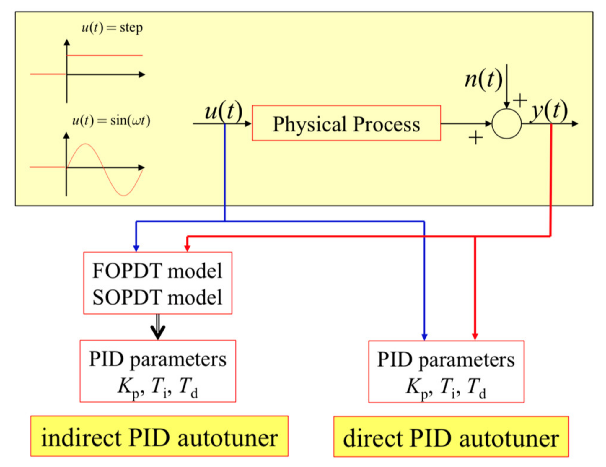
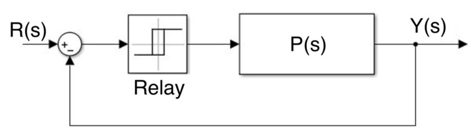
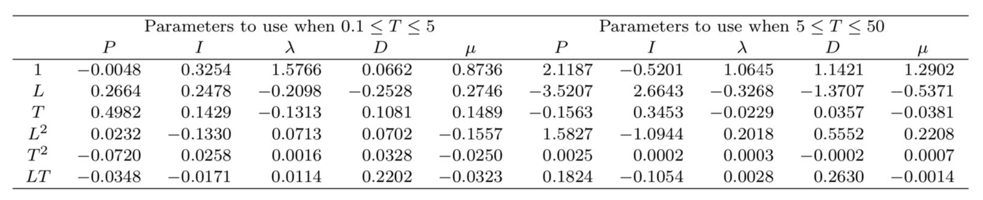
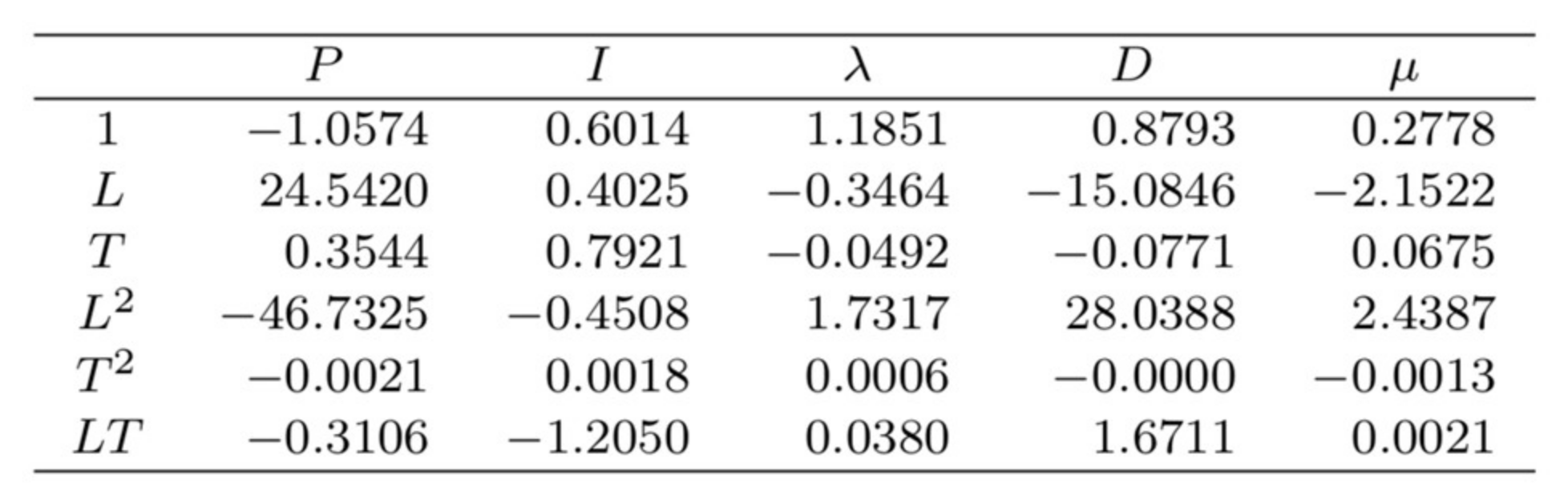
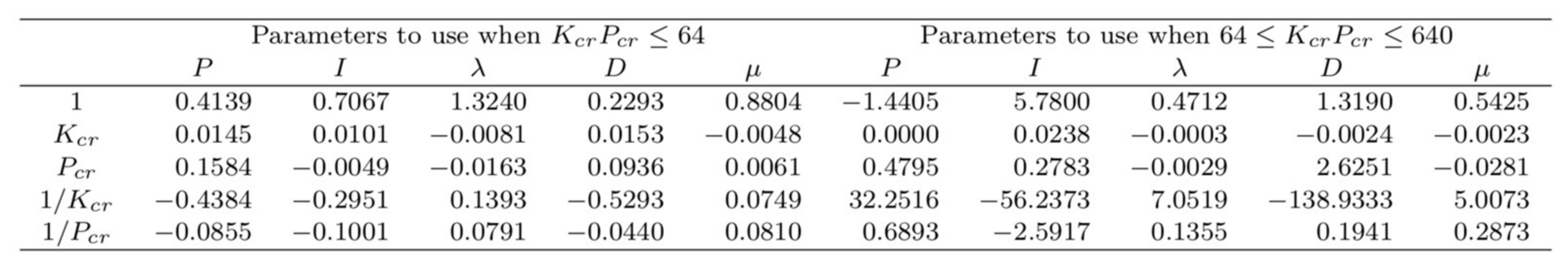
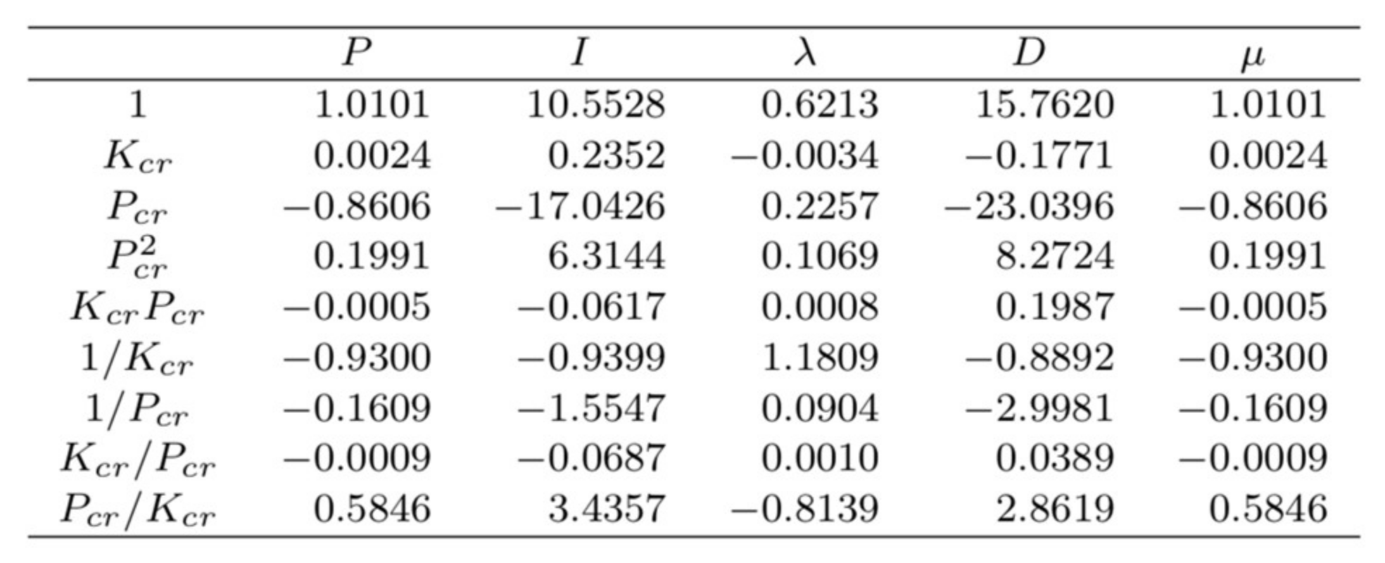
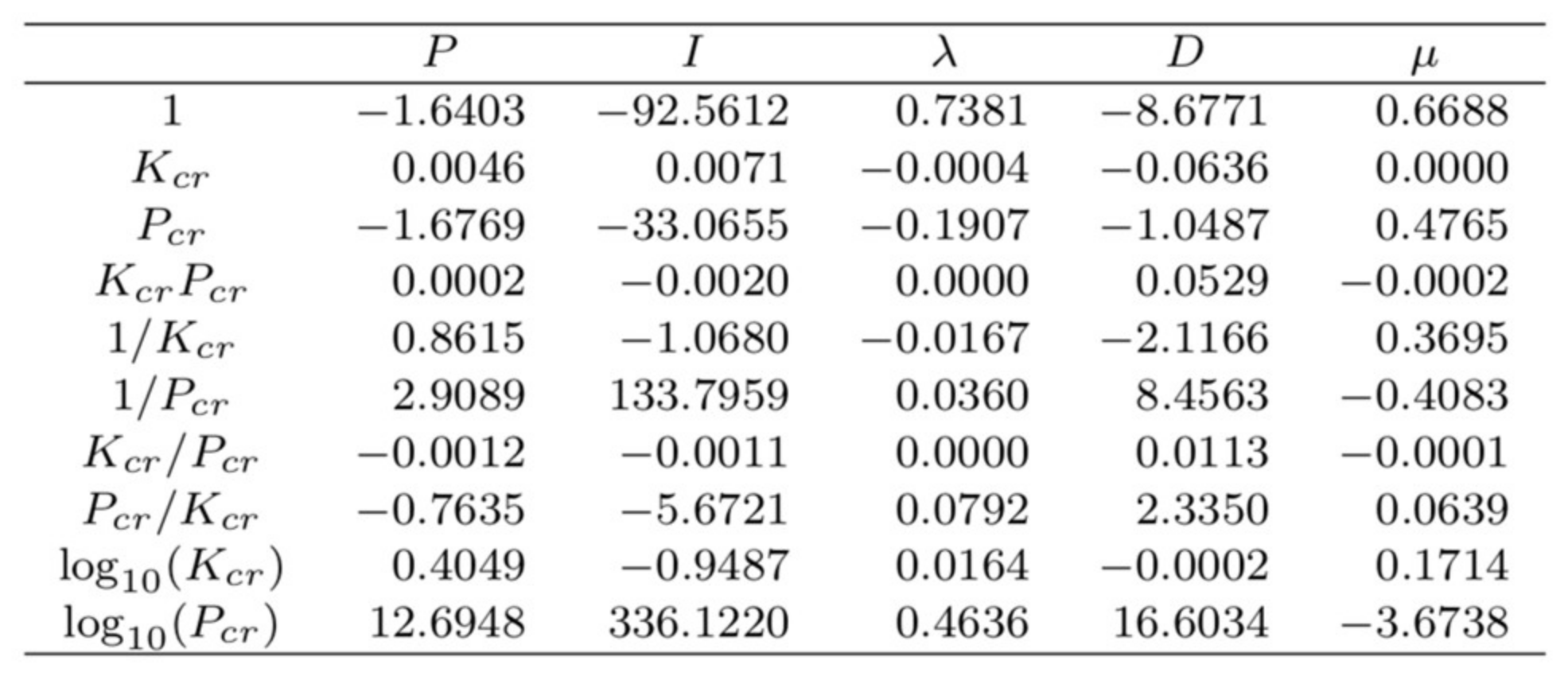
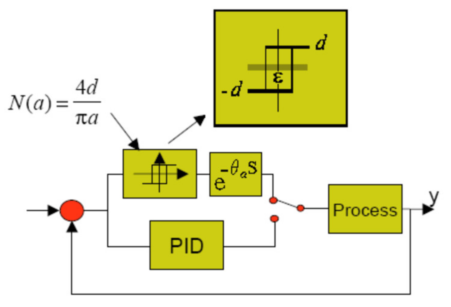
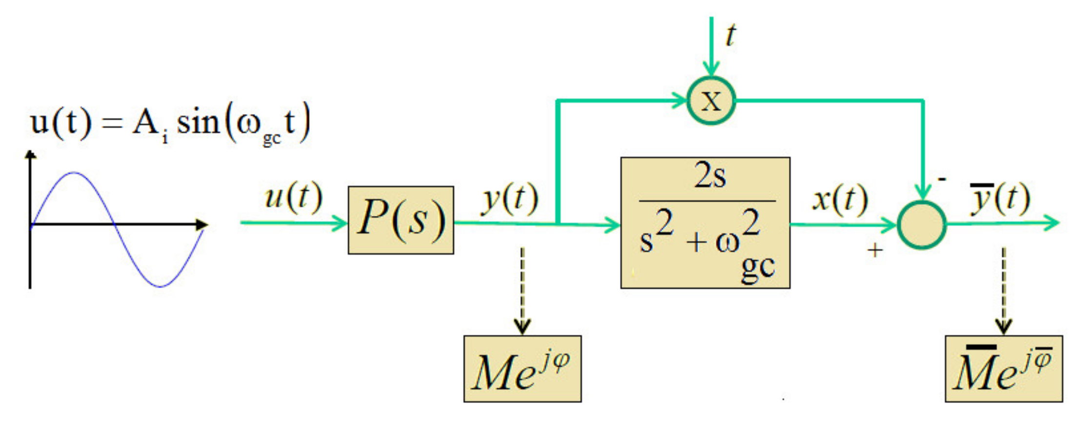
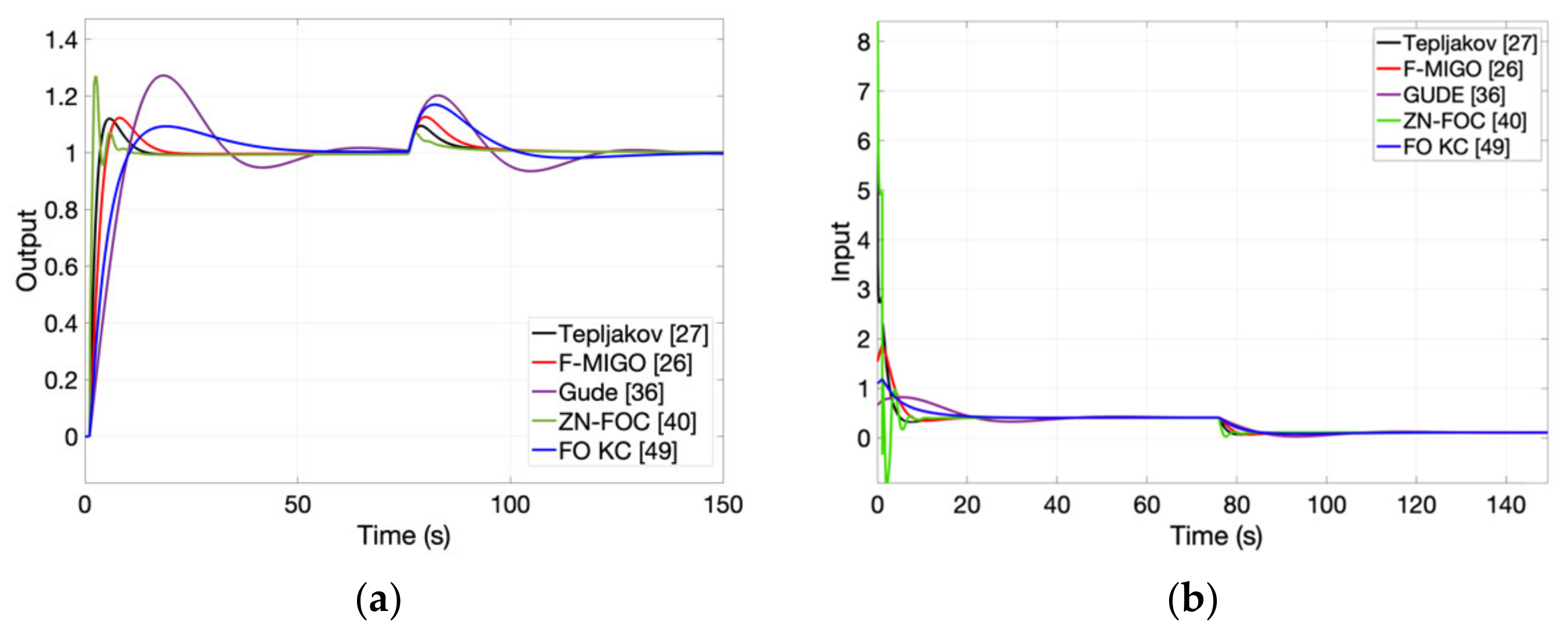
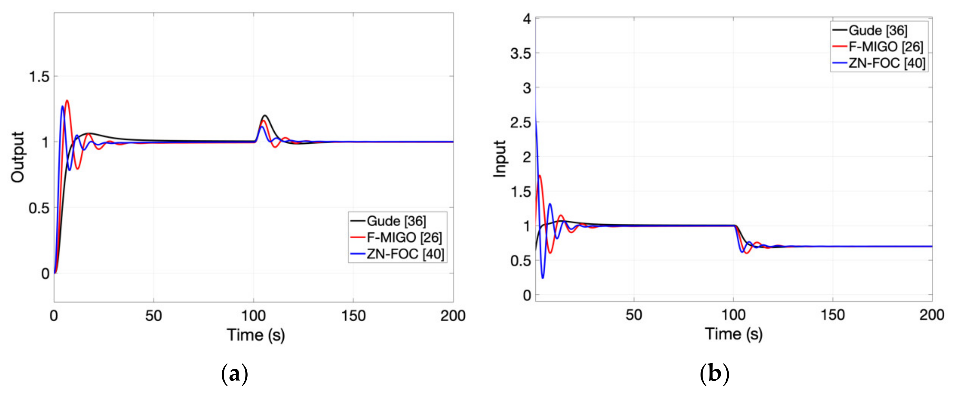
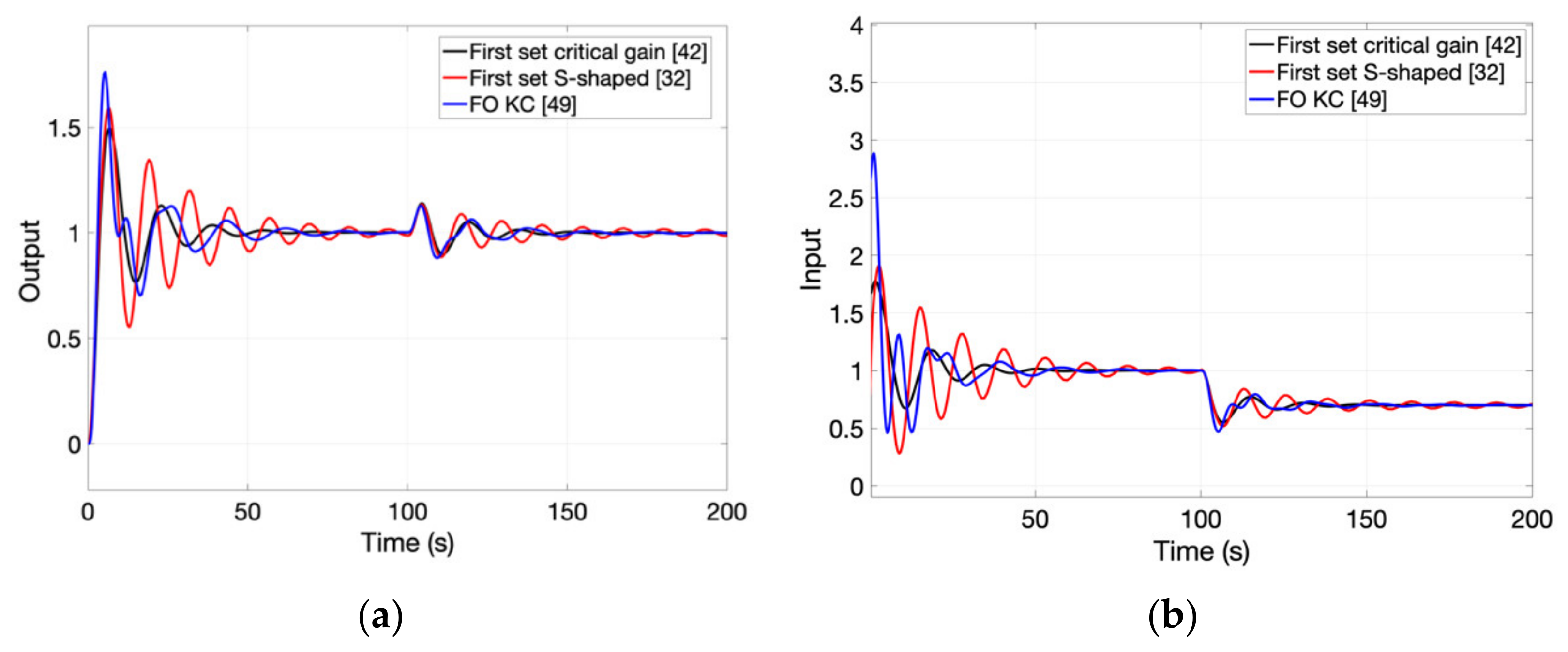
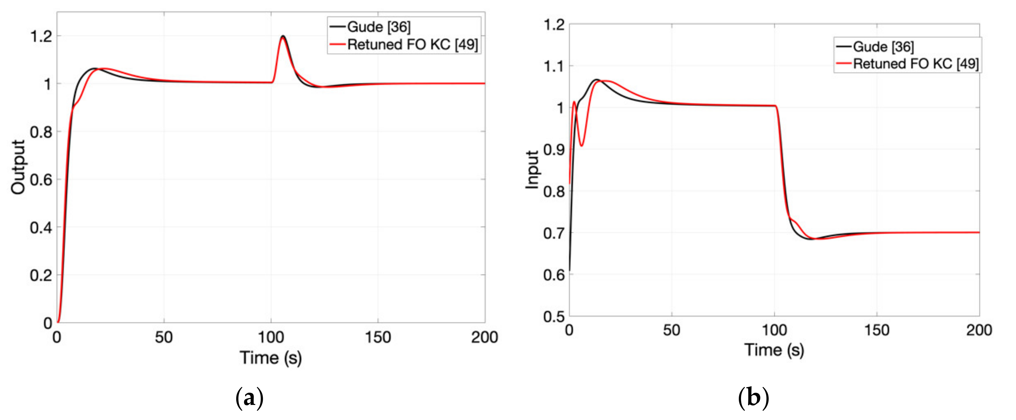
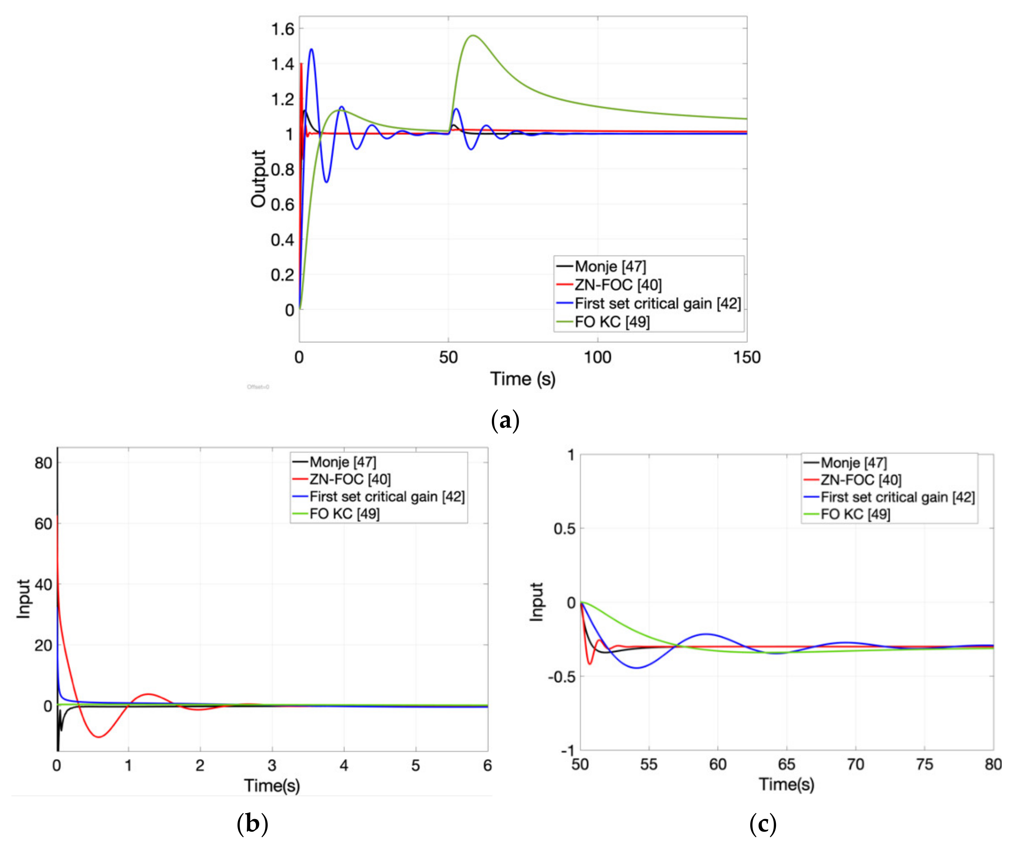
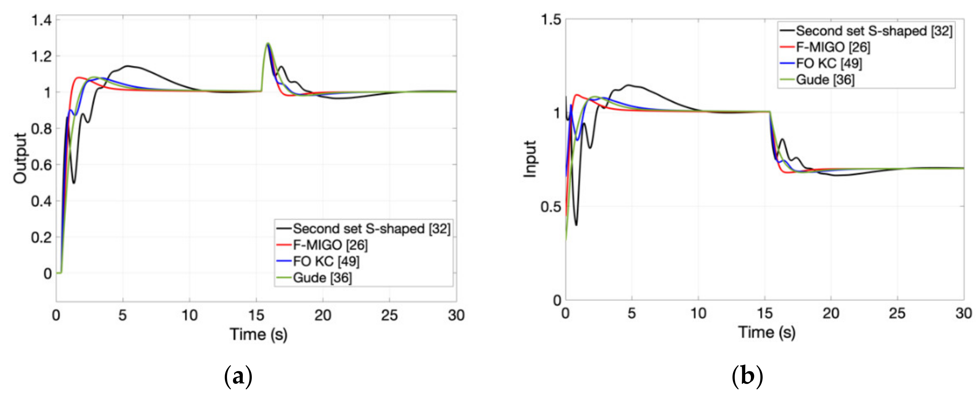
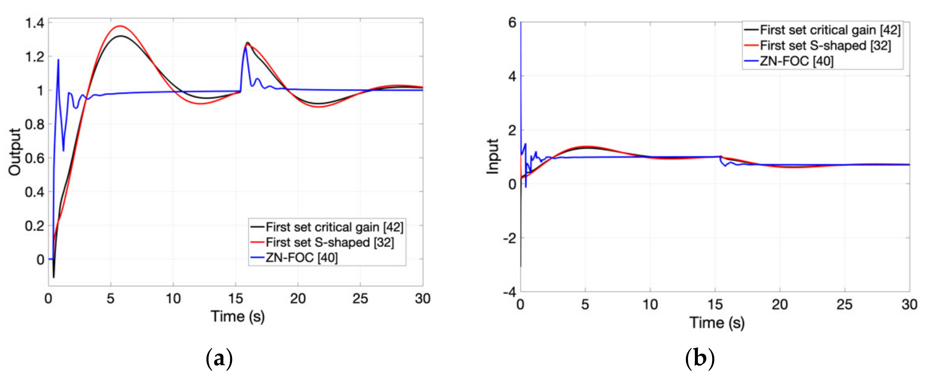
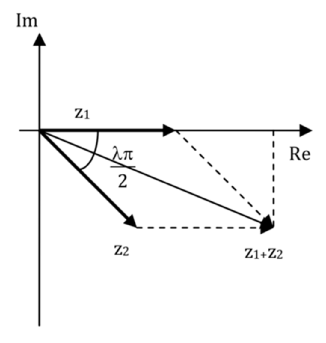
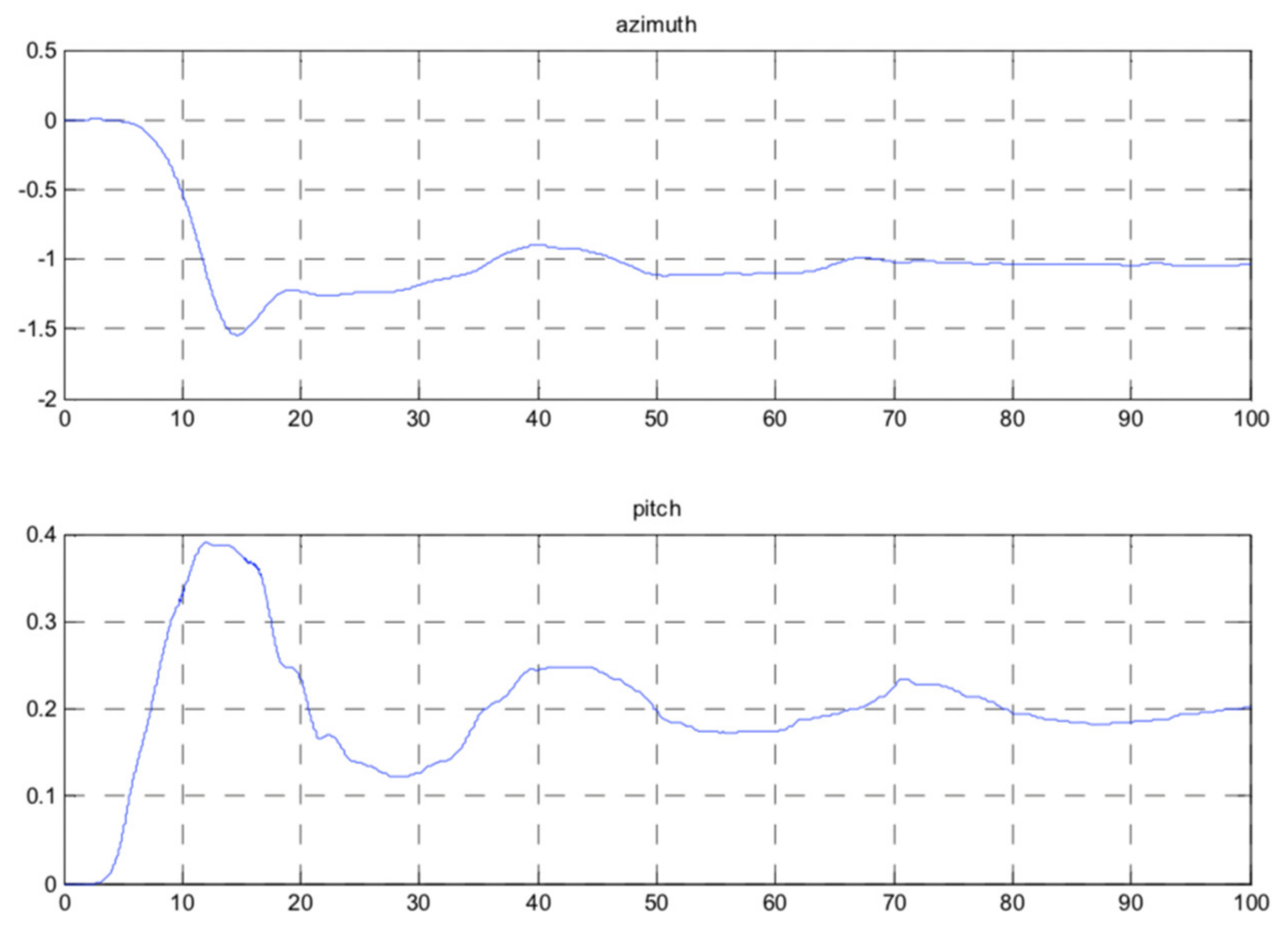
Table 1.
FO-PID parameters according to the modified Ziegler-Nichols method and for different values of the fractional order [40].
Table 1.
FO-PID parameters according to the modified Ziegler-Nichols method and for different values of the fractional order [40].
| kp | Ti | Td | |
|---|---|---|---|
| 0.4 | 0.16 kcr | 0.57 Ti | |
| 0.5 | 0.23 kcr | 0.50 Ti | |
| 0.6 | 0.29 kcr | 0.44 Ti | |
| 0.7 | 0.36 kcr | 0.38 Ti | |
| 0.8 | 0.42 kcr | 0.33 Ti | |
| 0.9 | 0.50 kcr | 0.29 Ti | |
| 1 | 0.6 kcr | 0.25 Ti |
Table 2.
FO-PID parameters computed for the lag-dominant process.
| Controller Type | kp | Ti | Td | ||
|---|---|---|---|---|---|
| FO-PID Tepljakov [27] | 1.9255 | 0.8653 | 0.8 | 0.4010 | 0.6935 |
| FO-PI F-MIGO [26] | 1.5413 | 5.0326 | 0.7 | - | - |
| FO-PI Gude [36] | 0.6641 | 6.6277 | 1.1613 | - | - |
| FO-PID ZN-FOC [40] | 2.8008 | 2.3658 | 0.7 | 0.8990 | 0.7 |
| FO-PID [42] critical first set | 1.1112 | 1.5809 | 1.2298 | 0.5944 | 0.8976 |
| FO-PID [32] S-shaped first set | −5.2747 | 0.8678 | 0.1903 | 1.7823 | −1.5272 |
| FO-PI FO KC [49] | 1.0922 | 13.7410 | 1.15 | - | - |
Table 3.
Closed-loop results obtained with the FO-PID controller for the lag-dominant process.
| Controller | Overshoot | Settling Time | Disturbance Rejection Time |
|---|---|---|---|
| FO-PID Tepljakov [27] | 12% | 11.5 | 13.5 |
| FO-PI F-MIGO [26] | 13% | 15.7 | 17 |
| FO-PI Gude [36] | 28% | 51 | 41.5 |
| FO-PID ZN-FOC [40] | 27% | 7.2 | 10 |
| FO-PI FO KC [49] | 9% | 41 | 23.5 |
Table 4.
FO-PID parameters computed for the higher order process.
| Controller Type | kp | Ti | Td | ||
|---|---|---|---|---|---|
| FO-PI F-MIGO [26] | 0.9093 | 1.7905 | 0.9 | - | - |
| FO-PI Gude [36] | 0.6080 | 3.5486 | 1.13 | - | - |
| FO-PID ZN-FOC [40] | 2 | 3.0847 | 0.9 | 0.5861 | 0.9 |
| FO-PID [42] critical first set | 1.3439 | 2.1448 | 1.2366 | 0.5501 | 0.9311 |
| FO-PID [32] S-shaped first set | 1.1168 | 1.1449 | 1.1 | 1.2152 | 1.0373 |
| FO-PI FO KC [49] | 0.8162 | 4.5733 | 1.18 | - | - |
Table 5.
Closed-loop results obtained with the FO-PID controller for the higher order process.
| Controller | Overshoot | Settling Time | Disturbance Rejection Time |
|---|---|---|---|
| FO-PI F-MIGO [26] | 31% | 33.5 | 17.5 |
| FO-PI Gude [36] | 6.5% | 34.3 | 13.1 |
| FO-PID ZN-FOC [40] | 27% | 23.3 | 12.7 |
| FO-PI FO KC [49] | 6.5% | 42.8 | 13.5 |
Table 6.
FO-PID parameters computed for the integrative time-delay process.
| Controller Type | kp | Ti | Td | ||
|---|---|---|---|---|---|
| FO-PID ZN-FOC [40] | 5.9002 | 2.6760 | 0.4 | 1.5242 | 0.4 |
| FO-PID [42] critical first set | 1.0342 | 1.0606 | 1.0827 | 0.8148 | 0.7855 |
| FO-PID [42] critical third set | 0.4616 | 0.0919 | 0.5929 | −2.7379 | 0.9360 |
| FO-PI FO KC [49] | 0.3812 | 2.7988 | 0.71 | - | - |
Table 7.
Closed-loop results obtained with the FO-PID controller for the integrative time-delay process.
Table 7.
Closed-loop results obtained with the FO-PID controller for the integrative time-delay process.
| Controller | Overshoot | Settling Time | Disturbance Rejection Time |
|---|---|---|---|
| FO-PID ZN-FOC [40] | 40% | 2.3 | 4.5 |
| FO-PID [42] critical first set | 48.5% | 30.7 | 19.1 |
| FO-PI FO KC [49] | 13% | 42 | >70 |
| FO-PID Monje [47] | 13.5% | 5.3 | 3.8 |
Table 8.
FO-PID parameters computed for the integrative time-delay process.
| Controller Type | kp | Ti | λ | Td | μ |
|---|---|---|---|---|---|
| FO-PI F-MIGO [26] | 0.4465 | 0.2951 | 1.1 | - | - |
| FO-PI Gude [36] | 0.3179 | 0.2878 | 1.1187 | - | - |
| FO-PID ZN-FOC [40] | 0.7601 | 0.6420 | 0.9 | 0.1220 | 0.9 |
| FO-PID [42] critical first set | 0.2437 | 0.5649 | 1.4574 | −0.1349 | 1.0028 |
| FO-PID [42] critical second set | −0.0293 | −0.4905 | 1.2668 | 23.7347 | −0.0293 |
| FO-PI FO KC [49] | 0.6573 | 0.3471 | 1.186 | - | - |
| FO-PID [32] S-shaped first set | 0.1994 | 0.4622 | 1.4788 | 0.0845 | 0.9847 |
| FO-PID [32] S-shaped second set | 1.3281 | 1.7653 | 1.3168 | −0.4142 | −0.1793 |
Table 9.
Closed-loop results obtained with the FO-PID controller for the delay-dominant process.
| Controller | Overshoot | Settling Time | Disturbance Rejection Time |
|---|---|---|---|
| FO-PI F-MIGO [26] | 8% | 4 | 1.5 |
| FO-PI Gude [36] | 8.2% | 5.8 | 2.2 |
| FO-PID ZN-FOC [40] | 18% | 5.5 | 2.9 |
| FO-PID [42] critical first set | 32% | 17 | 9.9 |
| FO-PI FO KC [49] | 7.5% | 6.7 | 1.8 |
| FO-PID [32] S-shaped first set | 37.8% | 18.5 | 14.6 |
| FO-PID [32] S-shaped second set | 14.5% | 10.1 | 8.4 |
Publisher’s Note: MDPI stays neutral with regard to jurisdictional claims in published maps and institutional affiliations. |
© 2022 by the authors. Licensee MDPI, Basel, Switzerland. This article is an open access article distributed under the terms and conditions of the Creative Commons Attribution (CC BY) license (https://creativecommons.org/licenses/by/4.0/).
Share and Cite
MDPI and ACS Style
Muresan, C.I.; Birs, I.; Ionescu, C.; Dulf, E.H.; De Keyser, R. A Review of Recent Developments in Autotuning Methods for Fractional-Order Controllers. Fractal Fract. 2022, 6, 37. https://doi.org/10.3390/fractalfract6010037
AMA Style
Muresan CI, Birs I, Ionescu C, Dulf EH, De Keyser R. A Review of Recent Developments in Autotuning Methods for Fractional-Order Controllers. Fractal and Fractional. 2022; 6(1):37. https://doi.org/10.3390/fractalfract6010037
Chicago/Turabian StyleMuresan, Cristina I., Isabela Birs, Clara Ionescu, Eva H. Dulf, and Robin De Keyser. 2022. "A Review of Recent Developments in Autotuning Methods for Fractional-Order Controllers" Fractal and Fractional 6, no. 1: 37. https://doi.org/10.3390/fractalfract6010037