
Hydroforming of High-Strength Aluminum Tubes with Thermo-Mechanical Manufacturing Processes †
by
 ,
,
Ricardo Trân
1,*, 
Jonas Reblitz
2,
Rico Haase
1,
Verena Psyk
1 ,
,
Verena Kräusel
1 and
Marion Merklein
2 1
Fraunhofer Institute for Machine Tools and Forming Technology, Reichenhainer Straße 88, 09126 Chemnitz, Germany
2
Institute for Manufacturing Technology, Friedrich-Alexander-University Erlangen-Nuremberg, Egerland-Straße 13, 91058 Erlangen, Germany
*
Author to whom correspondence should be addressed.
†
Presented at the 28th Saxon Conference on Forming Technology SFU and the 7th International Conference on Accuracy in Forming Technology ICAFT, Chemnitz, Germany, 2–3 November 2022.
Eng. Proc. 2022, 26(1), 13; https://doi.org/10.3390/engproc2022026013
Published: 14 November 2022
(This article belongs to the Proceedings of The 28th Saxon Conference on Forming Technology SFU and the 7th International Conference on Accuracy in Forming Technology ICAFT)
Abstract
:The amount of complex profile components in car bodies increases due to the emerging electromobility. High-strength aluminum alloys are ideally suited as material for automotive applications due to their extraordinary lightweight construction potential. The presented study focuses on the transfer of established thermo-mechanical manufacturing processes for sheet metal components to hydroforming of tube material. Demonstrator components are produced from EN AW-7020 using W-temper-forming and hot forming and compared numerically and experimentally. The results show that the determined material properties are sufficiently accurate to numerically represent the temperature-supported processes with excellent precision. The formed components can be used to demonstrate the potential of hydroforming for high-strength aluminum tubes using W-temper-forming and hot forming.
1. Introduction
In order to reduce vehicle weight and thus the CO2 emissions and energy consumption of electric vehicles, the use of lightweight materials, such as press-hardening steels or highstrength aluminum alloys of the 7xxx series, is indicated. Further vehicle weight can be saved by using tubes and hollow profiles instead of sheet metal semi-finished parts because their structural rigidity and crash resistance make them excellently suitable for car body structures [1]. Hydroforming is an established process for producing hollow profile components with complex cross-sectional geometries [2]. In this process, tubes or hollow profiles are sealed on both ends in a closed tool by hydraulic cylinders, forming medium is filled into the component via the sealing punches and increasing internal pressure forms the component into the cavity. Conventionally, hydroforming is a cold forming process but to increase the formability of low ductility materials it can be applied at elevated temperatures by using heated tools [3,4] and/or preheating strategies for the tubes and profiles [5,6]. In this case, the water-oil emulsion conventionally used as forming medium is replaced by gas in order to prevent liquid forming media from evaporating.
In principle, hydroforming of aluminum is state of the art [7], but high-strength aluminum alloys have been rarely considered in scientific investigations only [8,9]. Contrarily, forming of sheet material from these alloys has been extensively studied [10]. The most important process routes include forming under quenching conditions (hot forming) [11] and W-temper forming [12]. Thus, the objective of this study is to demonstrate the applicability of W-temper forming and hot forming for the hydroforming of tubes by investigating both the numerical design of a hydroforming process for a developed demonstrator component as well as the manufacturing of the component.
2. Materials and Methods
2.1. Specimen Preparation and Experimental Setup for Tensile Tests
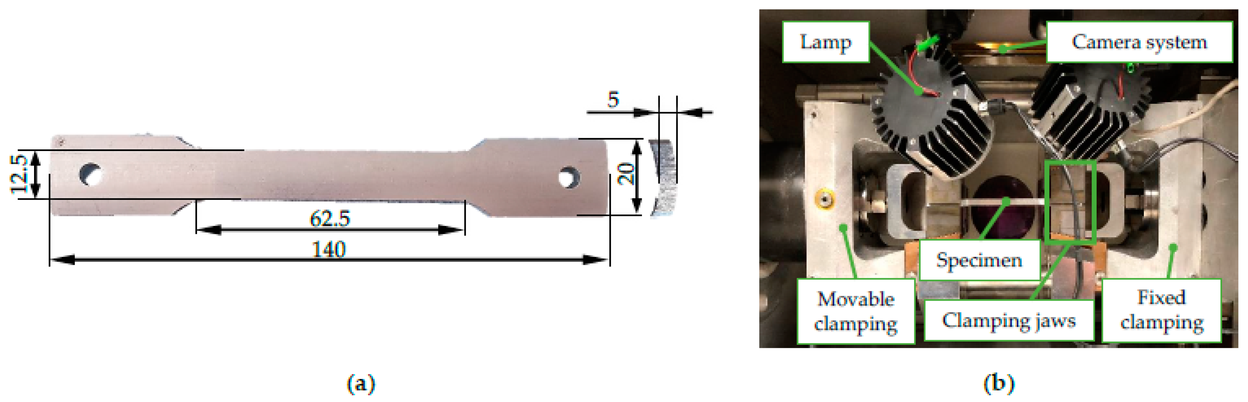
First, the material properties of EN AW-7020 tubes in W-temper condition and for hot forming under quenching conditions were characterized by tensile tests. In this context, tensile specimens were laser cut from the tube material. By inserting a steel sheet, the melting of the inner wall of the tubes by scattered laser beams was avoided. Sections with high surface roughness and thermal influence were removed by milling the edges of the specimens. The resulting geometry was an adapted A50 specimen [13], with additional holes in the clamping area. Due to the tube profile geometry, the tensile specimens have a curvature. Consequently, curved clamping jaws were used to avoid any influence on the strain and stress state during material testing. In earlier tests, the comparability of mechanical properties of such curved and conventional flat tensile specimens had already been proved [14]. Tensile tests were performed by integrating the specimens with the curved clamping jaws into the thermo-mechanical simulator Gleeble 3500, which provides tests at elevated temperatures by conductive heating of the specimens. Since the tests are temperature controlled, the deformation heat is compensated. Strains occurring during the tests were measured by the optical measurement system Aramis (GOM GmbH). The experimental setup and the specimen geometry are shown in Figure 1.
2.2. Material Properties in W-Temper and Hot Forming Condition
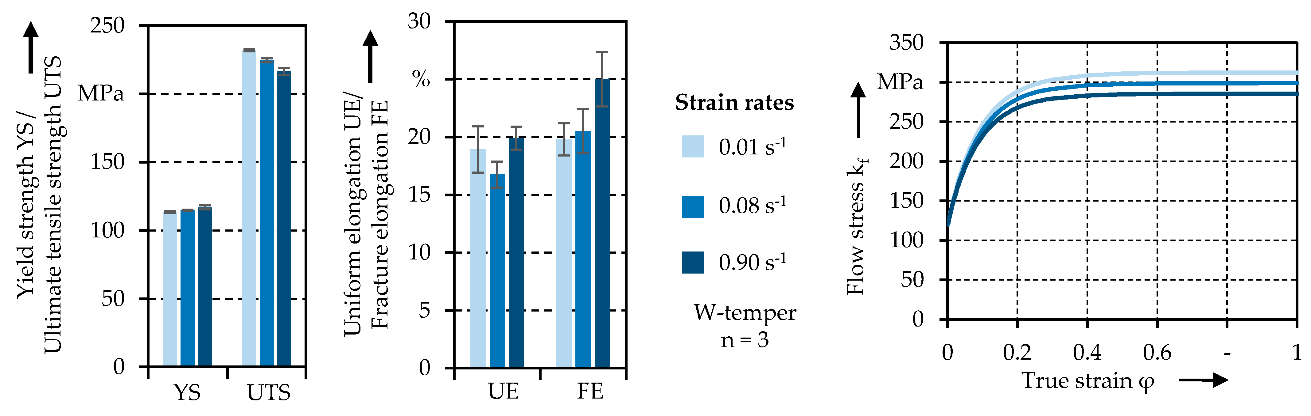
For the transformation of the T6 state into W-temper condition, the tensile specimens were solution annealed at 460 °C for 10 min and quenched in water followed by natural aging for 45 min. It was intended to examine three different strain rates: 0.01 s−1, 0.1 s−1, and 1.0 s−1. However, as the tests were not strain rate controlled, acceleration effects in the experiment led to deviations from the planned strain rates. Due to this, the strain rates were averaged to 0.01 s−1, 0.08 s−1 and 0.90 s−1 to establish a strain rate dependent material model. The corresponding mechanical properties and the extrapolated flow curves are shown in Figure 2. In the context of earlier investigations, significantly lower strength and increased elongations were detected for the W-temper condition compared to the initial T6 state [14]. The tensile strength decreases slightly with increasing strain rates in W-temper condition, while yield strength and elongation at break tend to be constant or slightly increasing. Thus, the material shows a negative strain rate sensitivity in the range of strain rates investigated, which could be explained by the PLC effect [14]. Higher strain rates consequently lead to lower strength.
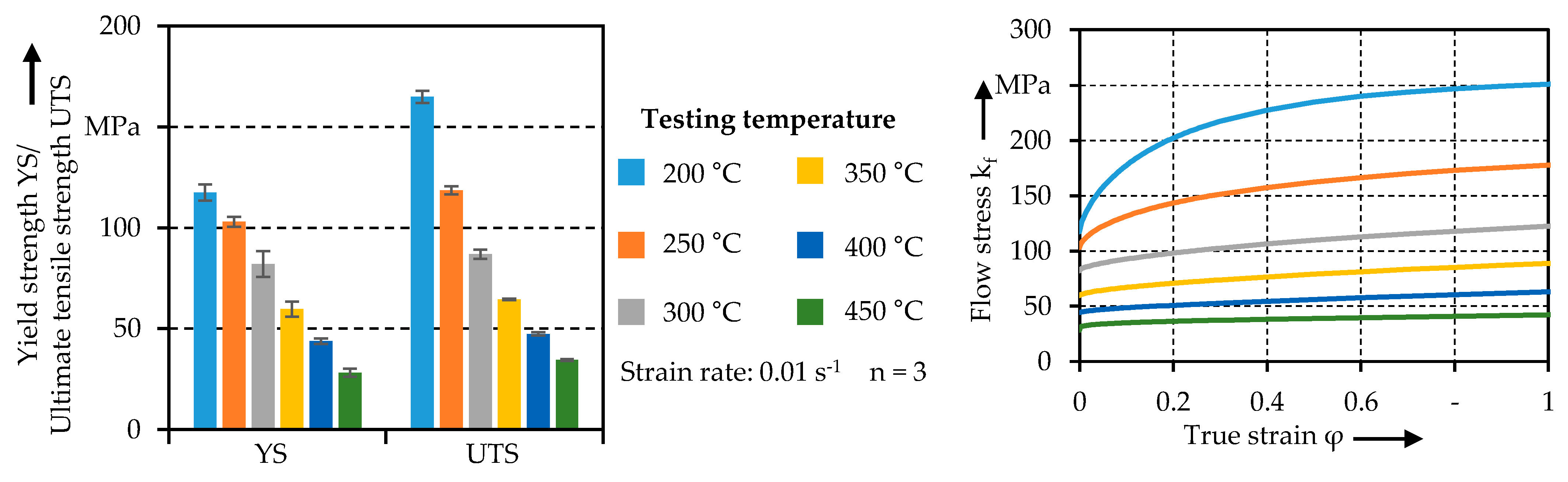
To characterize the hot forming route, the tensile specimens were first solution annealed and quenched according to the W-Temper route and then isothermally tested at temperatures between 200 °C and 450 °C. The temperature of 450 °C corresponds to the forming start temperature after the tube transfer from the furnace to the forming die and closing of the tool. Three strain rates between 0.01 s−1 and 1.00 s−1 were investigated for each temperature. To avoid an uneven temperature distribution due to the conductive heat input, the mechanical properties were only evaluated over a width of 3 mm and not over the full testing length of 50 mm. Therefore, the strains are not shown as they cannot be compared with the cold tensile tests performed to characterize the material behavior in W-temper forming. The temperature-dependent strength and yield curves are shown for a strain rate of 0.01 s−1 in Figure 3.
As expected, the strength decreases continuously with increasing temperature. The tensile strength decreases from 165 MPa at 200 °C to 34 MPa at 450 °C. Based on the flow curves, a weaker strain hardening can be observed with increasing temperature. This might be caused due to growing dynamic recovery and recrystallization. A positive strain rate sensitivity was determined for all tested temperatures. This is most evident at 450 °C, where the tensile strength increases from 34 MPa to 66 MPa within the analyzed strain rates. In summary, a significant reduction in flow resistance can be achieved by hot forming. The parameters for the approximation of the flow curves in Figure 2 and Figure 3 are summarized in Table 1.
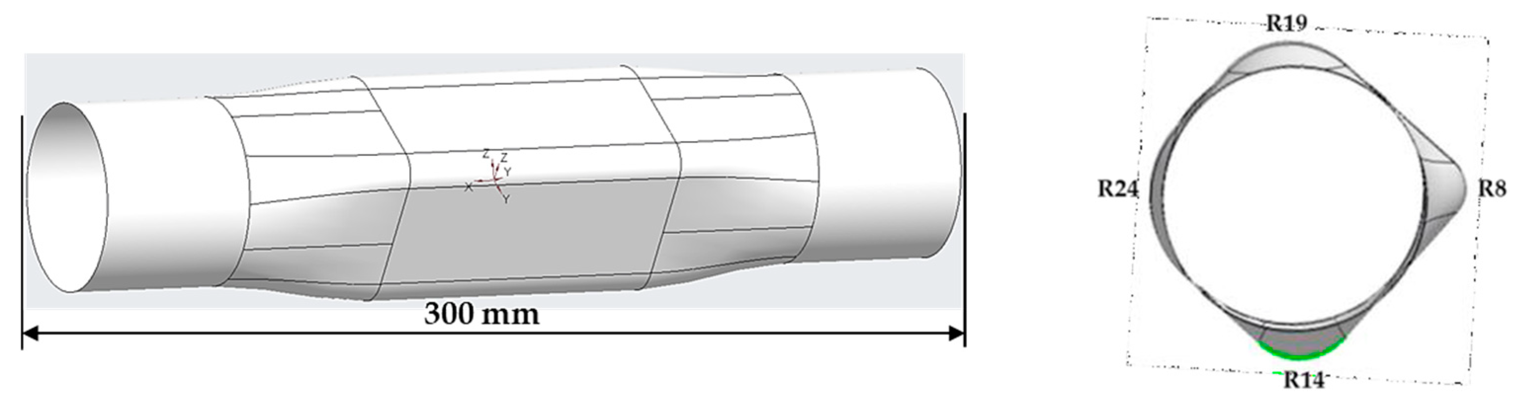
Demonstrator geometry: For the forming process, tubes made of EN AW-7020 T6 with a length of 300 mm, an outer diameter of 60 mm and a wall thickness of 5 mm were used. The relevant demonstrator geometry features a square cross section geometry in the middle with four different corner radii (R8, R14, R19 and R24), as shown in Figure 4. This represents forming conditions of different criticality.
Numerical setup: The hydroforming process in W-temper condition of the EN AW7020 material was performed at room temperature. LS-DYNA was used for the numerical investigations. Accordingly, the numerical model consists of a single, isothermal stage only. The forming tool was represented by a mesh of rigid shell elements. The edge length varied between 2.5 mm in the longitudinal direction and 0.5 mm in the circumferential direction. This resulted in a detailed representation of the radius areas with angle inclination below 3° between neighboring elements. The specimen itself was represented by cuboid volume elements with an edge length of approximately 1.5 mm to 1.8 mm in the thickness direction, 1.2 mm to 1.5 mm in the circumferential direction and 5 mm in the longitudinal direction. The total number of elements of the part was 16,128 distributed on an overall length of 210 mm, where 45 mm were cut away from each end of the physical reference (component sections without expansion). As the sealing of the tube was realized by conical cylinders, no longitudinal movement or even material feeding was possible. The boundary conditions on the front and end face of the specimen were defined accordingly. A contact was defined between the outer side of the tube towards the surrounding cavity. Friction was estimated on Coulomb’s law with a friction coefficient of 0.35, which is a typical value for tempered conditions [15]. During the process, the media pressure was ramped up linearly to a peak value of 320 MPa. Pressure increase velocity was varied between 5, 25 and 45 MPa/s, resulting in build-up times of 64 s, 12.8 s and 7.1 s, respectively. After a short rest, pressure was released in order to observe the final, unloaded shape.
Hydroforming under quenching conditions (hot forming) was based on the previous simulation and shared most of the boundary conditions and assumptions. In contrast to the isothermal strategy, the model consisted of an initial heating stage, a transfer operation and forming stage afterwards. Heating was modelled by a boundary condition with constant increase. Thus, the part was uniformly heated up to 500 °C, resulting in a longitudinal growth of 2.3 mm and a diameter increase of 0.7 mm. This correlates with the thermal expansion coefficient of 23.3 µm/(m × K) and the temperature difference of +475 K. Temperature drop by free convection and radiation to the environment during the handling operation was below 10 K due to the fast transfer and the comparably high wall thickness. In the forming stage, the contact definition between specimen and surrounding cavity consisted of a gap- and pressure-controlled heat transfer algorithm [16].
Experimental setup of the hydroforming trials: Within the investigations W-temper forming (process route I) and hot forming (process route II) were examined:
W-temper forming (process route I): In the W-temper forming process, the tube and hollow profile components were heated up to solution annealing temperature and then quenched in a water bath. This sets the W-temper condition, which increases the coldforming capacity for a short time. The subsequent forming process was a conventional hydroforming process at room temperature with a water-oil emulsion being used as forming medium.
Hot forming (process route II): This method is similar to hot tube gas forming of press hardening steels in terms of the experimental procedure in which tubes are first heattreated in a furnace and then formed and quenched in a cold tool [15]. By combining forming and quenching in one process step, the high component temperature and thus the improved forming properties at the very beginning of the process can first be used for forming the geometry. The coincident quenching then set the material condition that is required for a subsequent ageing treatment to T6 state. Due to the high component temperatures at the beginning of the forming process, nitrogen was used as forming medium.
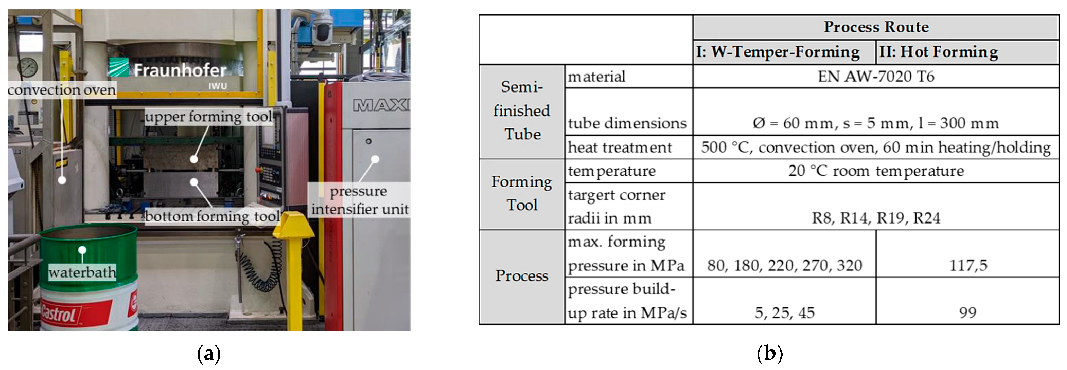
The set-up for the forming experiments, which is shown in Figure 5a, was similar for both process routes and differed only in the additional quenching station for W-temper forming. For both process routes, the tubes were first heated and kept at a solution annealing temperature of approximately 475–500 °C in a convection oven. Due to the high wall thickness of the pipes, a total oven time of 60 min was necessary. For W-temper forming, the tubes were then quenched in a water bath to set the W-temper state and formed in the forming tool with a liquid forming medium. For hot forming, the tubes were moved directly from the furnace into the cold tool. The forming process started 5–8 s after removal from the furnace.
In order to set different maximum strain rates in the forming process and thus to investigate the influence of the strain rate sensitivity of the material on the hydroforming process, different pressure build-up rates were tested for W-temper forming. For hot forming, the maximum achievable pressure build-up rate was used to enable the fastest possible contact of the component with the tool surface and thus rapid quenching. The tested pressure build-up rates as well as the achieved internal pressures in the component are summarized in Figure 5b together with the other process parameters considered in this study. Five different internal component pressures were set for W-temper forming in order to be able to compare intermediate stages of the forming process with the simulation.
3. Results
During the tests, both W-temper forming and hot forming were successfully applied on hydroforming. With W-temper forming, a maximum internal pressure of 320 MPa were achieved. The internal pressures were limited by the maximum axial sealing forces. For hot forming, a maximum internal pressure of 117.5 MPa were achieved, which almost corresponds to the achievable system limit of 120 MPa. The maximum achieved pressure build-up rate was 99 MPa/s. A further variation of the pressure build-up rate was not investigated.
After completing the forming process, 3D coordinate measurement was carried out. The comparison between the experiment and simulation result considering the overall shape of the component and the resulting local wall thickness is shown in Figure 6. Due to the very similar results in both process routes, only one representative component was analyzed, which was produced with W-Temper forming. Figure 6a shows the cross section in the square area of the component. Starting from a wall thickness of 5 mm, obviously significant thinning occurred over the entire cross-section. The flat flank areas contact the tool first, which is why thinning is comparatively low and homogeneous in these areas. Precisely, it varies between 4.65 mm to 4.7 mm. Maximum thinning occurred in the transition area between flank and radius. Corresponding to the largest strains in the area R8, the thinning in the transition area to the flank between R8 and R14 is also the highest with approximately 28% to 3.59 mm. In comparison, Figure 6b shows the predicted thinning from the simulation. It shows that in the radii areas the predicted wall thickness deviates only slightly in the tenth of a millimeter range from the real wall thickness, which indicates a very good prediction accuracy.
The geometric evaluation of the radii areas shows that there are no significant differences in the shape of the radii due to the different process routes. The delta is approximately 0.1 mm in all four radii areas, as Figure 6c shows. The measured values are the average values over all trials (nI = 10, nII = 4). However, the deviation is so small that for both process routes it is possible to speak of a successful and complete forming of the desired component geometry. The investigations show that the determined material characteristics represent the material behavior in the numerical simulation of the forming processes very well. The comparison of the experimental values with the simulation results clearly shows the high prediction accuracy for both W-temper forming and hot forming. Deviations of the predicted wall thicknesses from the measured experimental results can be explained by the fact that the wall thickness of the tubes used did not correspond to the nominal value of 5.0 mm, but the average value was approximately 5.1 mm. In addition, the continuously changing friction conditions due to aluminum adhesion in the tool needs to be mentioned, which also leads to deviations in the forming accuracy. The assumed friction value of 0.35 has already been used in other published investigations [15] but does not reflect the changing friction conditions during the process.
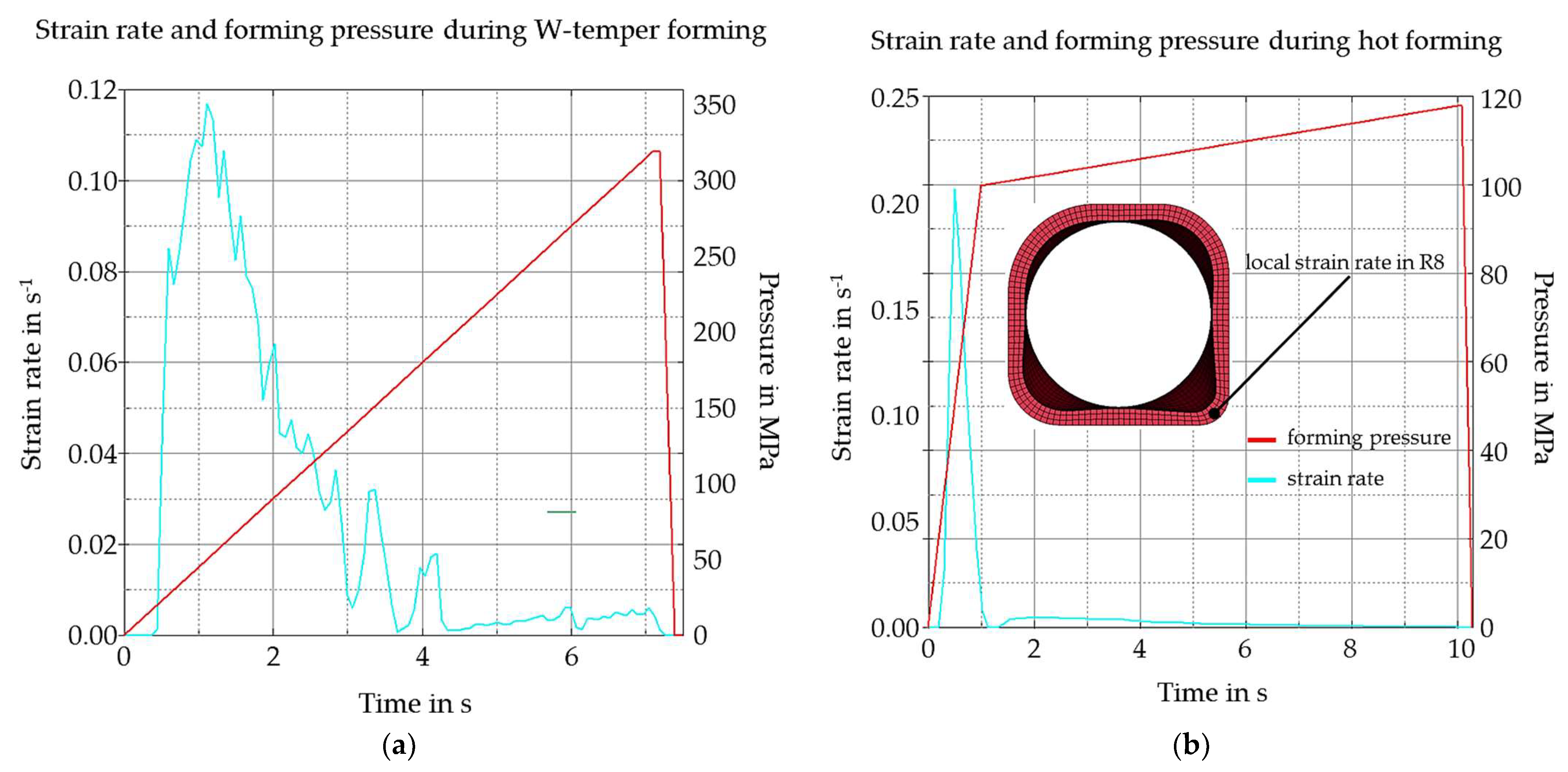
The investigated strain rates of 0.01 s−1 to approximately 1 s−1 represent the local strain rates occurring during the process very well, as can also be seen in Figure 7. Corresponding to the investigated pressure build-up rates of 5, 25, 45 and 99 MPa/s, respectively, strain rates up to approximately 0.12 s−1 during W-temper forming and 0.2 s−1 during hot forming occur locally in the component area with the largest deformation (radius R8). In reference to the mentioned results of the geometrical analysis of the parts, an influence on the formability or the achieved geometric accuracies was not determined so that the strain rate dependence has no significant influence on the process, at least in the considered strain rate range. Depending on the component geometry, however, significantly higher strain rates can occur in hydroforming processes, so the strain rate dependency must be taken into account and the determination of the material characteristics must be carried out at corresponding strain rates.
4. Discussion
The comparison between W-temper forming and hot forming regarding component shape and geometric accuracies does not show any significant differences so that no preferred variant can be derived for the production of the component on the basis of the geometric evaluation. From a process-technical point of view, however, there are significant differences: Quenching in a water bath during W-temper forming is impractical for series application, because it requires an additional cooling section in the production line. Especially in case of thick-walled tubes, it is important that active cooling takes place both from the outside and inside the tube in order to ensure homogeneous cooling. Otherwise, a considerable variation of the material properties over the wall thickness is possible. The additional cooling station leads to higher process costs and larger space requirements in production. On the other hand, by W-temper forming it is possible to use lubricants to improve the friction conditions between the tool and the component. This can be an advantage, especially when using aluminum alloys, as otherwise tool wear is relatively high due to aluminum adhesion on the tool surfaces and the forming process deteriorates. Aluminum adhesion on the tool surfaces due to forming were also observed in the experiment. Aluminum is adhered to both on the sealing plunges and the inlet areas. In a series production with more components, this issue needs to be addressed.
Hot forming would save the quenching process with water and thus shorten the process chain. However, the tool design is more demanding, as the active parts would have to be actively cooled for series production. Due to the high insert temperatures between 470 °C and 500 °C, the aluminum also tends to adhere even more to the tool surfaces, which results in increased tool wear compared to W-temper forming. The use of lubricants or release agents is only possible to a limited extent due to the high component temperatures during insertion.
However, there is a significant difference considering the process parameters used in each case. The tests show that hot forming with one third of the internal pressure achieves similarly good forming results. From an economic and ecological point of view, it is therefore necessary to compare the respective media used: the water-oil emulsion used for Wtemper forming is more cost-effective than the nitrogen used for hot forming. Nevertheless, the high internal pressures that can be achieved with W-temper forming require appropriate press technology. The lower internal pressures for hot forming allow using presses with lower clamping force. Only an additional high-pressure intensifier unit is required to build up the internal pressure. The selection of the best process for hydroforming of precipitation-hardenable aluminum alloys from a cost and sustainability point of view is therefore very product-specific.
5. Conclusions
The investigations have shown that both W-temper forming and hot forming (forming under quenching conditions) can be applied with hydroforming to produce complex profile geometries. It became clear that the material properties determined for EN AW7020 were very suitable for creating simulation models for the numerical representation of the two process routes. The comparison of simulation and experimental results showed that the prediction accuracy is very good and that the simulation models are appropriate for the design of the forming processes. In the experimental implementation it became clear that both process variants approaches are equally suitable for producing the developed demonstrator component. However, regarding an evaluation of the usability for industrial implementation, the aspects of process complexity and sustainability should not be disregarded. In hot forming, for example, high tool wear and high nitrogen consumption are disadvantageous. On the other hand, W-temper forming requires very high forming pressures (up to 320 MPa) and clamping forces, which require appropriate plant equipment.
Further investigations should look at the ageing behavior of formed specimens. Due to the high wall thickness and the resulting different cooling states over the wall thickness, a gradation of the material properties can follow after the ageing treatment.
Author Contributions
Conceptualization, R.T. and J.R.; methodology, R.T.; software, R.H.; validation, R.T. and R.H.; formal analysis, R.T.; investigation, R.T., J.R. and R.H.; resources, V.K. and M.M.; writing—original draft preparation, R.T.; writing—review and editing, V.P. and M.M.; supervision, V.P., V.K. and M.M.; project administration, R.T. and J.R.; funding acquisition, V.K. and M.M. All authors have read and agreed to the published version of the manuscript.
Funding
This research was funded by the German Federation of Industrial Research Associations AiF, grant number 21434BG.
Institutional Review Board Statement
Not applicable.
Informed Consent Statement
Not applicable.
Data Availability Statement
Not applicable.
Acknowledgments
The authors would like to thank Albert Schmutzler Schnitt- und Stanzwerkzeuge GbR for providing the forming tools used in this study.
Conflicts of Interest
The authors declare no conflict of interest.
References
- Bell, C.; Corney, J.; Zuelli, N.; Savings, D. A state of the art review of hydroforming technology. Int. J. Mater. Form. 2020, 13, 789–828. [Google Scholar] [CrossRef] [Green Version]
- Neugebauer, R. Hydro-Umformung, 1st ed.; Springer: Berlin/Heidelberg, Germany, 2007; ISBN 978-3-540-49013-5. [Google Scholar]
- Trân, R.; Reuther, F.; Winter, S.; Psyk, V. Process Development for a Superplastic Hot Tube Gas Forming Process of Titanium (Ti-3Al-2.5V) Hollow Profiles. Metals 2020, 10, 1150. [Google Scholar] [CrossRef]
- Paul, A.; Werner, M.; Trân, R.; Landgrebe, D. Hot metal gas forming of titanium grade 2 bent tubes. In AIP Conference Proceedings, Proceedings of the 20th International ESAFORM Conference on Material Forming: ESAFORM 2017, Dublin, Ireland, 26–28 April 2017; Brabazon, D., Naher, S., Ahad, I.U., Eds.; AIP Publishing: Melville, NY, USA, 2017; ISBN 978-0-7354-1580-5. [Google Scholar]
- Bach, M.; Degenkolb, L.; Reuther, F.; Psyk, V.; Demuth, R.; Werner, M. Conductive Heating during Press Hardening by Hot Metal Gas Forming for Curved Complex Part Geometries. Metals 2020, 10, 1104. [Google Scholar] [CrossRef]
- Landgrebe, D.; Albert, A.; Reuther, F.; Paul, A. Press Hardening of Tubes by Hot Metal. Gas. Forming. In Proceedings of the 2nd Sino-German Workshop, Dresden, Germany, 17–21 July 2018; Available online: https://publica.fraunhofer.de/handle/publica/400983 (accessed on 28 July 2022).
- Zheng, K.; Zheng, J.-H.; He, Z.; Liu, G.; Politis, D.J.; Wang, L. Fundamentals, processes and equipment for hot medium pressure forming of light material tubular components. Int. J. Lightweight Mater. Manuf. 2020, 3, 1–19. [Google Scholar] [CrossRef]
- Lee, M.-Y.; Sohn, S.-M.; Kang, C.-Y.; Suh, D.-W.; Lee, S.-Y. Effects of pre-treatment conditions on warm hydroformability of 7075 aluminum tubes. J. Mater. Processing Technol. 2004, 155–156, 1337–1343. [Google Scholar] [CrossRef]
- Hartl, C. Research and advances in fundamentals and industrial applications of hydroforming. J. Mater. Process. Technol. 2005, 167, 383–392. [Google Scholar] [CrossRef]
- Zheng, K.; Politis, D.J.; Wang, L.; Lin, J. A review on forming techniques for manufacturing lightweight complex—Shaped aluminium panel components. Int. J. Lightweight Mater. Manuf. 2018, 1, 55–80. [Google Scholar] [CrossRef]
- Foster, A.; Dean, T.A.; Lin, J. Process for Forming Aluminium Alloy Sheet Components. WO2010032002A1, 16 September 2009. [Google Scholar]
- de Argandoña, E.S.; Galdos, L.; Ortubay, R.; Mendiguren, J.; Agirretxe, X. Room Temperature Forming of AA7075 Aluminum Alloys: W-Temper Process. KEM 2015, 651–653, 199–204. [Google Scholar] [CrossRef]
- DIN EN ISO 6892-1:2020-06; Metallische Werkstoffe-Zugversuch-Teil 1: Prüfverfahren bei Raumtemperatur. ISO: Geneva, Switzerland, 2020.
- Reblitz, J.; Reuther, F.; Trân, R.; Kräusel, V.; Merklein, M. Numerical and Experimental Investigations on the Mechanical Properties of Milled Specimens from an AA7020 Tube. KEM 2022, 926, 1949–1958. [Google Scholar] [CrossRef]
- Paul, A.; Reuther, F.; Neumann, S.; Albert, A.; Landgrebe, D. Process simulation and experimental validation of Hot Metal Gas Forming with new press hardening steels. J. Phys. Conf. Ser. 2017, 896, 12051. [Google Scholar] [CrossRef]
- Shapiro, A.B. Using LS-Dyna for Hot Stamping. In Proceedings of the 7th European LS-DYNA Conference, Salzburg, Austria, 14–15 May 2009. [Google Scholar]
Figure 1.
(a) Geometry of the tensile specimens. (b) Experimental setup of the thermo-mechanical simulator Gleeble 3500.
Figure 1.
(a) Geometry of the tensile specimens. (b) Experimental setup of the thermo-mechanical simulator Gleeble 3500.

Figure 2.
Mechanical properties and flow curves of AA7020 in W-temper condition for different strain rates.
Figure 2.
Mechanical properties and flow curves of AA7020 in W-temper condition for different strain rates.

Figure 3.
Mechanical properties and flow curves of AA7020 in hot forming condition for different temperatures.
Figure 3.
Mechanical properties and flow curves of AA7020 in hot forming condition for different temperatures.

Figure 4.
Developed demonstrator component with square geometry with different radii from R8 to R24. Length (l) = 300 mm, initial outer diameter = 60 mm, wall thickness (s) = 5.0 mm.
Figure 4.
Developed demonstrator component with square geometry with different radii from R8 to R24. Length (l) = 300 mm, initial outer diameter = 60 mm, wall thickness (s) = 5.0 mm.

Figure 5.
(a) Experimental set-up for hydroforming trials for both process routes. (b) Specified test parameters and general conditions for the experimental trials.
Figure 5.
(a) Experimental set-up for hydroforming trials for both process routes. (b) Specified test parameters and general conditions for the experimental trials.

Figure 6.
(a) Central cross-section of the formed component with locally measured wall thickness in mm. (b) Cross-section of the simulated component geometry in the square area with locally predicted wall thickness in mm. (c) Comparison of forming accuracy between process route I and II.
Figure 6.
(a) Central cross-section of the formed component with locally measured wall thickness in mm. (b) Cross-section of the simulated component geometry in the square area with locally predicted wall thickness in mm. (c) Comparison of forming accuracy between process route I and II.

Figure 7.
(a) Strain rate and forming pressure diagram for pressure build-up rate of 45 MPa/s, maximum inner pressure of 320 MPa, W-temper condition. (b) Strain rate and forming pressure diagram for pressure build-up rate of 99 MPa/s, maximum inner pressure of 117.5 MPa, hot forming.
Figure 7.
(a) Strain rate and forming pressure diagram for pressure build-up rate of 45 MPa/s, maximum inner pressure of 320 MPa, W-temper condition. (b) Strain rate and forming pressure diagram for pressure build-up rate of 99 MPa/s, maximum inner pressure of 117.5 MPa, hot forming.


Table 1.
Parameters of the flow curve approximation according to Hockett–Sherby.
| Equation for the Flow Curve Approximation: kf = b − (b − a) · e −cφd | ||||
|---|---|---|---|---|
| Flow Curve | a in MPa | b in MPa | c | d |
| W-temper 0.01 s−1 | 113.66 | 298.49 | 11.8749 | 0.9858 |
| W-temper 0.08 s−1 | 114.90 | 290.31 | 12.6919 | 1.0171 |
| W-temper 0.90 s−1 | 116.85 | 280.71 | 11.4966 | 0.9896 |
| Hot forming 200 °C | 117.50 | 258.926 | 3.0588 | 0.7329 |
| Hot forming 250 °C | 103.04 | 213.59 | 1.6019 | 0.6342 |
| Hot forming 300 °C | 82.17 | 1471.82 | 0.5279 | 0.6987 |
| Hot forming 350 °C | 59.73 | 5624.20 | 0.0509 | 0.6153 |
| Hot forming 400 °C | 43.81 | 8538.09 | 0.0638 | 0.6778 |
| Hot forming 450 °C | 28.35 | 79866.21 | 0.0003 | 0.3474 |
Publisher’s Note: MDPI stays neutral with regard to jurisdictional claims in published maps and institutional affiliations. |
© 2022 by the authors. Licensee MDPI, Basel, Switzerland. This article is an open access article distributed under the terms and conditions of the Creative Commons Attribution (CC BY) license (https://creativecommons.org/licenses/by/4.0/).
Share and Cite
MDPI and ACS Style
Trân, R.; Reblitz, J.; Haase, R.; Psyk, V.; Kräusel, V.; Merklein, M. Hydroforming of High-Strength Aluminum Tubes with Thermo-Mechanical Manufacturing Processes. Eng. Proc. 2022, 26, 13. https://doi.org/10.3390/engproc2022026013
AMA Style
Trân R, Reblitz J, Haase R, Psyk V, Kräusel V, Merklein M. Hydroforming of High-Strength Aluminum Tubes with Thermo-Mechanical Manufacturing Processes. Engineering Proceedings. 2022; 26(1):13. https://doi.org/10.3390/engproc2022026013
Chicago/Turabian StyleTrân, Ricardo, Jonas Reblitz, Rico Haase, Verena Psyk, Verena Kräusel, and Marion Merklein. 2022. "Hydroforming of High-Strength Aluminum Tubes with Thermo-Mechanical Manufacturing Processes" Engineering Proceedings 26, no. 1: 13. https://doi.org/10.3390/engproc2022026013