Article

Investigation of Energy and Environmental Potentials of a Renewable Trigeneration System in a Residential Application

1
Renewable Energy Department, Korea Institute of Energy Research, Daejeo 305-343, Korea
2
Natural Resources Canada, CanmetENERGY, 1 Haanel Drive, Ottawa, ON K1A 1M1, Canada
3
TapSol, 591 Yulam-ri, Paltan-myeon, Hwasung-si, Gyeonggi-do 445-913, Korea
*
Author to whom correspondence should be addressed.
Energies 2016, 9(9), 760; https://doi.org/10.3390/en9090760
Submission received: 29 June 2016 / Revised: 9 August 2016 / Accepted: 12 September 2016 / Published: 20 September 2016
(This article belongs to the Special Issue Renewable Energy Technologies for Small Scale Applications)

Abstract

:
Micro polygeneration utilizing renewable energy is a suitable approach to reduce energy consumption and carbon emission by offering high-efficiency performance, offsetting the need for centrally-generated grid electricity and avoiding transmission/distribution losses associated with it. This paper investigates the energy and environmental potential of a renewable trigeneration system in a residential application under Incheon (Korea) and Ottawa (Canada) weather conditions. The trigeneration system consists of a ground-to-air heat exchanger (GAHX), photovoltaic thermal (PVT) panels and an air-to-water heat pump (AWHP). The study is performed by simulations in TRNSYS (Version 17.02) environment. The performance of the trigeneration system is compared to a reference conventional system that utilizes a boiler for space and domestic hot water heating and a chiller for space cooling. Simulation results showed substantial annual primary energy savings from the renewable trigeneration system in comparison to the reference system—45% for Incheon and 42% for Ottawa. The CO2eq emission reduction from the renewable trigeneration system is also significant, standing at 43% for Incheon and 82% for Ottawa. Furthermore, trigeneration systems’ capability to generate electricity and thermal energy at the point of use is considered as an attractive option for inclusion in the future smart energy network applications.

1. Introduction

Small combined heat and power (CHP) systems or so-called micro-cogeneration are able to generate power and heat at the point of use by utilizing a variety of conventional and renewable technologies. Micro-cogeneration systems (with an electric output lower than 50 kWel according to [1]) are emerging as a suitable approach to reduce energy consumption and pollutant emissions by offsetting the need for centrally-generated grid electricity, enhancing energy security and avoiding transmission/distribution losses [2,3,4,5,6,7,8,9,10,11,12,13,14,15,16,17,18,19,20,21,22,23,24,25,26]. In recent years, significant advances have been achieved in the development, design, and optimization of micro CHP systems such as micro-turbine [6,7], internal combustion engine [8,9,10,11,12,13], organic Rankine cycle [6,14,15], Stirling engine [8,16,17,18], fuel cell [7,19,20,21,22,23,24,25] and photovoltaic thermal (PVT) [8,19,26].
In addition to the micro-cogeneration technologies, several studies have recognized that the ground source heat pump (GSHP) is an efficient and environmentally friendly option for space heating/cooling of buildings [27,28,29,30]. A large number of GSHPs have been used in residential and commercial buildings throughout the world [30]. The GSHP performance is still a subject of on-going research efforts, since it is affected by physical parameters (e.g., heat reservoir temperature and geological characteristics of the site), operation characteristics (e.g., the time distribution of the cooling/heating demand), as well as construction and qualitative characteristics of the system [29,30]. Lee et al. [31] explored an optimization method that factors the impact of ICT (information and communication technologies) on improving the GSHP performance. Several other studies [32,33,34,35] have investigated energy, cost and environmental performance of trigeneration systems (heating, cooling and power) that integrate water-to-water GSHP with fuel cell and PVT technologies respectively.
Ground-to-air heat exchange (GAHX) is one of the technology options for green buildings that utilize various concepts for natural heating, ventilation and air-conditioning [36]. GAHX system is usually used in colder countries in Europe and America [37] for cooling and heating. GAHX takes advantage of constant ground temperatures to precondition incoming fresh air hence reducing the heating and cooling loads. The earth’s surface ground temperature remains relatively constant at a depth of 1.5–2.0 m [38]. When the fresh air passes through the GAHX pipelines, it is pre-cooled with cooler ground temperature in the summer and pre-warmed with the ground heat in winter by using the thermal potential of the ground. The energy required for cooling or heating the building reduces significantly by using GAHX system when the difference between outdoor temperature and the comfortable indoor temperature is small. In addition, the use of GAHX downsizes the heating and cooling equipment capacities.
To further reduce the energy consumption, new initiatives have been launched around the world. Passive house has been introduced in European countries such as Germany and Switzerland to enhance the low energy buildings concept [39]. Renewable heat obligation (RHO) has been implemented in Republic of Korea for public sector buildings larger than 10,000 m2 to reduce heating energy consumption by at least 11% between 2015 and 2030 [40]. The passive house standard calls for air tightness ≤0.6 air change per hour (ACH) and maximum space heating load for residential building ≤15 kWh/m2·year [41]. Therefore, the passive house can be equipped with geothermal systems which integrating heat pump with a ground-to-air heat exchanger to meet the cooling and heating load demands.
Chel et al. [42] simulated multi-zone building to investigate the thermal performance of integrated air-air heat exchanger (AAHE) and earth-water heat exchanger (EWHE) for a passive house. They concluded that AAHE and EWHE systems were able to provide 72% reduction in annual heating consumption with an energy intensity of 6.9 kWh/m2·year, which was within the passive house standard. The effect of the earth tube heat exchanger on the energy saving for a small house, row houses and a small office building was investigated under three different climate conditions [42]. The results from their simulations showed increased energy saving between 2.2 and 9.4 kWh/m2 for the small house, between 1.3 and 4.1 kWh/m2 for the row houses, and 0.7 kWh/m2 for the small office building. The geothermal system is able to save 43% and 37% of the primary energy consumption during the heating and cooling seasons, respectively [43].
Photovoltaic thermal (PVT) is another technology that can be integrated into microgeneration systems [33,34,35]. The dual functions of the PVT system result in a higher overall solar conversion rate than that of solely photovoltaic or solar collectors, thus enabling a more effective use of solar energy. Currently, the number of commercially available collectors and systems are still very limited. Major barriers such as product reliability and costs remain to breakthrough [44,45], but PVT devices are expected to have major market expansion potentials in the near future [44]. Significant activities are still required in terms of PVT energy conversion and its effectiveness, thermal absorber design and fabrication, material and coating selection, performance testing, cost minimization, system optimization, control and reliability [44,45].
Although micro CHP, GSHP and PVT are exciting technologies, they are still facing several challenges, in gaining shares in mature and competitive markets, in further improving of devices efficiency and reducing cost, in increasing the operational lifetime to recover the initial investment, and also in understanding the systems both by installers and potential end users.
High purchase cost is the main barrier for larger penetration of the above-mentioned technologies in residential applications. Most of these technologies are in an early stage of commercialization and they do not benefit from the economies of scale in comparison to other large renewable parks. However, the recent technology advances in PV cells led to dramatic cost reduction of the solar panels that would positively affect the PVT penetration in both residential and commercial markets. The newly introduced government and utility incentive programs are also expected to rapidly accelerate the wide spread diffusion of renewable and advanced microgeneration technologies.
Annex 54 of the International Energy Agency’s Energy in Buildings and Communities Programme (IEA/EBC) has undertaken in-depth analysis of microgeneration and other energy technologies [46]. The Annex 54 includes, among many research activities, study of multi-source micro-cogeneration systems, polygeneration and renewable hybrid energy systems, and their analysis when serving single and multiple residences along with small commercial premises [47,48].
Smart building-integrated trigeneration technology meets many countries government’s new research and development policies about future growth engine items: (1) new and renewable hybrid engines; (2) shift from unit to integrated technology; (3) change from source side to demand side systems and (4) from centralized macro to decentralized micro technologies. Recognizing the importance of trigeneration systems for reducing the CO2 emissions in the future energy mix, Korea Institute for Energy Research and CanmetENERGY Research Centre have initiated a joint project to investigate renewable trigeneration applications in residential and commercial buildings in Korea and Canada. The component technologies considered in the trigeneration system include air-to-water heat pump (AWHP), ground-to-air heat exchanger (GAHX) and photovoltaic thermal (PVT). The proposed system combines the three stand-alone renewable technologies into one system under common control. The technologies are integrated in a way that they can function alone or in any combination to meet the imposed load. By implementing this approach the demand will be met in an optimal way utilizing the best mix of renewable sources available at the time.
This paper discusses system performance, integration issues and investigates the energy and environmental impacts of the proposed renewable trigeneration system in a residential building application under Incheon (Korea) and Ottawa (Canada) weather conditions. The two cities were chosen because: both cities are quite conducive to the use of PVTs, ground source heat pump systems and renewable energies; the project teams have research facilities and also have access to experiment data in these two locations, which are essential for validating the simulation models both at component and system levels.

2. Renewable Trigeneration System for Investigation

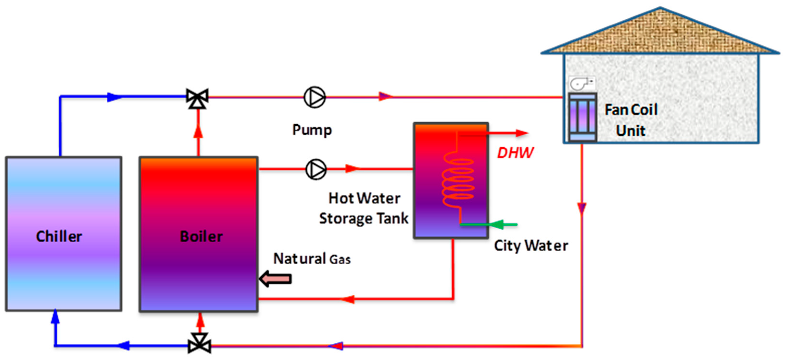
Two systems (cases), with conventional and hybrid renewable microgeneration technologies, were developed and analyzed for residential building applications. Case one is a conventional boiler-chiller system and Case two is the hybrid GAHX-PVT-AWHP trigeneration system. Both systems are able to meet the requirements of a single detached house for its space heating, space cooling and domestic hot water heating.
Through the first case, the residential thermal loads are met with a chiller and boiler system and a fan coil unit as presented in Figure 1. The fan coil unit is located inside the house and a duct system is used to distribute the cooling/heating air. Domestic Hot Water (DHW) tank is installed inside the house and connected to the boiler via pipelines for DHW supply.
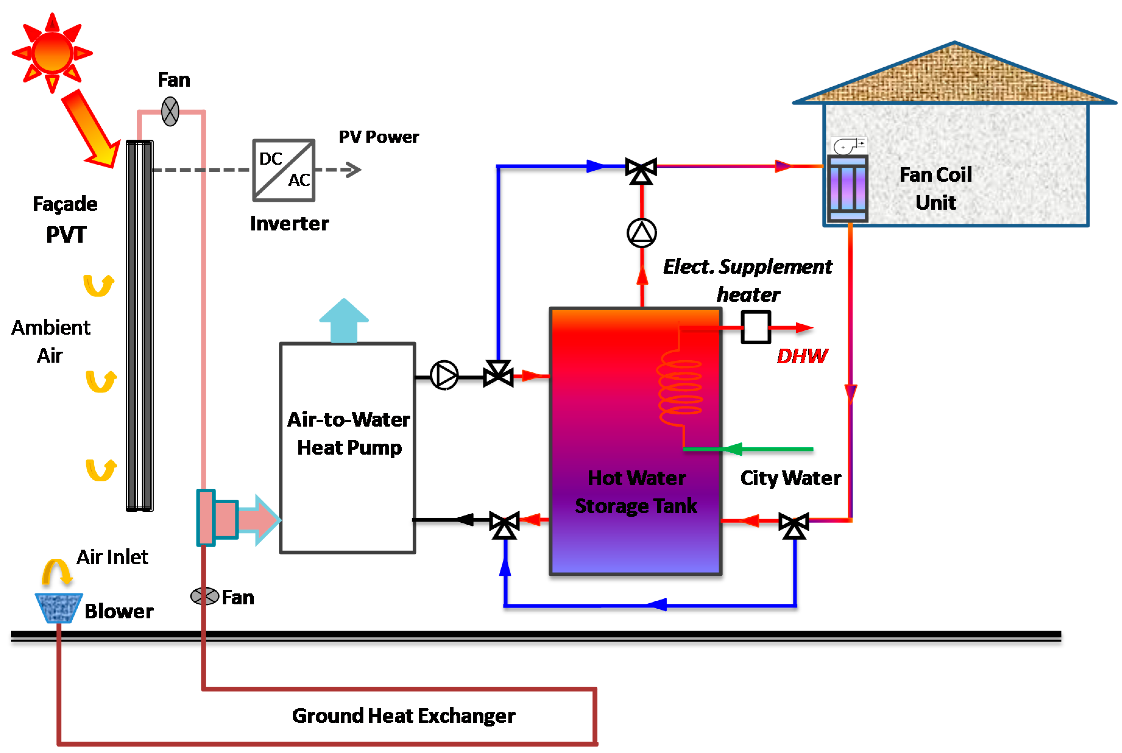
The second case, the renewable trigeneration system as shown in Figure 2, uses an air-to-water heat pump (AWHP) to satisfy the house heating and cooling load demands. The AWHP is integrated with a horizontal ground-to-air heat exchanger (GAHX) and a photovoltaic thermal (PVT) system. The GAHX, sometimes also called earth-tube, utilizes the thermal mass of the soil surrounding to preheat or precool the ambient air before entering to the AWHP, and thereby to increase the efficiency of the heat pump and reduce energy consumption. The PVT panels are built as modules by manufacturers and can generate both electric and thermal energy. The generated electric energy can be used to operate the AWHP both in heating and cooling seasons thereby reducing the electric power import from the grid to the house. The generated thermal energy is used to preheat inlet air to the AWHP in the heating season.
A hot water storage tank is equipped to store energy for house space heating and DHW heating. In summer, the chilled water from the AWHP flows directly to the cooling coil unit without using a cold water storage tank. Three way valves are used to switch between AWHP heating and cooling loops in winter heating and summer cooling seasons, as shown in Figure 2. An electric heater is installed to provide DHW heating in summer, and also in winter to supplement DHW heating in cases where the energy stored in the storage tank is insufficient. The city water has enough pressure to flow the water in the system without using a pump in the DHW loop.

3. Methodology

In order to investigate the performance of the hybrid renewable trigeneration system, energy and environmental analyses were conducted. The methodologies are described in the following sections.

3.1. Energy Analysis Methodology

The energy performance of the trigeneration system was assessed through the primary energy (PE) saving of the investigated case with respect to the reference case (conventional boiler-chiller system). Primary energy is an energy form found in nature that has not been subjected to any conversion or transformation process. Primary energy factor (PEF) is used for calculating energy performance.
The PEF of grid electricity accounts for the energy losses of electricity generation and transport. The electricity PEF factor for Ottawa (Ontario), determined by post-processing electricity generation data for Ontario (2013) published by Environment Canada [49], is 2.46. It agrees with the annual average PEF value found in Ref. [50], which was based on the data from the Independent Electricity System Operator (IESO) [51], a non-for-profit corporate entity responsible for promoting transparency of electricity generation for the Ontario power grid. The PEF of electricity in Korea is 2.75 [52]. Although the primary energy from the grid varies between countries depending on the generating mix in any given year, the average PEF value of Korea and Ontario, 2.6 (an overall efficiency of 39%), is used both for Incheon and Ottawa in the primary energy calculations.
The natural gas PEF is assumed at 1.1 to consider 10% of overhead for delivering to the site [52,53]. It is used to evaluate the primary energy consumption related to the boiler in the reference case. The total primary energy consumption is the sum of primary energy calculated based on the net electricity and natural gas consumption of each case.

3.2. Environmental Analysis Methodology

The environmental performance of each case was evaluated through a simplified approach based on the evaluation of CO2 equivalent emissions. The comparison is based on the avoided CO2 emissions compared to the reference case. The emission factors (EF) used in the analysis for Incheon and Ottawa cases are presented in Table 1.
The natural gas emission factor (EF) used in the calculation is 1888 g/m3 (50.4 kg/GJ or 182 g/kWh) for Ottawa (Ontario), which is obtained from the Environment Canada’s National Inventory Report 1990–2013 Part 2 [54]. For Incheon, the natural gas emission factor of 235 g/kWh [47] is assumed.
The electricity emission factor used in the calculation is 106 g/kWh (29.4 kg/GJ) for Ottawa (Ontario) [55]. This value is calculated based on the three-year average values reported for “Overall Greenhouse Gas Intensity” in the 1990–2012 Canada National Inventory Report (Part 3) [56]. For Incheon, the electricity emission factor of 590 g/kWh [47] is used in the calculations.

4. Simulation Models and Assumptions

4.1. TRNSYS Models

TRNSYS software platform (Version 17.02) [57] is used in the present study to simulate the trigeneration system and the reference conventional system described in the previous section. It is one of the most advanced dynamic building energy simulation programs. TRNSYS library includes a large database of component models (which are called “Type” in TRNSYS) related to buildings, thermal and electrical energy systems, input and output data management and other dependent functions [58]. The components can be connected to form complex systems. In the present study, component models were selected from the TRNSYS libraries and enhanced with latest manufacturers’ systems performance data. Summary of the TRNSYS types used in the simulation and verification of the reference system model was presented in Entchev et al. [32]. Brief descriptions are given to the major components of the trigeneration system, i.e., ground-to-air heat exchanger, PVT panels and air-to-water heat pump in the following.
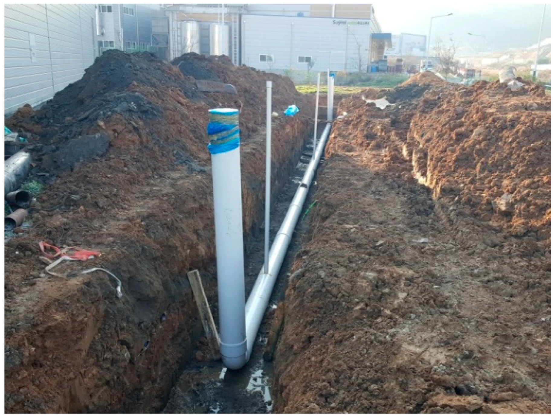
Type 997: multi-level horizontal ground heat exchanger was used to model the ground-to-air heat exchanger. A series of horizontal pipes are buried in the ground to transfer heat from/to the ground. There are different pipe configurations such as parallel, serpentine, double-serpentine and intertwined quadruple serpentine. The impact of the energy storage in the ground is considered where the pipes are surrounded with 3-D rectangular conduction model. An experimental test-rig has been setup in a field in Korea (as shown in Figure 3), and testing data collected at various operating conditions will be used to further validate the TRNSYS GAHX model in the next phase of the study.
The PVT panels were modeled by Type 560: PV/T collector interacting with simple zone models. This model relies on linear factors relating the efficiency of the PV cells to the cell temperature and also the incident solar radiation. Performance data obtained from a manufacturer was used to validate the model. The model outputs (electric/thermal energy and efficiency) are in good agreement with the manufacturer’s data with relative errors within 10%.
The air-to-water heat pump was modeled using TRNSYS Type 941. It is not a first principles model, but relies instead upon catalogue data readily available from heat pump manufacturers. The component requires two data files, one for cooling performance and another for heating performance. Both data files provide capacity and power draw of the heat pump as a function of entering water temperature and entering air temperature to the heat pump.

4.2. House Specifications and Thermal Loads

The hybrid trigeneration system is assumed to serve a one-story residential house with a floor area of 200 m2 and a height of 2.7 m. The building specifications meet the building envelope requirements for climate zone 4 recommended by ASHRAE Standard 90.1–2007 [59].
Space heating and cooling loads are dependent on the house geographic location, building envelope and room thermostat set-point. These loads will be presented later in the results section. The house domestic hot water profile is based on the Canadian Centre for Housing Technology (CCHT) [60] simulated DHW-draw profile and average hot water usage value (252 L/day) recommended by ASHRAE [59] for “typical” families. The DHW consumption for the house used in the present study is 255 L/day with 7 draws. Usually the DHW usage pattern is different in weekdays and weekends, however, the same profile is used in the simulation for simplicity.

4.3. Equipment Capacity and Specifications

In the reference case, the boiler is a high-performance condensing boiler with a capacity of 30 kW for Ottawa case and 25 kW for Incheon case. The boilers have a steady state efficiency of 94%. The chiller has a capacity of 3-ton for Ottawa case and 4-ton for Incheon case, and a rated coefficient of performance (COP) of 3 under testing conditions (entering water temperature 7 °C and ambient air temperature 35 °C). The hot water tank for DHW storage has a volume of 190 L (50 US gallons).
For the trigeneration system, the ground-to-air heat exchanger is assumed to have a total length of 250 m with tube inner diameter of 0.25 m. The tube is buried at 2 m deep in serpentine configuration. There are 10 PVT panels installed vertically on south-facing façade. Two PVT panels are connected in series, which forms 5 parallel rows. Each PVT panel has a rated electric capacity of 295 W and thermal capacity of 1535 W. The air-to-water heat pump has a rated heating capacity of 9 kW with a COP of 3.3 under testing conditions (entering air temperature 7 °C and water temperature 40 °C), and a rated cooling capacity of 8 kW with a COP of 2.8 under testing conditions (entering air temperature 35 °C and water temperature 12 °C). The storage tank volume is 1000 m3.

4.4. Control Approaches

The room temperature is controlled based on the schedule presented in Table 2 for heating and cooling season respectively.
The control strategies for the reference system and the trigeneration system are shown in Table 3 and Table 4 respectively.
For the reference system, the boiler is turned on when there is a call-for-heat signal either from the room thermostats or the DHW storage tank aquastat. The boiler outlet temperature is controlled at 82 ± 2 °C and a tempering valve reduces the hot water temperature supplied to the heating coils down to 60 °C. The temperature in the domestic hot water storage tank is controlled by two separate temperature nodes (T2 is located in the second tank node that is near the tank top and T5 located in the middle of the tank) as shown in Table 3. Whereas the chiller on/off is controlled by the room thermostat set-points in the cooling season and the chilled water temperature is kept at 7 ± 2 °C.
The air-to-water heat pump operation in the trigeneration system (Case 2) is controlled by the aquastat (s) near the bottom (T8) of the hot water tank as shown in Table 4. The AWHP is turned on when T8 ≤ 40 °C and turned off until T8 ≥ 45 °C. Since the aquastat T8 is located at the bottom of the storage tank, the temperature at the tank top is expected to be typically in the range between 45 and 50 °C.
The ambient air is generally preheated by the ground-to-air heat exchanger before entering the AWHP in the heating period. However, if the average air temperature inside the PVT panels is 5 °C higher than the air near the outlet of the earth tube, the preheated air from the PVT is drawn to the AWHP until the temperature difference is less than 2 °C. In cooling season, the ambient air is precooled by the GAHX before entering the AWHP.
The electric heater for DHW heating is turned on when the DHW temperature from the hot water storage tank is less than 49 °C. It should be noted that the DHW heating is solely provided by the electric heater in the summer as the AWHP is in cooling mode.

4.5. Weather Data and Simulation Period

The system performance is not only depending on its configuration, but also depending on its geographic location, which affects space heating/cooling load profiles. As mentioned earlier, two cities were chosen for evaluating the performance of the proposed trigeneration system: Incheon, Korea and Ottawa, Canada. The weather data source for Ottawa is Canadian Weather for Energy Calculations (CWEC) database, and for Incheon is International Weather for Energy Calculations (IWEC) database. Both sets of weather data were downloaded from EnergyPlus website [61] in EnergyPlus format.
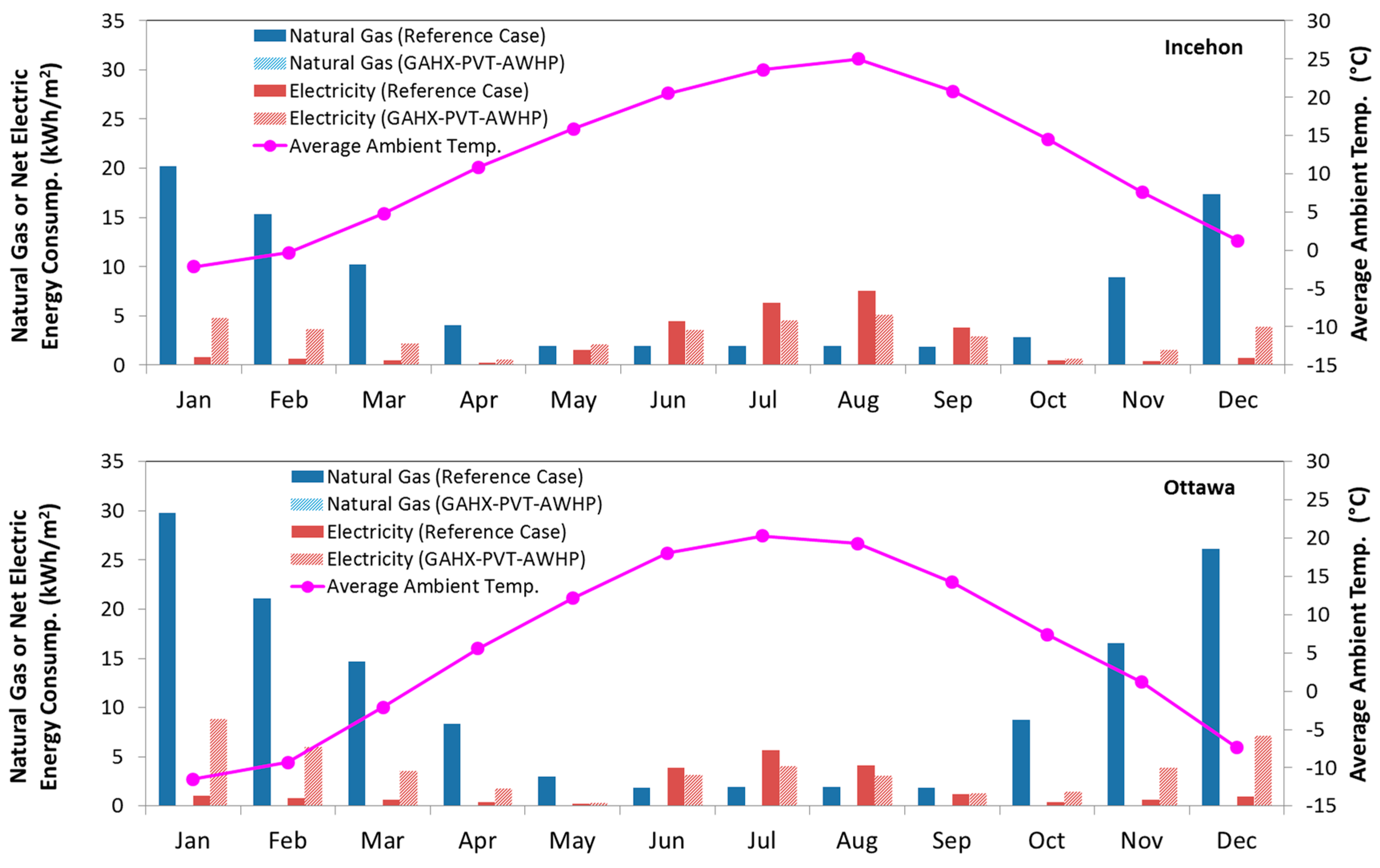
In Incheon, the warmest month is in August with a daily average of 25.2 °C and the coolest month is January with a daily average of −2.1 °C. The annual average temperature is 12.1 °C. In Ottawa, the warmest month is in July with a daily average of 20.5 °C and the coolest month is January with a daily average of −11.5 °C. The annual average temperature is 6.3 °C.
For Incheon, the heating season is assumed to start from mid-October to April with the cooling season from the beginning of May to mid-October. However, for Ottawa, the cooling season is slightly shorter, starting from June to end of September due to its relatively cool summer compared to Incheon.

5. Results and Discussion

5.1. Thermal Loads

Table 5 presents the annual space heating, space cooling and DHW load intensity (kWh/m2·year) for the two simulated cases under Incheon and Ottawa weather. The total floor area of the house is 200 m2.
The annually total thermal load intensity is approximately 122 kWh/m2·year (88 GJ/year) in Incheon and 156 kWh/m2·year (112 GJ/year) in Ottawa. The total load intensity in Incheon is 22% lower than the total thermal load of Ottawa. While the DHW load is the same for Ottawa and Incheon, the space heating load in Incheon is 43% lower than that of in Ottawa due to mild winter climate. On the other hand, the space cooling load in Incheon is 56% higher than that of in Ottawa due to a relatively warm summer. The difference between the space heating and cooling loads in Incheon is much smaller compared to Ottawa where is highly heating dominated.

5.2. Electricity and Natural Gas Consumption

Figure 4 illustrates the annual natural gas and HVAC (heating, ventilation, and air conditioning) electricity intensities as well as system electricity production intensity for the two cases in Incheon and Ottawa respectively. For Case 2, the GAHX-PVT-AWHP trigeneration system, the PVT electricity production is shown in negative value as illustrated in Figure 4. Furthermore, monthly natural gas and net electric energy consumption for the two investigated cases are shown in Figure 5.
Compared to the reference boiler-chiller system (Case 1), the trigeneration system has no natural gas consumption, but has much higher annual HVAC electricity consumption due to the introduction of the electricity-driven air-to-water heat pump for space heating/cooling and the supplementary electric heater for DHW heating. However, it is noted that the electricity consumption of the trigeneration system in summer cooling months is lower than that of the reference case (c.f., Figure 5). This is mainly because precool the entering air to the AWHP using the ground-to-air heat exchanger improves the heat pump efficiency and results low energy consumption.
The results from the Ottawa cases indicate the same trends as that shown in the Incheon cases, but with higher overall energy consumption intensities due to high thermal loads in Ottawa. On the other hand, the PVT production in Ottawa is higher than that of in Incheon due to higher solar radiation in Ottawa.

5.3. Primary Energy Consumption

Figure 6 presents the net primary energy consumption intensities in heating and cooling periods for Ottawa and Incheon respectively. The results show that the trigeneration system (Case 2), with the introduction of the renewable components: GAHX and PVT panels, achieves lower primary energy consumption in comparison to the Reference case, the boiler-chiller system (Case 1). The primary energy consumption intensity is reduced to 92.5 kWh/m2·year from 168.3 kWh/m2·year in Incheon and is reduced to 115.7 kWh/m2·year from 201.3 kWh/m2·year in Ottawa.
The fraction of the primary energy consumed by different components is illustrated in Figure 7 for Incheon and Ottawa respectively.
For the conventional boiler-chiller system, the results indicate that the primary energy consumption by the boiler accounts for the largest share (58% for Incheon and 74% for Ottawa), followed by the chiller (32% for Incheon and 16% for Ottawa), blower fans for the air handlers (~8%) and then the circulation pumps (~2%).
For the GAHX-PVT-AWHP trigeneration system, the primary energy consumed by the air-to-water heat pump accounts for the largest share (53% for Incheon and 60% for Ottawa), followed by the electric heater for DHW heating (27% for Incheon and 18% for Ottawa). The blower fans for the earth-tube, PVT and air handler take for approximately 16% of the shares, both for Incheon and Ottawa cases. The primary energy consumption by the circulation pumps is close to 4% in Incheon and slightly higher in Ottawa at 5%.
It is observed that the electric heater for DHW heating in the trigeneration system takes a significant share of the primary energy consumption. Further investigation will be conducted in the next phase of the study to seek a solution for reducing the energy consumption by DHW heating, for example using a heat pump with DHW heating capacity rather than using an electric heater.

5.4. Overall Primary Energy Savings

The primary energy consumption of the GAHX-PVT-AWHP trigeneration system (Case 2) is compared to the conventional boiler-chiller system (Case 1) and shown in Figure 8. Due to the use of heat pump and the contribution of solar and geothermal energy, the GSHX-PVT-AWHP trigeneration system achieves significant primary energy saving. The results indicate that the energy saving in Incheon is slightly higher than that of in Ottawa both in heating and cooling periods. The annual overall primary energy saving is 45% in Incheon and 42.5% in Ottawa.

5.5. Overall System Performance

The system performance is calculated and presented in COP values (due to the use of chiller and AWHP) in Table 6 for Ottawa and Incheon cases respectively. The system COP, either in heating period or cooling period or annual, is the ratio of the total energy delivered to the buildings (which includes space heating, space cooling and DHW energy as well as electricity production if any) to the total consumed energy (natural gas and electricity) in the respective period.
The results in Table 6 show that Case 2 (GAHX-PVT-AWHP trigeneration system) has much higher COP in comparison to the conventional boiler-chiller system (Case 1), for both Ottawa and Incheon. The overall system COP is approximately 1.0 for the conventional system and is around 2.9 for the trigeneration system. This is again because the trigeneration system uses heat pump which efficiency (COP is in the range of 1.5–4) is much higher than that of the conventional boiler (<95%). Further the electricity generated by the PVT panels is directly used for the system operation which significantly reduces the amount of electricity required from the grid. In addition, utilization of earth-tube and PVT for preheating or precooling air incoming to the AWHP improves the heat pump’s efficiency (COP).

5.6. Greenhouse Gas Emission

Figure 9 shows the annual CO2 equivalent emission intensity resulted from the grid electricity and natural gas for the two investigated systems in Incheon and Ottawa respectively.
The results show that the total annual emission from systems in Incheon is 36.9 kg/m2·year for the conventional boiler-chiller case and reduced to 21 kg/m2·year for the hybrid renewable trigeneration system. For Ottawa case, the annual emission intensity is reduced from 26.8 kg/m2·year for the conventional system to 4.7 kg/m2·year for the trigeneration system. It can be seen from Figure 9 that the emission from the systems in Ottawa is much lower than those in Incheon due to a significant share of nuclear power (>50% [49,50,51]) in the grid electricity mix in Ontario. The CO2 emission reduction resulted from the renewable trigeneration system is significant, standing at 43% in Incheon and 82% in Ottawa.

6. Conclusions

In the present study, two systems (cases) with conventional and hybrid renewable trigeneration technologies respectively, were developed and analyzed for applications in residential buildings. The conventional system (Case 1) utilizes a boiler for space and domestic hot water heating and a chiller for space cooling. The renewable trigeneration system (Case 2) is equipped with an air-to-water heat pump which is integrated with a ground-to-air heat exchanger and building integrated PVT panels for preheating/precooling the incoming air and for electricity production. It is operated utilizing electricity only (from the PVTs and the grid), which leads to CO2 free system operation on site. The two systems were analyzed under Incheon (Republic of Korea) and Ottawa (Canada) weather conditions. The full year simulation of both systems led to a better understanding of: the components’ contribution to overall energy savings, optimal sizing, integration and control. The results showed that the trigeneration system achieves lower primary energy consumption and CO2 emission in comparison to the reference boiler-chiller system, mainly due to the introduction of significant renewable components. The annual primary energy saving is 45% in Incheon and is 42% in Ottawa. The CO2eq emission reduction resulted from the renewable trigeneration system is also significant, standing at 43% in Incheon and 82% in Ottawa. The achieved emission and energy reductions by the proposed renewable system showed that its implementation at a residential level can successfully contribute to “decarbonisation” of the grid and to support Government goals in saving energy and reducing GHG emissions.
The renewable trigeneration system reduces the buildings’ dependency on the electricity grid which fits well with the Smart Grid concept and with utilities various load shaving and load leveling strategies. Its capability to generate electricity and thermal energy at the point of use is considered more attractive for inclusion in the future Smart Energy Network applications where the centralized old “one-to-many” approach to supply energy will be replaced by “many-to-many” concept [62,63]. The trigeneration systems will provide autonomous operation and supply of energy to homes/buildings with provision to be optimally managed and integrated within the micro-grids or “virtual utility” through ICT technologies and Big Data Analytics (BDA).

7. Future Work

The proposed trigeneration system will be built, tested and evaluated under real life conditions in a test facility in Korea. The results from the present simulation study facilitate the development of the testing rig and the subsequent experimental procedures. The data to be obtained from the field testing will be used to further validate the TRNSYS component models and the integrated system model for improved accuracy. Thereafter, the application of the GAHX-PVT-AWHP trigeneration system in small community scale with mixed residential and commercial buildings will be investigated. Life-cycle economic analysis will be conducted as well to thoroughly evaluate the overall performance of the trigeneration system.

Acknowledgments

This research was supported by a grant (#15CTAP-C096424-01) from Technology Advancement Research Program (TARP) funded by Ministry of Land, Infrastructure and Transport of the Korean government. Funding for this work was also provided by Natural Resources Canada through the Program of Energy Research and Development (PERD).

Author Contributions

Euy-Joon Lee, Evgueniy Entchev and Eun-Chul Kang conceived the research ideas and the trigeneration technologies for investigation. Eun-Chul Kang, Nam-Jin Lyu and Kwang-Seob Lee developed system configurations, operational control strategies, and testing facility setups. Libing Yang and Mohamed Ghorab developed TRNSYS models for simulation study and conducted data analyses. All authors have contributed to the writing, editing and revising of the manuscript.

Conflicts of Interest

The authors declare no conflict of interest. The founding sponsors had no role in the design of the study; in the collection, analyses, or interpretation of data; in the writing of the manuscript, and in the decision to publish the results.

References

  1. European Parliament; Council of the European Union. Directive 2004/8/EC of the European Parliament and of the Council of the 11 February 2004 on the promotion of cogeneration based on the useful heat demand in the internal energy market and amending Directive 92/42/EEC. Off. J. Eur. Union 2004, 47, 50–60. [Google Scholar]
  2. Maghanki, M.M.; Ghobadian, B.; Najafi, G.; Galogah, R.J. Micro combined heat and power (MCHP) technologies and applications. Renew. Sustain. Energy Rev. 2013, 28, 510–524. [Google Scholar] [CrossRef]
  3. Evangelisti, S.; Lettieri, P.; Clift, R.; Borello, D. Distributed generation by energy from waste technology: A life cycle perspective. Process Saf. Environ. Prot. 2015, 93, 161–172. [Google Scholar] [CrossRef]
  4. Angrisani, G.; Roselli, C.; Sasso, M. Distributed microtrigeneration systems. Prog. Energy Combust. Sci. 2012, 38, 502–521. [Google Scholar] [CrossRef]
  5. Sonar, D.; Soni, S.L.; Sharma, D. Micro-trigeneration for energy sustainability: Technologies, tools and trends. Appl. Therm. Eng. 2014, 71, 790–796. [Google Scholar] [CrossRef]
  6. Barbieri, E.; Spina, P.; Venturini, M. Analysis of innovative micro-CHP systems to meet household energy demands. Appl. Energy 2012, 97, 723–733. [Google Scholar] [CrossRef]
  7. Moghaddam, A.A.; Seifi, A.; Niknam, T.; Pahlavani, M.R.A. Multi-objective operation management of a renewable MG (micro-grid) with back-up micro-turbine/fuel cell/battery hybrid power source. Energy 2011, 36, 6490–6507. [Google Scholar] [CrossRef]
  8. Shaneb, O.; Coates, G.; Taylor, P. Sizing of residential μCHP systems. Energy Build. 2011, 43, 1991–2001. [Google Scholar] [CrossRef]
  9. Kim, J.; Cho, W.; Lee, K. Optimum generation capacities of micro combined heat and power systems in apartment complexes with varying numbers of apartment units. Energy 2012, 35, 5121–5131. [Google Scholar] [CrossRef]
  10. Dorer, V.; Weber, A. Energy and CO2 emissions performance assessment of residential micro-generation systems with dynamic whole-building simulation programs. Energy Convers. Manag. 2009, 50, 648–657. [Google Scholar] [CrossRef]
  11. Gusdorf, J.; Douglas, M.; Swinton, M.; Szadkowski, F.; Manning, M. Testing a residential system including combined heat and power and ground heat source heat pumps at the Canadian Centre for Housing Technology. In Proceedings of the 1st International Conference on Microgeneration and Related Technologies, Ottawa, ON, Canada, 10–14 March 2008.
  12. Yang, L.; Douglas, M.A.; Gusdorf, J.; Szadkowski, F.; Limouse, E.; Manning, M.; Swinton, M. Residential total energy system testing at the Canadian Center for Housing Technology. In Proceedings of the ASME 2007 Power Conference, San Antonio, TX, USA, 17–19 July 2007.
  13. Smith, M.; Few, P. Domestic-scale combined heat-and-power system incorporating a heat pump: Analysis of a prototype plant. Appl. Energy 2011, 70, 215–232. [Google Scholar] [CrossRef]
  14. Tempesti, D.; Manfrida, G.; Fiaschi, D. Thermodynamic analysis of two micro CHP systems operating with geothermal and solar energy. Appl. Energy 2012, 97, 609–617. [Google Scholar] [CrossRef]
  15. Guo, T.; Wang, H.; Zhang, S. Selection of working fluids for a novel low temperature geothermally-powered ORC based cogeneration system. Energy Convers. Manag. 2011, 52, 2384–2391. [Google Scholar] [CrossRef]
  16. Ribberink, H.; Lombardi, K.; Yang, L.; Entchev, E. Hybrid renewable-microgeneration energy system for power and thermal generation with reduced emissions. In Proceedings of the 2nd International Conference on Microgeneration and Related Technologies, Glasgow, UK, 1–3 April 2011.
  17. Hawkes, A.; Leach, M. Cost-effective operating strategy for residential micro-combined heat and power. Energy 2007, 32, 711–723. [Google Scholar] [CrossRef]
  18. Entchev, E.; Gusdorf, J.; Swinton, M.; Bell, M.; Szadkowski, F.; Kalbfleisch, W.; Marchand, R. Micro-generation technology assessment for housing technology. Energy Build. 2004, 36, 925–931. [Google Scholar] [CrossRef]
  19. Hamada, Y.; Takeda, K.; Goto, R.; Kubota, H. Hybrid utilization of renewable energy and fuel cells for residential energy systems. Energy Build. 2011, 43, 3680–3684. [Google Scholar] [CrossRef]
  20. International Energy Agency, Energy Conversion in Buildings and Community System Program (ECBCS). Annex 42 The Simulation of Building-Integrated Fuel Cell and Other Cogeneration Systems (COGEN-SIM). Available online: http://www.ecbcs.org/annexes/annex42.htm (accessed on 12 September 2016).
  21. Barelli, L.; Bidini, G.; Gallorini, F.; Ottaviano, A. Dynamic analysis of PEMFC-based CHP systems for domestic application. Appl. Energy 2012, 91, 13–28. [Google Scholar] [CrossRef]
  22. Calise, F.; Ferruzzi, G.; Vanoli, L. Transient simulation of polygeneration systems based on PEM fuel cells and solar heating and cooling technologies. Energy 2012, 41, 18–30. [Google Scholar] [CrossRef]
  23. Bang-Møller, C.; Rokni, M.; Elmegaard, B. Exergy analysis and optimization of a biomass gasification, solid oxide fuel cell and micro gas turbine hybrid system. Energy 2011, 36, 4740–4752. [Google Scholar] [CrossRef]
  24. Liso, V.; Olesen, A.C.; Nielsen, M.; Kær, S.K. Performance comparison between partial oxidation and methane steam reforming processes for solid oxide fuel cell (SOFC) micro combined heat and power (CHP) system. Energy 2011, 36, 4216–4226. [Google Scholar] [CrossRef]
  25. Thorsteinson, E. Performance testing of a 1 kWe PEM fuel cell cogeneration system. In Proceedings of the 2nd International Conference on Microgeneration and Related Technologies, Glasgow, Scotland, UK, 1–3 April 2011.
  26. Obara, S.; Watanabe, S.; Rengarajan, B. Operation method study based on the energy balance of an independent microgrid using solar-powered water electrolyzer and an electric heat pump. Energy 2011, 36, 5200–5213. [Google Scholar] [CrossRef]
  27. Bayer, P.; Saner, D.; Bolay, S.; Rybach, L.; Blum, P. Greenhouse gas emission savings of ground source heat pump systems in Europe: A review. Renew. Sustain. Energy Rev. 2012, 16, 1256–1267. [Google Scholar] [CrossRef]
  28. Self, S.J.; Reddy, B.V.; Rosen, M.A. Geothermal heat pump systems: Status review and comparison with other heating options. Appl. Energy 2013, 101, 341–348. [Google Scholar] [CrossRef]
  29. Omer, A.M. Ground-source heat pumps systems and applications. Renew. Sustain. Energy Rev. 2008, 12, 344–371. [Google Scholar] [CrossRef]
  30. Sarbu, I.; Sebarchievici, C. General review of ground-source heat pump systems for heating and cooling of buildings. Energy Build. 2014, 70, 441–454. [Google Scholar] [CrossRef]
  31. Lee, E.; Putrayudha, A.; Kang, E.; Cuha, I. Optimizing GSHP Performance with ICT and RETScreen Plus. J. Energy Power Eng. 2014, 8, 677–681. [Google Scholar]
  32. Entchev, E.; Yang, L.; Ghorab, M.; Lee, E.J. Simulation of hybrid renewable microgeneration systems in load sharing applications. Energy 2013, 50, 252–261. [Google Scholar] [CrossRef]
  33. Entchev, E.; Yang, L.; Ghorab, M.; Lee, E.J. Performance analysis of a hybrid renewable microgeneration system in load sharing applications. Appl. Therm. Eng. 2014, 71, 697–704. [Google Scholar] [CrossRef]
  34. Caneli, M.; Entchev, E. Dynamic simulations of hybrid energy systems in load sharing application. Appl. Therm. Eng. 2015, 78, 315–325. [Google Scholar] [CrossRef]
  35. Putrayudha, S.A.; Kang, E.C. A study of photovoltaic/thermal (PVT)—Ground source heat pump hybrid system by using fuzzy logic control. Appl. Therm. Eng. 2015, 89, 578–586. [Google Scholar] [CrossRef]
  36. Zuo, J.; Zhao, Z. Green building research—Current status and future agenda: A review. Renew. Sustain. Energy Rev. 2014, 30, 271–281. [Google Scholar] [CrossRef]
  37. Suresh, K.S.; Mukesh, P.; Vishvendra, N.B. Ground coupled heat exchangers: A review and applications. Renew. Sustain. Energy Rev. 2015, 47, 83–92. [Google Scholar]
  38. REHAU Manual. Ground-Air Heat Exchanger System. Available online: https://www.rehau.com/gb-en/building-technology/renewable-energy/ground-air-heat-exchangers (accessed on 12 September 2016).
  39. Feist, W.; Schnieders, J.; Dorer, V.; Haas, A. Re-inventing air heating: convenient and comfortable within the frame of the passive house concept. Energy Build. 2005, 37, 1186–1203. [Google Scholar] [CrossRef]
  40. Energy-Efficient Buildings: Heating and Cooling Equipment; International Energy Agency: Paris, France, 2011.
  41. Ascione, F.; Bellia, L.; Minichiello, F. Earth to air heat exchangers for Italian climates. Renew. Energy 2011, 36, 2177–2188. [Google Scholar] [CrossRef]
  42. Chel, A.; Janssens, A.; Michel, D.P. Thermal performance of a nearly zero energy passive house integrated with the air-air heat exchanger and the earth-water heat exchanger. Energy Build. 2015, 96, 53–63. [Google Scholar] [CrossRef]
  43. Murphy, M. LECO Simulating Earth to Air Heat Exchangers; Project Report 70; SINTEF Building and Infrastructure: Oslo, Norway, 2011. [Google Scholar]
  44. Kumar, A.; Baredar, P.; Qureshi, U. Historical and recent development of photovoltaic thermal (PVT) technologies. Renew. Sustain. Energy Rev. 2015, 42, 1428–1436. [Google Scholar] [CrossRef]
  45. Chow, T.T. A review on photovoltaic/thermal hybrid solar technology. Appl. Energy 2010, 87, 365–379. [Google Scholar] [CrossRef]
  46. International Energy Agency, Energy Conversion in Buildings and Communities System Programme (EBC). Annex 54 Analysis of Micro-Generation & Related Energy Technologies in Buildings. Available online: http://www.ecbcs.org/annexes/annex54.htm (accessed on 12 September 2016).
  47. IEA/EBC Annex 54 Team. Impact of Support Mechanisms on Microgeneration Performance. IEA Publication, Energy in Buildings and Communities (EBC), Annex 54. 2014. Available online: http://www.iea-ebc.org/projects/completed-projects/ebc-annex-54/ (accessed on 12 September 2016).
  48. IEA/EBC Annex 54 Team. A Comparative Review of Microgeneration Policy Instruments in OECD Countries. IEA publication, Energy in Buildings and Communities (EBC), Annex 54. 2014. Available online: http://www.iea-ebc.org/projects/completed-projects/ebc-annex-54/ (accessed on 12 September 2016).
  49. Environment Canada. National Inventory Report 1990–2013, Part 3. Environment Canada, 2015. Available online: http://unfccc.int/national_reports/annex_i_ghg_inventories/national_inventories_submissions/items/7383.php (accessed on 12 September 2016).
  50. Bucking, S.; Dermardiros, V.; Athienitis, A. The effect of hourly primary energy factors on optimal net-zero energy building design. In Proceedings of the eSim 2016, Hamilton, ON, Canada, 3–6 May 2016.
  51. Independent Electricity System Operator (IESO). Available online: http://www.ieso.ca (accessed on 12 September 2016).
  52. Park, D.J.; Yu, K.H.; Yoon, Y.S.; Kim, K.H.; Kim, S.S. Analysis of a building energy efficiency certification system in Korea. Sustainability 2015, 7, 16086–16107. [Google Scholar] [CrossRef]
  53. Sustainable Energy Authority of Ireland (seai). Available online: http://www.seai.ie (accessed on 12 September 2016).
  54. Environment Canada. National Inventory Report 1990–2013, Part 2, Environment Canada. 2015. Available online: http://unfccc.int/national_reports/annex_i_ghg_inventories/national_inventories_submissions/items/7383.php (accessed on 12 September 2016).
  55. Ministry of Environment. 2014 B.C. Best Practices Methodology for Quantifying Greenhouse Gas Emissions; Ministry of Environment: Victoria, BC, Canada, November 2014.
  56. Environment Canada. National Inventory Report 1990–2012, Part 3. Environment Canada, 2014. Available online: http://unfccc.int/national_reports/annex_i_ghg_inventories/national_inventories_submissions/items/7383.php (accessed on 12 September 2016).
  57. TEES Company (TRNSYS Website). Available online: http://www.trnsys.com/ (accessed on 12 September 2016).
  58. University of Wisconsin-Madison. TRNSYS 17—Mathematical Reference. Volume 4. Available online: http://web.mit.edu/parmstr/Public/TRNSYS/04-MathematicalReference.pdf (accessed on 12 September 2016).
  59. ASHRAE Standard 90.1–2007; American Society of Heating and Air-Conditioning Engineers, Inc.: Atlanta, GA, USA, 2007.
  60. Canadian Centre for Housing Technology. Available online: http://www.ccht-cctr.gc.ca/eng/index.html (accessed on 12 September 2016).
  61. EnergyPlus. Weather Data, EnergyPlus Energy Simulation Software. Available online: http://apps1.eere.energy.gov/buildings/energyplus/ (accessed on 12 September 2016).
  62. Entchev, E. Smart Energy Networks—A Transition towards Future Sustainable, Intelligent and Cost Effective Energy System; Smart Energy Networks Leadership Forum: Toronto, ON, Canada, 2013. [Google Scholar]
  63. Yang, L.; Entchev, E. Smart Energy Networks with Big Data Analytics. In Proceedings of the Microgen IV International Conference, Tokyo, Japan, 28–30 October 2015.
Figure 1. Schematic diagram of conventional system (Case 1).
Energies 09 00760 g001
Figure 2. Schematic diagram of trigeneration system with integration of air-to-water heat pump, photovoltaic thermal panels and ground-to-air heat exchanger (Case 2).
Energies 09 00760 g002
Figure 3. Ground-to-air heat exchanger field test-rig.
Energies 09 00760 g003
Figure 4. Annual electricity and natural gas energy consumption/production intensity.
Energies 09 00760 g004
Figure 5. Monthly natural gas and net electrical energy consumption intensity.
Energies 09 00760 g005
Figure 6. Annual primary energy consumption intensity.
Energies 09 00760 g006
Figure 7. Distribution of primary energy consumption by components.
Energies 09 00760 g007
Figure 8. Overall primary energy saving of GAHX-PVT-AWHP trigeneration system.
Energies 09 00760 g008
Figure 9. Annual CO2 equivalent emission intensity.
Energies 09 00760 g009
Table 1. CO2 emission factors used in case studies.
Emission Factor (CO2eq g/kWh)IncheonOttawa
Natural Gas235182
Grid Electricity590106
Table 2. Room thermostat set-points.
HeatingCooling
Time period of dayThermostat set-pointTime period of dayThermostat set-point
6:00–9:00, 16:00–22:0021 °C9:00–16:0026 °C
0:00–6:00, 9:00–16:00, 22:00–24:0018 °C0:00–9:00, 16:00–24:0024 °C
Table 3. Control strategies for boiler-chiller system (reference case).
Case 1BoilerChiller
ONOFFONOFF
Heating PeriodTroom ≤ Tset − 0.5 °C and/or T2 a ≤ 46 °CTroom ≥ Tset + 0.5 °C and/or T5 a ≥ 49 °CNANA
Cooling PeriodT2 ≤ 46 °CT5 ≥ 49 °CTroom ≥ Tset + 0.5 °CTroom ≤ Tset − 0.5 °C
a T2, and T5 are the temperature sensors in storage tank node 2 and 5 respectively. Each storage tank is divided into 10 isothermal nodes: 1 at the tank top and 10 at the tank bottom.
Table 4. Control strategies for trigeneration system with integration of air-to-water heat pump, photovoltaic thermal panels and ground-to-air heat exchanger (Case 2).
Case 2AWHPHP Inlet Air Preheating in PVT Mode aAux. Heater for DHW Heating
ONOFFONOFFONOFF
Heating PeriodT8 b ≤ 40 °CT8 b ≥ 45 °CTpvt − TGAHX ≥ 5 °CTpvt − TGHAX ≤ 2 °CTdhw < 49 °CTdhw ≥ 49 °C
Cooling PeriodTroom ≤ Tset − 0.5 °CTroom ≥ Tset + 0.5 °CNA cNA cNANA
a In heating period, air preheating is in earth-tube mode if it is not in PVT preheating mode; b T8 is the temperature sensor in storage tank node 8. Each storage tank is divided into 10 isothermal nodes: 1 at the tank top and 10 at the tank bottom; c In cooling period, air precooling is in earth-tube mode.
Table 5. Annual space heating, space cooling and domestic hot water load intensity.
Thermal Load Intensity (kWh/m2)IncheonOttawa
Space heating63.6111.0
Space cooling36.623.4
DHW21.421.4
Table 6. Overall system performance (COP).
CityIncheonOttawa
PeriodCase 1 Boiler-ChillerCase 2 GAHX-PVT-AWHPCase 1 Boiler-ChillerCase 2 GAHX-PVT-AWHP
Heating Period0.933.100.943.27
Cooling Period1.452.521.482.27
Annual Overall1.042.871.002.89

