
Potential of Reversible Solid Oxide Cells as Electricity Storage System


Department of Energy, Systems, Territory and Constructions Engineering, University of Pisa, Largo Lucio Lazzarino, Pisa 56122, Italy
*
Author to whom correspondence should be addressed.
†
These authors contributed equally to this work.
Energies 2016, 9(8), 662; https://doi.org/10.3390/en9080662
Submission received: 23 June 2016
/
Revised: 4 August 2016
/
Accepted: 15 August 2016
/
Published: 19 August 2016
(This article belongs to the Special Issue Solid Oxide Fuel Cells)
Abstract
:Electrical energy storage (EES) systems allow shifting the time of electric power generation from that of consumption, and they are expected to play a major role in future electric grids where the share of intermittent renewable energy systems (RES), and especially solar and wind power plants, is planned to increase. No commercially available technology complies with all the required specifications for an efficient and reliable EES system. Reversible solid oxide cells (ReSOC) working in both fuel cell and electrolysis modes could be a cost effective and highly efficient EES, but are not yet ready for the market. In fact, using the system in fuel cell mode produces high temperature heat that can be recovered during electrolysis, when a heat source is necessary. Before ReSOCs can be used as EES systems, many problems have to be solved. This paper presents a new ReSOC concept, where the thermal energy produced during fuel cell mode is stored as sensible or latent heat, respectively, in a high density and high specific heat material and in a phase change material (PCM) and used during electrolysis operation. The study of two different storage concepts is performed using a lumped parameters ReSOC stack model coupled with a suitable balance of plant. The optimal roundtrip efficiency calculated for both of the configurations studied is not far from 70% and results from a trade-off between the stack roundtrip efficiency and the energy consumed by the auxiliary power systems.

1. Introduction
The share of renewable energy in the electricity generation mix has been increasing for many years in order to reduce the dependency on fossil fuels and mitigate carbon dioxide emissions. This trend is having a strong impact on the electric energy system: in the last 60 years, electric grids have been built and managed so that the electric energy produced by a small number of large power plants could be dispatched to satisfy the demand of a large number of users. In this scenario, it was quite easy to predict the simultaneity of large numbers of small loads by statistical methods, thus controlling the power output of large power plants in a centralized control room.
Nowadays, the number of small size renewable power plants with a much smaller power output is increasing and is given the priority to dispatch the generated power, by creating significant challenges in keeping the electric grids balanced. This is especially true in smaller or more isolated sections of the electric grids with a large share of intermittent renewable energy systems (RES). Therefore, it is necessary to develop solutions that could provide a storage capacity, in order to improve the matching of the demand and supply of electricity. The development of a large storage capacity is the key challenge that must be faced to reduce the stress on the grid, and to increase the share of renewable energy beyond the current level [1].
Pumped hydro storage represents about 95% of worldwide electrical energy storage (EES), but it is close to the full available capacity [2]. Other solutions (e.g., compressed air energy storage) were mostly discontinued after testing in some pilot installations, due to a relatively low efficiency and location restrictions. New generation batteries (e.g., lithium ion, redox flow) provide good efficiency, but they are still not able to meet the requirements for a durable and cost-effective EES [3]. Furthermore, because a range of applications, and thus operating requirements, are expected from EES devices, a portfolio of different technology solutions will be beneficial [1].
The direct production of hydrogen by reverting the operation of fuel cells has been studied for decades as a means to store electric energy, and, most recently, the interest has increased by focusing on the use of high temperature solid oxide cells for electrolysis. A fuel cell is an electrochemical conversion device that produces electrical power directly from the chemical energy stored in some fuel species. In electrolysis, the cell operates by reducing chemical species and producing a fuel, while consuming electric energy.
In the literature, various authors have been interested in the simulation of the interaction between hydrogen based energy storage technologies and the electric grid. Kasai [4] discussed the hydrogen energy storage with two different energy mix scenarios: one with large scale renewable energy penetration corresponding to highly fluctuating energy supply and one with nuclear power plants with highly fluctuating energy demand. In 2013, Gahleitner [5] wrote a comprehensive review about the power to gas solutions which could cope with intermittent power generation from renewable energy sources highlighting the need for further research to improve the efficiency, reliability, lifetime and costs of electrolyzers and fuel cells as well as to develop codes and standards for the use and storage of hydrogen .
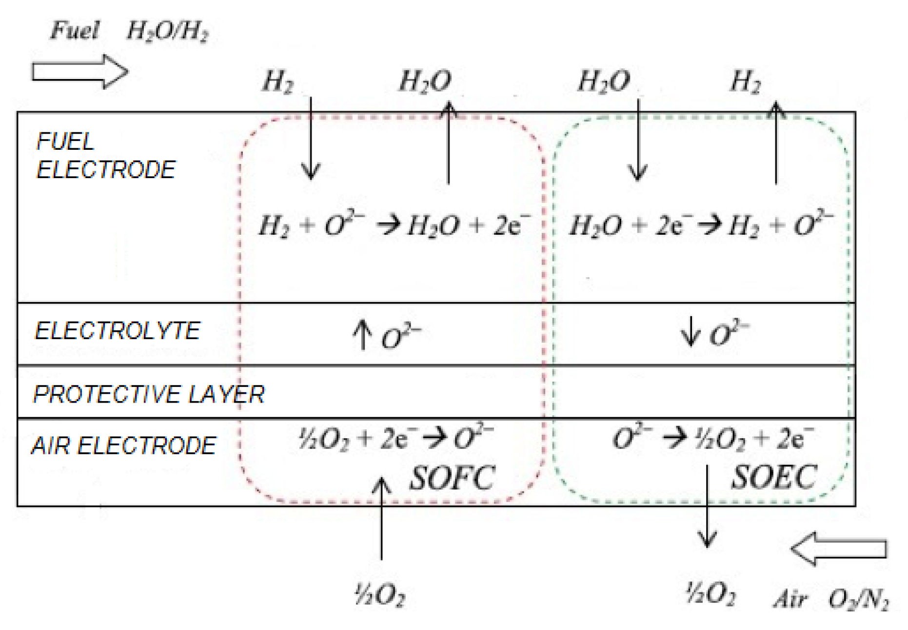
One of the most promising fuel cell technologies is the reversible solid oxide cell (ReSOC). State-of-the-art solid oxide cells consist of a positive electrode-electrolyte-negative electrode (PEN) element. The solid electrolyte is generally made of yttrium-stabilized zirconium (YSZ), the anode of a nickel-impregnated yttria-stabilized zirconia cermet, which mechanically supports the cell, while the cathode is made of a lanthanum strontium cobalt ferrite (LSCF) layer. Generally, a protective layer of either Gadolinium-doped ceria (GDC) or Yttrya-doped ceria (YDC) is added to prevent a secondary face-interface formation [6]. The chemical species flow in channels and react inside the porous electrode. ReSOC has to operate at a high temperature (about 800 °C) because the electrolyte (YSZ) ionic conduction is highly influenced by the cell temperature. The benefit of high temperature operation allows for high electrolysis efficiency as shown by Ferrero et al. [7]. A schematic of a ReSOC is shown in Figure 1.
Various experimental studies focused on solid oxide electrolysis. Three different studies, published in 2008, have highlighted the high measured efficiency of high temperature solid oxide water electrolysis [9], some specific issues of materials and shape of electrodes [10], and control strategies and reactions with oxygen on the anode side [11]. Other tests of solid oxide electrolysis were presented in [12,13,14]. Those tests focused on transient operation, which is fundamental for reversible operation of solid oxide cells [12], on the effect of temperature and steam inlet concentration [13] and on degradation in electrolysis mode [14]. Jung et al. [15] recently presented a complete assessment of the performance of two materials when operated in solid oxide fuel cell (SOFC) and solid oxide electrolysis cell (SOEC) modes, also determining the effect of the reversible operation on materials.
A complete theoretical study dealing with thermodynamics, overpotential and performance of steam electrolysis in pressurized solid oxide cells was presented in [16]. Peters et al. [17] studied the influence of operating parameters on solid oxide electrolysis performance and identified four different efficiency definitions with different amounts and types of heat supply.
Another possible utilization of solid oxide electrolyzer cells is in the so called co-electrolysis of CO and water, which produces a syngas from where either Fischer–Tropsch liquid fuels or CO and H rich gases can be produced for different applications. Jensen et al. proposed to use SOEC to produce Fischer–Tropsch fuels either using atmospheric or pressurized cells [18,19]. Similar results were published by Becker et al. [20], and by Kazempoor and Braun [21], whereas Cinti et al. [22] applied co-electrolysis to investigate the eventual convenience of distributed CO and hydrogen production and centralized F–T fuel synthesis. Co-electrolysis has also been studied for the production of chemicals by producing optimal syngas mixtures with the correct CO/H ratio. To this aim, several studies were published about the performance, the durability and the optimal operation of the SOEC [23,24,25,26].
In all of the previously cited studies, the electrolysis mode is considered the normal mode of operation of the solid oxide cell. Even in the reversible cell tests, the two modes of operation are not considered integrated with hydrogen and steam storage as it could happen in an energy storage system. The term ReSOC or rSOC is used to describe a solid oxide cell that can be operated either to produce power in SOFC mode or to electrolyze steam in SOEC mode. Most of the modeling studies about the performance of ReSOCs have been written by the research group of Braun [27,28,29,30,31,32]. Starting with the first concept presented by Kazempoor and Braun [27] in 2015, where ReSOC are proposed for storing intermittent renewable energy, the subject was studied from different points of view and different levels of detail in [28,29,30,31,32]. Klotz et al. [33] developed a simplified model, which accurately represents the behavior of SOC in both operational modes, while Ferrero et al. [8] presented a model, validated and calibrated it with experimental test. SOEC and ReSOC have also been studied experimentally in order to validate concepts and simulations and to understand aging and deterioration of materials. Among the most complete experimental studies, two deserve to be mentioned:
From the state-of-the-art of the research, it is clear that the ReSOC might be an electric storage technology with a high roundtrip efficiency (>70%) and higher energy density than batteries [28,36]. Wendel proposed in his Ph.D. thesis [28] to store and provide the thermal energy produced and required by the cell (Figure 2) using the C-H-O equilibrium catalyzed by the nickel of the fuel anode. In fact, the use of methane as primary fuel produces an endothermic reaction in power generation mode, while hydrogen and carbon monoxide are produced during electrolysis, and methanation (exothermic reaction) is expected. The problem with this solution is that at the working temperatures and pressures of the state-of-the-art ReSOC (1000 K and atmospheric pressure), methanation reaction practically does not occur. Thus, Wendel proposed to use a lanthanum strontium magnesium gallate (LSGM) electrolyte ReSOC, which is theoretically able to achieve 80% percent cell roundtrip efficiency at 650 °C, which is a much more favorable temperature for methanation reaction, and to increase cell pressure.
This paper describes ReSOC systems, and most of the challenges that have to faced in order to build and operate such a system in both SOEC and SOFC modes with a suitable hydrogen and steam storage system. This could be also considered as a way to store hydrogen and use it efficiently on the same site where it is produced. In fact, the interest for this technology relies on the fact that the user (a SOFC) has a very high efficiency and is located in the same place where the hydrogen is produced, whereas any other solution where hydrogen is produced far from the user requires transport and delivery costs and additional energy.
The ReSOC is a very interesting technology for EES applications because of the high theoretical roundtrip efficiency, which can be enhanced with an appropriate thermal management strategy: in fact, because of the high operating temperature, the stack needs thermal power when performing electrolysis that can be stored when the cell produces electric power increasing the roundtrip efficiency.
One of the most challenging problems is the stack durability: in fact, the different thermal behavior during SOFC and SOEC operation induces thermal stress that can damage the cells. Another important challenge to face is the cell performance degradation. In fact, the cell has to work in both oxidizing and reducing environments, and it is important to develop electrode materials, which are stable in both those operating conditions [37,38,39].
A stand-alone energy storage system can be built by operating the system in both fuel cell and electrolysis modes and storing the gas as “fuel” and “exhaust” species. In addition, a new management strategy for thermal energy and a power plant configuration for ReSOC based EES are presented. Thermal energy is stored directly inside the stack using a sensible heat storage for a small size EES plant or a phase change material (PCM) thermal storage for a large size one.
In all of the plant configurations presented in this paper, the ReSOC stack is based on the Julich F-design anode supported cells (ASC) with YSZ electrolytes, Ni/YSZ hydrogen electrodes and perovskite oxygen electrodes with LSCF. Those cells were chosen since their reliability has been proven in long-term tests in both SOFC and SOEC modes as mentioned above [34].
2. Theoretical Background
2.1. Reversible Solid Oxide Cell Stack
The theoretical work that can be obtained by oxidizing a mole of fuel can be expressed as:
where is the enthalpy variation between reactants and products, the Gibb’s energy change and the entropy difference. The term is the heat produced during this reversible process. The energy required to perform the inverse process can be calculated as:
In this case, ΔG is the share of the total energy that has to be provided as work while is the thermal energy.
At higher temperatures, the thermal energy theoretically required to perform electrolysis and produced in SOFC mode increases, while the ΔH slightly increases [13]. At the typical ReSOC working temperatures, the thermal energy required to perform electrolysis is approximately 30% of the total. The relationship between current and voltage in a ReSOC is a fundamental characteristic of the cell efficiency and is generally calculated from the open circuit voltage. The open circuit voltage () is estimated by the Nernst potential, calculated as:
where n is the number of electrons involved in the reaction, ΔG is the Gibbs free energy variation and F is the Faraday constant. Expanding the Gibbs free energy term follows:
where is Gibbs free energy variation in standard conditions, y, y and y are the molar fractions of hydrogen, oxygen and steam, respectively, p is the reactant pressure and is the reference pressure.
The voltage difference from the Open Circuit Voltage (OCV) in each operational mode, due to a current dependent overpotential caused by the internal losses due to irreversible processes, determines the cell voltage. The overpotential is typically divided into activation, concentration and ohmic [8].
Activation loss derives from the chemical disequilibrium, and they are modeled with the Butler–Volmer equation. The activation overpotential in solid oxide cells, working in electrolysis mode, is smaller than in low temperature electrochemical cells. Activation overpotential slightly increases with current density at normal operation temperatures.
Concentration losses are mainly due to the transport phenomena inside the porous anode because it is over ten times thicker than the cathode. In fact, most of the electrochemical reactions occur at the interface between electrolyte and electrodes, and the reactant concentrations in that layer are different from the bulk ones.
The ohmic overpotential derives from the electric and ionic resistance of electrodes and electrolyte, respectively; in particular, the ionic conductivity is highly influenced by the temperature. All of the overpotential components described grow with the current density.
Cell potential can be expressed as [30]:
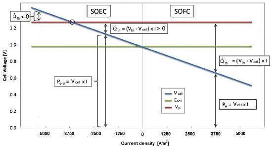
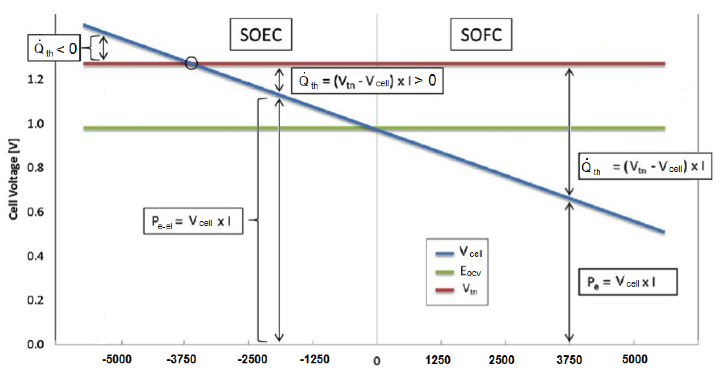
where is –1 in SOFC mode and +1 in SOEC mode. The thermoneutral potential is the potential at which the heat generated by the Joule effect into the cell, due to the current flow, is equal to the heat demand of the electrolysis reaction, and it is defined as:
where ΔH is calculated at the working temperature.
The electric power produced or needed by the cell can be calculated as:
where S is the active surface of the cell and J the current density (positive for SOFC mode and negative for SOEC mode). The thermal power produced or required is:
During electrolysis, the cell needs thermal energy until the cell potential reaches the thermoneutral voltage. At higher voltage, the cell also produces thermal power in SOEC mode. The most important evaluation parameter for an EES system is the roundtrip efficiency, which is defined as the ratio of the net energy generated in SOFC mode to the total energy supplied in SOEC mode:
where and are the total electric energy produced and consumed by the stack in SOFC and SOEC mode, respectively, while and represent the energy consumed by the auxiliary systems. When considering only the ReSOC stack, the roundtrip efficiency is defined as:
where and are the average cell potential during SOFC and SOEC mode. It is important to underline that this definition of the roundtrip efficiency does not take into account the internal energy variation of the system during the working cycle. In this study, the charge and discharge times have been assumed the same since the main focus was on the possibility to operate a solid oxide cell in reverse mode with a high temperature (hot) storage. However, in general applications, charge and discharge times may be different. This can be achieved by sizing the storage systems appropriately. The stack power control is performed by keeping the utilization factor constant. This parameter is defined as the ratio between the consumed and inlet reagents, which is defined during SOFC mode operation as:
During SOEC mode operation, the utilization factor is calculated as follows:
A representative voltage-current plot for a ReSOC is shown in Figure 2.
The cell chosen for this study is a state-of-the-art cell with Ni:YSZ fuel electrodes, YSZ electrolytes and LSCF air electrodes, with a protective layer made of YDC. A schematic of the cell can be found in Figure 1. The electrochemical and thermal models of the cell have been developed by Ferrero et al. [8]. They allow for calculating cell overpotential, and consequently the polarization curve, when cell temperature and inlet gas compositions are known. The electrochemical reactions are considered faster than the thermal dynamics of the cell, so the electrochemical model is stationary, while the thermal model is time dependent, to take into account cell temperature variation. The reactant concentrations needed to calculate the polarization curve are the average between inlet and outlet because the current density is supposed uniform inside the cell.
Some more assumptions have been made in order to have a simple and analytic cell mode:
- stationary plug flow with negligible gas conduction in both anode and cathode channel;
- uniform temperature inside cells;
- isopotential electrodes;
- reactant concentrations and molar fractions used to calculate cell potential are the mean ones between inlet and outlet.
2.2. Heat Exchangers
The heat exchangers in the proposed plants preheat reactants and cool down products, and they are necessary in both the configurations. In the proposed plants, heat exchangers’ dynamic behavior was neglected because their transients are faster than those of the stacks, which have a higher inertia. The efficiency method, which is often used to size heat exchangers, can model them in a simple and coherent way. A value of the heat exchanger efficiency has been assumed as constant in all operating conditions.
2.3. Compressors and Expanders
Both compression and expansion devices have been modeled assuming an isentropic efficiency. Thermodynamic properties of chemical species have been calculated using the REFPROP software [40], while thermodynamic properties of mixtures are calculated with the assumption of ideal mixtures.
3. Thermal Management Strategies
The SOEC mode operation, as shown in Figure 1, can be either exothermic or endothermic, depending on the current density. To achieve steady state operation, the stack has to work in a slightly exothermic regime, which implies a high current density, irreversible processes, and consequently, low system efficiency. For this reason, in order to increase the EES performance, the stored thermal energy during the SOFC mode has to be recovered during SOEC mode.
In the literature, McElroy proposed to store thermal energy by using lithium fluoride (LiF), whose fusion temperature is 848 °C, as a PCM in direct contact with the cell stack [41]. This solution presented several problems due to the low thermal conductivity, which produces a significant temperature difference between cell and PCM.
Another problem is that lithium fluoride, while changing phase from solid to liquid, increases its volume by 30% [42]. Moreover, McElroy experiments were carried out using an electrode supported cell stack, which has a working temperature about 100 °C higher than state-of-the-art ASC, for the PCM to operate at lower temperatures.
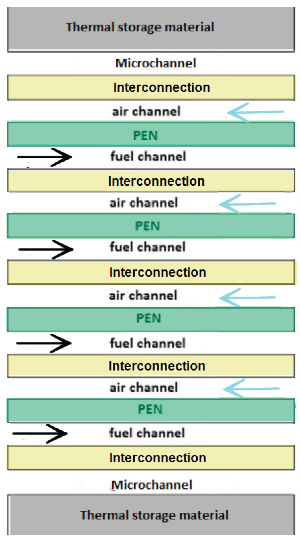
In this work, two different thermal storage strategies are proposed: sensible heat storage using a ceramic material, such as aluminum oxide, or latent heat storage using a PCM, preferably an eutectic metal alloy, with a high thermal conductivity and low volume change. The thermal storage material is in close contact with the stack, and to decrease the contact thermal resistance, micro-channels are used, allowing a higher heat transfer coefficient and lower thermal gradients. A schematic representation of the stack configuration can be found in Figure 3.
The EES can be theoretically operated in SOEC mode for a very long time with no external heat source, working slightly above the thermoneutral potential to keep the stack temperature constant. This would, however, decrease the system roundtrip efficiency.
4. Modeling Approach
System modeling approach is used to determine suitable system configurations and operating conditions that allow a high roundtrip efficiency. Two plant configurations have been proposed and modeled with differences in thermal and water management. The models were built using the Matlab/Simulink software (Mathworks, Natick, MA, USA).
4.1. Condensed Vapor Configuration
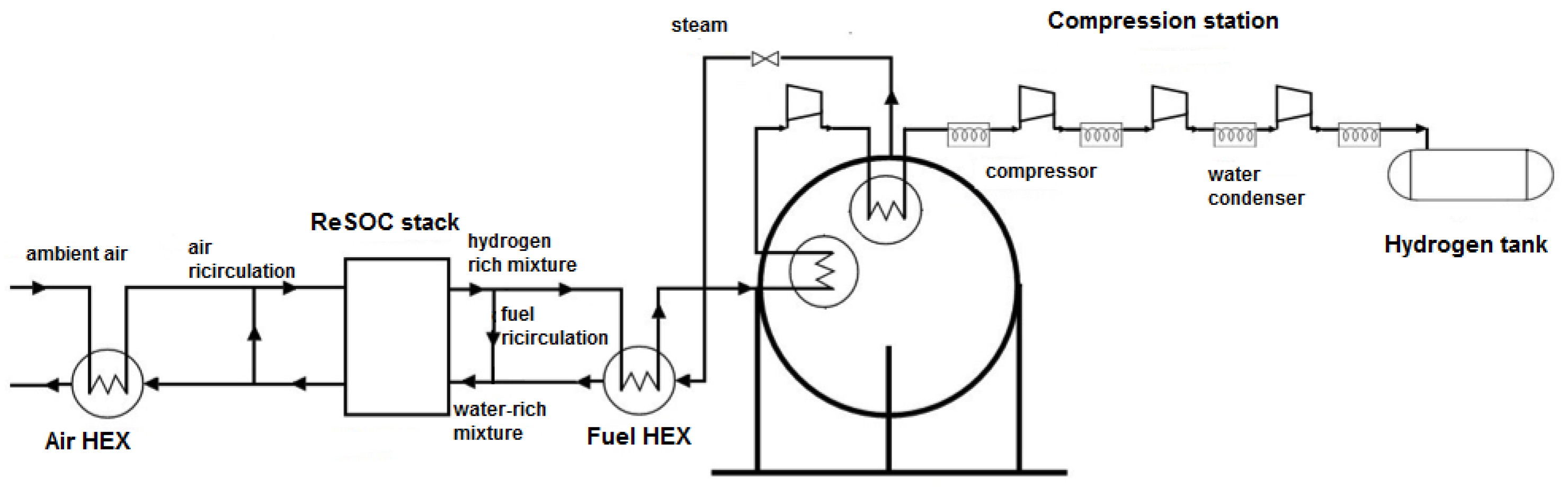
The condensed vapor configuration is shown in Figure 4 when the system is operated in SOFC mode and in Figure 5 when the system is operated in SOEC mode. In both SOFC and SOEC modes, the steam that comes from the ReSOC stack is condensed after every compression stage, so that almost pure hydrogen is stored in the tank. In the condensed vapor configuration, shown in Figure 4, when the ReSOC stack operates in SOFC mode, the excess thermal energy is stored in a steam generator tank and the steam contained at the outlet of the stack is condensed after every compression, so that the hydrogen contained in the pressurized tank is almost pure, with a higher energy density. Both hydrogen and ambient air are preheated in, respectively, the air heat exchanger (HEX) and the fuel HEX before entering the ReSOC stack. The ambient air molar flow is higher during SOFC operation in order to have a high oxygen molar fraction in the cell, while during SOEC operation, air has to only blow away the oxygen formed in the electrode; furthermore, since the heat exchanger efficiency is not one, a larger air flow rate implies higher stack thermal loss. In order to control the water molar fraction entering the cell and to further increase the temperature of the gas, fuel is recirculated in both SOFC and SOEC operation.
In SOEC mode, steam is extracted from the steam generator tank, expanded to the stack pressure and preheated in the fuel HEX.
This configuration allows a high stack roundtrip efficiency because it is possible to operate in both SOFC and SOEC modes with high reactant molar fractions. The water steam necessary during SOEC mode is generated in the storage steam generator tank: the gas exiting the fuel HEX and the first compression stage flows through heat exchangers heating the tank. In fact, at nominal conditions ( = 1000 K, p = 1 atm, = 5000 A/m), the thermal power produced in SOFC mode is approximately 20 W, while the heat needed in the SOEC is about four times smaller (5–8 W). The surplus heat is used to generate the steam for the electrolysis: during SOFC operation, part of the thermal energy goes to the thermal storage material inside the stack itself, and part is transferred by the gas flows processed by the stack and by a cooling fluid to the steam generator, which actually works as a boiler drum. During SOFC operation mode, its temperature and pressure increase, while during SOEC mode, when steam is required, the tank pressure decreases promoting water evaporation. The pressure inside the steam generator can be controlled expanding part of the fluid in a steam turbine. This configuration is applicable only for low capacity EES or for thermally integrated plants because of the thermal energy needed to generate steam during electrolysis. The thermal energy required is at low temperature and can be provided by solar collectors.
In Table 1, the coefficients used for the simulation are reported.
A parametric analysis has been carried out to find the combination of reactant utilization factors and reactant inlet molar fractions that provide the highest roundtrip efficiency. Since the system does not operate under stationary conditions and the heat needed for electrolysis is stored as sensible heat, an evaluation cycle has been defined. This cycle consists of two hours of nominal power SOFC mode followed by electrolysis that ends when the hydrogen initial reservoir is full again. The parametric analysis shows how the roundtrip efficiency is almost constant. This was predictable, since a higher utilization factor means lower molar flow rates to compress and lower compression work, but it also means lower stack roundtrip efficiency. The same is true for the inlet reactant concentration: a higher reactant molar fraction produces higher stack efficiency, with lower fuel recirculation and higher compression work.
The best roundtrip efficiency achieved in these conditions is around 72% for both the sensible and the PCM heat storage, with 0.6 utilization factor and 0.8 inlet reactant molar fraction for both SOFC and SOEC operation.
This configuration presents some critical issues: first of all, even when PCM is used for thermal storage, it is not possible to perform electrolysis for a long time because of the limited steam availability. In fact, if no additional thermal source heats the steam tank, its pressure drops below the atmospheric one. Another critical aspect, due to the fast temperature change, appears when switching operation modes: if the stack operates in SOFC mode, the cell temperature is higher than the thermal storage material temperature (either ceramic material or PCM), because heat is transferred from the stack to the heat storage. If a step change of operation mode occurs and the electrolysis begins, the stack needs thermal energy that cannot be provided by the thermal storage material, because its temperature is lower. Therefore, the stack temperature drops quickly until it reaches the material’s temperature, because of its low thermal inertia.
The roundtrip efficiency for this concept can be theoretically improved with pressurized stack operation. In fact, a lower compression energy would be required, thus increasing roundtrip efficiency because of the higher reactant concentration. Pressurized SOFC and SOEC operation has also been studied at Idaho National Laboratory [43]. In order to keep pressure equilibrium inside and outside cell sealing, the stack was inserted into a pressurized nuclear vessel. However, stack reliability was compromised and no experimental stack survived longer than 900 h because pressure equilibrium could not be perfectly guaranteed. Moreover, the ReSOC electrochemical mode was validated only with ambient pressure operation.
Pressurized stack operation, for this configuration, would cause further limitations: the steam tank minimum pressure should be the stack pressure, and the minimum temperature should increase, decreasing the thermal energy recovered. For this reason, pressurized stacks would not significantly increase the roundtrip efficiency.
4.2. Stored Vapor Configuration
To enhance the EES system flexibility operation, another configuration is proposed. This new configuration does not need a steam generator because the water rich mixture needed for electrolysis is stored in the exhaust tank, so the only limitation to the electrolysis operation time comes from the thermal storage capacity.
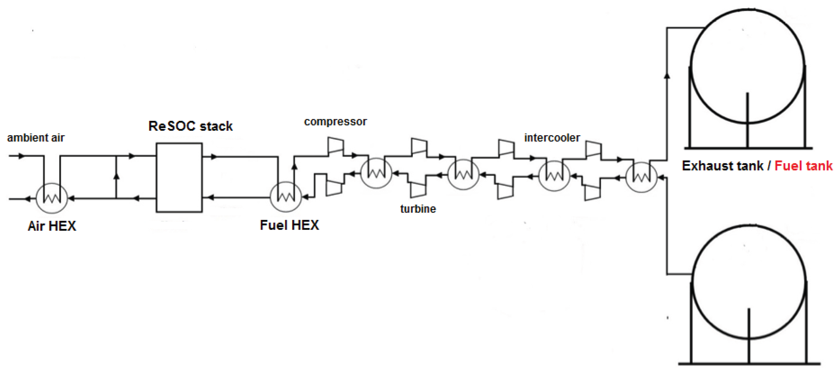
In the stored vapor configuration, there are two pressurized tanks, one for the fuel rich and one for the water rich gas mixture. When producing electrical power, the fuel rich mixture is expanded and enters the ReSOC stack, while the exiting water rich mixture is compressed and finally enters the steam rich tank. When performing electrolysis, the water rich mixture enters the ReSOC stack and the hydrogen rich mixture is compressed and stored in the fuel tank (Figure 6). To keep water in vapor form, tank temperature must be higher than the saturation temperature at the storage pressure.
In order to decrease the energy needed to compress the high temperature mixture, the expansion energy is recovered as shown in Figure 6. The compression is divided into four intercooled stages: after every compression, the hot gas is cooled inside the heat exchanger, heating the expanding gas before it enters the turbine for the decompression.
This configuration presents a higher flexibility than the previous one because steam is stored and the steam generator, which was the most limiting element of the previous system, is no longer necessary. The main problem with this configuration is that achieving high roundtrip efficiency requires high reactant utilization factors to reduce the compressed molar flow, i.e., the compression energy. With high utilization factors, some of the assumptions made in the stack model cannot be accepted anymore: current cannot be considered uniform inside the cells and the cell voltage calculated by the model is not correct.
Moreover, thermal gradients dangerous for the stack could arise because of the non-uniform current distribution. Therefore, the results shown in these conditions can be seen as a simple estimation of the system performance. A parametric analysis has also been performed for the stored vapor configuration, and the highest calculated roundtrip efficiency was 64%, obtained for a 0.9 utilization factor for both hydrogen and water in SOFC and SOEC operation mode (Table 2). Pressurized stack operation could be an interesting way to decrease compression energy and increase roundtrip efficiency. A plant simulation has been performed for this condition, and the highest roundtrip efficiency achieved was 74%, always with 0.9 reactant utilization factor for both SOFC and SOEC operation.
5. Conclusions
The thermodynamics of a ReSOC system have been thoroughly analyzed and a methodology developed to predict theoretical roundtrip performance in a duty cycle in order to understand the potential applications of this new technology as an electric energy storage system.
A state-of-the-art solid oxide cell (LSCF air electrode, YSZ electrolyte, and YSZ-Ni fuel electrode) model was used to characterize the impact of a variety of cell operating parameters on the stack efficiency. With the aim of internally recovering part of the thermal energy produced in SOFC mode, and using it in SOEC mode, a sensible heat storage system was studied, and all the PCM critical aspects discussed. The increased thermal inertia is useful to stabilize stack operation during transients but can cause some issues during operation inversion (i.e., from SOFC to SOEC or from SOEC to SOFC).
The calibrated ReSOC model was also coupled with the thermodynamic balance of plant model to simulate dynamic roundtrip operation of ReSOC energy storage systems in an estimated duty cycle. The system modeling capabilities were applied to two different plant configurations: a stored vapor and a condensed vapor configuration.
Both of those conceptual plants have been tested and possible performance improvements have been evaluated. The concepts of the stored vapor and condensed vapor configurations were optimized, finding the working parameters which maximized roundtrip efficiency. The vapor condensed plant showed an almost constant efficiency over a wide range of operating conditions. The optimized stored vapor plant has almost the same performance of the condensed vapor plant, but it needs higher reactant utilization factors. This could cause problems in cell operation such as temperature stress or loss of performance that cannot be analyzed because of the assumptions used in the stack model.
The optimized stored vapor model was also tested in pressurized stack conditions to evaluate improvements of the system performance due to the lower required compression power. The stored vapor plant roundtrip efficiency increased from 64% to 74%, while the condensed vapor plant showed problems due to the lower thermal power available for water evaporation with pressurized stack operation.
Acknowledgments
Financial contribution of PRA2016 is gratefully acknowledged.
Author Contributions
This paper presents the main results of the Master’s Thesis of Paolo di Giorgio under the supervision of Umberto Desideri. Umberto Desideri conceived the idea of the study and Paolo di Giorgio developed the models and calculated the results. Both authors discussed the methodology, decided the simulations to be performed, analyzed the data and wrote the paper.
Conflicts of Interest
Paolo di Giorgio and Umberto Desideri declare no conflict of interest.
References
- Dunn, B.; Kamath, H.; Tarascon, J.M. Electrical energy storage for the grid: A battery of choices. Science 2011, 334, 928–935. [Google Scholar] [CrossRef] [PubMed]
- Evans, A.; Strezov, V.; Evans, T.J. Assessment of utility energy storage options for increased renewable energy penetration. Renew. Sustain. Energy Rev. 2012, 16, 4141–4147. [Google Scholar] [CrossRef]
- Akhil, A.A.; Huff, G.; Currier, A.B.; Kaun, B.C.; Rastler, D.M.; Chen, S.B.; Cotter, A.L.; Bradshaw, D.T.; Gauntlett, W.D. Doe/epri 2013 Electricity Storage Handbook in Collaboration with NRECA; Sandia National Laboratories: Albuquerque, NM, USA, 2013. [Google Scholar]
- Kasai, S. Hydrogen electrical energy storage by high temperature steam electrolysis for next millennium energy security. Int. J. Hydrog. Energy 2014, 39, 21358–21370. [Google Scholar] [CrossRef]
- Gahleitner, G. Hydrogen from renewable electricity: An international review of power-to-gas pilot plants for stationary applications. Int. J. Hydrog. Energy 2013, 38, 2039–2061. [Google Scholar] [CrossRef]
- Bertei, A. Mathematical Modeling of Solid Oxide Fuel Cells. Ph.D. Thesis, University of Pisa, Pisa, Itatly, 10 February 2014. [Google Scholar]
- Ferrero, D.; Lanzini, A.; Santarelli, M.; Leone, P. A comparative assessment on hydrogen production from low- and high-temperature electrolysis. Int. J. Hydrog. Energy 2013, 38, 3523–3536. [Google Scholar] [CrossRef]
- Ferrero, D.; Lanzini, A.; Leone, P.; Santarelli, M. Reversible operation of solid oxide cells under electrolysis and fuel cell modes: Experimental study and model validation. Chem. Eng. J. 2015, 274, 143–155. [Google Scholar] [CrossRef]
- Brisse, A.; Schefold, J.; Zahid, M. High temperature water electrolysis in solid oxide cells. Int. J. Hydrog. Energy 2008, 33, 5375–5382. [Google Scholar] [CrossRef]
- Ni, M.; Leung, M.K.H.; Leung, D.Y.C. Technological development of hydrogen production by solid oxide electrolyzer cell (SOEC). Int. J. Hydrog. Energy 2008, 33, 2337–2354. [Google Scholar] [CrossRef]
- Udagawa, J.; Aguiar, P.; Brandon, N.P. Hydrogen production through steam electrolysis: Control strategies for a cathode-supported intermediate temperature solid oxide electrolysis cell. J. Power Sources 2008, 180, 354–364. [Google Scholar] [CrossRef]
- Petipas, F.; Fu, Q.; Brisse, A.; Bouallou, C. Transient operation of a solid oxide electrolysis cell. Int. J. Hydrog. Energy 2013, 38, 2957–2964. [Google Scholar] [CrossRef]
- Penchini, D.; Cinti, G.; Discepoli, G.; Desideri, U. Theoretical study and performance evaluation of hydrogen production by 200 W solid oxide electrolyzer stack. Int. J. Hydrog. Energy 2014, 39, 9457–9466. [Google Scholar] [CrossRef]
- Li, Q.; Zheng, Y.; Guan, W.; Jin, L.; Xu, C.; Wang, W.G. Achieving high-efficiency hydrogen production using planar solid-oxide electrolysis stacks. Int. J. Hydrog. Energy 2014, 39, 10833–10842. [Google Scholar] [CrossRef]
- Jung, G.B.; Fang, L.H.; Lin, C.Y.; Nguyen, X.V.; Yeh, C.C.; Lee, C.Y.; Yu, J.W.; Chan, S.H.; Lee, W.T.; Chang, S.W.; et al. Electrochemical performance and long-term durability of a reversible solid oxide fuel cell. Int. J. Electrochem. Sci. 2015, 10, 9089–9104. [Google Scholar]
- Henke, M.; Willich, C.; Kallo, J.; Friedrich, K.A. Theoretical study on pressurized operation of solid oxide electrolysis cells. Int. J. Hydrog. Energy 2014, 39, 12434–12439. [Google Scholar] [CrossRef]
- Peters, R.; Deja, R.; Blum, L.; Nguyen, V.N.; Fang, Q.; Stolten, D. Influence of operating parameters on overall system efficiencies using solid oxide electrolysis technology. Int. J. Hydrog. Energy 2015, 40, 7103–7113. [Google Scholar] [CrossRef]
- Jensen, S.H.; Larsen, P.H.; Mogensen, M. Hydrogen and synthetic fuel production from renewable energy sources. Int. J. Hydrog. Energy 2007, 32, 3253–3257. [Google Scholar] [CrossRef]
- Jensen, S.H.; Sun, X.; Ebbesen, S.D.; Knibbe, R.; Mogensen, M. Hydrogen and synthetic fuel production using pressurized solid oxide electrolysis cells. Int. J. Hydrog. Energy 2010, 35, 9544–9549. [Google Scholar] [CrossRef]
- Becker, W.L.; Braun, R.J.; Penev, M.; Melaina, M. Production of Fischer–Tropsch liquid fuels from high temperature solid oxide co-electrolysis units. Energy 2012, 47, 99–115. [Google Scholar] [CrossRef]
- Kazempoor, P.; Braun, R.J. Hydrogen and synthetic fuel production using high temperature solid oxide electrolysis cells (SOECs). Int. J. Hydrog. Energy 2015, 40, 3599–3612. [Google Scholar] [CrossRef]
- Cinti, G.; Baldinelli, A.; Di Michele, A.; Desideri, U. Integration of solid oxide electrolyzer and Fischer–Tropsch: A sustainable pathway for synthetic fuel. Appl. Energy 2016, 162, 308–320. [Google Scholar] [CrossRef]
- Graves, C.; Ebbesen, S.D.; Mogensen, M. Co-electrolysis of CO2 and H2O in solid oxide cells: Performance and durability. Solid State Ion. 2011, 192, 398–403. [Google Scholar] [CrossRef]
- Ni, M. 2D thermal modeling of a solid oxide electrolyzer cell (SOEC) for syngas production by H2O/CO2 co-electrolysis. Int. J. Hydrog. Energy 2012, 37, 6389–6399. [Google Scholar] [CrossRef]
- Ni, M. An electrochemical model for syngas production by co-electrolysis of H2O and CO2. J. Power Sources 2012, 202, 209–216. [Google Scholar] [CrossRef]
- Alenazey, F.; Alyousef, Y.; Almisned, O.; Almutairi, G.; Ghouse, M.; Montinaro, D.; Ghigliazza, F. Production of synthesis gas (H2 and CO) by high-temperature Co-electrolysis of H2O and CO2. Int. J. Hydrog. Energy 2015, 40, 10274–10280. [Google Scholar] [CrossRef]
- Kazempoor, P.; Braun, R.J. Model validation and performance analysis of regenerative solid oxide cells for energy storage applications: Reversible operation. Int. J. Hydrog. Energy 2015, 40, 5955–5971. [Google Scholar] [CrossRef]
- Wendel, C.H. Design and analysis of reversible solid oxide cell systems for electrical energy storage. Ph.D. Thesis, Colorado School of Mines, Arthur Lakes Library, Golden, CO, USA, 2015. [Google Scholar]
- Wendel, C.H.; Kazempoor, P.; Braun, R.J. Novel electrical energy storage system based on reversible solid oxide cells: System design and operating conditions. J. Power Sources 2015, 276, 133–144. [Google Scholar] [CrossRef]
- Wendel, C.H.; Gao, Z.; Barnett, S.A.; Braun, R.J. Modeling and experimental performance of an intermediate temperature reversible solid oxide cell for high-efficiency, distributed-scale electrical energy storage. J. Power Sources 2015, 283, 329–342. [Google Scholar] [CrossRef]
- Wendel, C.H.; Braun, R.J. Design and techno-economic analysis of high efficiency reversible solid oxide cell systems for distributed energy storage. Appl. Energy 2016, 172, 118–131. [Google Scholar] [CrossRef]
- Wendel, C.H.; Kazempoor, P.; Braun, R.J. A thermodynamic approach for selecting operating conditions in the design of reversible solid oxide cell energy systems. J. Power Sources 2016, 301, 93–104. [Google Scholar] [CrossRef]
- Klotz, D.; Leonide, A.; Weber, A.; Ivers-Tiffée, E. Electrochemical model for SOFC and SOEC mode predicting performance and efficiency. Int. J. Hydrog. Energy 2014, 39, 20844–20849. [Google Scholar] [CrossRef]
- Nguyen, V.N.; Fang, Q.; Packbier, U.; Blum, L. Long-term tests of a Jülich planar short stack with reversible solid oxide cells in both fuel cell and electrolysis modes. Int. J. Hydrog. Energy 2013, 38, 4281–4290. [Google Scholar] [CrossRef]
- Sar, J.; Schefold, J.; Brisse, A.; Djurado, E. Durability test on coral Ce0.9Gd0.1O2−δ-La0.6Sr0.4Co0.2Fe0.8O3−δ with La0.6Sr0.4Co0.2Fe0.8O3−δ current collector working in SOFC and SOEC modes. Electrochim. Acta 2016, 201, 57–69. [Google Scholar] [CrossRef]
- Zhang, X.; Chan, S.H.; Ho, H.K.; Tan, S.C.; Li, M.; Li, G.; Li, J.; Feng, Z. Towards a smart energy network: The roles of fuel/electrolysis cells and technological perspectives. Int. J. Hydrog. Energy 2015, 40, 6866–6919. [Google Scholar] [CrossRef]
- Xu, N.; Li, X.; Zhao, X.; Goodenough, J.B.; Huang, K. A novel solid oxide redox ow battery for grid energy storage. Energy Environ. Sci. 2011, 4, 4942–4946. [Google Scholar] [CrossRef]
- Hughes, G.A.; Yakal-Kremski, K.; Barnett, S.A. Life testing of LSM-YSZ composite electrodes under reversing-current operation. Phys. Chem. Chem. Phys. 2013, 15, 17257–17262. [Google Scholar] [CrossRef] [PubMed]
- Hughes, G.A.; Yakal-Kremski, K.; Call, A.V.; Barnett, S.A. Durability testing of solid oxide cell electrodes with current switching. J. Electrochem. Soc. 2012, 159, F858–F863. [Google Scholar] [CrossRef]
- Lemmon, E.W.; Huber, M.L.; McLinden, M.O. NIST Standard Reference Database 23: Reference Fluid Thermodynamic and Transport Properties-REFPROP; Version 9.1. User’s Guide; National Institute of Standards and Technology, Standard Reference Data Program: Gaithersburg, MD, USA, 2013.
- McElroy, J.F.; Hickey, D.B.; Mitlitsky, F. Optimization and Demonstration of a Solid Oxide Regenerative Fuel Cell System; Ion America Corporation: Moffett Field, CA, USA, 2006. [Google Scholar]
- Kenisarin, M.K. High-temperature phase change materials for thermal energy storage. Renew. Sustain. Energy Rev. 2008, 14, 955–970. [Google Scholar] [CrossRef]
- O’Brien, J.E.; Zhang, X.; Housley, G.K.; DeWall, K.; Moore-McAteer, L.; Tao, G. High Temperature Electrolysis Pressurized Experiment Design, Operation; Report INL/EXT-12-26891; Idaho National Laboratory: Idaho Falls, ID, USA, 2012. [Google Scholar]
Figure 1.
Schematic of a reversible solid oxide cell (ReSOC) operational modes. Adapted from [8]. SOFC: solid oxide fuel cell; SOEC: solid oxide electrolysis cell.
Figure 1.
Schematic of a reversible solid oxide cell (ReSOC) operational modes. Adapted from [8]. SOFC: solid oxide fuel cell; SOEC: solid oxide electrolysis cell.

Figure 2.
Typical SOFC–SOEC polarization curve. In this picture, the electrical and thermal power in fuel cell and electrolysis mode are shown. Adapted from [13].
Figure 2.
Typical SOFC–SOEC polarization curve. In this picture, the electrical and thermal power in fuel cell and electrolysis mode are shown. Adapted from [13].

Figure 3.
Stack configuration.

Figure 4.
Condensed vapor plant configuration in SOFC mode.

Figure 5.
Condensed vapor plant configuration in SOEC mode.

Figure 6.
Vapor stored plant configuration. During SOFC mode (in black), the hydrogen rich gas comes out of the Fuel tank and is expanded in the ReSOC stack while steam rich gas is compressed in the Exhaust tank. During SOEC operation (in red) steam rich gas is expanded from the Fuel tank to the ReSOC stack and hydrogen rich gas is compressed and stored in the Exhaust tank.


| Parameter | Value |
|---|---|
| Compression isoentropic efficiency | 0.8 |
| Pressure ratio (1st stage) | 4 |
| Pressure ratio (other stages) | 3 |
| Heat exchanger efficiency | 0.8 |
| Hydrogen tank pressure | 108 bar |
| PCM melting temperature | 1050 K |
| Optimal Working Parameters | |
| Inlet molar fraction (SOFC) | 0.8 |
| Inlet molar fraction (SOEC) | 0.8 |
| utilization factor | 0.6 |
| utilization factor | 0.6 |
| Parameter | Value |
|---|---|
| Compression isentropic efficiency | 0.8 |
| Expansion isentropic efficiency | 0.85 |
| Pressure ratio (1st stage) | 4 |
| Pressure ratio (other stages) | 3 |
| Heat exchanger efficiency | 0.8 |
| Tank pressure | 108 bar |
| PCM melting temperature | 1050 K |
| Optimal working parameters | |
| utilization factor | 0.9 |
| utilization factor | 0.9 |
© 2016 by the authors; licensee MDPI, Basel, Switzerland. This article is an open access article distributed under the terms and conditions of the Creative Commons Attribution (CC-BY) license (http://creativecommons.org/licenses/by/4.0/).
Share and Cite
MDPI and ACS Style
Di Giorgio, P.; Desideri, U. Potential of Reversible Solid Oxide Cells as Electricity Storage System. Energies 2016, 9, 662. https://doi.org/10.3390/en9080662
AMA Style
Di Giorgio P, Desideri U. Potential of Reversible Solid Oxide Cells as Electricity Storage System. Energies. 2016; 9(8):662. https://doi.org/10.3390/en9080662
Chicago/Turabian StyleDi Giorgio, Paolo, and Umberto Desideri. 2016. "Potential of Reversible Solid Oxide Cells as Electricity Storage System" Energies 9, no. 8: 662. https://doi.org/10.3390/en9080662
Note that from the first issue of 2016, this journal uses article numbers instead of page numbers. See further details here.