Article

A Novel Neural Network Vector Control for Single-Phase Grid-Connected Converters with L, LC and LCL Filters

Department of Electrical and Computer Engineering, The University of Alabama, Tuscaloosa, AL 35401, USA
*
Author to whom correspondence should be addressed.
Energies 2016, 9(5), 328; https://doi.org/10.3390/en9050328
Submission received: 23 February 2016 / Revised: 15 April 2016 / Accepted: 20 April 2016 / Published: 29 April 2016

Abstract

:
This paper investigates a novel recurrent neural network (NN)-based vector control approach for single-phase grid-connected converters (GCCs) with L (inductor), LC (inductor-capacitor) and LCL (inductor-capacitor-inductor) filters and provides their comparison study with the conventional standard vector control method. A single neural network controller replaces two current-loop PI controllers, and the NN training approximates the optimal control for the single-phase GCC system. The Levenberg–Marquardt (LM) algorithm was used to train the NN controller based on the complete system equations without any decoupling policies. The proposed NN approach can solve the decoupling problem associated with the conventional vector control methods for L, LC and LCL-filter-based single-phase GCCs. Both simulation study and hardware experiments demonstrate that the neural network vector controller shows much more improved performance than that of conventional vector controllers, including faster response speed and lower overshoot. Especially, NN vector control could achieve very good performance using low switch frequency. More importantly, the neural network vector controller is a damping free controller, which is generally required by a conventional vector controller for an LCL-filter-based single-phase grid-connected converter and, therefore, can overcome the inefficiency problem caused by damping policies.

1. Introduction

In small-scale photovoltaic and residential electric vehicle charging applications, single-phase grid-connected converters (GCCs) are serving as the critical interface between renewable energy sources and the utility grid [1,2,3]. Filters are required to connect a GCC to the grid in order to attenuate the switching harmonics generated by GCCs. Typical filters in GCC applications are L (inductor) and LCL (inductor-capacitor-inductor) filters. The LC ( inductor-capacitor) filter-based GCC is also used, particularly in microgrid applications [4].
In existing technologies, vector control is widely used to control three-phase GCCs [5,6], due to its great advantages. However, to apply vector control to a single-phase GCC, an imaginary circuit needs to be created. To create the imaginary circuit, the simplest way is to delay real circuit variables by a quarter cycle of the fundamental period [7]. Nevertheless, this will result in a delay of the system, thereby deteriorating the system dynamic response. Another simple method is to use differentiation [8] to avoid the delay. However, under distorted grid voltage conditions, the performance of the differentiation approach can be deteriorated significantly. A more complicated fictive axis emulation technique to create the imaginary circuit with a fictive axis running concurrently with the real circuit [9] was proposed to improve the poor dynamics of the conventional approaches.
The basis of vector control for a single-phase GCC is equivalent to that for a three-phase GCC. However, recent studies indicate that the standard vector controllers show limitations [10], in particular decoupling inaccuracy. Even for a grid-connected inverter with a simple L filter, the conventional standard approach still surfers from the decoupling inaccuracy problem. Generally, in the stage of designing and tuning a conventional vector controller, the control policy is to drop the cross-coupling terms (normally called compensation terms), which are then added back to the conventional controller to formulate the final control action in the implementation. This strategy would present a decoupling inaccuracy and deteriorate the performance of a conventional vector controller. Especially when the output filter is an LCL filter, it could cause potential oscillatory and/or unstable dynamic behavior if the LCL filter or the controller is not properly damped [6].
Due to the challenges associated with creating the imaginary circuit for a single-phase GCC,single-phase active power and reactive power (p-q) theory [11,12] has been proposed and used to directly control the instantaneous active and reactive power flow through the inverter to the grid [13,14]. However, some research [15,16] indicated that the p-q theory misinterprets the power properties of electrical systems. It was also pointed out in [17] that a fast current-loop controller is critical to assure the highest power quality in terms of harmonics and unbalance for a GCC. Therefore, developing advanced vector control technology with nested power and current control loops is critical for the control of single-phase GCCs.
Besides the p-q theory, most of the dominate control strategies for a single-phase inverter are proportional resonant (PR) and sliding mode control. The PR control has been studied by many researchers [3,18,19]. The advantage of the PR control is that it does not need to create the imaginary circuit. Even though the PR control does not show steady-state error in grid current, however, this kind of control strategy is sensitive to the frequency variations in the system. Further, it generally needs a high sampling frequency (e.g., 15 kHz) and switching frequency (e.g., 15 kHz) [3], which tend to cause more energy loss. The sliding-mode control [20] of a single-phase grid-connected converter with an LCL filter has been done by many researchers to solve its associated instability issues [21,22], which is a robust controller with a high stability in a wide range of operating conditions; however, the sliding-mode control suffers from the well-known chattering problem.
Recently, significant research has been reported on dynamic programming (DP) [23] for the optimal control of nonlinear systems [24]. Adaptive critic designs (ACD) constitute a class of approximate dynamic programming (ADP) methods, which use incremental optimization techniques combined with parametric structures to approximate the optimal cost and control of a system [25,26]. Heuristic dynamic programming (HDP) and dual heuristic programming (DHP) were proposed and implemented to control a turbogenerator [27]. In [28,29], an ADP-based neural network (NN) controller is trained to control a three-phase L filter-based GCC system. The ADP-based NN control of the three-phase [30] and single-phase [31] LCL filter-based GCC systems was also reported, which demonstrated an excellent performance compared to a conventional vector controller.
However, no comprehensive research has been conducted on how to develop an NN vector controller for single-phase GCCs with L, LC and LCL filters, as well as a detailed comparison evaluation for single-phase applications, in particular. The purpose of this paper is to provide a whole picture for the novel NN vector control method for optimal vector control of a single-phase GCC with L, LC and LCL filters, as well as their comparison study. The special contributions of the paper include: (1) an NN-based approach to approximate optimal control of the single-phase GCC with all three different filtering schemes; (2) a method to train the recurrent neural network current-loop controller by the Levenberg–Marquardt (LM) algorithm based on the complete dynamic equation for L, LC and LCL filter-based GCC systems; (3) performance comparison between the NN vector controller and conventional vector controllers under power converter switching mode; and (4) hardware experiment validation and comparison in an AC/DC/DC application for all three types of filters.
The rest of the paper is structured as follows. Section 2 presents the conventional vector control method for a single-phase GCC system. Section 3 explains the proposed NN control topology. How to train the NN is discussed in Section 4. Section 5 investigates the performance comparison between the NN controller and conventional vector controllers in simulation. Section 6 presents the hardware experiment validation and comparison. Finally, the paper concludes with summary remarks in Section 7.

2. Conventional Vector Control

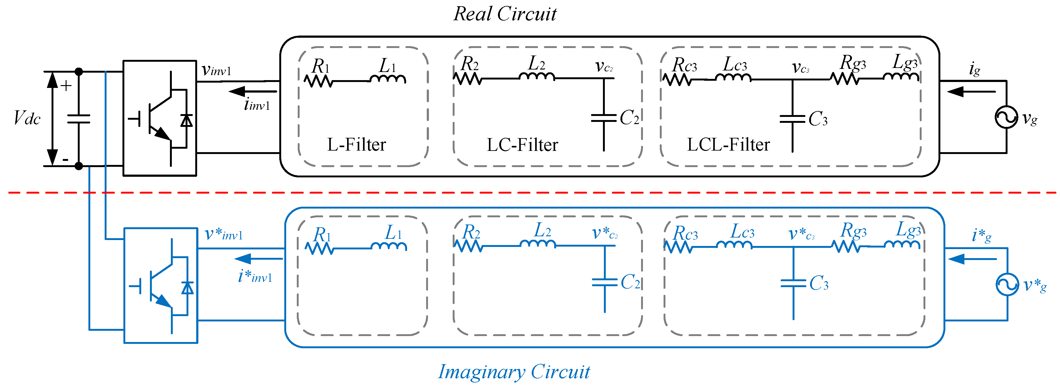
2.1. Single-Phase GCC

The upper half of Figure 1 shows the schematic of a single-phase GCC. A DC-link capacitor is on the left; a single-phase voltage source, standing for the grid voltage at the point of common coupling (PCC), is on the right; and an output filter is placed in the middle [2,3]. The output filter is used to reduce the harmonics to the utility grid. Three basic types of filters include [32]: the L filter, the LC filter and the LCL filter (Figure 1).

2.2. Imaginary Circuit

To implement d-qvector control, an imaginary orthogonal circuit (the lower half of Figure 1) needs to be created based on the real circuit of the GCC. The imaginary circuit should have exactly the same amplitude as the real circuit, but π / 2 phase shift. The real and imaginary circuits constitute the α - β frame of the GCC system, which then can be transferred into the d-q frame [7].

2.3. Mathematical Model in the d-q Frame

In the d-q frame, the mathematics model of an L filter-based single-phase GCC is Equation (1):
d d t i d i q = - R 1 / L 1 - ω s ω s R 1 / L 1 i d i q - 1 L 1 v d 1 - v d v q 1 - v q
For an LC filter-based GCC, the system equations are represented by Equations (2) and (3).
d d t i d 1 i q 1 = - R 2 / L 2 - ω s ω s R 2 / L 2 i d 1 i q 1 - 1 L 2 v d 1 - v d v q 1 - v q
i d i q = i d 1 i q 1 + 0 - C 2 ω s C 2 ω s 0 v d v q
Equation (4) describes the system equation of an LCL filter-based GCC [33].
d d t i d i q i d 1 i q 1 v c d v c q = - R g 3 L g 3 ω s 0 0 - 1 L g 3 0 - ω s - R g 3 L g 3 0 0 0 - 1 L g 3 0 0 - R c 3 L c 3 ω s 1 L c 3 0 0 0 - ω s - R c 3 L c 3 0 1 L c 3 1 C 3 0 - 1 C 3 0 0 ω s 0 1 C 3 0 - 1 C 3 - ω s 0 i d i q i d 1 i q 1 v c d v c q + 1 L g 3 0 0 0 0 0 0 1 L g 3 0 0 0 0 0 0 - 1 L c 3 0 0 0 0 0 0 - 1 L c 3 0 0 0 0 0 0 0 0 0 0 0 0 0 0 v d v q v d 1 v q 1 0 0
In Equations (1)–(4), ω s represents the angular frequency of the grid voltage; all other symbols are consistent with those specified in Figure 1. The corresponding relationships of all of the variables between the d-q domain and the single-phase circuit domain are the following: i g , i g * i d , i q , i i n v 1 , i i n v 1 * i d 1 , i q 1 , v g , v g * v d , v q , v i n v 1 , v i n v 1 * v d 1 , v q 1 and v c 3 , v c 3 * v c d , v c q .

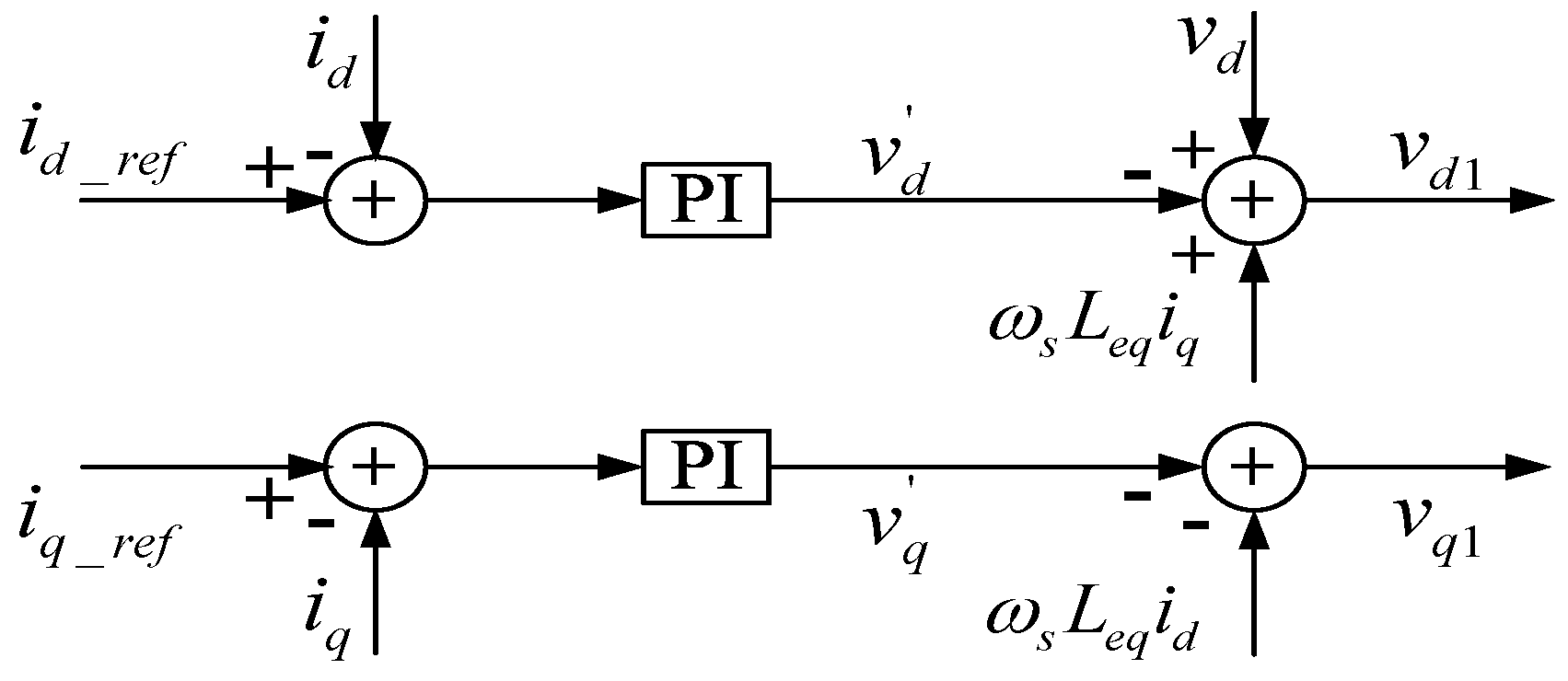
2.4. Conventional Decoupled Vector Control

2.4.1. The Single-Phase L Filter GCC

The conventional vector control method for a single-phase L filter GCC is the same as that for a three-phase L filter GCC [7]. The controller design [10] for the current loop is developed by rewriting Equation (1) as:
v d 1 = - ( R 1 i d + L 1 d i d d t ) v d + ω s L 1 i q + v d
v q 1 = - ( R 1 i q + L 1 d i q d t ) v q - ω s L 1 i d
in which those items denoted as v d and v q are treated as the state equations between the input voltages and output currents for the d- and q-axis current loops, with the other terms regarded as compensation items, which are normally omitted in designing or tuning a convectional vector controller. The current-loop controller is designed based on the corresponding transfer function 1 / ( R 1 + L 1 s ) [5].

2.4.2. The Single-Phase LC Filter and LCL Filter GCC

For a single-phase GCC with an LC filter or LCL filter, one possible vector control policy is to omit the capacitance and to simplify the system into the corresponding L filter system [5]. Thus, the vector control approach for an LC filter or LCL filter system takes exactly the same policy as that for an L filter system. This additional approximation would further increase the decoupling inaccuracy issue.
The controller design of the current loop is developed based on Equations (7) and (8), in which, for the LC filter system, R eq = R 2 and L eq = L 2 ; for the LCL filter system, R eq = R c 3 + R g 3 and L eq = L c 3 + L g 3 .
v d 1 = - ( R eq i d + L eq d i d d t ) v d + ω s L eq i q + v d
v q 1 = - ( R eq i q + L eq d i q d t ) v q - ω s L eq i d
However, this simplification would result in an imprecise description of the system and potential oscillatory and/or unstable dynamic behavior if the LC/LCL filter or the controller is not properly damped [6,10]. Figure 2 illustrates the common conventional decoupled vector control configuration for L, LC and LCL filter-based single-phase GCCs. In Figure 2, L eq equals L 1 , L 2 and L c 3 + L g 3 , respectively, for L, LC and LCL filter-based GCC controllers.

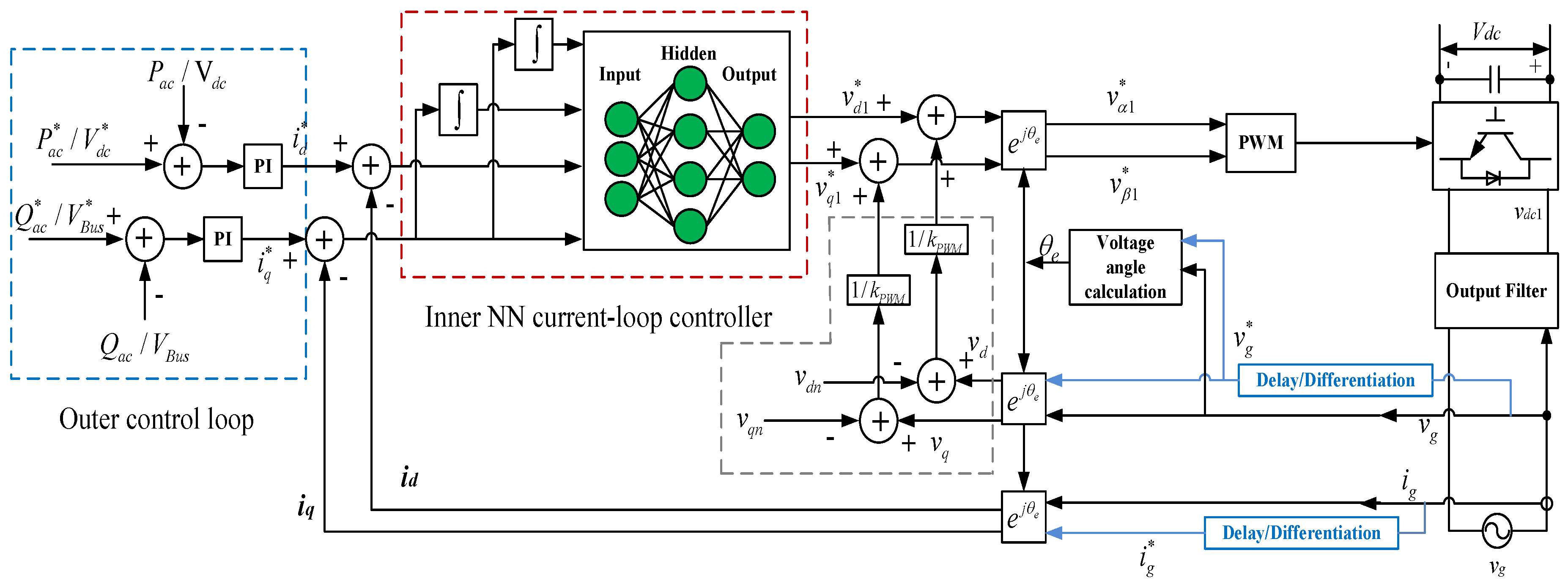
3. Novel Neural Network Vector Control

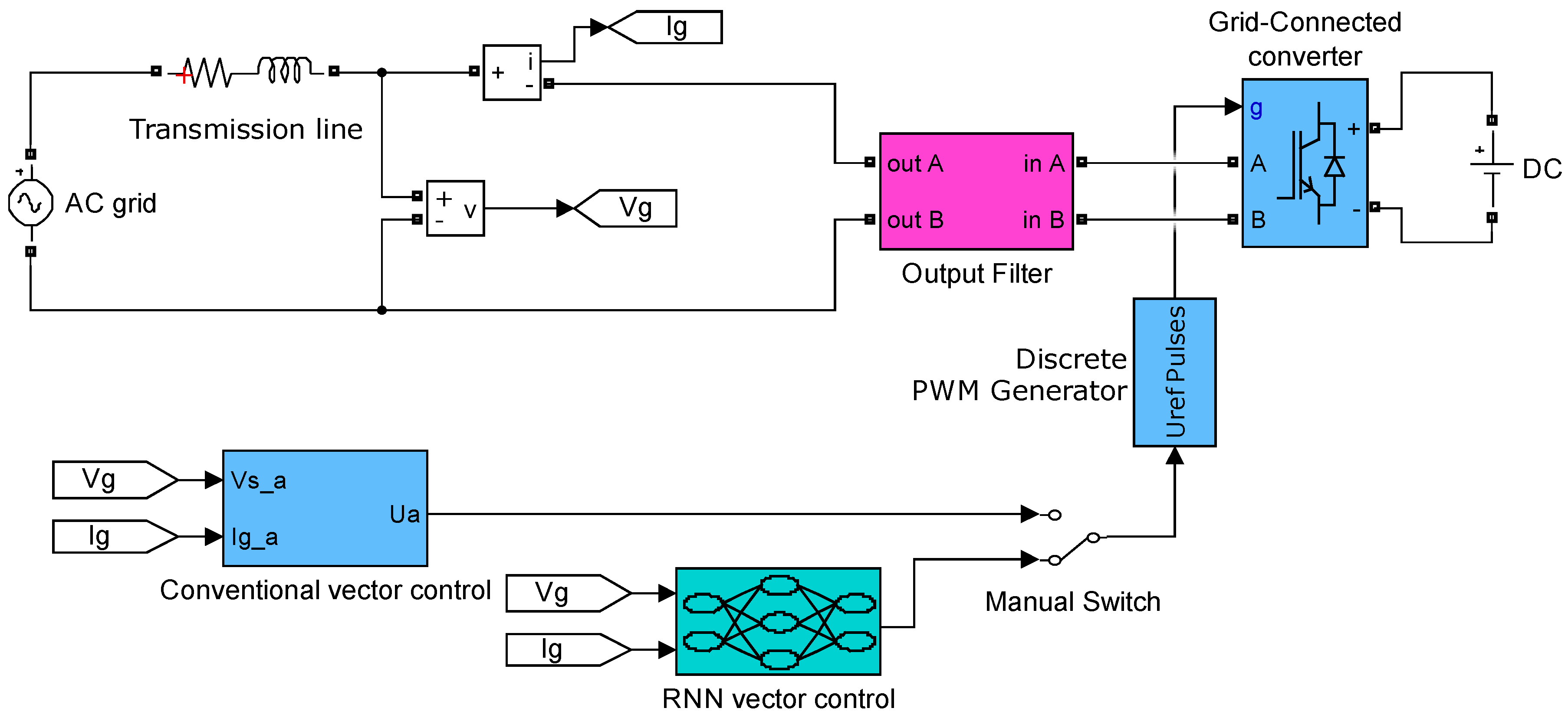
3.1. Neural Network Vector Control Architecture

Figure 3 demonstrates the proposed neural network vector control architecture for a single-phase GCC. The nested-loop controller consists of a slow outer loop and a fast inner loop [34,35]. The neural network plays the role of the inner current-loop controller. The outer control loops still utilize PI controllers. Under the PCC voltage-oriented frame [10], the d-axis loop is for active power or DC-link voltage control, and the q-axis loop is used for reactive power or grid voltage support control.
In Figure 3, v d c 1 stands for the converter output voltage. v g and v g * are the single-phase PCC voltage and created imaginary single-phase PCC voltage, respectively, and their corresponding voltages in the d-q domain v d and v q . i g and i g * stand for the single-phase current and created imaginary single-phase current, respectively, flowing, and their corresponding currents in the d-q domain are i d and i q . v d 1 * and v q 1 * are d- and q-axis control voltages from the NN outputs.
For the single-phase GCC system with three different kinds of filters, the same NN vector control architecture was proposed. The controller will be trained based on complete system dynamic equations and without using any special decoupling policies or damping methods. For all three filtering schemes, the controller just needs measured grid current, grid voltage and DC-link voltage to achieve the closed-loop current control, which would make it convenient to implement the NN vector control in real-life conditions.

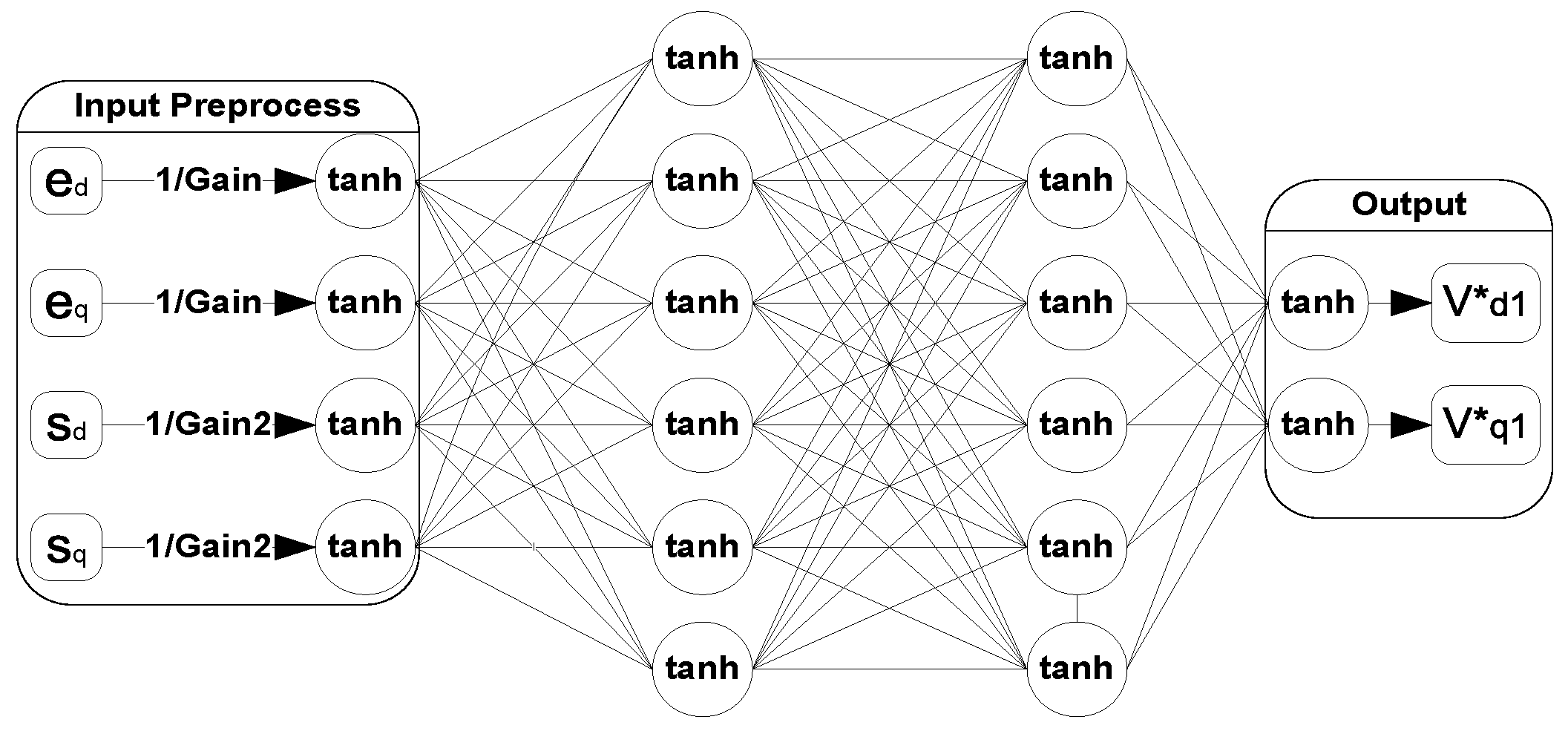
3.2. Neural Network Controller Structure

Figure 4 shows the proposed current-loop NN controller, which contains two parts: an input preprocessing block and a four-layer feed-forward neural network. The inputs are first regulated into the range [−1, 1] through a preprocessing procedure to avoid input saturation. The feed-forward neural network takes tanh ( e d q / G a i n ) and tanh ( s d q / G a i n 2 ) as inputs, where e d q and s d q are error terms and the integrals of the error terms. e d q is defined as e d q ( k ) = i d q ( k ) - i d q _ r e f ( k ) , and s d q ( k ) is calculated by:
s d q ( k ) = 0 k T s e d q ( t ) d t T s j = 1 k e d q ( j - 1 ) + e d q ( j ) 2
in which e d q ( 0 ) 0 and the trapezoid formula was used to compute the integral term s d q ( k ) .
The feed-forward NN contains two hidden layers, and each hidden layer has six nodes. The output layer has two nodes, which generates two d-q voltage control signals. The hyperbolic tangent functions are used as transfer functions at all nodes. Two hidden layers generally yield a stronger approximation ability [36]. The selection of the number of neurons in each hidden layer was done through trial and error tests [30].
The proposed NN controller in Figure 3 actually is a recurrent neural network (RNN) because the feedback signal of the system acts as a recurrent connection for the NN from the output back to the input, though the feed-forward NN does not have a clear feedback weight.
According to Figure 4, the NN controller, denoted as R ( e d q , s d q , w ) , is a function of e d q , s d q and network weights w . Because the ratio of the converter output voltage v d q 1 to the outputs of the current loop controller v d q 1 * is the gain of the pulse-width-modulation (PWM), which is denoted as k P W M [37], the control action v d q 1 can be expressed as:
v d q 1 = k PWM v d q 1 * = k PWM R ( e d q , s d q , w )
To prevent the NN controller from the affection of the GCC voltage variation, the PCC disturbance voltage is introduced to the output of a well-trained neural network [29].
v d q 1 = k PWM R ( e d q , s d q , w ) + ( v d q n - v d q ) / k PWM
where v d q n is nominal PCC voltage and v d q is the actual PCC voltage. The PCC disturbance voltage can calculated by ( v d q n - v d q ). The implementation of Formula (11) is circled by the grey dashed lines in Figure 4, in which v d q n = [ v d n , v q n ] and v d q = [ v d , v q ] .

4. Training Neural Network Controller

4.1. Training Objective: Approximate Optimal Control

Dynamic programming (DP) employs the principle of Bellman’s optimality [23] and can serve as a great tool for solving optimal control problems [25].
We define the DP cost function for the NN training as:
C d p = k = j γ k - j U ( e d q ( k ) ) = k = j γ k - j [ i d ( k ) - i d _ ref ( k ) ] 2 + [ i q ( k ) - i q _ ref ( k ) ] 2
where γ is a discount factor with 0 < γ ≤ 1 and U is called the local cost or utility function. The cost function C d p is referred to as the cost-to-go of state i d q ( j ) , which depends on the initial time j > 0 and the initial state i d q ( j ) . The purpose of the NN training is to find the optimal weights, so that the DP cost C d p in Equation (12) is minimized.

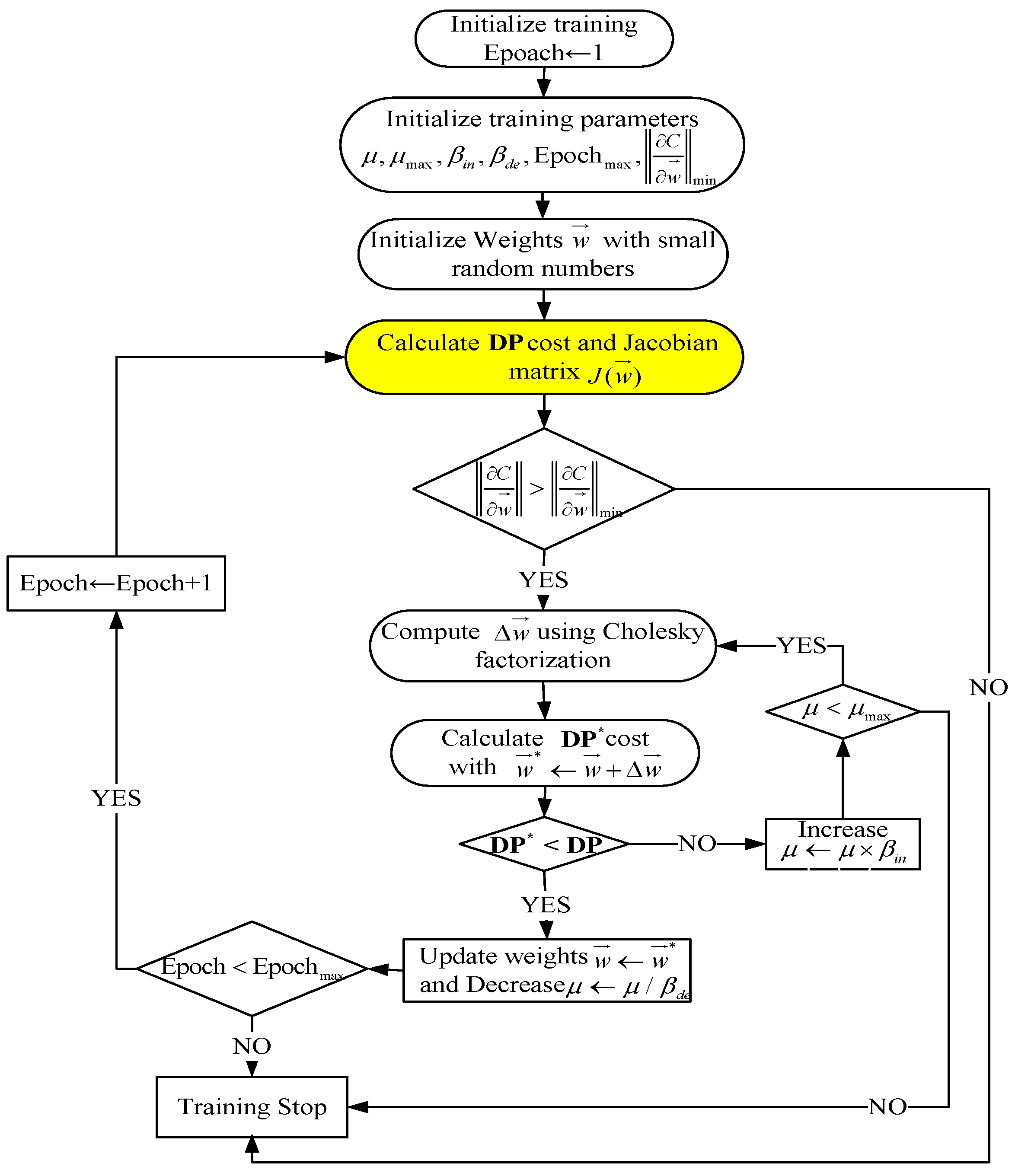
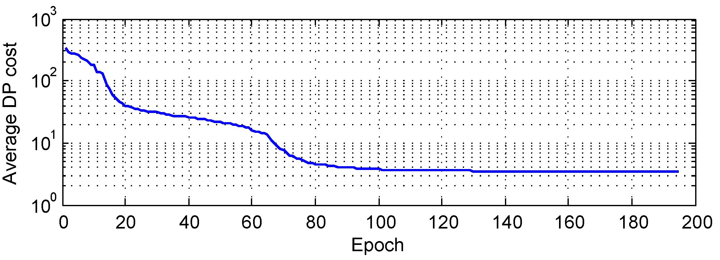
4.2. NN Training Algorithm: Levenberg–Marquardt

The Levenberg–Marquardt (LM) algorithm appears to be the fastest neural network training algorithm for a moderate number of network parameters [38], and also, LM usually can achieve better convergency performance than Backpropagation through time (BPTT) algorithm in training the recurrent neural network [39]. Therefore, the LM algorithm was used to train the NN controller for single-phase GCCs.
The LM algorithm requires that the cost function defined in Equation (12) be rewritten in a sum-of-squares form. The cost function C d p with γ = 1 , j = 1 and k = 1 , , N (N stands for the trajectory length) can be reformed as:
C d p = k = 1 N U ( e d q ( k ) ) def V ( k ) = U ( e d q ( k ) ) C d p = k = 1 N V 2 ( k )
and the gradient C d p w can be written in a matrix product form:
C d p w = k = 1 N V ( k ) V ( k ) w = 2 J v ( w ) T V
where the Jacobian matrix J v ( w ) is:
J v ( w ) = V ( 1 ) w 1 V ( 1 ) w M V ( N ) w 1 V ( N ) w M , V = V ( 1 ) V ( N )
The weights update formula [38,40,41] for a NN controller can be expressed as:
w = - [ J v ( w ) T J v ( w ) + μ I ] - 1 J v ( w ) T V
For a GCC system with an L, LC or LCL filter, the calculation of Jacobian matrix J v ( w ) needs to pass through the corresponding system dynamic equations, e.g., Equation (1) for the L filter, Equations (2) and (3) for the LC filter and Equation (4) for the LCL filter, which is the main difference in implementing the training process of the proposed NN vector control for the three different filtering schemes. The works in [30,39] illustrate the efficient forward accumulation through time (FATT) algorithm used to calculate J v ( w ) for the L filter- and the LCL filter-based GCCs, respectively. The training process for an LC filter-based GCC is similar to that for an LCL filter-based GCC because the LC filter could be considered as a special case of an LCL filter in calculating the J v ( w ) .
Figure 5 demonstrates that the LM algorithm dynamically adjusts μ to ensure that the DP cost function keeps decreasing [36,38]. The difference in training an NN controller for an L, LC and LCL filter-based GCC only exists in the box highlighted in yellow in Figure 5, which is the calculation of the Jacobian matrix as explained above. In Figure 5, μ max , β de , β in , Epoch max and C d p / w min stand for maximum μ , the decreasing and increasing factors, the maximum number of training epochs and the norm of the minimum gradient, respectively. The initial μ is set as 0.001, β de = 0.1, and β in = 10 [36]. The Cholesky factorization was used to calculate the weights update in Equation (16), which is roughly twice as efficient as the Lower-Upper (LU) decomposition for solving systems of linear equations [42]. The training stops when: (1) the training epoch reaches a maximum value Epoch max ; (2) μ is larger than μ max ; or (3) the gradient is smaller than the predefined minimum value C d p / w min . In our training process, Epoch max was set as 200; μ max was selected as 1 × 10 10 ; and C d p / w min was chosen as 1 × 10 - 10 .

4.3. Training Implementation

Table 1 specifies the parameters of a single-phase GCC system. Most system parameters are from [43,44]; the capacitor values were selected as 20 μ F to provide better attenuation results. Figure 6 compares the frequency response of three different filters corresponding to harmonic currents injected into the grid, in which the peaks stand for resonant frequencies.
The average DP cost per trajectory shown in Figure 7 drops to a small value very quickly within 100 iterations and then stabilizes at this value, demonstrating a good convergence result of the LM training algorithm.

5. Performance Evaluation

To evaluate the tracking performance of the NN controller and to compare it to conventional vector controllers, the integrated transient simulation systems were developed for all three filter schemes based single-phase GCC systems using the MATLAB SimPowerSystems toolbox. Figure 8 gives an example of a single-phase GCC Simulink model with the output filter.
For the conventional vector control method, the current-loop PI controller was tuned by the PID tuner function within the PID controller block in MATLAB as shown in Figure 9. For L filter GCC, R eq = R 1 and L eq = L 1 . For LC filter GCC and LCL filter GCC, R eq and L eq follow the analysis in Section 2.4.2. The phase margin was set as 60 deg, and the bandwidth was chosen as 1500 rad/s, which tends to yield the best results considering the PWM saturation constraints. As R eq and L eq take the same value for the three different kinds of filters analyzed in this paper, the conventional controller for all three filtering schemes uses the same PI parameters to control a GCC. For all simulations of Section 5, T s = 0.1 ms was used if not specified. Switching frequency f s = 6000 Hz was chosen according to the frequency response plot shown in Figure 6.

5.1. L Filter-Based GCC

With the imaginary circuit created by using the delay method, both conventional and NN vector control approaches showed similar performance in Figure 10a,b. However, lower overshoot was observed from the corresponding single-phase PCC current at t = 1 s under the NN vector control (Figure 10d) compared to the conventional vector control (Figure 10c).
With the imaginary circuit created by using the differentiation method, the conventional vector control demonstrated a poor performance in Figure 11a: very large oscillations. This is due to the fact that the grid oscillations could cause inaccuracies of the imaginary circuit created by using the differentiation method. However, the NN vector control still performed very well in Figure 11b: less oscillations and lower overshoot.

5.2. LC Filter-Based GCC

Compared to conventional vector control Figure 12a,c for LC filter-based GCC, the NN vector control showed good tracking ability (Figure 12b,d), as expected, such as lower overshoot and faster response speed. The NN vector control seems to be able to combine fast response speed and low overshoot together and provide good performance to approximate optimal control.

5.3. LCL Filter-Based GCC

To overcome the resonance phenomenon of the LCL filter, the passive damping method was adopted in developing conventional vector control [45]. The resonance frequency can be calculated using Equation (17) [46].
f r = 1 2 π L g + L c L g L c C
Thus, a series resistors was chosen as R p d = 7.71 Ω according to Equation (18) [5]:
R p d = 1 3 ( 1 C ω r ) = 1 3 ( 1 C 2 π f r )
The NN-based vector control is a damping free approach, i.e., it does not require any special damping policies, which is needed for conventional vector control. Figure 12b and Figure 13d demonstrate that the NN vector control still performed better than conventional vector control for the LCL filter-based GCC under no damping condition.
Another feature is that the sampling rate for the NN vector control is T s = 1 ms, while for conventional vector control, it has to be 0.1 ms to assure the stable operation of the controller.

6. Hardware Experiment Validation

6.1. Experiment Setup

To validate the proposed NN vector control approach, a hardware-in-the-loop test system for a single-phase GCC in an AC/DC/DC converter application was built. This converter configuration is widely used in solar photovoltaic systems. Figure 14 demonstrates an example of the AC/DC/DC converter, in which the left-side power source represents the grid and the right-side stands for a renewable energy source (RES), e.g., a solar panel or array.
The hardware setups are as follows: (1) an AC/DC converter was connected to a variable single-phase AC power supply using LabVolt [47] standing for the grid; (2) an adjustable single-phase DC power supply standing for an RES was connected to a DC/DC converter; (3) all of the filters were built using LabVolt smoothing inductors and capacitors; (4) a dSPACE digital control system controlled the the AC/DC converter and sent out the control signals [48].
Figure 15 demonstrates an example of the AC/DC/DC converter experiment with an L filter.
Table 2 specifies all of the experiments’ parameters. The damping resistor for the LCL filter is R p d + R C i n = 25 Ω for conventional vector control. The NN controller was retrained based on Table 2. The sampling time T s = 0.1 ms was used for all hardware experiments.
The power balance principle is used to develop the DC-link voltage controller, and its corresponding plant transfer function V d V d c C · s was utilized to tune the PI controller [34,49]. The tuning process for the voltage loop is the same as that for the current loop described in Section 5. Unlike the fast inner current loop, the voltage loop must be slow because it takes time to charge the capacitor [50]. For the voltage controller, the phase margin was set as 60 deg, and the bandwidth was chosen as 4 rad/s. In our experiments, any bandwidth larger than 4 rad/s failed to maintain the DC-link voltage constant when using the conventional vector control. For NN vector control, a relatively faster voltage-loop controller was adopted with its bandwidth selected as 8 rad/s due to the good current tracking ability.

6.2. Experiment Results

The test sequence was scheduled as the following. With t = 0 s as the starting point for data recording: around t = 40 s, there was an increase of the generating reactive demand, which corresponds to an increase of the q-axis current; around t = 100 s, the reactive power reference changes from generating to absorbing, which corresponds to a decrease of the q-axis current; around t = 120 s, there was a random change of the active power transferred from the RES converter to the DC-link capacitor representing the power generated from the solar panels; around t = 220 s, the random change of the active power was ended.

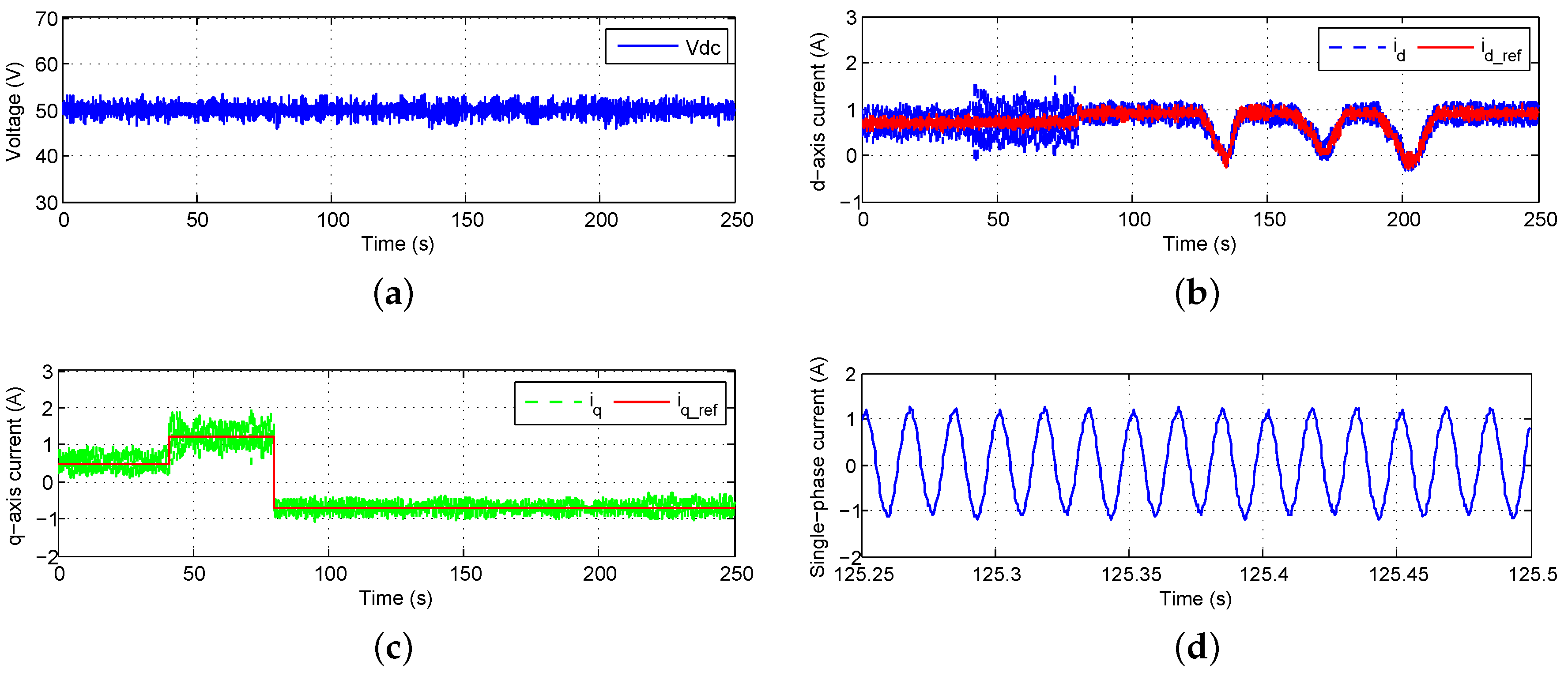
6.2.1. L Filter-Based GCC

Figure 16 shows the experiment results of the AC/DC/DC converter with an L filter under the conventional vector control, and Figure 17 shows the corresponding results under the NN vector control. Whenever there was a change in i q _ ref (Figure 16c), an obvious voltage overshoot was seen from the DC-link voltage waveform under the conventional vector control (Figure 16a). However, when using the NN vector control, no overshoot was observed (Figure 17a) even for a larger variation of i q _ ref (Figure 17c). In fact, under i q _ ref = −0.7 A condition, the NN vector control can still maintain DC-link voltage, while the conventional vector control failed in this i q _ ref reference current.
During the random changing period as shown by Figure 16b, the dc-link voltage showed large oscillations using the conventional vector control (Figure 16a). However, the NN vector control can still maintain the DC-link voltage at the reference voltage very well (Figure 17a,b).
The current waveform further demonstrated the advantage of the NN vector control. The single-phase current showed much less oscillations under the NN vector control (Figure 17d) than under the conventional vector control (Figure 16d).
Note that the NN vector control results (Figure 17) were obtained under a low switching frequency f s = 1980 Hz, while the conventional vector control results (Figure 16) were obtained under a switching frequency f s = 3000 Hz. We found that the distortion was even worse for the conventional vector control if the switching frequency is 1980 Hz. Only when the switching frequency was increased to 6000 Hz, the conventional vector control can achieve a performance close to that of NN vector control. However, conventional vector control using a high frequency could cause more power loss than NN vector control with low f s .

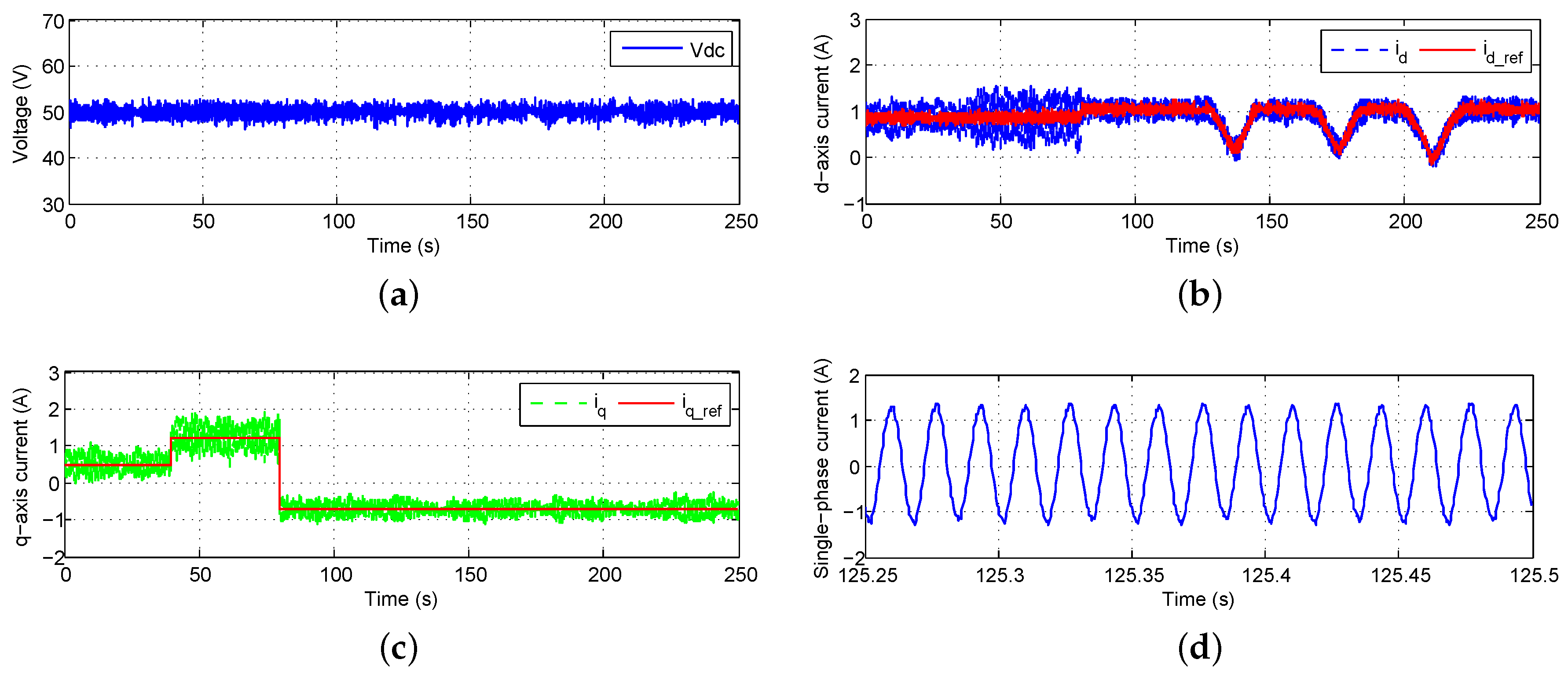
6.2.2. LC Filter-Based GCC

Figure 18 demonstrates the experiment results of the AC/DC/DC converter with an LC filter by using the NN vector control method. The system with the LC filter showed less oscillations in the DC-link voltage and much improved power quality (Figure 18a) than that with the L filter (Figure 17a).

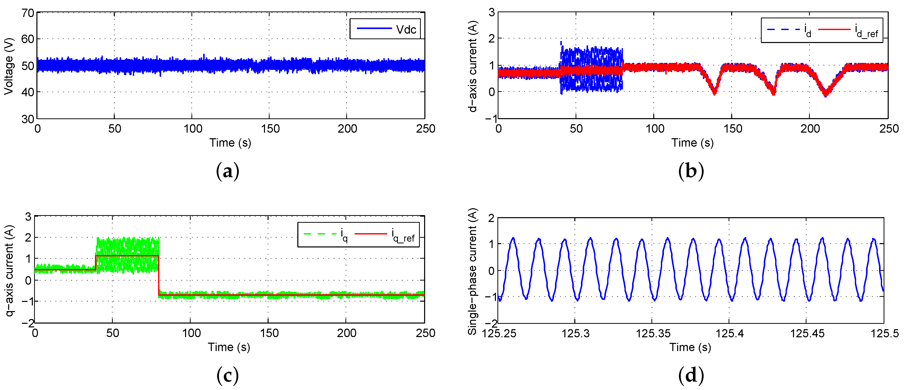
6.2.3. LCL Filter-Based GCC

Figure 19 demonstrates the experiment results of the AC/DC/DC converter with an LCL filter by using the NN vector control method. For the LCL filter-based system, the overall performance is even better (Figure 19a).
However, for the LC filter- or LCL filter-based system, the conventional vector control method will lose stability without proper damping policies. After certain damping policies were used, the conventional vector control method still failed to provide good performance in the AC/DC/DC converter experiments.
In the lab experiment setups, the system contains much noise, e.g., measurement noise from sensors. Further, the distorted grid voltage increases the control difficulty. However, in general, the NN vector control showed very good performance for the AC/DC/DC converter with all three different filtering schemes, demonstrating the great advantage of the neural network vector control over the conventional vector control.

7. Conclusions

The paper proposed a common NN vector control structure for the single-phase GCC system no matter what kind of filter is used, which simplifies the controller design and real-life implementation. In both the simulation evaluation and hardware experiments, the neural network control technique has demonstrated superior performance to the conventional control approach, e.g., faster response time, lower overshoot and less oscillation. The NN control overcomes the decoupling inaccuracy associated with designing conventional vector controllers for GCC systems. Especially, for single-phase GCC with an LCL filter, the neural network vector control does not require any damping policy. The NN vector control technique significantly reduces the harmonics and benefits the integration of small-scale renewable resources to the grid.
The paper also studied two different methods to generate the imaginary circuit. Although the control performance of conventional vector control methods is more sensitive to how the imaginary circuit is created, the neural network vector control is not affected by this problem and performs very well in general. The success of the hardware experiments validates the feasibility to implement the proposed NN control for single-phase inverters in real-life conditions.

Acknowledgments

This work was supported in part by the U.S. National Science Foundation under Grant 1414379.

Author Contributions

Both authors contributed equally to this manuscript.

Conflicts of Interest

The authors declare no conflict of interest.

References

  1. Senturk, O.S.; Helle, L.; Munk-Nielsen, S.; Rodriguez, P.; Teodorescu, R. Power Capability Investigation Based on Electrothermal Models of Press-Pack IGBT Three-Level NPC and ANPC VSCs for Multimegawatt Wind Turbines. IEEE Trans. Power Electron. 2012, 27, 3195–3206. [Google Scholar] [CrossRef]
  2. Wu, W.; Sun, Y.; Lin, Z.; Tang, T.; Blaabjerg, F.; Chung, H.S. A New LCL-Filter With In-Series Parallel Resonant Circuit for Single-Phase Grid-Tied Inverter. IEEE Trans. Ind. Electron. 2014, 61, 4640–4644. [Google Scholar] [CrossRef]
  3. Kjaer, S.B.; Pedersen, J.K.; Blaabjerg, F. Linear Current Control Scheme With Series Resonant Harmonic Compensator for Single-Phase Grid-Connected Photovoltaic Inverters. IEEE Trans. Ind. Electron. 2008, 55, 1292–1306. [Google Scholar]
  4. Hornik, T.; Zhong, Q.C. A Current-Control Strategy for Voltage-Source Inverters in Microgrids Based on H∞ and Repetitive Control. IEEE Trans. Power Electron. 2011, 26, 943–952. [Google Scholar] [CrossRef]
  5. Liserre, M.; Blaabjerg, F.; Hansen, S. Design and control of an LCL filter-based three-phase active rectifier. IEEE Trans. Ind. Appl. 2005, 41, 1281–1291. [Google Scholar] [CrossRef]
  6. Blasko, V.; Kaura, V. A Novel Control to Actively Damp Resonance in Input LC Filter of a Three-Phase Voltage Source Converter. IEEE Trans. Ind. Appl. 1997, 33, 542–550. [Google Scholar] [CrossRef]
  7. Zhang, R.; Cardinal, M.; Szczesny, P.; Dame, M. A grid simulator with control of single-phase power converters in D-Q rotating frame. In Proceedings of the IEEE Power Electronics Specialists Conference, Cairns, QLD, Australia, 23–27 June 2002; pp. 1431–1436.
  8. Roshan, A.; Burgos, R.; Baisden, A.C.; Wang, F.; Boroyevich, D. A D-Q Frame Controller for a Full-Bridge Single Phase Inverter Used in Small Distributed Power Generation Systems. In Proceedings of the IEEE Applied Power Electronics Conference, Anaheim, CA, USA, 25 February–1 March 2007; pp. 641–647.
  9. Bahrani, B.; Rufer, A.; Kenzelmann, S.; Lopes, L.A.C. Vector Control of Single-Phase Voltage-Source Converters Based on Fictive-Axis Emulation. IEEE Trans. Ind. Appl. 2011, 47, 831–840. [Google Scholar] [CrossRef]
  10. Dannehl, J.; Wessels, C.; Fuchs, F.W. Limitations of Voltage-Oriented PI Current Control of Grid-Connected PWM Rectifiers With LCL Filters. IEEE Trans. Ind. Electron. 2009, 56, 380–388. [Google Scholar] [CrossRef]
  11. Saitou, M.; Shimizu, T. Generalized Theory of Instantaneous Active and Reactive Powers in Single-phase Circuits based on Hilbert Transform. In Proceedings of the Power Electronics Specialists Conference, Cairns, QLD, Australia, 23–27 June 2002; pp. 1419–1424.
  12. Khadkikar, V.; Chandra, A.; Singh, B.N. Generalised single-phase p-q theory for active power filtering: Simulation and DSP-based experimental investigation. IET Power Electron. 2009, 2, 67–78. [Google Scholar] [CrossRef]
  13. Dasgupta, S.; Sahoo, S.K.; Panda, S.K. Single-Phase Inverter Control Techniques for Interfacing Renewable Energy Sources With Microgrid-Part I: Parallel-Connected Inverter Topology With Active and Reactive Power Flow Control Along With Grid Current Shaping. IEEE Trans. Power Electron. 2011, 26, 717–731. [Google Scholar] [CrossRef]
  14. Dasgupta, S.; Sahoo, S.K.; Panda, S.K. Single-Phase Inverter Control Techniques for Interfacing Renewable Energy Sources With Microgrid-Part II: Series-Connected Inverter Topology to Mitigate Voltage-Related Problems Along With Active Power Flow Control. IEEE Trans. Power Electron. 2011, 26, 732–746. [Google Scholar] [CrossRef]
  15. Czarnecki, L.S. Comparison of instantaneous reactive power p-q theory with theory of the current’s physical components. Electr. Eng. 2003, 85, 21–28. [Google Scholar]
  16. Czarnecki, L.S. Instantaneous Reactive Power p-q Theory and Power Properties of Three-Phase Systems. IEEE Trans. Power Deliv. 2006, 21, 362–367. [Google Scholar] [CrossRef]
  17. Dasgupta, S.; Sahoo, S.K.; Panda, S.K. A Robust Predictive Current Control for Three-Phase Grid-Connected Inverters. IEEE Trans. Ind. Electron. 2009, 56, 1993–2004. [Google Scholar]
  18. Zhang, N.; Tang, H.; Yao, C. A Systematic Method for Designing a PR Controller and Active Damping of the LCL Filter for Single-Phase Grid-Connected PV Inverters. Energies 2014, 7, 3934–3954. [Google Scholar] [CrossRef]
  19. Yepes, A.G.; Freijedo, F.D.; Doval-Gandoy, J. On the discrete-time implementation of resonant controllers for active power filters. In Proceedings of the 35th Annual Conference IEEE Industrial Electronics, Porto, Portugal, 3–5 November 2009; pp. 3686–3691.
  20. Abrishamifar, A.; Ahmad, A.A.; Mohamadian, M. Fixed Switching Frequency Sliding Mode Control for Single-Phase Unipolar Inverters. IEEE Trans. Power Electron. 2012, 27, 2507–2514. [Google Scholar] [CrossRef]
  21. Komurcugil, H.; Ozdemir, S.; Sefa, I.; Altin, N.; Kukrer, O. Sliding-Mode Control for Single-Phase Grid-Connected LCL-Filtered VSI With Double-Band Hysteresis Scheme. IEEE Trans. Ind. Electron. 2016, 63, 864–873. [Google Scholar] [CrossRef]
  22. Hao, X.; Yang, X.; Liu, T.; Huang, L.; Chen, W. A Sliding-Mode Controller With Multiresonant Sliding Surface for Single-Phase Grid-Connected VSI With an LCL Filter. IEEE Trans. Power Electron. 2013, 28, 2259–2268. [Google Scholar] [CrossRef]
  23. Bellman, R.E. Dynamic Programming; Princeton University Press: Princeton, NJ, USA, 1957. [Google Scholar]
  24. Balakrishnan, S.N.; Biega, V. Adaptive-Critic-Based Neural Networks for Aircraft Optimal Control. J. Guid. Control Dyn. 1996, 19, 893–898. [Google Scholar] [CrossRef]
  25. Prokhorov, D.V.; Wunsch, D.C. Adaptive Critic Designs. IEEE Trans. Neural Netw. 1997, 8, 997–1007. [Google Scholar] [CrossRef] [PubMed]
  26. Wang, F.; Zhang, H.; Liu, D. Adaptive dynamic programming: An introduction. IEEE Comput. Intell. Mag. 2009, 4, 39–47. [Google Scholar] [CrossRef]
  27. Venayagamoorthy, G.K.; Harley, R.G.; Wunsch, D.C. Comparison of Heuristic Dynamic Programming and Dual Heuristic Programming Adaptive Critics for Neurocontrol of a Turbogenerator. IEEE Trans. Neural Netw. 2002, 13, 764–773. [Google Scholar] [CrossRef] [PubMed]
  28. Li, S.; Fairbank, M.; Wunsch, D.C.; Alonso, E. Vector Control of a Grid-Connected Rectifier/Inverter Using an Artificial Neural Network. In Proceedings of the IEEE World Congress on Computational Intelligence, Brisbane, Australia, 10–15 June 2012; pp. 1–7.
  29. Li, S.; Fairbank, M.; Johnson, C.; Wunsch, D.C.; Alonso, E.; Proaño, J.L. Artificial Neural Networks for Control of a Grid-Connected Rectifier/Inverter Under Disturbance, Dynamic and Power Converter Switching Conditions. IEEE Trans. Neural Netw. Learn. Syst. 2014, 25, 738–750. [Google Scholar] [PubMed]
  30. Fu, X.; Li, S.; Jaithwa, I. Implement Optimal Vector Control for LCL-Filter-Based Grid-Connected Converters by Using Recurrent Neural Networks. IEEE Trans. Ind. Electron. 2015, 62, 4443–4454. [Google Scholar] [CrossRef]
  31. Fu, X.; Li, S. Control of Single-Phase Grid-Connected Converters with LCL Filters Using Recurrent Neural Network and Conventional Control Methods. IEEE Trans. Power Electron. 2016, 31, 5354–5364. [Google Scholar] [CrossRef]
  32. Lettl, J.; Bauer, J.; Linhart, L. Comparison of Different Filter Types for Grid Connected Inverter. In Proceedings of the Progress In Electromagnetics Research Symposium (PIERS), Marrakesh, Morocco, 20–23 March 2011; pp. 1426–1429.
  33. Teodorescu, R.; Liserre, M.; Rodriguez, P. Grid Converters for Photovoltaic and Wind Power Systems; John Wiley and Sons: Chichester, UK, 2011. [Google Scholar]
  34. Li, S.; Haskew, T.A.; Hong, Y.K.; Xu, L. Direct-current vector control of three-phase grid-connected rectifier–inverter. Electr. Power Syst. Res. 2011, 81, 357–366. [Google Scholar] [CrossRef]
  35. Rocabert, J.; Azevedo, G.M.S.; Luna, A.; Guerrero, J.M.; Candela, J.I.; Rodriguez, P. Intelligent Connection Agent for Three-Phase Grid-Connected Microgrids. IEEE Trans. Power Electron. 2011, 26, 2993–3005. [Google Scholar] [CrossRef]
  36. Hagan, M.T.; Demuth, H.B.; Beale, M.H. Neural Network Design; PWS Publishing: Boston, MA, USA, 2002. [Google Scholar]
  37. Mohan, N.; Undeland, T.M.; Robbins, W.P. Power Electronics: Converters, Applications, and Design, 3rd ed.; John Wiley and Sons: Chichester, UK, 2002. [Google Scholar]
  38. Hagan, M.T.; Menhaj, M.B. Training Feedforward Networks with the Marquardt Algorithm. IEEE Trans. Neural Netw. 1994, 5, 989–993. [Google Scholar] [CrossRef] [PubMed]
  39. Fu, X.; Li, S.; Fairbank, M.; Wunsch, D.C.; Alonso, E. Training Recurrent Neural Networks with the Levenberg-Marquardt Algorithm for Optimal Control of a Grid-Connected Converter. IEEE Trans. Neural Netw. Learn. Syst. 2015, 26, 1900–1912. [Google Scholar] [CrossRef] [PubMed]
  40. Levenberg, K. A method for the solution of certain non-linear problems in least squares. Q. J. Appl. Math. 1994, 2, 164–168. [Google Scholar]
  41. Marquardt, D.W. An Algorithm for Least-Squares Estimation of Nonlinear Parameters. J. Soc. Ind. Appl. Math. 1963, 11, 431–441. [Google Scholar] [CrossRef]
  42. Press, W.H.; Flannery, B.P.; Teukolsky, S.A.; Vetterling, W.T. Numerical Recipes in C: The Art of Scientific Computing; Cambridge University Press: New York, NY, USA, 1992. [Google Scholar]
  43. Castilla, M.; Miret, J.; Matas, J.; De Vicuña, L.G.; Guerrero, J.M. A Review of Single-Phase Grid-Connected Inverters for Photovoltaic Modules. IEEE Trans. Ind. Appl. 2005, 41, 4492–4501. [Google Scholar]
  44. Castilla, M.; Miret, J.; Matas, J.; De Vicuña, L.G.; Guerrero, J.M. Control Design Guidelines for Single-Phase Grid-Connected Photovoltaic Inverters With Damped Resonant Harmonic Compensators. IEEE Trans. Ind. Electron. 2009, 56, 4492–4501. [Google Scholar] [CrossRef]
  45. Peña-Alzola, R.; Liserre, M.; Blaabjerg, F.; Sebastián, R.; Dannehl, J.; Fuchs, F.W. Analysis of the Passive Damping Losses in LCL-Filter-Based Grid Converters. IEEE Trans. Power Electron. 2013, 28, 2642–2646. [Google Scholar] [CrossRef]
  46. Jalili, K.; Bernet, S. Design of LCL filters of active-front-end two level voltage-source converters. IEEE Trans. Ind. Electron. 2009, 56, 1674–1689. [Google Scholar] [CrossRef]
  47. Festo Didactic Inc. Available online: https://www.labvolt.com/ (accessed on 12 February 2016).
  48. dSPACE Inc. Available online: http://www.dspace.com/ (accessed on 12 February 2016).
  49. Mullane, A.; Lightbody, G.; Yacamini, R. Wind-Turbine Fault Ride-Through Enhancement. IEEE Trans. Power Syst. 2005, 20, 1929–1937. [Google Scholar] [CrossRef]
  50. Luo, A.; Tang, C.; Shuai, Z.; Tang, J.; Xu, X.Y.; Chen, D. Fuzzy-PI-Based Direct-Output-Voltage Control Strategy for the STATCOM Used in Utility Distribution Systems. IEEE Trans. Ind. Electron. 2009, 56, 2401–2411. [Google Scholar] [CrossRef]
Figure 1. The schematic of a single-phase grid-connected converter (GCC): real circuit and imaginary circuit.
Energies 09 00328 g001
Figure 2. Conventional decoupled vector control for simplified single-phase GCC with the L filter, the LC filter or the LCL filter.
Energies 09 00328 g002
Figure 3. Neural network vector control architecture for a single-phase GCC.
Energies 09 00328 g003
Figure 4. NN current-loop controller structure.
Energies 09 00328 g004
Figure 5. Levenberg–Marquardt (LM) algorithm for NN controller training.
Energies 09 00328 g005
Figure 6. Frequency response of three different filters.
Energies 09 00328 g006
Figure 7. Average dynamic programming (DP) cost per trajectory for training the neural controller.
Energies 09 00328 g007
Figure 8. Simulink models of the single-phase GCC with the output filter.
Energies 09 00328 g008
Figure 9. Block diagram for tuning the current-loop PI controller.
Energies 09 00328 g009
Figure 10. Comparisons for L filter-based GCC. (a) Conventional vector control: d-q currents; (b) NN vector control: d-q currents; (c) conventional vector control: single-phase current; (d) NN vector control: single-phase current.
Energies 09 00328 g010
Figure 11. Comparisons for L filter-based GCC with the imaginary circuit created by using the differentiation method. (a) Conventional vector control: d-q currents; (b) NN vector control: d-q currents.
Energies 09 00328 g011
Figure 12. Comparisons for LC filter-based GCC. (a) Conventional vector control: d-q currents; (b) NN vector control: d-q currents; (c) conventional vector control: single-phase current; (d) NN vector control: single-phase current.
Energies 09 00328 g012
Figure 13. Comparisons for LCL filter-based GCC. (a) Conventional vector control: d-q currents; (b) NN vector control: d-q currents; (c) conventional vector control: single-phase current; (d) NN vector control: single-phase current.
Energies 09 00328 g013
Figure 14. The AC/DC/DC converter experiment.
Energies 09 00328 g014
Figure 15. The hardware experiment testing system.
Energies 09 00328 g015
Figure 16. Conventional vector control for the AC/DC/DC converter with the L filter. (a) DC-link voltage; (b) point of common coupling (PCC) q-axis current waveform; (c) PCC q-axis current waveform; (d) single-phase current waveform.
Energies 09 00328 g016
Figure 17. NN vector control for the AC/DC/DC converter with the L filter. (a) DC-link voltage; (b) PCC q-axis current waveform; (c) PCC q-axis current waveform; (d) single-phase current waveform.
Energies 09 00328 g017
Figure 18. NN vector control for the AC/DC/DC converter with the LC filter. (a) DC-link voltage; (b) PCC q-axis current waveform; (c) PCC q-axis current waveform; (d) single-phase current waveform.
Energies 09 00328 g018
Figure 19. NN vector control for the AC/DC/DC converter with the LCL filter. (a) DC-link voltage; (b) PCC q-axis current waveform; (c) PCC q-axis current waveform; (d) single-phase current waveform.
Energies 09 00328 g019
Table 1. Single-phase GCC system parameters.
SymbolQuantityValueUnit
V g nominal grid voltage (rms)230V
fnominal grid frequency50Hz
V d c DC-link voltage500V
L 1 L filter inductor2.14mH
R 1 L filter resistor0.19Ω
L 2 LC filter inductor2.14mH
R 2 LC filter resistor0.19Ω
C 2 LC filter parallel capacitor20 μ F
L c 3 & L g 3 LCL filter inductor1.07mH
R c 3 & R g 3 LCL filter resistor0.095Ω
C 3 LCL filter parallel capacitor20 μ F
Table 2. The system parameters in the hardware experiment.
SymbolQuantityValueUnit
V g nominal grid voltage (rms)20V
fnominal grid frequency60Hz
V d c DC-link reference voltage50V
C d c DC-link capacitance3260 μ F
L 1 L filter inductor25mH
R 1 L filter resistor0.25Ω
L 2 LC filter inductor25mH
R 2 LC filter resistor0.25Ω
C 2 LC filter parallel capacitor2.2 μ F
R C i n 2 LC-filter capacitor internal resistance3Ω
L c 3 & L g 3 LCL filter converter-side inductor12.5mH
R c 3 & R g 3 LCL filter converter-side resistor0.125Ω
C 3 LCL filter parallel capacitor2.2 μ F
R C i n 3 LCL filter capacitor internal resistance3Ω
R p d damping resistor for the LCL filter22Ω

