Review

Failure Mode Identification and End of Life Scenarios of Offshore Wind Turbines: A Review

by
Maria Martinez Luengo
* and
Athanasios Kolios
Cranfield Energy, Cranfield University, Bedford MK43 0AL, UK
*
Author to whom correspondence should be addressed.
Energies 2015, 8(8), 8339-8354; https://doi.org/10.3390/en8088339
Submission received: 3 April 2015 / Revised: 31 July 2015 / Accepted: 31 July 2015 / Published: 7 August 2015

Abstract

:
In 2007, the EU established challenging goals for all Member States with the aim of obtaining 20% of their energy consumption from renewables, and offshore wind is expected to be among the renewable energy sources contributing highly towards achieving this target. Currently wind turbines are designed for a 25-year service life with the possibility of operational extension. Extending their efficient operation and increasing the overall electricity production will significantly increase the return on investment (ROI) and decrease the levelized cost of electricity (LCOE), considering that Capital Expenditure (CAPEX) will be distributed over a larger production output. The aim of this paper is to perform a detailed failure mode identification throughout the service life of offshore wind turbines and review the three most relevant end of life (EOL) scenarios: life extension, repowering and decommissioning. Life extension is considered the most desirable EOL scenario due to its profitability. It is believed that combining good inspection, operations and maintenance (O&M) strategies with the most up to date structural health monitoring and condition monitoring systems for detecting previously identified failure modes, will make life extension feasible. Nevertheless, for the cases where it is not feasible, other options such as repowering or decommissioning must be explored.

1. Introduction

The depletion of fossil fuels, their associated price oscillations and high contribution to climate change have forced the European Union to shift towards alternative forms of energy production [1]. In 2007, the European Union set particular and challenging goals for all Member States [2] with the aim of achieving the common target of obtaining 20% of their energy consumption from renewable energy sources by 2020. However, a lower percentage of 15% was established as the UK’s target, with the additional requirement of lowering its CO2 emissions to a minimum of 26% by 2020 and 60% by 2050 [3]. In order to ensure that these targets are achieved, the economical optimization of this industry is essential, a fact that involves several activities such as: lowering construction and insurance costs; increasing the service life; and providing the life extension option by appropriate maintenance, risk management and operations and maintenance (O&M) activities optimization [4]. Assessment of risks for offshore wind turbine installations is a very complex problem due to the nature of the devices that are installed. Kolios et al. and Martin et al. [5,6] have studied in detail the multiple criteria involved in selection of support structures for offshore wind farms determining their criticality. Further, although research significantly focuses on technical or technological risks, Kolios et al. [7,8] have also performed analysis on risk on different market segments which are affected by the offshore wind industry.
The aim of this paper is to perform failure mode identification throughout the service life of offshore wind turbines (OWTs), combined with a review of the three possible end of life (EOL) scenarios: life extension, repowering and decommissioning. It is believed that the identification of these failure modes and a good understanding of the feasibility of the proposed EOL scenarios will enhance the efficient operation of wind turbines (WTs); moreover, by combining good inspection, O&M strategies with the most up to date structural health monitoring and condition monitoring systems for detecting these failure modes, WTs’ health is not only supposed to be enhanced but also assessed in order to become one of the technical considerations taken into account when the time of choosing the most suitable EOL arrives. Being able to extend the service life or repower WTs will allow the sector to become more profitable and to get closer to the 2020 targets.

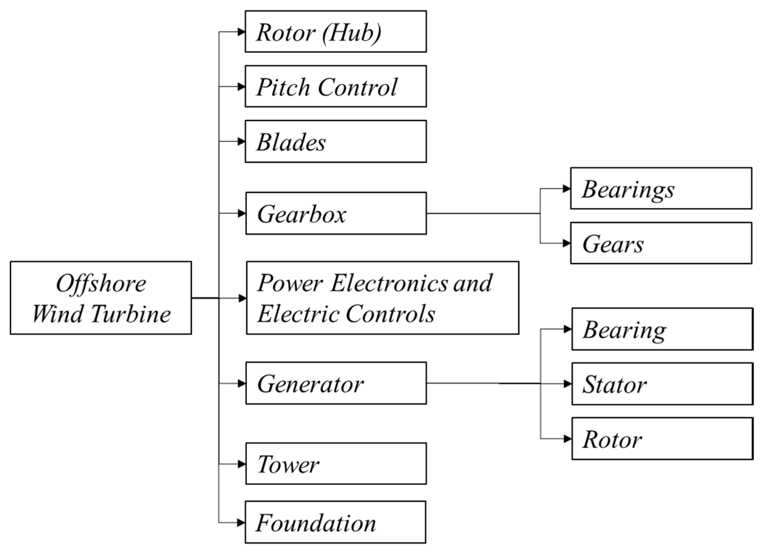
2. Service life Failure Mode Identification

From the beginning of an OWT project, during the planning stage and through to its early operation, an exhaustive failure mode identification is performed and frequently updated with special emphasis on all technological and environmental risks related to the installation and operation at a unit and farm level. This process aims to ensure safe and efficient operation, and develop an optimized maintenance plan that will allow the involved stakeholders (owners, manufacturing companies, third parties, etc.) to maintain the units in fit-for-service condition, setting the framework for the collection of data that can later allow the selection of the most profitable overall end of life scenario.
Currently failure identification procedures (such as Failure Mode Effect Analysis (FMEA), Failure Mode, Effects and Criticality Analysis (FMECA) and Fault Tree Analysis (FTA)) and design of experiments are being used for quality control and for the detection of potential failure modes during the design stage [9]. Failure mode identification is usually carried out by, first of all, breaking down the system into its main components or subsystems and these ones into their important parts and so on; secondly, an identification of the failure modes of every subsystem and their components should take place bearing in mind the interaction that each one has with others. Moreover, the consequences of these failure modes have to be assessed. As it was introduced before, different techniques are available, being FMEA one of most popular [10]. FMEA presents a logical, systematic and structured approach for developing a framework for the isolation and detection of failures, system maintenance planning, and categorization of actions [11]. This identification will, in practice, be carried out by the experts that afterwards will assess the probability of occurrence each failure has and its consequences or their criticality [12]. Moreover, it has become an essential process from the conceptual stage through the development to the design and testing stages [13]. However, in [14] FTA is considered to be better suited for “top-down” analysis. When used as a “bottom-up” tool FMEA can augment or complement FTA and identify many more causes and failure modes. In Figure 1, the breakdown of the system used for the OWT failure modes identification is presented. Moreover, a summary of the failure modes each one of the subsystems included in Figure 1 has, can be found in Table 1. In [15] the authors also employed a more advanced multi-criterion approach to risk prioritization employing the analytical hierarchy process for the determination of the most appropriate mitigation plan of operational risks of offshore wind infrastructures.
Figure 1. Offshore Wind Turbine broken down into subsystems and main components.
Energies 08 08339 g001
In this section, the main technological failure modes that might occur during the service life of OWTs have been identified and classified in order to identify phenomena that could jeopardize the life extension objective. Identifying the ways that a WT can fail is the first stage of the risk management process which will constitute the base of work on future life extension processes, making it a feasible practice.
Table 1. Failure modes summary.
Rotor (Hub)RefBladesRefGenerator (Bearing Stator and Rotor)Ref
Aerodynamic asymmetry[16]Cracks[17]Inter turn short circuit[18]
Yaw misalignment[19]Delaminations of the composite[20]Abnormal connection of the stator winding[18]
Creep and corrosion fatigue[21]Surface wear[22]Dynamic eccentricity[18]
Non-uniform air gap (bearings)[23]Increased surface roughness[24]Opening or shorting of stator or rotor winding circuits[18]
Hub spinng on shaft[21]Fatigue[25]Rotor eccentricity[26,27]
Shaft misalignment[17]Lightning strikes[28]Rotor broken bar[18]
Torsional oscillation[29]High vibrations[30]Rotor cracked end-ring[18]
Deviation in the torque-speed ratio[29]Flapwise fatigue damage[25]Torque reduction[31]
Mass imbalance[32]Unsteady blades air loads[33]Excessive stresses during operation[34]
Pitch controlRefBlade fracture [21]Static and/or dynamic air gap eccentricities[18]
Premature brake activation[21]Unsteady performance[28]Increased torque pulsation[18,31]
Inability of excessive operational load mitigation[35]Corrosion[28]Excessive heating in the winding[18]
Operation instability due to hydraulic system failure [36]Gearbox (bearings and gears)RefIncrease in losses and efficiency reduction[31]
Air contamination in the hydraulic system[37]Gear tooth damage[38]Rotor misalignment[39]
Inability of aerodynamic braking[35]Pitting[38]Imbalances and harmonics in the air gap flux[18,40]
Hydraulic fluid bulk modulus reduction[37]Cracking[38]Shorted winding coil (reduction in generator reactance)[29]
Leakage in the hydraulic system[37]Gear eccentricity[29]Tower and FoundationRef
Asymmetry in pitch angle[17]Tooth crack[29]Fatigue[41]
Power electronics and electric controlsRefShaft-Gearbox coupling failure[21]Cracks[42]
Semiconductor devices defects[43]Scratching (abrasive wear)[38]Corrosion[42]
Open circuit failure in 3-phase power converter[43]Scoring (adhesive wear)[38]Excessive fouling of foundation[44]
Short circuit failure in 3-phase power converter[43]Lubricant viscosity changes[26]Loss of capacity in foundation due to cyclic loading[45]
Gate-drive circuit failure in 3-phase power converter[43]Lubricant loss of water content[26]Soil instability[44]
Overheating[43]Presence of additives/debris in the lubricant[46]Earthquakes[44]
Error in wind speed/direction measurement[43]Change of modal parameters due to cyclic loading [45]
Scour[47]

2.1. Rotor and blades

Almost 20 years ago, a comprehensive analysis of rotor anomalies was performed, where the most common were stated to be aerodynamic asymmetry and yaw misalignment [16,19]. Even before that, an investigation into bearings’ behaviour due to non-uniform airgap and slip-speed was conducted in [23]. An investigation into drive train fault diagnosis of a synchronous WT generator focused on the torsional oscillation and the deviation of the torque/speed ratio [29]. Their study discusses the possibility of other rotor fault detection, potential that is also studied in [48] where, for example, the mass imbalance was identified and its consequences taken into account.
Blade integrity is a fundamental parameter of the operational performance of OWTs. Major rotor failure models are creep and corrosion fatigue [21], which could have catastrophic consequences due to incorrect maintenance and inspection of cracks, and delamination of the composite blades as a result of fatigue [17,20]. Rotor imbalance [32] and aerodynamic asymmetry might happen due to ice, dirt and moisture accumulation. Damage accumulation to the rotor blades can also be the root cause of these faults. Other common rotor failures are hubs spinning on the shaft [24] or shaft misalignments [17], among others. WTs can experience a decrease of the energy captured (efficiency loss) when the blade surface roughness increases [24]. This phenomenon and the surface wear [22] are produced by erosion, icing, etc., to which the WT is subjected. Another potential failure is the blades’ flapwise fatigue damage [25], which can be controlled or reduced by the pitch control system.
Unfortunately, WT blades undergo different fault and damage types that cannot all be captured by monitoring. Blades are subject to lightning strikes which are in principle random, natural phenomena. To prevent damage, lightning protection systems are employed [28]; however, complete protection is not guaranteed. Other common blade faults or direct consequences of these faults are: high vibrations [30], unsteady performance [28], corrosion and unsteady blades’ airloads [33], which in the worst scenario can produce blade fracture [21].

2.2. Pitch Control System

A pitch control system is a crucial element for the WT operation, due to the fact that it is responsible for efficient energy capture, operational load mitigation, WT stalling and aerodynamic braking [35]. Therefore, avoiding pitching failure is extremely important as this failure can lead to catastrophic consequences. Aerodynamic braking is used to stop the turbine when strong winds threaten its safe operation. This subsystem is usually managed by a hydraulic actuator or an electric motor. Although electric motors have a quicker response, they have lower stiffness and reliability than hydraulic systems and therefore are considered less fail-safe [17].
Certain faults of hydraulic systems produce operational instability [36], however, premature brake activation [21] also compromises their intended operational mode. Other examples of pitch control system failures are: the reduction of the hydraulic fluid effective bulk modulus produced by air contamination of the hydraulic system, reduction of plant bandwidth and significant leakage in the hydraulic system [37]. Those failures produce stability robustness reduction of the corresponding closed-loop system. Asymmetry in pitch angle [17] produces the WT shutdown during operation.

2.3. Gearbox

The gearbox has been found to be the component that suffers most faults among all the subsystems of the WT drive-train [17,49]. In a relevant study [38], gear tooth damage and bearing failure are determined as the more usual failures. The same study points out that “among all bearings in a planetary gearbox, the planet bearings, the intermediate shaft-locating bearings and high-speed locating bearings tend to fail at a higher rate, while the planet carrier bearings, hollow shaft bearings and non-locating bearings are most unlikely to fail”. Another important failure is the shaft-gearbox decoupling, which is considered to be catastrophic [21], while pitting, cracking, scratching and other faults are ranked with lower criticality [38], as they can be detected early enough through gearbox diagnosis and Condition Monitoring (CM) methods such as Acoustic Emission (AE) [50] or Auto-associative Kernel Regression (AAKR) [51]. Reference [29] presented a study related to WT drive-train diagnosis, where the electrical analysis was assessed for mechanical defects and the diagnosis of gear eccentricity was investigated.
Effective lubrication constitutes a very important aspect of the WT’s rotating components and particularly of the gearbox subsystem [52]. Variation in oil properties such as viscosity, water content, particle count, and presence of debris, commonly imply potential faults [26,46] and are often used as inspection methods.

2.4. Generator

The WT generators are among the subsystems with higher failure rates. Those failures mostly present on the stator, rotor and bearings. For induction machines, which are the most common, about 40% of failures occur to bearings, 38% to the stator and 10% to the rotor; as [18] concludes. Some of the major failures of these machines are: opening or shorting inter-turn failures at the stator’s or rotor’s winding circuits, stator winding abnormal connection, dynamic eccentricity, broken rotor bars, cracked end-rings, static and dynamic air-gap eccentricities, etc. Those failures’ consequences can also be considered potential faults; some of them are imbalances and harmonics in the air-gap flux and phase currents, increase on torque’s pulsation, decrease on the average torque, higher losses, loss of efficiency and winding’s overheating. In [39], a power signal was utilized to detect rotor misalignment and bearing faults using two techniques; Fast Fourier Transform (FFT) and Wavelet analysis.
One of the most important electrical faults that affect these machines is the shorted winding coil, which reduces the generator’s synchronous reactance. It is categorized as critical and immediate remedial action must be carried out right after its detection. In [29] it was demonstrated that a higher mechanical torque is needed to obtain equal shaft rotational speed when shorted coil is produced. Besides, shorted winding coil failure usually develops much faster, in the order of minutes, instead of the days or months that a mechanical degradation failure takes to occur.
Rotor fault types can be divided into rotor eccentricity, breakage of rotor cage bars and breakage of end-rings. Those failures are responsible for producing some secondary faults that cause serious malfunctions, as for example: winding and excitation imbalance or inter-turn short circuit. Rotor eccentricity exists when a non-symmetric air-gap is produced between the stator and the rotor when the latter is moved out of its position in the centre of the stator bore [40]. The maximum permissible level of eccentricity is between 5% and 10% of the air-gap length [27]. However, it must be rapidly detected, as the motor is damaged progressively due to the fact that, when the stator rubs the rotor or vice versa, catastrophic consequences to the winding, stator core and rotor cage can occur [40,53].
As explained in [34], rotor bars can be partially or completely cracked during the operation of Squirrel-Cage Induction Machines (SCIM), due to stresses and/or improper rotor geometry design. Bar breakage constitutes the worst failure for the SCIM rotor because when it happens, neighbouring bars’ deterioration starts as a result of the higher redistributed stresses. The most probable consequences of this failure are unbalanced currents and torque pulsation, which imply the average torque reduction [31].

2.5. Power Electronics and electric controls

Electronic controls represent 13% of the overall WT failures—even WT commissioning costs are just 1% [17]. For that reason, enhancing its diagnostic techniques is crucial. Besides it is important to note that power electronics represent a much higher cost percentage for variable speed and direct drive WT than for a constant speed WT [21].
Some studies have determined that most Power Electronics System failures occur due to semiconductor failures in the power electronics circuits. Thus some questionnaires were conducted for researching these device failures [43] focusing the effort on the 3-phase Power Converters’ major faults, which are: open circuit, short circuit and gate-drive circuit faults.
Results from the questionnaires concluded that “because of the time criticality of these faults, the fault detection and diagnostic methods for these semiconductor devices should be implemented as protection functions instead of monitoring functions”.

2.6. Tower and Foundation

The WT tower and foundation are both critical components due to the fact that they simply cannot be replaced in the same way as most other components. Therefore, as potential failure modes are fatigue [41], cracks and corrosion, the root causes of these must be regularly controlled by inspection and monitoring in order to ensure the integrity of the WT tower and foundations [42]. Even though a WT is designed for an operational life of 25 years, certain phenomena can impose worse threats than those anticipated during the design phase of the WT. Such phenomena could be earthquakes, unexpected soil instability or excessive fouling of the foundation, among others [44].
Unfortunately, some differences are usually found between the loading and environmental conditions that WTs are designed for, and the real conditions. These deviations can considerably increase the level of threat of some failure mechanisms such as corrosion and fatigue. Therefore, regular inspection and monitoring through Structural Health Monitoring Systems (SHMS) are strongly recommended for both the tower and foundation, especially at an early stage of the project so any variations can be addressed as soon as possible.
Foundations constitute a key element for the OWT, as their failure will lead to the structure’s collapse. Therefore a rigorous geotechnical assessment of the emplacement which may involve boreholes, vane tests, geophysical surveys, element testing using samples obtained from the site, among other techniques, has to take place early in the design process [54].
As explained in [45], cyclic capacities in the foundation design must be enough to sustain the structure to be subjected to external cyclic loads and maintain the level of deformation within acceptable limits. At the same time, foundations must withstand sufficient uncertainty levels, not only in soil conditions, but also in soil parameters, accuracy in calculation methods and loading estimation. However, as happened with the tower design, differences between design and real conditions have also to be minimized and controlled in the foundation design, due to the criticality of this subsystem [55].
Thus, it is natural to believe that WT foundations are provided with the same kind of warranty WTs have; however, they are usually not. Instead, foundation risks are insurable and can be mitigated through certification [47].
Therefore, WT foundation’s maintenance has to be carried out in a different way; mostly by visual inspections and survey work, while performing those risks remediation labours only if it is completely necessary. These different types of inspections assess the structural strength, lifting, climbing and safety equipment, corrosion and scour protection. Foundation and sub-sea structure maintenance includes painting reparations, excess of marine growth removal and rock placing to enhance the foundations’ risk mitigation against scour, and occasional reparations to wave-damaged tower facilities such as stairs, gates, grills and platforms.

3. Review of EOL scenarios

Within this section, a review of the three most applicable EOL scenarios is presented. These are: life extension, which consists of extending the service life of the unit, with the economic profit that implies; repowering, which represents the procedure of rebuilding a WT in the same location as the existing one, either replacing just some parts or building a completely new unit; and decommissioning if either of the two other options are not feasible.

3.1. Life Extension

Under certain circumstances, when a WT approaches its final years of service life it might be worth refitting it to increase its service life, rather than terminate its operation and decommission it. An extensive inspection will usually determine the requirement for replacement of the most critical internal subsystems (i.e., generator) and the blades [56], while an intensive assessment has to be performed in order to determine the suitability and safety of the sustained subsystems. It is common for the tower to be still fit-for-purpose and be used safely for further additional years. Common spares costs are usually between the 5% (rotor hub) and the 20% (blades) of a new WT cost [57].
Detailed research and posterior analysis of the United Kingdom Wind Farms (WFs) was performed in 2014, and determined that most WTs will last for about 25 years before they need to be upgraded [58]. It was also concluded that the first set of the UK’s WTs, deployed in the 90s, after their whole normal service life, were still being profitable due to the fact that their power production was about 75% of their nominal production; hence it was estimated that they might still have five years of further operation.
An analysis of different life extension scenarios was also performed in [59] to estimate the feasibility of the operational life extension and its environmental impact through Life Cycle Assessment (LCA). This analysis was carried out for life extension periods of five and ten years, following a normal service life of 25 years. For the LCA study, energy production, and additional maintenance, including materials and services, were taken into consideration.
As pointed out before, the better the quality and management of the inspection and O&M activities of WTs, the higher chance they have of being suitable for life extension. According to [60], the cost of offshore O&M activities currently varies from two to five times the cost onshore. One of the reasons might be the additional effort that is being put in building WTs that will resist the environmental harshness of the offshore environment and avoid these specific environmental risks, which makes not only CAPEX, but also O&M costs even more expensive [61,62]. This is the reason why operators are currently looking for strategies that enhance the efficient operation of these turbines, which will clearly diminish the O&M costs.
One of the best ways of enhancing efficient operation and therefore, life extension, is by using Structural Health Monitoring and Condition Monitoring (SHM/CM) Systems, as part of a Condition Based Maintenance (CBM) paradigm with smart loads management [63]. CBM strategies allow the planning of maintenance activities and inspections based on the data of SHM/CM Systems [64].
By constantly monitoring the health of WTs’ structural components, required maintenance activities can be planned in advance and carried out when necessary at the offshore emplacement rather than after failure has already happened [65,66]. Currently, these systems are being adapted to Offshore Wind. SHM/CM systems are already widely used in some subsystems, such as generators and gearboxes; however, others are still waiting for the development of a framework that assesses all the collected data and indicates the health of the subsystem.
Operating WTs based on the health of the structure will allow their deareation when a certain level of damage is detected at an early stage by the SHM System. This will reduce the power production but at the same time it will increase the service life of the WTs, decrease maintenance costs and increase WF’s efficiency. Some simulations carried out by [60] showed that when a turbine is deareated, diminishing the power production by 5%, a fatigue life extension in the blades reached 300% due to a decrease of 10% in the equivalent loading.
Moreover, in order to achieve the life extension of a WF, a thorough failure modes and risk identification and an assessment of the factors that influence O&M costs should be performed to determine if life extension is possible.

3.2. Repowering

Repowering accounts for the process of either rebuilding existing WTs with new ones that have larger rated power and efficiency, or replacing the turbine while reusing the tower. Therefore, in the last years of a WF’s operational life, the owner might decide whether repowering is a profitable option and under which conditions it might be carried out. This decision should be based on the following [67]:
  • The WF’s profitability—as time passes both performance and reliability decrease.
  • The profits expectation for both life extension and the different repowering options.
  • The cost-benefit ratio that repowering will present against the full decommissioning of the WF and project components recycling.
There are three different options of repowering that depend on the status of the actual WT and they can be summarized as follows:
  • Same tower with a new, lower capacity turbine: this option combines a smaller WT that may even produce less electricity, needs less maintenance (higher availability) and have a nominal service life of an additional 25 years, with the same tower that, having decreased the power of the turbine, will have less applied loads and therefore longer fatigue life.
  • Same tower with a new, higher capacity turbine: this option combines a higher WT that will produce more electricity and will last another 25 years, with the same tower that having increased the power of the turbine will be subject to greater loads and therefore its structural integrity should be rigorously reassessed. For that reason, this option usually will not be favourable, unless the structural integrity of the tower will be sufficient to fulfil the new requirements.
  • New tower with a new, higher capacity turbine: this option entails the tower and nacelle decommissioning for the later commissioning of a new WT.
All three options assume reusing part of the infrastructure from the Offshore Wind Farm (OWF) to reduce the capital cost of the new one (after repowering). For example, most of the original subsea cables might be reused, along with the existing grid connection. However, if the WT capacity has been increased, the grid connection may have to be upgraded.
In order to repower, a distinct financial process should be undertaken, leading to a second construction phase and O&M phase, with all that these phases entail [67]. Most of the time, WTs are erected in high wind resource locations where replacing a WT that has exceeded its nominal service life with another one with the same or better characteristics promises to be profitable. Some examples of repowered WFs can be found in California, Nevada, Holland and Denmark. In particular, a good example of repowering is taking place in the United Kingdom, where RWE npower Renewables obtained consent to perform the repowering of one of the first Onshore WFs. The project will consider reduction of the quantity of WTs, doubling the power generation, which means that the WF built in 1993 and made of 20 WTs will be transformed into a WF composed by seven WTs with a capacity of 17.5 MW, which accounts for more than twice the actual power generated each year [58].

3.3. Decommissioning

The decommissioning of a WF constitutes the final stage of a project when service life extension or repowering is not a financially feasible practice. It is also the least desirable EOL scenario. The main objective of this stage is returning the seabed to its original conditions prior to initial deployment [67]. In the decommissioning phase of a WF, all WT elements have to be transferred by vessels and trucks from offshore, onshore and finally, to their treatment location [68]. If a WT needs to be totally dismantled, firstly all blades, nacelle and the tower will be disassembled and hoisted down by crane; its posterior elements will be disjointed and reduced into smaller pieces suitable for scrap [69]. Almost every part of the WT material will be recycled. It should be noted that the qualification and crew for the decommissioning activities used, is comparable to those of the commissioning stage.
The recycling scenario proposed by [59] explains the way that the OWF is distributed over the decommissioning EOL options. Firstly, the OWF is disassembled and separated into elements by assuming identical energy consumption to that of the commissioning phase. Then, waste treatment is performed, depending on the kind of material used. Waste treatments are divided into recycling, landfilling, and incineration. Decommissioning and recycling implications and costs must be clear to all stakeholders (municipalities, small land owners and WT developers).

4. Conclusions

Currently WTs are designed for an assumed service life of 25 years with the possibility of operational extension. It becomes obvious that extending the efficient operation and hence increasing the overall amount of produced electricity may significantly increase the return on investment (ROI) and decrease the LCOE, considering that CAPEX will be distributed over a larger production output. However, even though this might be the potentially preferred EOL scenario, it is not always feasible due to the increase in OPEX that can be introduced from operating beyond the nominal service life period of WT units. In order to assess the suitability of service life extension, an exhaustive failure mode identification must take place for all project phases and a comparison of those to the applied risk management strategy with an appropriate O&M plan and associated costs must be performed. If finally life extension is not possible, other options such as repowering or decommissioning must be explored.
This paper has presented a review of the different failure modes WTs might present along their service life and moreover, a review of the three EOL scenarios applicable to WTs approaching the end of their lifespan. It is believed that in order to extend the service life of a WT, a failure modes and risk identification and an assessment of the factors that influence O&M costs should be carried out and the unit’s health should be assessed by the use of SHM/CM systems. However, further efforts should be put into creating a methodology for extrapolating WTs’ assessment results to the whole WF, as just one EOL scenario will be chosen for it. Furthermore, each EOL scenario’s profitability must be carefully assessed for each particular case.

Acknowledgments

This work was supported by the Natural Environment Research Council (NERC).

Author Contributions

Maria Martinez Luengo was in charge of writing the paper, whilst Athanasios Kolios supervised the work and made the revisions.

Conflicts of Interest

The authors declare no conflict of interest.

References

  1. Lozano-Minguez, E.; Kolios, A.J.; Brennan, F.P. Multi-criteria assessment of offshore wind turbine support structures. Renew. Energy 2011, 36, 2831–2837. [Google Scholar] [CrossRef] [Green Version]
  2. European Commission. Communication from the Commission to the European Parliament, the Council, the European Economic and Social Committee and the Committee of the Regions. Available online: http://ec.europa.eu/europe2020/pdf/europe2020stocktaking_en.pdf (accessed on 3 August 2015).
  3. European Union Committee. The EU’s Target for Renewable Energy: 20% by 2020, 2008. Available online: http://www.publications.parliament.uk/pa/ld200708/ldselect/ldeucom/175/175.pdf (accessed on 3 August 2015).
  4. Nikolau, N. Deep Water Offshore Wind Technologies. Master’s Thesis, University of Strathclyde, Glasgow, Scotland, September 2004. [Google Scholar]
  5. Kolios, A.J.; Rodriguez-Tsouroukdissian, A.; Salonitis, K. Multi-criteria decision analysis of offshore wind turbines support structures under stochastic inputs. Ships Offshore Struct. 2014, 2014. [Google Scholar] [CrossRef]
  6. Martin, H.; Spano, G.; Küster, J.F.; Collu, M.; Kolios, A.J. Application and extension of the TOPSIS method for the assessment of floating offshore wind turbine support structures. Ships Offshore Struct. 2013, 8, 477–487. [Google Scholar] [CrossRef]
  7. Kolios, A.J.; Read, G. A political, economic, social, technology, legal and environmental (PESTLE) approach for risk identification of the tidal industry in the United Kingdom. Energies 2013, 6, 5023–5045. [Google Scholar] [CrossRef] [Green Version]
  8. Kolios, A.J.; Read, G.; Ioannou, A. Application of multi-criteria decision-making to risk prioritisation in tidal energy developments. Int. J. Sustain. Energy 2014, 2014. [Google Scholar] [CrossRef]
  9. Arunajadai, S.G.; Uder, S.J.; Stone, R.B.; Tumer, I.Y. Failure mode identification through clustering analysis. Qual. Reliab. Eng. Int. 2004, 20, 511–526. [Google Scholar] [CrossRef]
  10. Stamatis, D.H. Failure Mode and Effect Analysis: FMEA from Theory to Execution, 2nd ed.; ASQ Quality Press: Milwaukee, WI, USA, 2003. [Google Scholar]
  11. Liu, H.-C.; Liu, L.; Liu, N. Risk evaluation approaches in failure mode and effects analysis: A literature review. Expert Syst. Appl. 2013, 40, 828–838. [Google Scholar] [CrossRef]
  12. Military Standard, Procedures for Performing a Failure Mode, Effects and Criticality Analysis; MIL-STD-1629A; Department of Defense: Arlington County, VA, USA, November 1980.
  13. Bowles, J. Fundamentals of failure mode and effect analysis. In Proceedings of the 2012 Annual Reliability and Maintainability Symposium, Nugget Hotel and Resort Reno, NV, USA, 23–26 January 2012.
  14. Kmenta, S.; Ishii, K. Scenario-Based Failure Modes and Effects Analysis Using Expected Cost. J. Mech. Des. 2004, 126, 1027–1035. [Google Scholar] [CrossRef]
  15. Shafiee, M.; Kolios, A. A multi-criteria decision model to mitigate the operational risks of offshore wind infrastructures. In Safety and Reliability: Methodology and Applications; CRC Press: Boca Raton, FL, USA, 2014; pp. 539–547. [Google Scholar]
  16. Caselitz, P.; Giebhardt, J.; Mevenkamp, M. Application of condition monitoring systems in wind energy convertors. In Proceedings of the European Wind Energy Conference, EWEC’97, Dublin, Ireland, 6–9 October 1997; pp. 579–582.
  17. Lu, B.; Li, Y.; Wu, X.; Yang, Z. A review of recent advances in wind turbine condition monitoring and fault diagnosis. In Proceedings of 2009 Power Electronics and Machines in Wind Applications (PEMWA 2009), Lincoln, NE, USA, 24–26 June 2009; pp. 1–7.
  18. Popa, L.M.; Jensen, B.-B.; Ritchie, E.; Boldea, I. Condition monitoring of wind generators. In Proceedings of the 38th IAS Annual Meeting on Industry Applications Conference, Salt Lake City, UT, USA, 12–16 October 2003; pp. 1839–1846.
  19. Caselitz, P.; Giebhardt, J.; Mevenkamp, M. Online fault detection and prediction in wind energy convertors. In Proceedings of the European Wind Energy Conference, EWEC’94, Thessaloniki, Greece, 10–14 October 1994; pp. 623–627.
  20. Tsai, C.S.; Hsieh, C.-T.; Huang, S.J. Enhancement of damage detection of wind turbine blades via CWT-based approaches. IEEE Trans. Energy Convers. 2006, 21, 776–781. [Google Scholar] [CrossRef]
  21. Kusiak, A.; Zhang, Z.; Verma, A. Prediction, operations, and condition monitoring in wind energy. Energy 2013, 60, 1–12. [Google Scholar] [CrossRef]
  22. Rumsey, M.A.; Paquette, J.A. Structural health monitoring of wind turbine blades. Proc. SPIE 2008, 6933. [Google Scholar] [CrossRef]
  23. Brusa, E.; Amati, N. Condition monitoring of rotors on active magnetic bearings (AMB) fed by induction motors. In Proceedings of IEEE/ASME Advanced Engineering Mechatronics, Como, Italy, 8–12 July 2001; pp. 750–756.
  24. Boger, L.; Wichmann, M.H.G.; Meyer, L.O.; Schulte, K. Load and health monitoring in glass fibre reinforced composites with an electrically conductive nanocomposite epoxy matrix. Compos. Sci. Technol. 2008, 68, 1886–1894. [Google Scholar] [CrossRef]
  25. Arrigan, J.; Pakrashi, V.; Basu, B.; Nagarajaiah, S. Control of flapwise vibrations in wind turbine blades using semi-active tuned mass dampers. Struct. Control. Health Monit. 2010, 18, 840–851. [Google Scholar] [CrossRef]
  26. Orsagh, R.F.; Lee, H.; Watson, M.; Byington, C.S.; Powers, J. Advanced Vibration Monitoring for Wind Turbine Health Management. Available online: http://rlwinc.com/Resources/TechnicalPublicationPDFs/PowerandIndustrial/Impact_PI_IMSASD-AWEA%20HUMS.pdf (accessed on 3 August 2015).
  27. Thomson, W.T.; Gilmore, R.J. Motor current signature analysis to detect faults in induction motordrives: Fundamentals, data interpretation and industrial case histories. In Proceedings of the 32nd Turbomachinery Symposium, Houston, TX, USA, 9–11 September 2003; pp. 45–156.
  28. Cotton, I.; Jenkins, N.; Pandiaraj, K. Lightning protection for wind turbine blades and bearings. Wind Energy 2001, 4, 23–37. [Google Scholar] [CrossRef]
  29. Yang, W.; Tavner, P.J.; Wilkinson, M.R. Condition monitoring and fault diagnosis of a wind turbine synchronous generator drive train. IET Renew. Power Gener. 2009, 3, 1–11. [Google Scholar] [CrossRef]
  30. Volanthen, M. Blade and rotor condition monitoring using blade load measurement data. In Proceedings of Non-Grid-Connected Wind Power Systems; American Scholars Press: Marietta, GA, USA, 2007; pp. 468–473. [Google Scholar]
  31. Ilonen, J.; Kamarainen, J.-K.; Lindh, T.; Ahola, J.; Kälviäinen, H.; Partanen, J. Diagnosis tool for motor condition monitoring. IEEE Trans. Ind. Appl. 2005, 41, 963–971. [Google Scholar] [CrossRef]
  32. Niebsch, J.; Ramlau, R.; Nguyen, T.T. Mass and aerodynamic imbalance estimates of wind turbines. Energies 2010, 3, 696–710. [Google Scholar] [CrossRef]
  33. Shen, X.; Zhu, X.; Du, Z. Wind turbine aerodynamics and loads control in wind shear flow. Energy 2011, 36, 1424–1434. [Google Scholar] [CrossRef]
  34. Mehrjou, M.R.; Mariun, N.; Marhaban, M.H.; Misron, N. Rotor fault condition monitoring techniques for squirrel-cage induction machine. Mech. Syst. Signal Process. 2011, 25, 2827–2848. [Google Scholar] [CrossRef]
  35. Hansen, M.H. How Hard can it be to Pitch a Wind Turbine Blade? RISO Lab, Denmark Technical University. Available online: www.risoe.dtu.dk/rispubl/art/2007_321_presentation.pdf (accessed on 3 August 2015).
  36. Yang, X.; Li, J.; Liu, W.; Guo, P. Petri net model and reliability evaluation for wind turbine hydraulic variable pitch systems. Energies 2011, 4, 978–997. [Google Scholar] [CrossRef]
  37. Watton, J. Modelling, Monitoring and Diagnostic Techniques for Fluid Power Systems; Springer Science & Business Media: Berlin/Heidelberg, Germany, 2007. [Google Scholar]
  38. McNiff, B. The gearbox reliability. In Proceedings of the 2nd Sandia National Laboratories Wind Turbine Reliability Workshop, Albuquerque, NM, USA, 17–18 September 2007.
  39. Watson, S.J.; Xiang, J. Real-time condition monitoring of offshore wind turbines. In Proceedings of European Wind Energy Conference & Exhibition (EWEC), Athens, Greece, 27 February–2 March 2006; pp. 647–654.
  40. Cameron, J.R.; Thomson, W.T.; Dow, A.B. Vibration and current monitoring for detecting airgap eccentricity in large induction motors. IEE Proc. B Electr. Power Appl. 1986, 133, 155–163. [Google Scholar] [CrossRef]
  41. Márquez-Domínguez, S.; Sørensen, J.D. Fatigue reliability and calibration of fatigue design factors for offshore wind turbines. Energies 2012, 5, 1816–1834. [Google Scholar] [CrossRef]
  42. Sørensen, J.D. Reliability assessment of wind turbines. In Proceedings of the European Safety and Reliability Conference, ESREL 2013, Amsterdam, The Netherlands, 29 September–2 October 2013.
  43. Lu, B.; Sharma, S. A literature review of IGBT fault diagnostic and protection methods for power inverters. IEEE Trans. Ind. Appl. 2009, 45, 1770–1777. [Google Scholar]
  44. Van der Woude, C.; Narasimhan, S. A study on vibration isolation for wind turbine structures. Eng. Struct. 2014, 60, 223–234. [Google Scholar] [CrossRef]
  45. Andersen, K.H.; Puech, A.A.; Jardine, R.J. Design for cycling loading: Piles and other foundations. In Proceedings of 18th International Conference on Soil Mechanics and Geotechnical Engineering (ICSMGE), Paris, France, 2–6 September 2013.
  46. Tandon, N.; Parey, A. Condition Monitoring of Rotary Machines, Condition Monitoring and Control for Intelligent Manufacturing; Springer: London, UK, 2006; pp. 109–136. [Google Scholar]
  47. GL Garrad Hassan. A Guide to UK Offshore Wind Operations and Maintenance. 2013. Available online: http://www.4-power.eu/media/3109/offshore-wind-guide-june-2013.pdf (accessed on 3 August 2015).
  48. Andrawus, J.A.; Watson, J.; Kishk, M.; Adam, A. The selection of a suitable maintenance strategy for wind turbines. Wind Eng. 2006, 30, 471–486. [Google Scholar] [CrossRef]
  49. Wilkinson, M.R.; Spinato, F.; Tavner, P.J. Condition monitoring of generators and other subassemblies in wind turbine drive trains. In Proceedings of International Symposium on Diagnostics for Electric Machines, Power Electronics and Drives (SDEMPED 2007), Cracow, Poland, 6–8 September 2007; pp. 388–392.
  50. Tchakoua, P.; Wamkeue, R.; Ouhrouche, M.; Slaoui-Hasnaoui, F.; Tameghe, T.A.; Ekemb, G. Wind turbine condition monitoring: State-of-the-art review, new trends, and future challenges. Energies 2014, 7, 2595–2630. [Google Scholar]
  51. Guo, P.; Bai, N. Wind turbine gearbox condition monitoring with AAKR and moving window statistic methods. Energies 2011, 4, 2077–2093. [Google Scholar] [CrossRef]
  52. Mobley, R.K. An Introduction to Predictive Maintenance, 2nd ed.; Heinemann: Butterworth, NH, USA, 2006. [Google Scholar]
  53. Faiz, J.; Ojaghi, M. Different indexes for eccentricity faults diagnosis in three-phase squirrel-cage induction motors: A review. Mechatronics 2009, 19, 2–13. [Google Scholar] [CrossRef]
  54. Fleming, K.; Weltman, A.; Randolph, M.; Elson, K. Piling Engineering; CRC Press: Boca Raton, FL, USA, 2009. [Google Scholar]
  55. Brennan, F.; Kolios, A. Structural integrity considerations for the H2Ocean multi modal wind-wave platform. In Proceedings of European Wind Energy Association (EWEA) Conference and Exhibition 2014, Barcelona, Spain, 10–13 March 2014.
  56. Operational and Maintenance Costs for Wind Turbines. Available online: http://www.windmeasurementinternational.com/wind-turbines/om-turbines.php (accessed on 12 March 2015).
  57. Renewable Energy Technologies: Cost Analysis Series; Volume 1: Power Sector Issue 5/5 Wind Power. 2012. Available online: https://www.irena.org/DocumentDownloads/Publications/RE_Technologies_Cost_Analysis-WIND_POWER.pdf (accessed on 3 August 2015).
  58. Staffell, I.; Green, R. How does wind farm performance decline with age? Renew. Energy 2014, 66, 775–786. [Google Scholar] [CrossRef]
  59. Muro Pereg, J.R.; Fernandez de la Hoz, J. Life Cycle Assessment of 1 kWh generated by a GAMESA Onshore Windfarm G90 2.0 Mw, Gamesa 2013. Available online: http://www.gamesacorp.com/recursos/doc/rsc/compromisos/clientes/certificaciones-ohsas-y-i/informe-analisis-ciclo-de-vida-g90-english.pdf (accessed on 1 April 2015).
  60. Griffith, D.T.; Yoder, N.C.; Resor, B.; White, J.; Paquette, J. Structural health and prognostics management for the enhancement of OWT operations and maintenance strategies. Wind Energy 2014, 17, 1737–1751. [Google Scholar] [CrossRef]
  61. Levitt, A.C.; Kempton, W.; Smith, A.P.; Musial, W.; Firestone, J. Pricing offshore wind power. Energy Policy 2011, 39, 6408–6421. [Google Scholar] [CrossRef]
  62. Musial, W.; Ram, B. Large-Scale Offshore Wind Energy for the United State: Assessment of Opportunities and Barriers; No. NREL/TP-500-40745; National Renewable Energy Laboratory (NREL): Golden, CO, USA, 2010. [Google Scholar]
  63. Griffith, D.T.; Yoder, N.C.; Resor, B.; White, J.; Paquette, J.; Ogilvie, A.; Peters, V. Prognostic control to enhance offshore wind turbine operation and maintenance strategies. In Proceedings of European Wind Energy Conference (EWEA) Annual Event, Copenhagen, Denmark, 16–19 April 2012.
  64. Besnard, F.; Fischer, K.; Bertling, L. Reliability-centered asset maintenance: A step towards enhanced reliability, availability, and profitability of wind power plants. In Proceedings of IEEE PES Innovative Smart Grid Technologies Conference Europe (ISGT Europe), Gothenburg, Sweden, 11–13 October 2010.
  65. Amirat, Y.; Benbouzid, M.E.H.; Bensaker, B.; Wamkeue, R. Condition monitoring and fault diagnosis in wind energy conversion systems: A review. In Proceedings of 2007 IEEE International Electric Machines and Drives Conference, Antalya, Turkey, 3–5 May 2007; pp. 1434–1439.
  66. Ciang, C.C.; Lee, J.R.; Bang, H.J. Structural health monitoring for a wind turbine system: A review of damage detection methods. Meas. Sci. Technol. 2008, 19, 1–20. [Google Scholar] [CrossRef]
  67. Offshore Wind, Onshore Jobs: A New Industry for Britain; Energy for Sustainable Development (ESD) Ltd for Greenpeace, UK. 2009. Available online: http://www.greenpeace.org.uk/MultimediaFiles/Live/FullReport/6702.pdf (accessed on 3 August 2015).
  68. Tsai, L. An Integrated Assessment of Offshore Wind Farm Siting: A Case Study in the Great Lakes of Michigan. PhD Thesis, University of Michigan, Ann Arbor, MI, USA, 2013. [Google Scholar]
  69. Aakre, D.; Hangen, R. Wind Turbine Considerations for Landowners, NDSU Extension Service, North Dakota State University. 2009. Available online: http://www.ag.ndsu.edu/pubs/agecon/market/ec1394.pdf (accessed on 12 March 2015).

