
Increasing the Energy Efficiency of Gas Boosters for Hydrogen Storage and for Refueling Stations

EPFL—Ecole Polytechnique Fédérale de Lausanne, STI-DO, Station 11, 1015 Lausanne, Switzerland
Energies 2023, 16(4), 1763; https://doi.org/10.3390/en16041763
Submission received: 18 December 2022
/
Revised: 19 January 2023
/
Accepted: 29 January 2023
/
Published: 10 February 2023
(This article belongs to the Special Issue Review Papers in Energy Storage and Related Applications)
Abstract
:A new electrically driven gas booster is described as an alternative to the classical air-driven gas boosters known for their poor energetic efficiency. These boosters are used in small scale Hydrogen storage facilities and in refueling stations for Hydrogen vehicles. In such applications the overall energy count is of significance and must include the efficiency of the compression stage. The proposed system uses an electric motor instead of the pneumatic actuator and increases the total efficiency of the compression process. Two mechanical principles are studied for the transformation of the rotational motion of the motor to the linear displacement of the compressor pistons. The strongly fluctuating power of the compressor is smoothed by an active capacitive auxiliary storage device connected to the DC circuit of the power converter. The proposed system has been verified by numeric simulation, including the thermodynamic phenomena, the kinetics of the new compressor drive and the the operation of the circuits of the power smoothing system.
1. Introduction
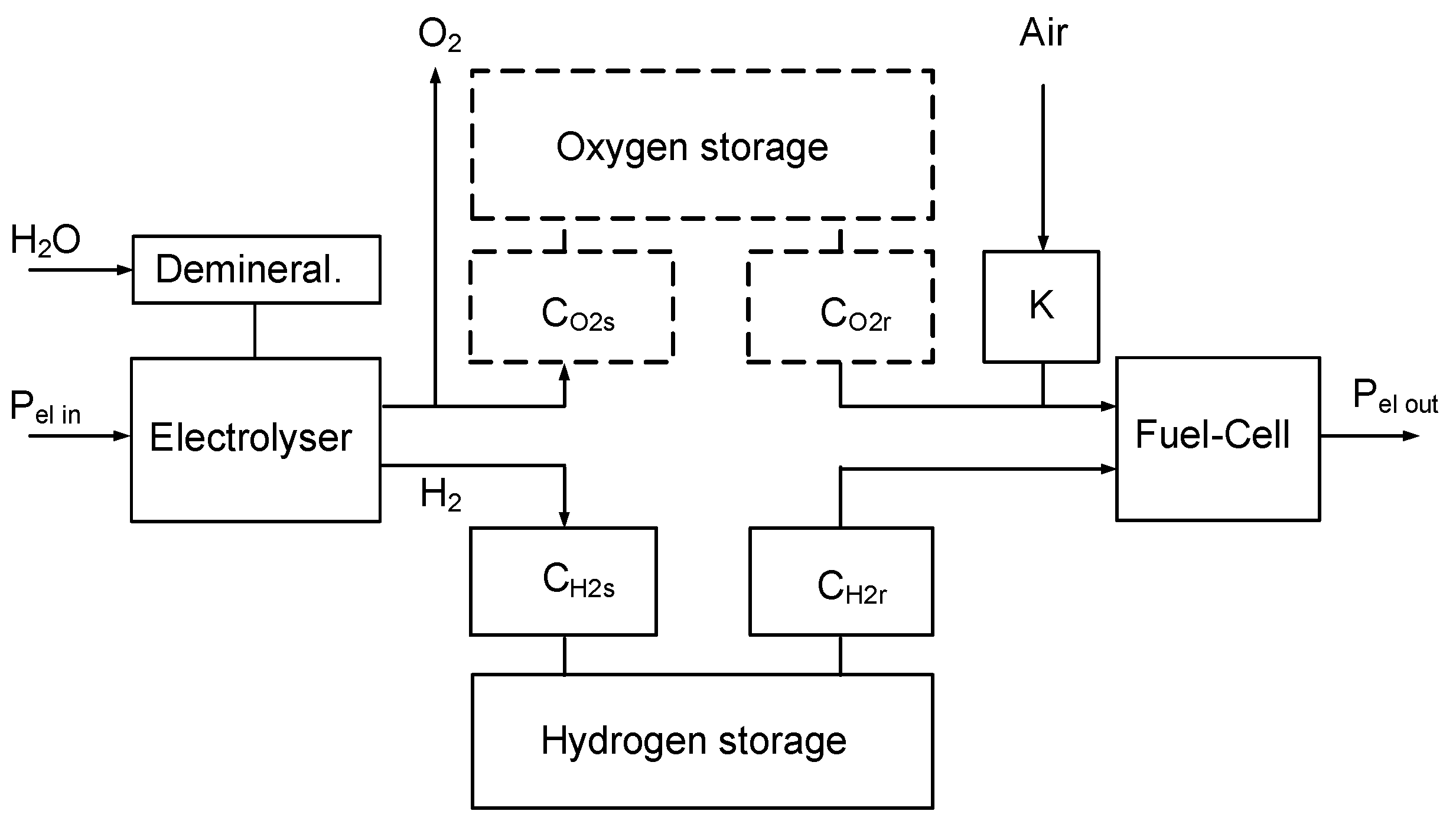
Green Hydrogen is a promising energy vector in the sector of automotive vehicles especially in the context of reducing the emissions of greenhouse gases. In the domain of domestic energy storage and especially if the seasonal context of photovoltaic power is considered, Hydrogen conversion and use can play an important role. Due to its low weight density, Hydrogen must be stored locally or on-board in high pressure reservoirs. A simplified representation of a storage station is given in Figure 1.
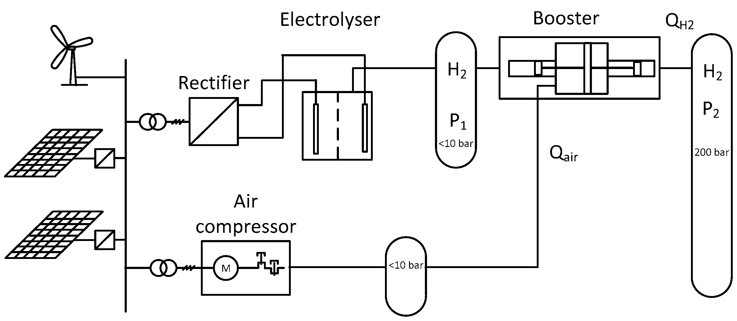
In such a system, the green fuel is generated from electric renewable sources feeding a water electrolyser. Then the gaseous fuel is stored in a reservoir and is further used in the fuel-cell based generator. In Figure 1, an oxygen storage element is also represented with a dotted line, evoking such a possibility. However, for most fuel-cell systems, the oxidation of Hydrogen in the cell stack is realized with oxygen taken from the ambient air. In Figure 2, a more detailed scheme of the Hydrogen generation and storage is represented. The supply of the electrolyser is provided by a local grid where the renewable energy sources are connected. This grid is supplying also the air compressor which provides the auxiliary fluid to activate the gas booster.
In this system, the green fuel is pressurized to a high-pressure level around 700 bar (700 × 105 Pa) for personal vehicles or 350 bar for heavy means of transportation. For domestic Hydrogen storage there are today no standard pressure levels, but for economic reasons, the domestic pressure standard could be similar to the levels as in transportation. Mass development in this sector in the future would offer strong reduction of the prices of storage reservoirs and other components [1]. For equipment in the domain of several kilowatts or tens of kilowatts of power, the pressurization machinery is realized conventionally by air driven gas boosters which are known for their simplicity, reliability and low costs [2].
In addition to the technique of storage of Hydrogen by compression, storage in liquid form is also possible. However, because of the very low liquefaction temperature of hydrogen (around 20 K under atmospheric pressure), the liquid storage of hydrogen is not economical. Another possibility is storage in the form of a solid material by adsorption, as a metal hydrid [3,4]. Further techniques such as the transformation into formic acid through catalytic hydrogenation are possible [5]. However, the alternative techniques to compression are characterized by lower energy densities of the stored Hydrogen and demand complex infrastructures.
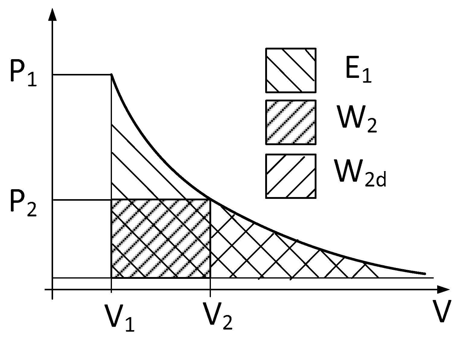
For the compression device represented in Figure 2, the poor energetic efficiency of a pneumatic motor in the gas booster addresses the question of the total efficiency of a complete storage station. In general, the main cause of the poor efficiency of pneumatic actuators resides in the fact that the air under pressure accumulated in the working chambers is simply released to the surroundings before initiating the return strokes. Figure 3 shows a pressure-to-volume diagram of the thermodynamic change of state of the air in a pneumatic cylinder, where constant pressure displacement work is represented with the finely hatched square surface W2 between V1 and V2. This surface corresponds to the effectively produced mechanical work by a cylinder under constant pressure P2. To the left of the V2 value of the volume, the surface under the decreasing curve (W2d) corresponds to the recoverable expansion work corresponding to the lost energy when the exhaust valve is opened.
A better use of the pressurized air of a cylinder has been proposed, using the principle of adding an expansion work component to the constant pressure displacement work, thus recovering the internal energetic content of the in-taken air [6,7,8,9]. In principle, the addition of an expansion chamber can increase the cylinder system efficiency from around 0.35 to 0.7 [8]. With the same goal to improve the efficiency, the principle of using the expansion energy has been applied to a pneumatic booster [10]. Another better adapted system is based on the use of an additional expansion cylinder mechanically coupled to the filling cylinder [11]. The resultant active force is in this case better adapted to the compression characteristics but needs a specific design to be able to provide a sufficient effort over the full length of the strokes, especially at the end of a compression stage when the increased pressure needs a high compression effort.
In this paper, an electrically driven gas booster is proposed, where the mechanical force is provided by a classical electric motor. The coupling of the rotational motion of the motor to the linear displacement of the compression stages can be realized on the basis of two different mechanisms. A classical crankshaft and two connecting rods can be used, or a special mechanism called the Scotch Yoke. These two possibilities will be described in the following sections. The original compression cylinders of the booster are conserved and placed on both sides of the new mechanisms. The strongly fluctuating compression forces of the pistons at a low frequency result in a strongly modulated power of the electric motor. For smoothing the power taken from the electrical feeding grid, an active power compensation system using a variable voltage capacitor is connected to the DC link of the frequency converter of the electric drive.
The proposed electrically driven gas booster is studied in the context of Hydrogen compression in storage facilities or in refueling stations, but such a system can be used for any other gases when its design and operation conditions are adapted.
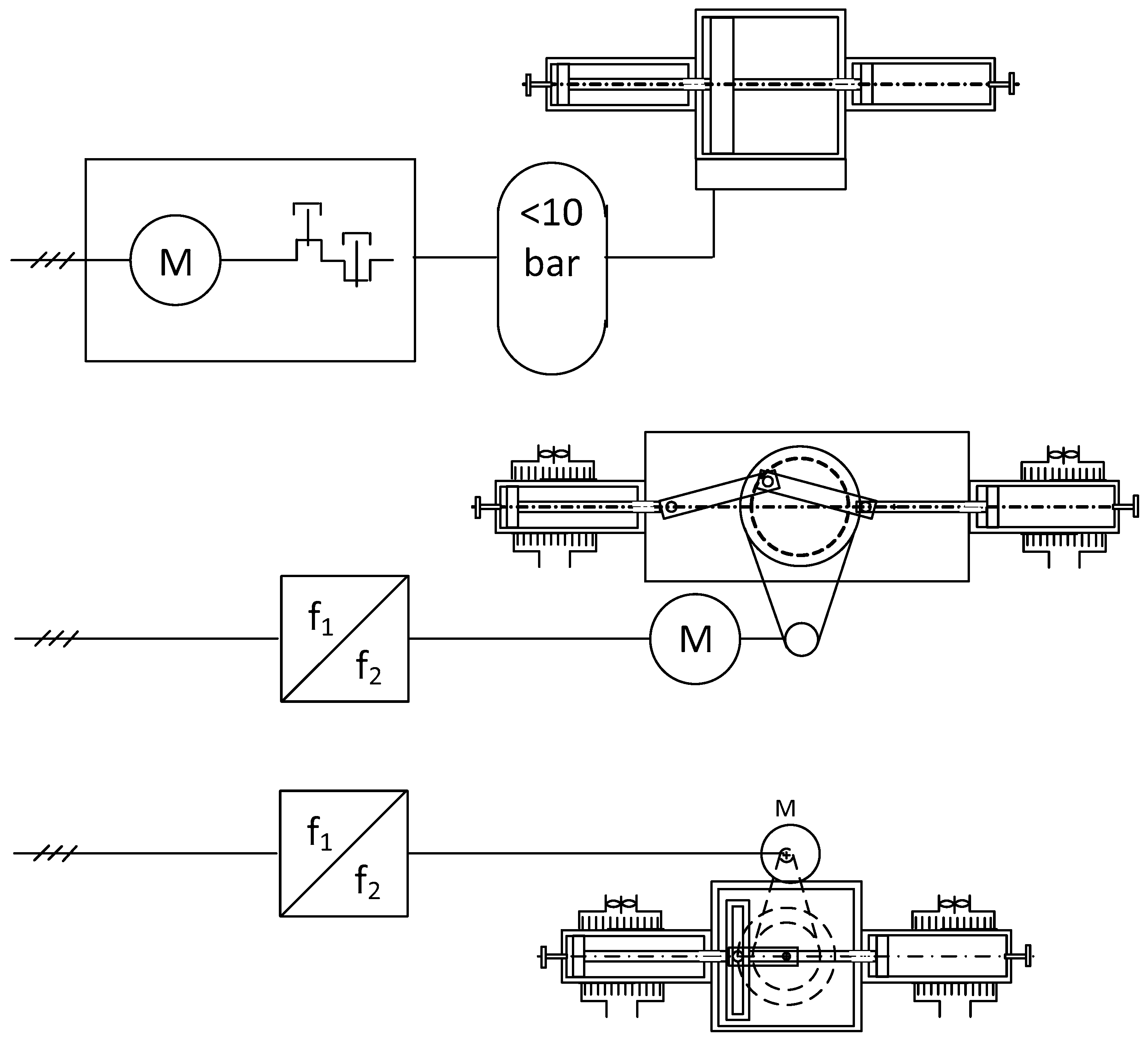
2. An Electric Motor Instead of the Common Pneumatic Actuator
Figure 4 shows at the top the classical air-driven gas booster with the complete feeding chain which comprises an electric motor driving an air compressor. With conventional air compressors, the electric motor is connected directly to the grid, the standard frequency of which imposes the rotational speed and does not allow a variable air flowrate. As a consequence, the motor is switched on and off with the disadvantages of the relatively high inrush current of 5–6 times the rated motor current and of the undesired reactions of the feeding network. At the output of the compressor, the compressed air is stored in a low pressure reservoir. The pressurized air reservoir serves not only as a simple power source for the air-drive of the gas compression stages, but plays additionally the role of power buffer for the strongly fluctuating power demand of the compression cylinders. The control of the pneumatic actuator is realized through the pneumatic valves which are not represented in the figure. The cascade of the partial efficiencies of the electric motor (87%), the air compressor (65%) and a classical pneumatic motor (35%) leads to a compression efficiency of around 20%.
In the middle part of the figure, one of the new proposed systems is represented where the motion of the compression cylinders is provided by a crankshaft and two connecting rods driven by a variable speed rotating field machine. The low operating frequency of the compression stages is imposed by the temperature limit of the compression stages where the gas is heated up in dependence on the elevation of its pressure. For the adaptation of the motor speed to the low frequency of the piston’s oscillations, a mechanical reduction gear is inserted between the motor and the crankshaft. This new system greatly simplifies the supply chain of the compression stages by reducing the number of successive energy conversions and by eliminating the air compressor and the pneumatic actuator. The result is a highly improved energy efficiency. The partial efficiencies of the new system are estimated as 95% for the frequency converter, 92% for the motor and 97% for the gear, leading to a value of 84% for the driving equipment. Concerning the elevation of the gas temperature in the compression chambers, the classical pneumatic gas booster has an inherent cooling principle where the exhaust air of the pneumatic drive is evacuated through a sort of air jacket which leads around the compression cylinders and evacuates the compression heat. In the new electrically driven booster, this cooling equipment must be replaced by a separated electric blower which needs some additional consumption of electricity. However, the continuous operation of an extra blower has the advantage of being operated continuously in contrast to the intermittent air exhaust of the pneumatic drive and would have a better cooling effect. It must be further remarked that a good cooling of the compression cylinders has the added benefit of reducing the compression effort needed as the compression curve moves away from adiabatic compression towards isothermal compression.
Regarding the operating temperature of the new drive, there are no specific limitations as can be the case for the original pneumatic motor.
The lower part of the figure represents a second solution for the transformation of the rotational motion into a linear one and uses a non-conventional mechanical principle called the Scotch Yoke [12]. In comparison to the system using a crankshaft, this system can be more easily integrated into the original gas booster and occupies a reduced space. From the aspect of energy efficiency, this third system has identical performance to the second solution. As will be shown in the next sections, both mechanisms will present similar variations of the needed torque.
3. Coupling the Rotational Motion to the Linear Displacement of the Pistons
The most known method for coupling a rotational motion to a linear displacement is given by the classical crankshaft system. In the proposed gas booster, the alternating operation of a left and a right compression cylinder is maintained. For the first solution, the crankpin is therefore coupled to two separated connecting rods (middle of Figure 4). For the second solution using a Scotch Yoke, the number of components is reduced, and the kinematic behavior is not very different from the crankshaft, as will be described in the following sections.
3.1. Modelization of the Piston, Crankshaft and Connecting Rod Assembly
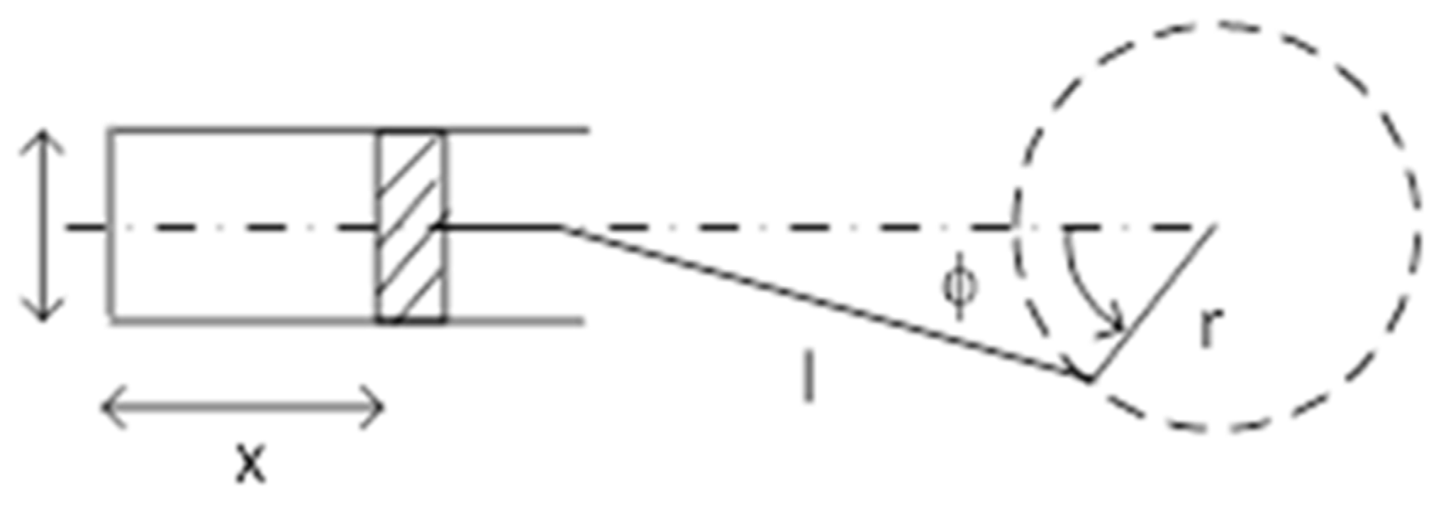
In Figure 5 a piston and crankshaft assembly is represented together with the connecting rod. The system parameters are defined as r, the radius of the crankshaft, l, the length of the connecting rod, and F, the rotation angle of the crankshaft. The diameter of the piston, d, and its horizontal displacement, x, are also defined.
The horizontal displacement of the piston is determined through rel. (1).
In this relation, an additional parameter is used, namely the connecting rod ratio l which is defined as
The piston’s velocity is calculated according rel. (3).
In this study, the torque to be provided by the motor is indirectly calculated through the power. The compression force exerted on the piston is given by the product of the pressure multiplied by the piston’s front area A.
The resulting mechanical power is defined by the product of the piston’s force by its velocity.
The torque is obtained by dividing the power by the angular velocity w.
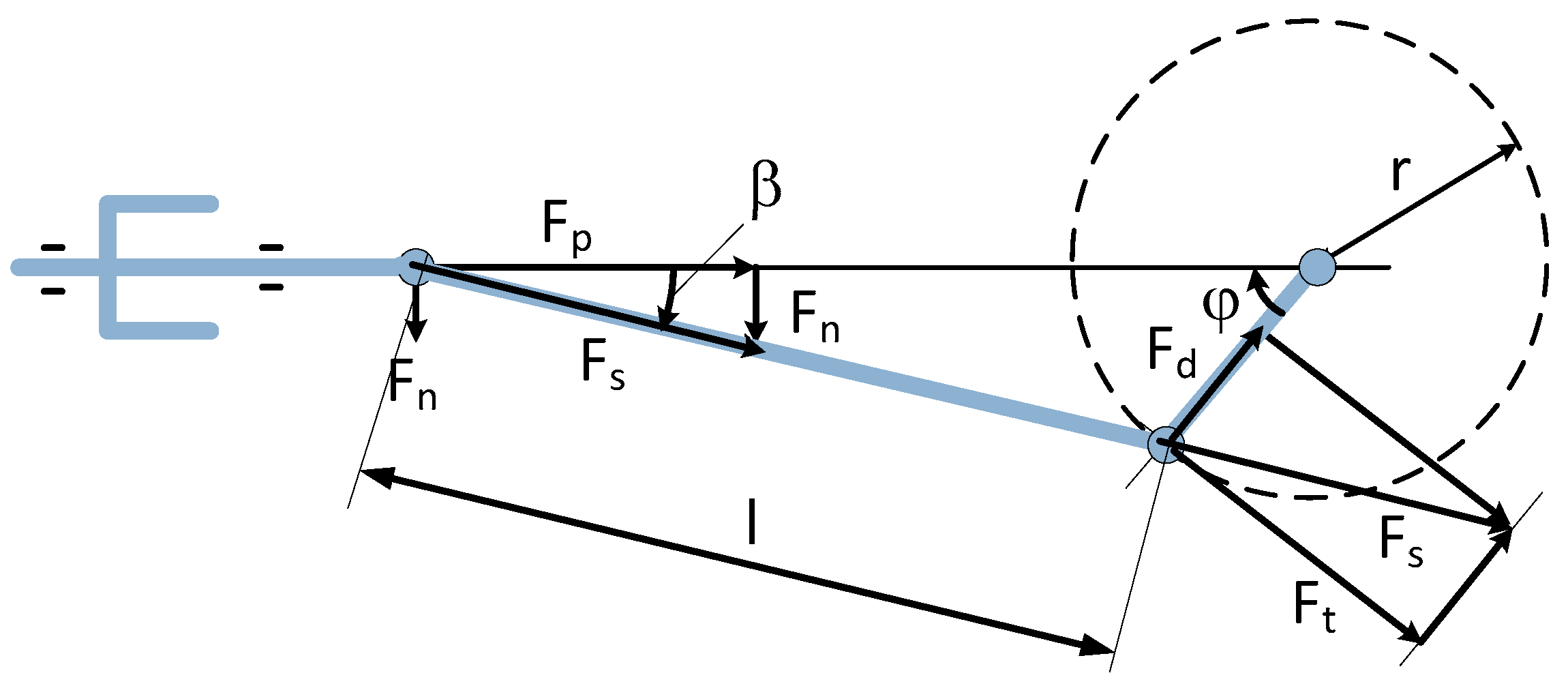
With the more detailed model given in Figure 6, the torque can be calculated without any consideration of the power and of the rotational speed [13]. As can be seen in the figure, the additional forces such as the force which is parallel to the connecting rod Fs, the tangential force Ft and the reaction force Fn are also defined. The torque on the crankshaft is given by rel. (7).
The tangential force Ft is given by (8).
The force transmitted through the connecting rod Fs is calculated with the help of the piston force Fp and the angle beta (9).
This angle is given by rel. (10).
In Figure 6, the reaction force Fn which is perpendicular to the piston’s movement is given as per (11).
For this system using a crankshaft and the two piston rods, a specific linear guiding element is needed which can hold the perpendicular reaction force at the bottom side of the piston. In this architecture, the piston rod cannot move inside the compression cylinder like in a normal piston assembly of a classical internal combustion engine. The consequence is that the total length of the compressor (in the direction of the piston’s displacement) is significantly increased.
Simulation Results
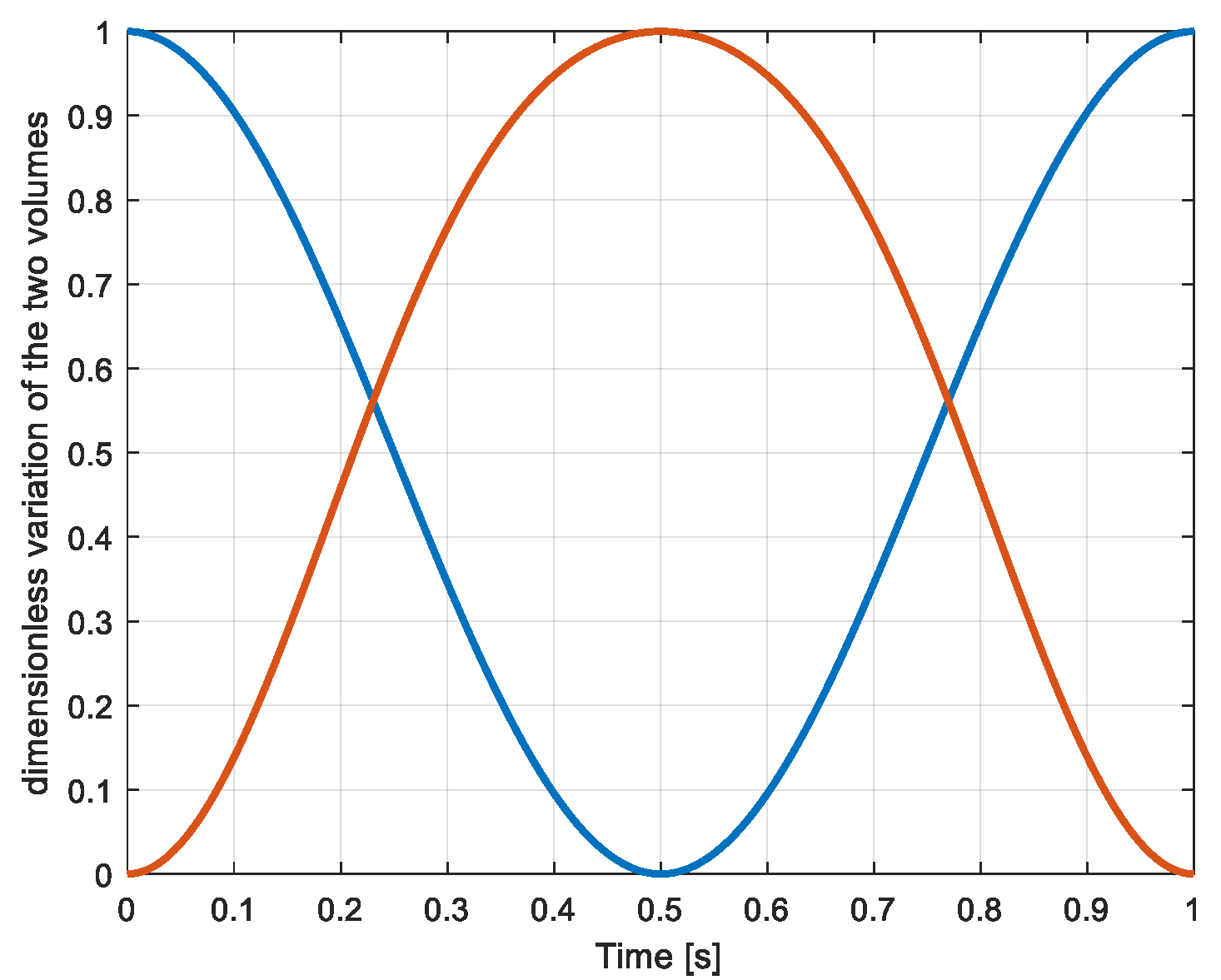
In Figure 7, the dimensionless evolution of the volumes of the compression cylinders is represented. The blue curve represents the evolution of the left cylinder while the red curve shows the variation of the volume of the right cylinder.
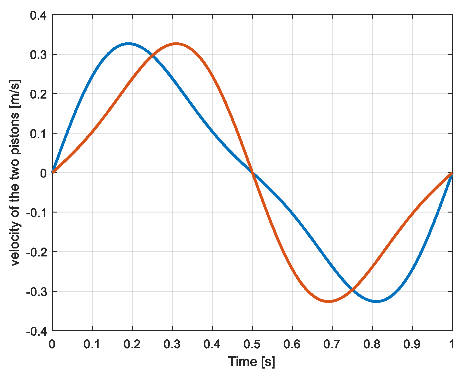
The curves represent already the asymmetric variation of the volumes of the left and right compression cylinders due to properties of the used crankshaft and 180° shifted connecting rods. The velocity of the two compressing pistons is given in Figure 8.
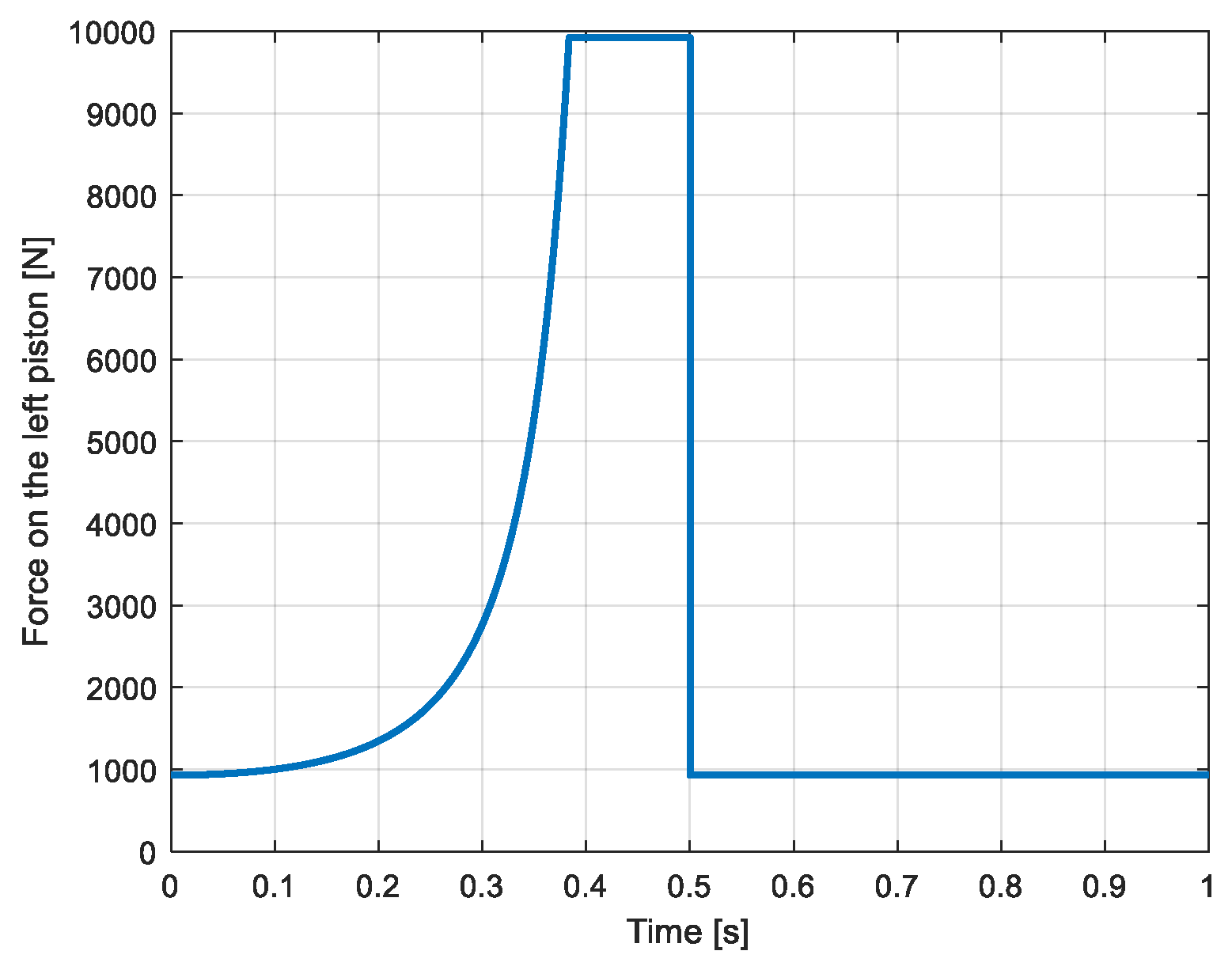
Figure 9 shows the evolution of the horizontal force of the left-side piston caused by the pressure in this cylinder. During the left-to-the-right stroke (0 to 0.5 s), the diagram shows the force related to the pressure rise from the inlet pressure (15 bar or 15 × 105 Pa) to the output pressure (160 bar or 160 × 105 Pa) when the exhaust valve opens and the compression cylinder is connected to the external reservoir. The elevation of the pressure is determined by a law of adiabatic evolution according to rel. (12). This assumption for the compression characteristic (adiabatic) is made in order to encompass the worst case but does not correspond to the real characteristics. In practice, the compression characteristic is nearer to an isothermal one, depending on the quality of the cooling of the compression cylinders.
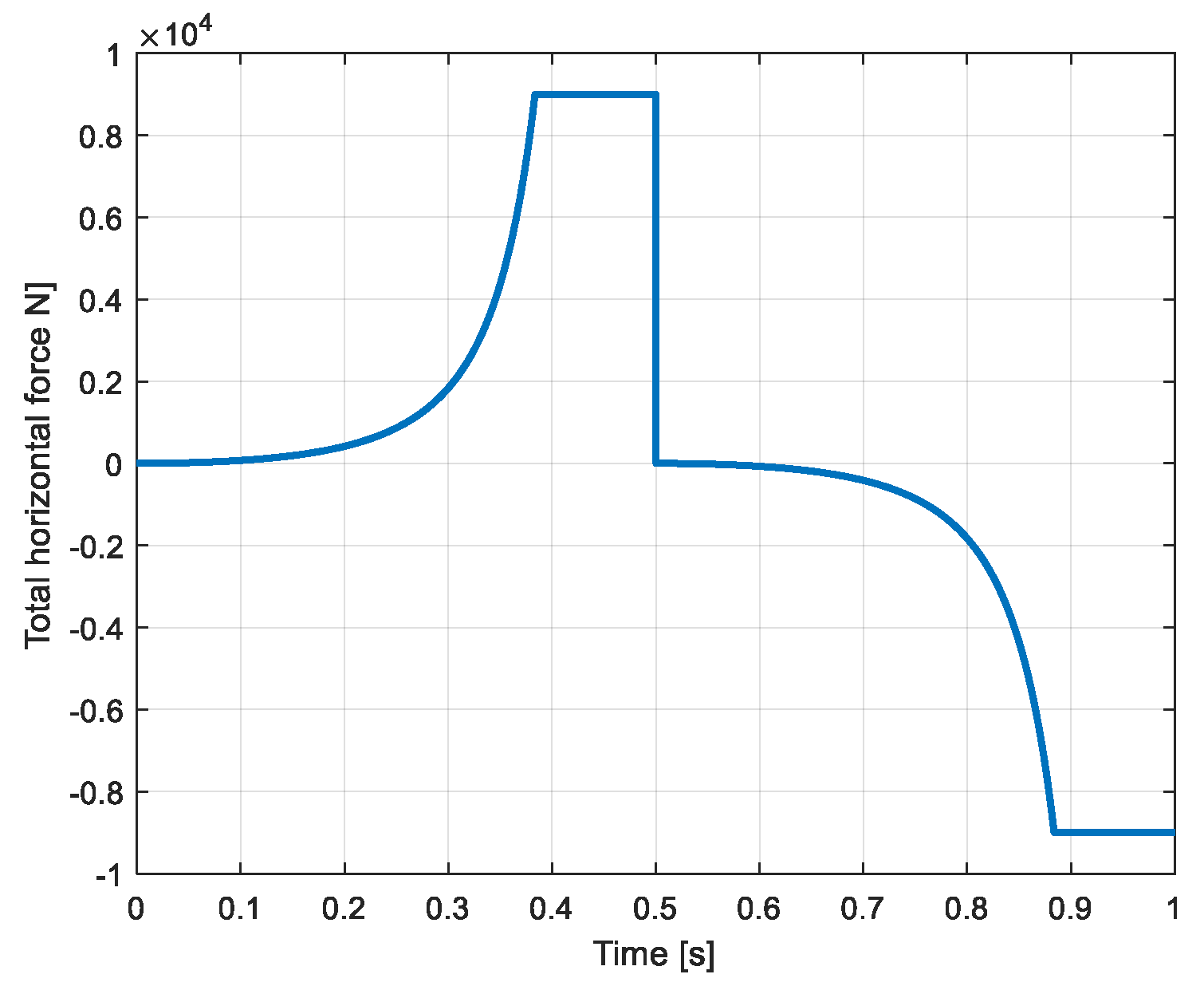
During the second half-period (0.5 s to 1 s) which corresponds to the right-to-the-left stroke, the pressure level in the same chamber corresponds to the intake pressure (15 bar or 15 × 105 Pa) when the intake valve opens The global force developed by the two pistons of the compression cylinders is represented in Figure 10. One can see that the force component due to the intake pressure compensates partially the compression force.
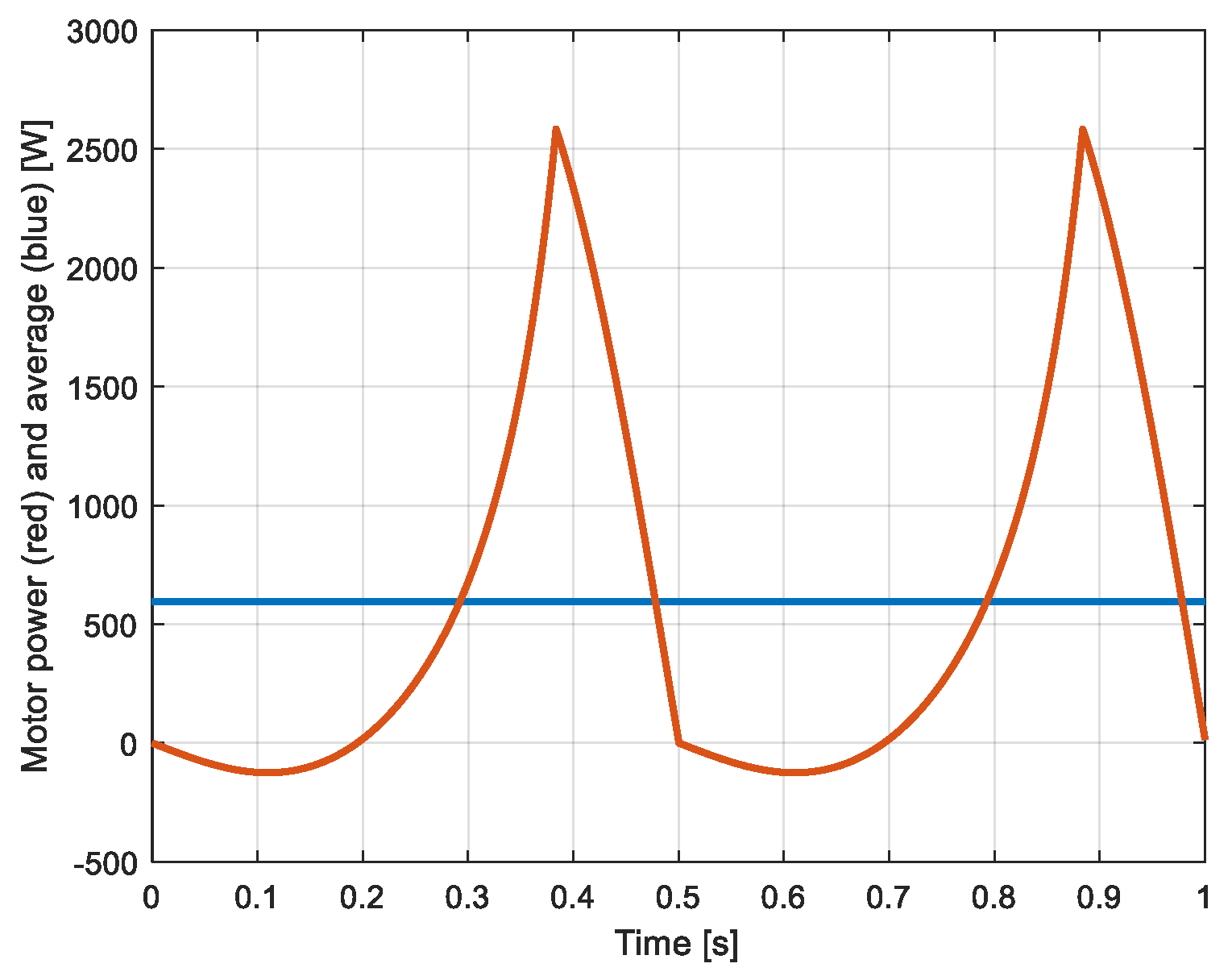
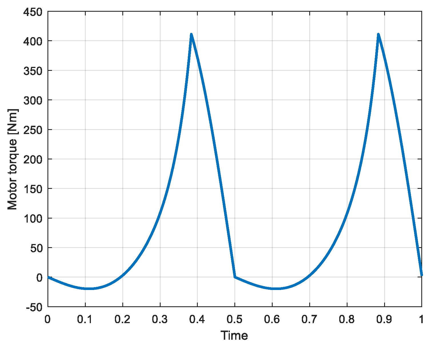
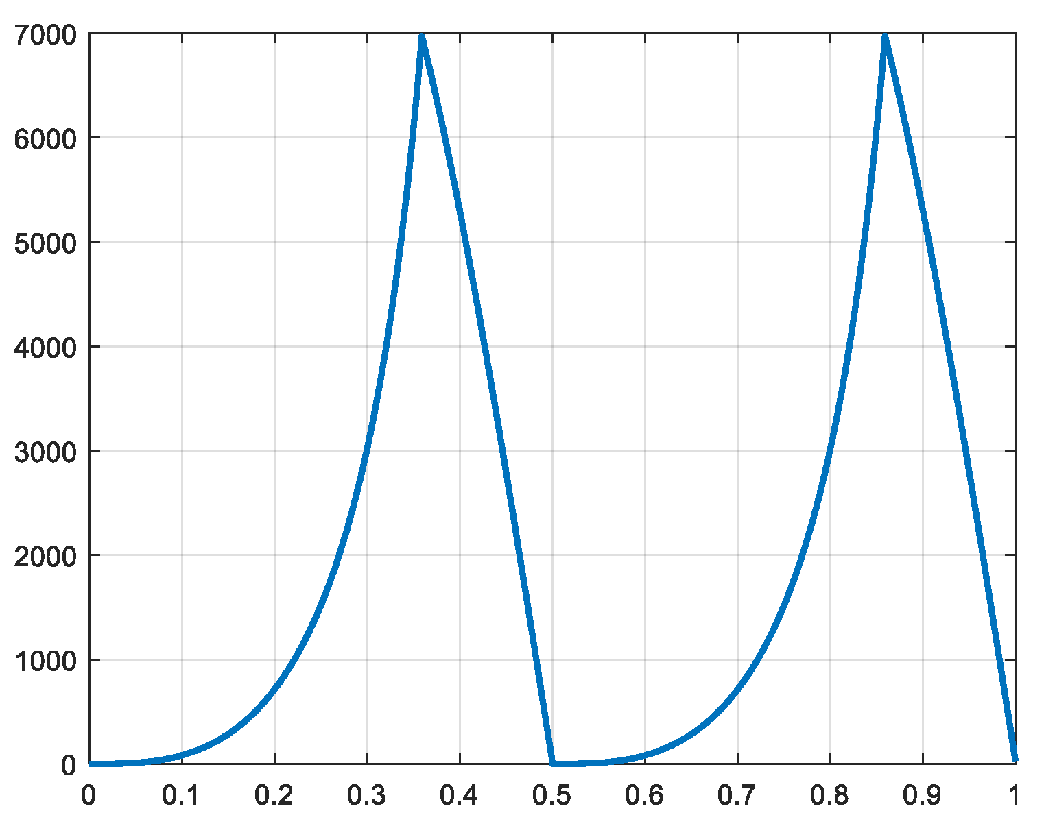
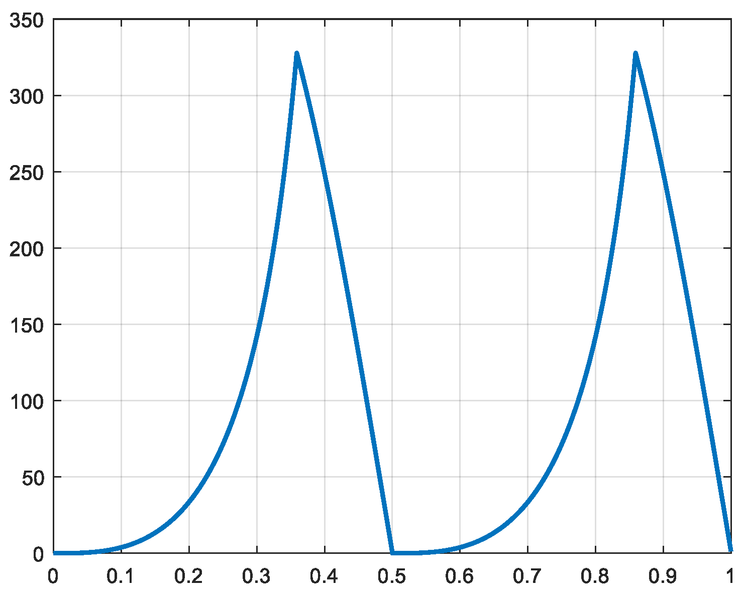
Figure 8 has shown the evolution of the piston’s velocity. This information is further used to calculate the power developed by the compression cylinders (Figure 11). This figure shows an interesting property of the system driven by a crankshaft and two connecting rods, where the power (as well as the torque, see Figure 12) takes a negative value at the beginning of the compression phenomena. This effect is due to the asymmetrical evolution of the displacement and speed in the left and right cylinders. From Figure 9 it is easy to see that the forces exerted on one piston during the time interval from 0 to 0.15 s have nearly the same value. On the right side of the piston the force corresponds to the compression force (curve between 0 and 0.5 s which rises slowly at the beginning of the stroke). On the left side of the same piston, the value of the force is given by the intake pressure, namely 15 bar and takes the constant value of around 1000 N. Then, when the two forces of that piston are nearly identical, the forces exerted on the other piston (right side piston) take the same values. The power contributions of each piston are determined by their forces multiplied by their velocities. From Figure 8, one can see that the velocities of the two pistons rise very differently during the time interval 0 to 0.25 s. As a result, there is a dominant negative power contribution of one of the pistons before the power of the other one rises strongly after around 0.25 s. In Figure 11, the abrupt change from a rising to decreasing value of the power corresponds to the instant where the compression force becomes constant when the exhaust valve opens. The corresponding power contribution is determined by an already strongly decreasing piston velocity. In reality, this specific effect of the power variation with negative value will certainly disappear due to the presence of non-negligible friction forces of the piston seals [14]. The value of the torque is obtained from the value of the power according to relation 6 and is represented in Figure 12.
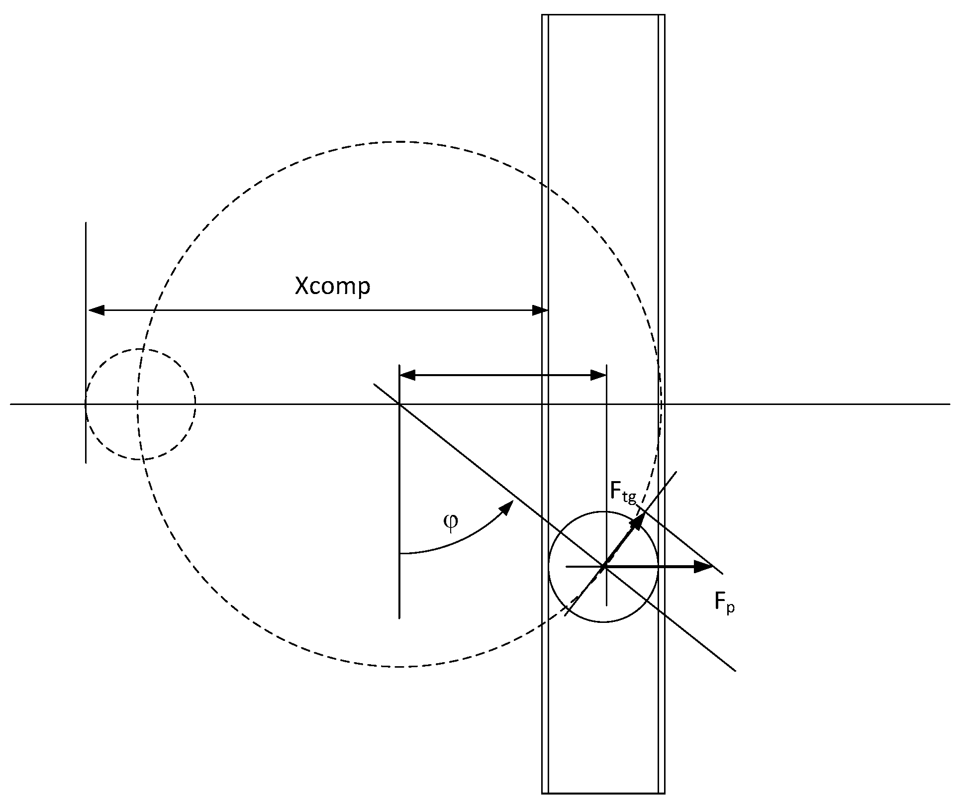
3.2. Forces and Torque Transmitted by the Scotch Yoke
The so-called Scotch Yoke has the property of directly transmitting the movement of a rotating rod within a vertical slot through a specific bearing. For determining the waveform of the torque to be developed by the electric motor, the kinematics of the mechanism are analyzed. From the diagram of Figure 13 the following variables are defined:
Compression shift xcomp:
Tangential force Ftg
The tangential force is represented in Figure 14 and results in a torque (Figure 15) with a similar waveform given by
The rotor of the mechanism is rotating at a constant angular velocity, namely 6.28 rad/s. The power value defined at the level of the rotating shaft is defined by
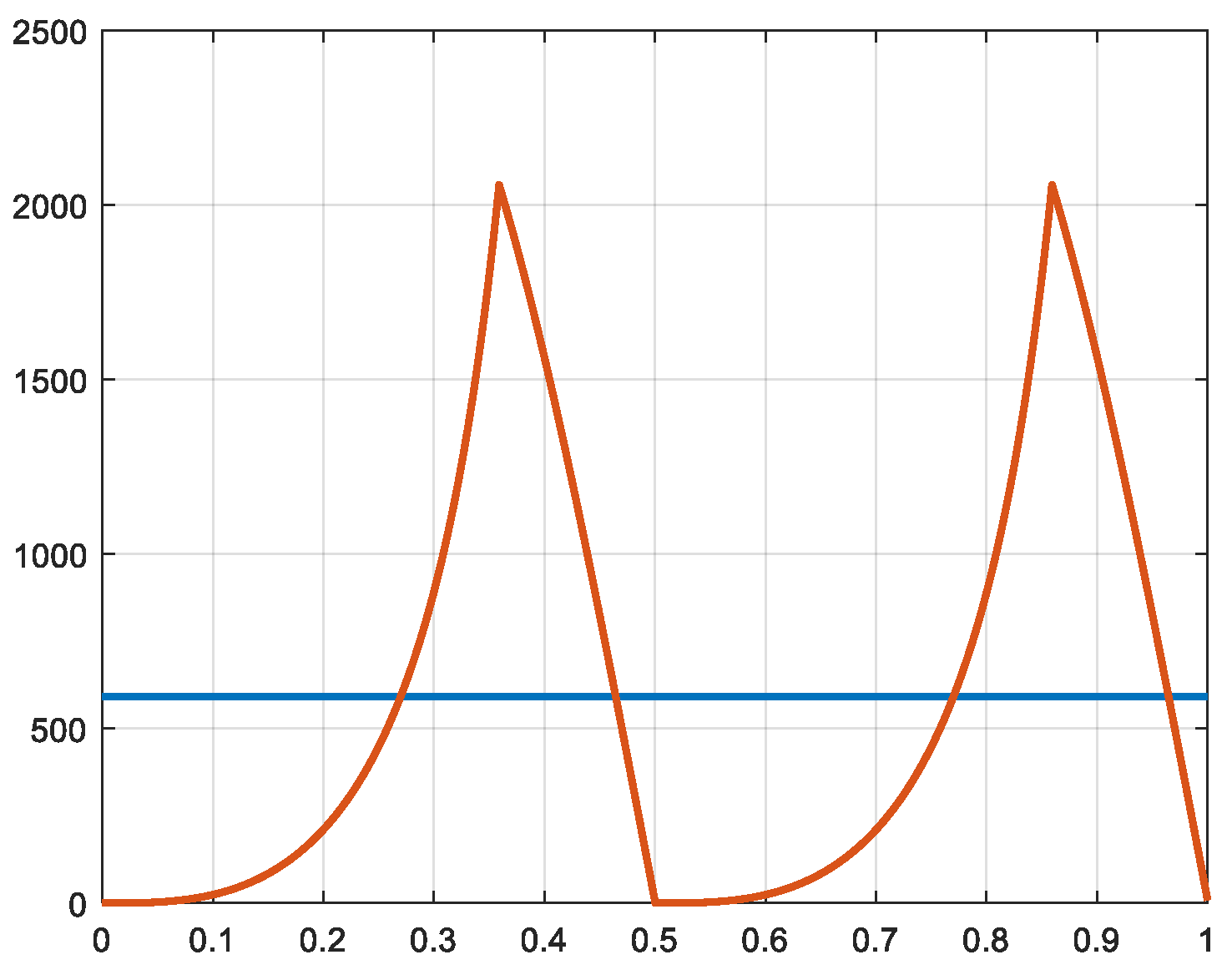
The profile of the power is identical to the waveform of the tangential force and of the torque and is represented in Figure 16. On the same representation, the average value of the power is represented. One can see that the specific effect of the negative value of the power and torque shown before its strong positive increase of the first mechanism (crankshaft and two connecting rods) has disappeared. This is due to the fact that the velocities of the two pistons moved by the Scotch Yoke are of identical magnitudes. For simplification of the conception of the new system, the losses in the electric motor as the losses of the power converter are neglected. As a consequence, the profile of the power is identical at the level of the DC link of the feeding power converter.
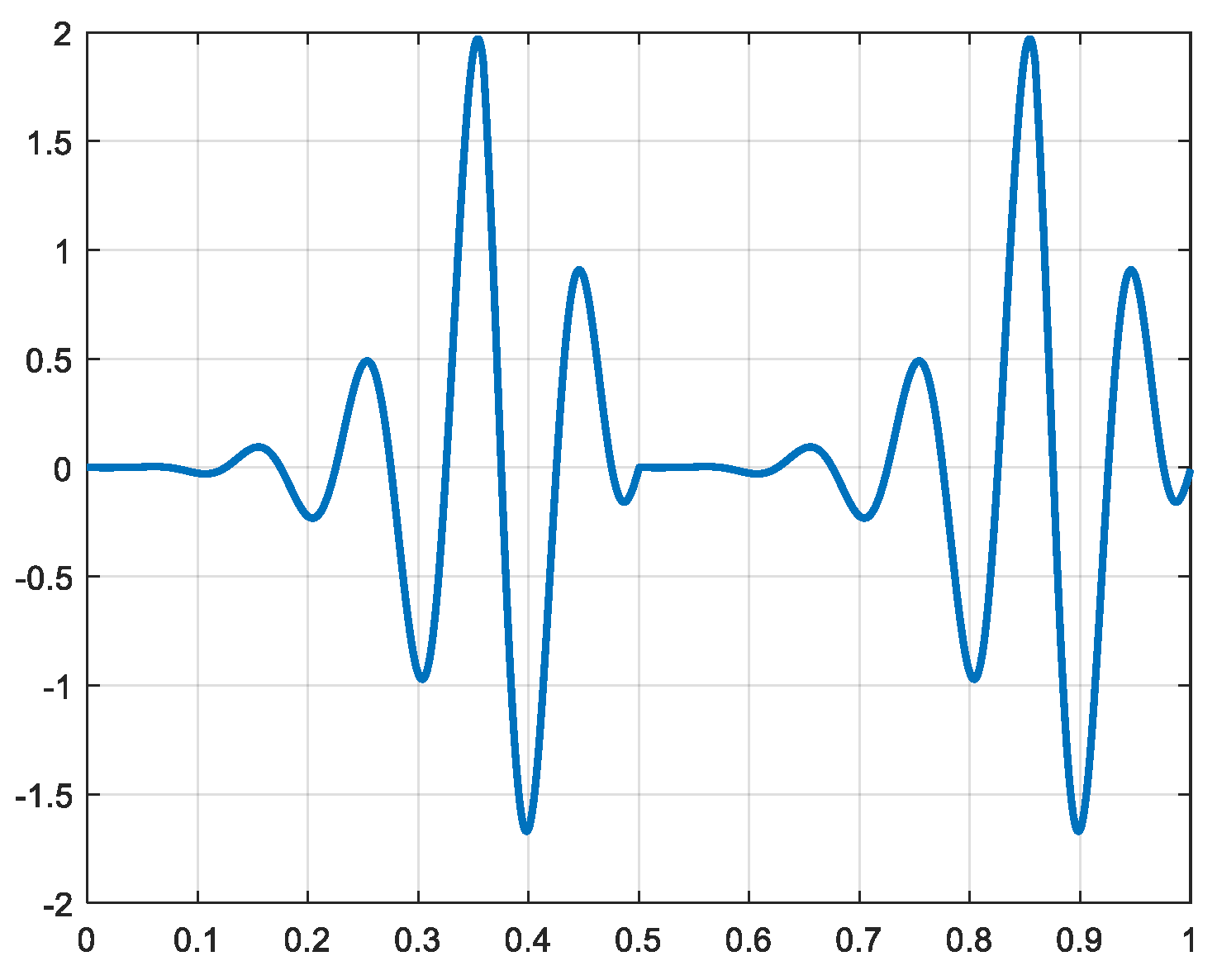
By considering an electric motor able to provide the high fluctuations of the power, its rated power is chosen at half of the maximum power to be provided. The size of this motor and the torque it should provide can be maintained at reasonable values by inserting a gear ratio between the motor and the rotor of the Scotch Yoke mechanism. This adaptation can be realized with a tooth-belt and toothed wheels. A first design is performed with a gear ratio of 1/10. When the rotor of the mechanism rotates at w = 6.28, the motor must have a nominal speed of 600 RPM. The current of this motor is represented in Figure 17.
4. The Electric Drive with an Active Power Smoothing Circuit
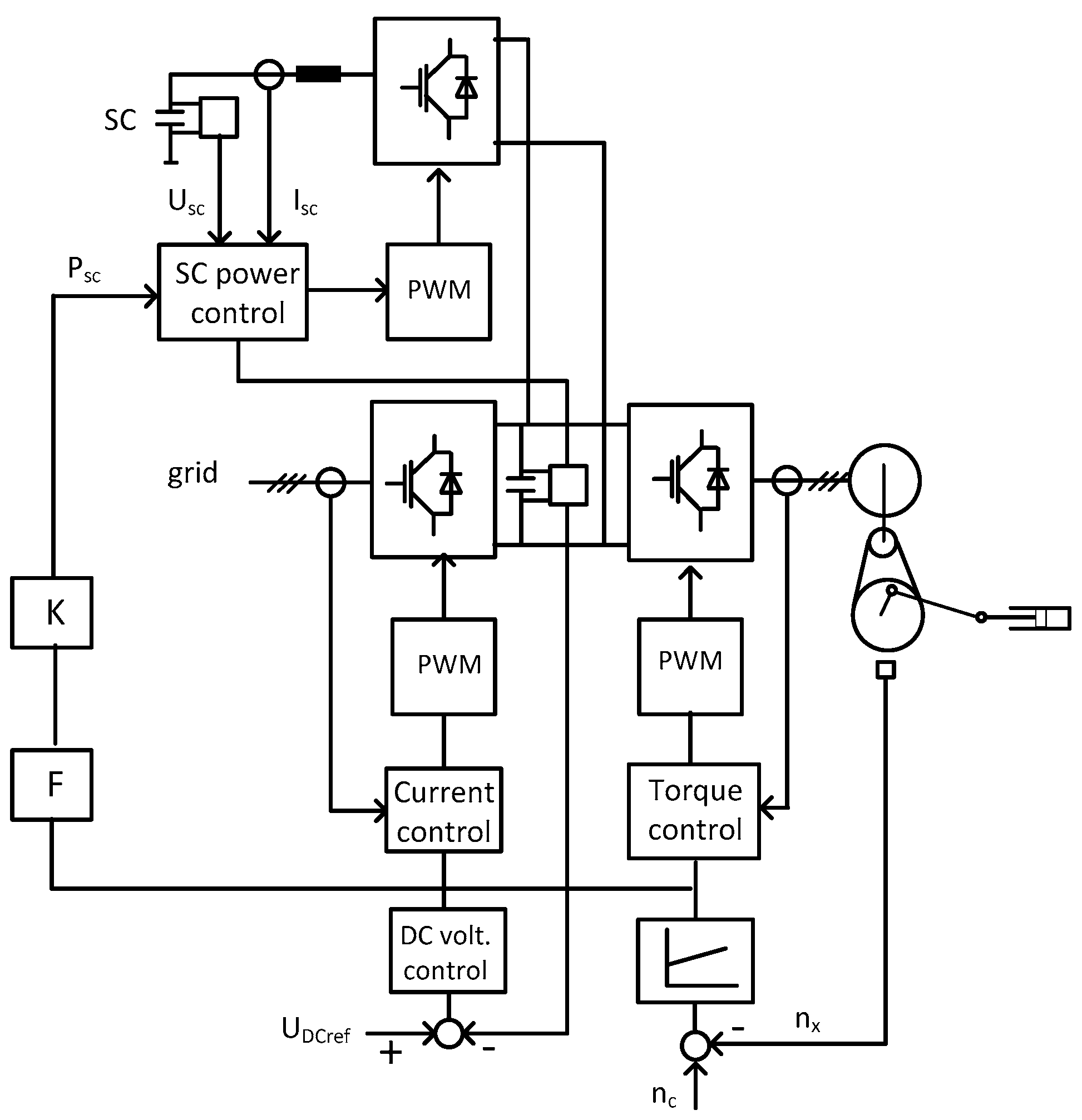
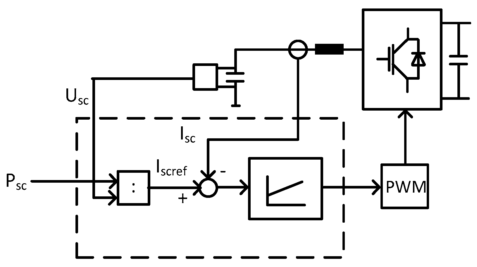
The waveforms of power and torque needed for the activation of the compression cylinders are represented in Figure 15 and Figure 16. These waveforms can be followed by a modern electric drive, for example a permanent magnet synchronous motor fed by a fast-switching voltage source inverter. The power, however, should not be taken directly from the feeding grid where the power level is normally smooth. To obtain at the line side of the frequency converter a fully smoothed power, a power compensating storage device is added and interconnected at the level of the intermediary DC circuit of the converter.
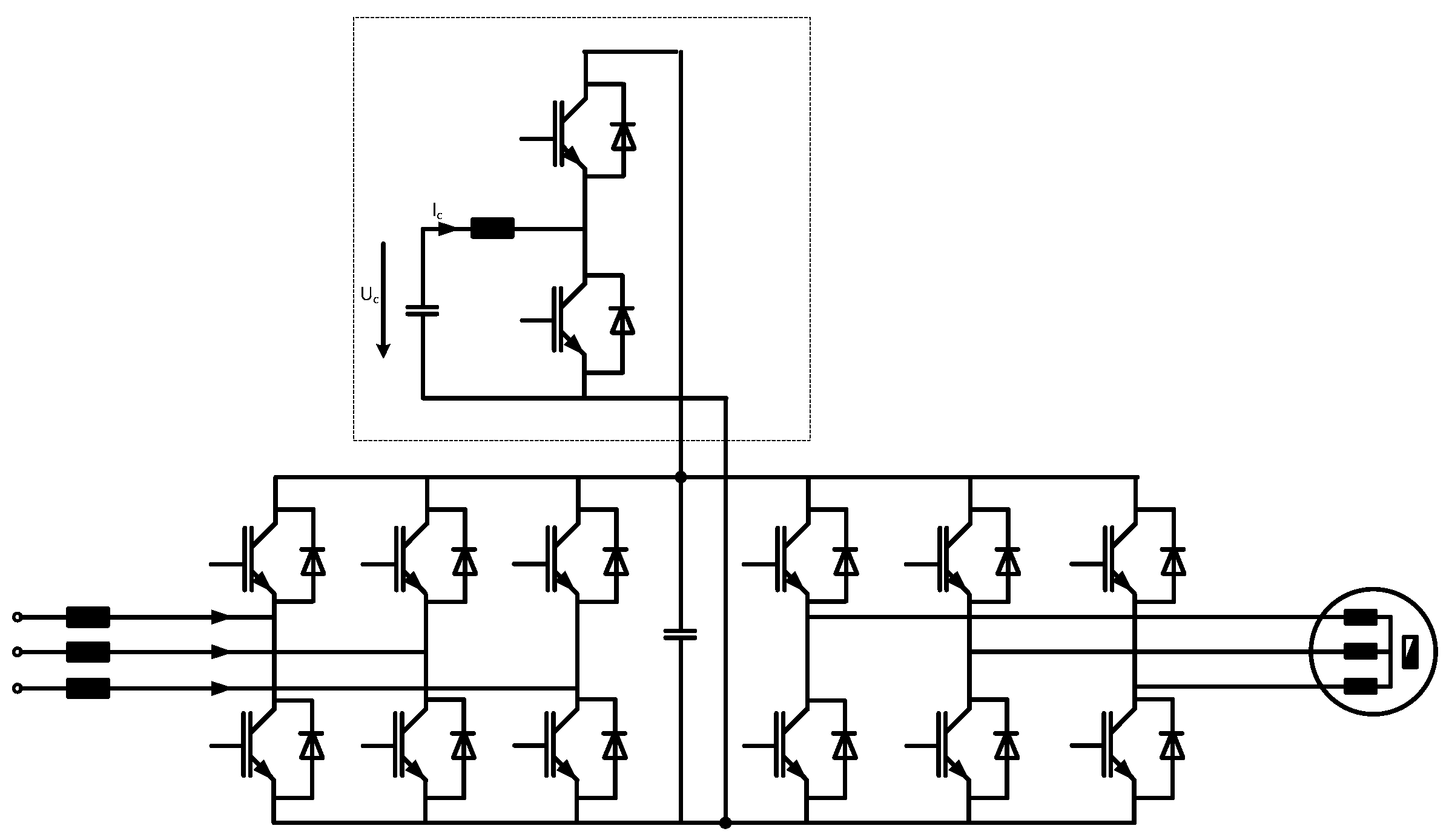
The active compensation device is composed of a capacitor which is periodically charged and discharged through a dedicated DC-DC conversion stage. The complete circuit of the drive fed by the voltage source converter and the active compensation circuit is represented in Figure 18. A more detailed scheme of the power electronic circuit is given in Figure 19.
The power converter feeding the motor is composed of two back-to-back connected voltage source converters. The converter at the motor-side has a torque and speed controller, and at the line side a line current control with a superimposed DC-link voltage control (Figure 18).
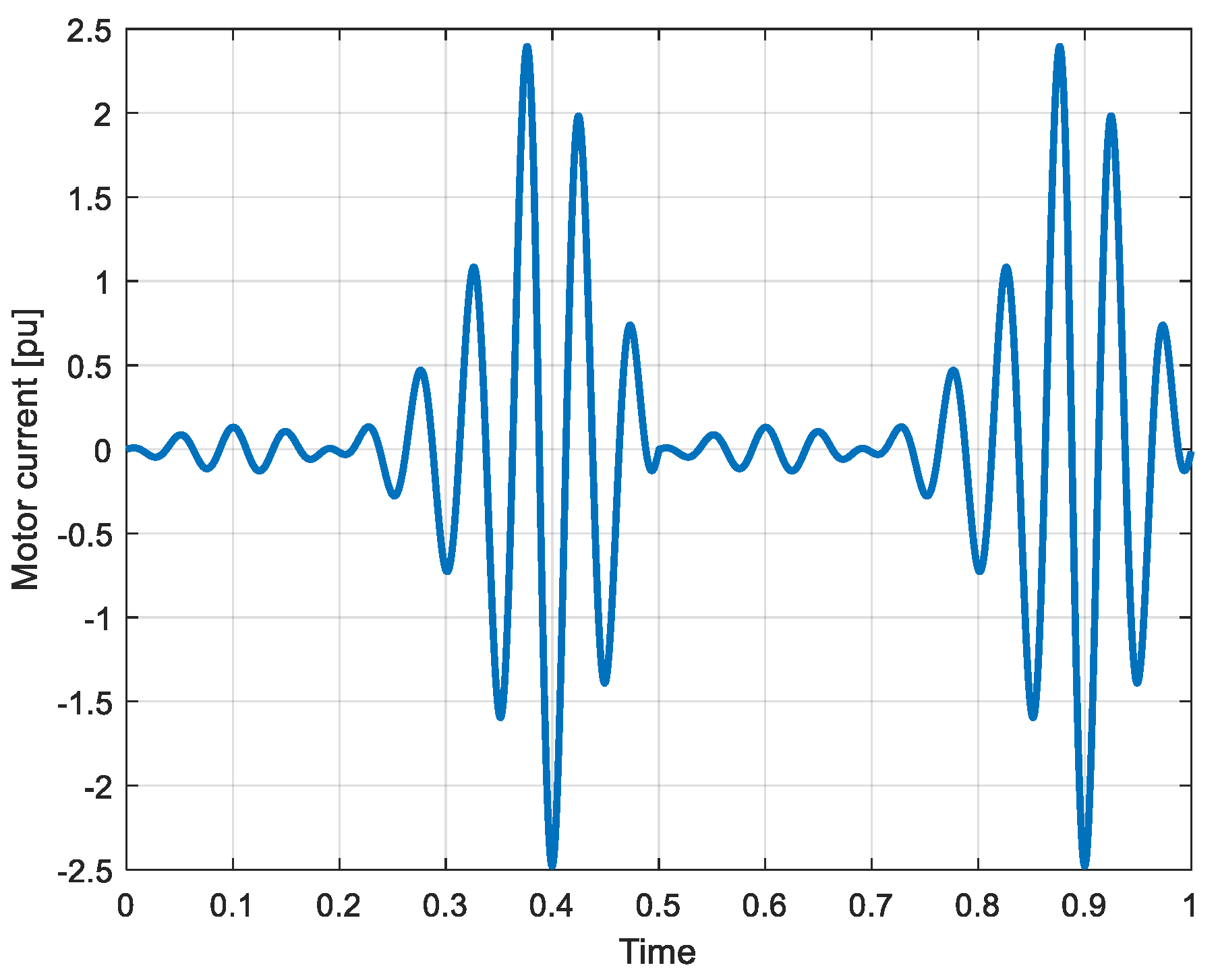
According to the very specific waveform of the needed power and torque for the compression stages (Figure 15 and Figure 16), the current in the phases of the driving motor shows very strong variations. These variations and especially their corresponding low frequency can be seen in Figure 20. The represented waveform of the current corresponds in this figure to a drive with a higher gear ratio, as was represented in Figure 17.
4.1. The Active Power Compensator
The active power compensator is composed of a bidirectional step-down and step-up chopper circuit interfaced with the variable voltage storage capacitor through a smoothing inductor and is connected directly to the DC link of the frequency converter (Figure 19).
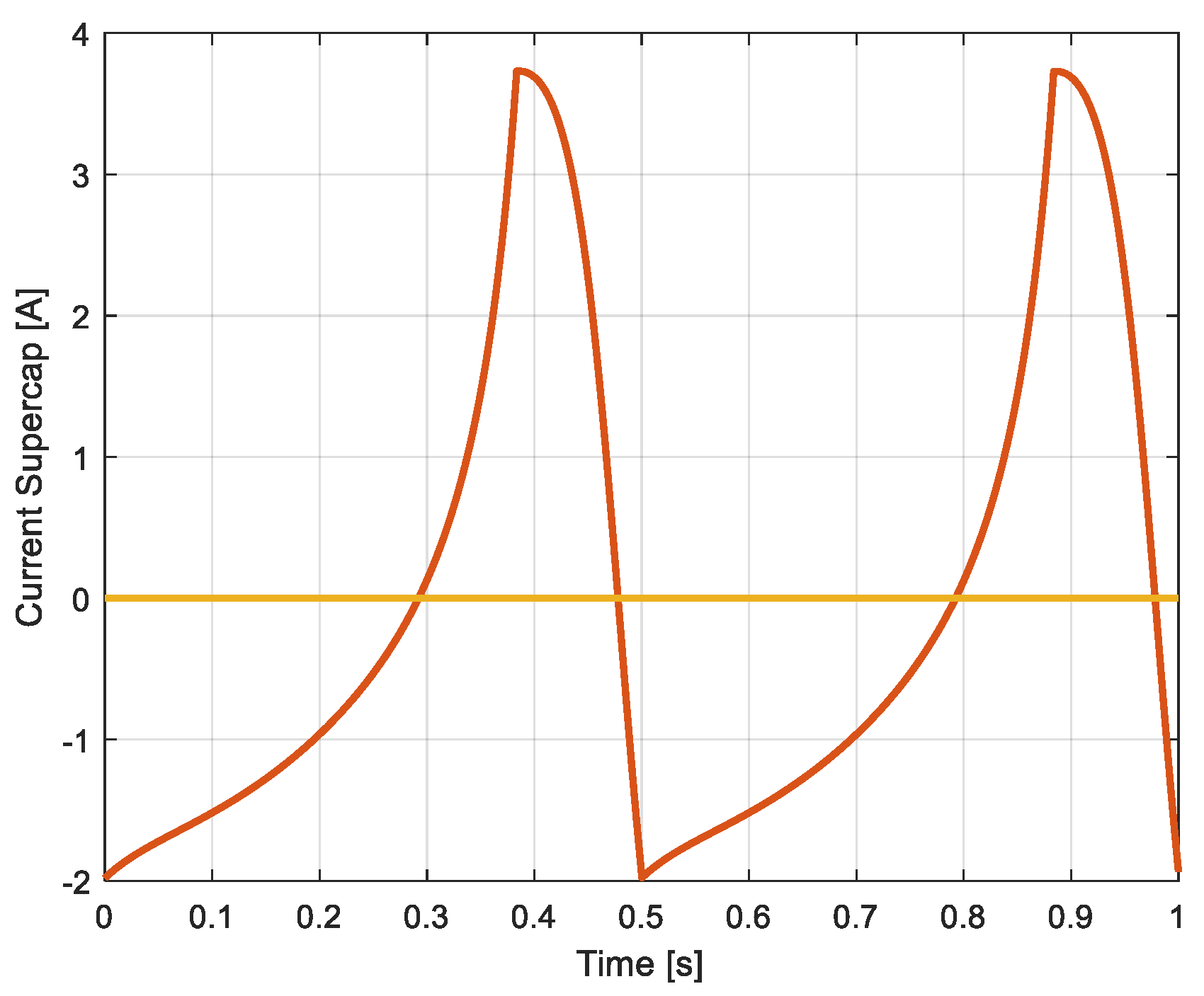
The control of the active power compensator can be seen globally in Figure 18. This control is based on the principle of using a feed-forward power control signal obtained from the output of the speed controller at the motor side. Then, the control of the capacitor current is realized, taking in account the actual value of the capacitor voltage. The capacitor’s current reference is obtained by dividing the compensation power reference by the capacitor voltage. The detailed control circuit of the compensation capacitor is given in Figure 21.
4.2. Design of the Storage Capacitor
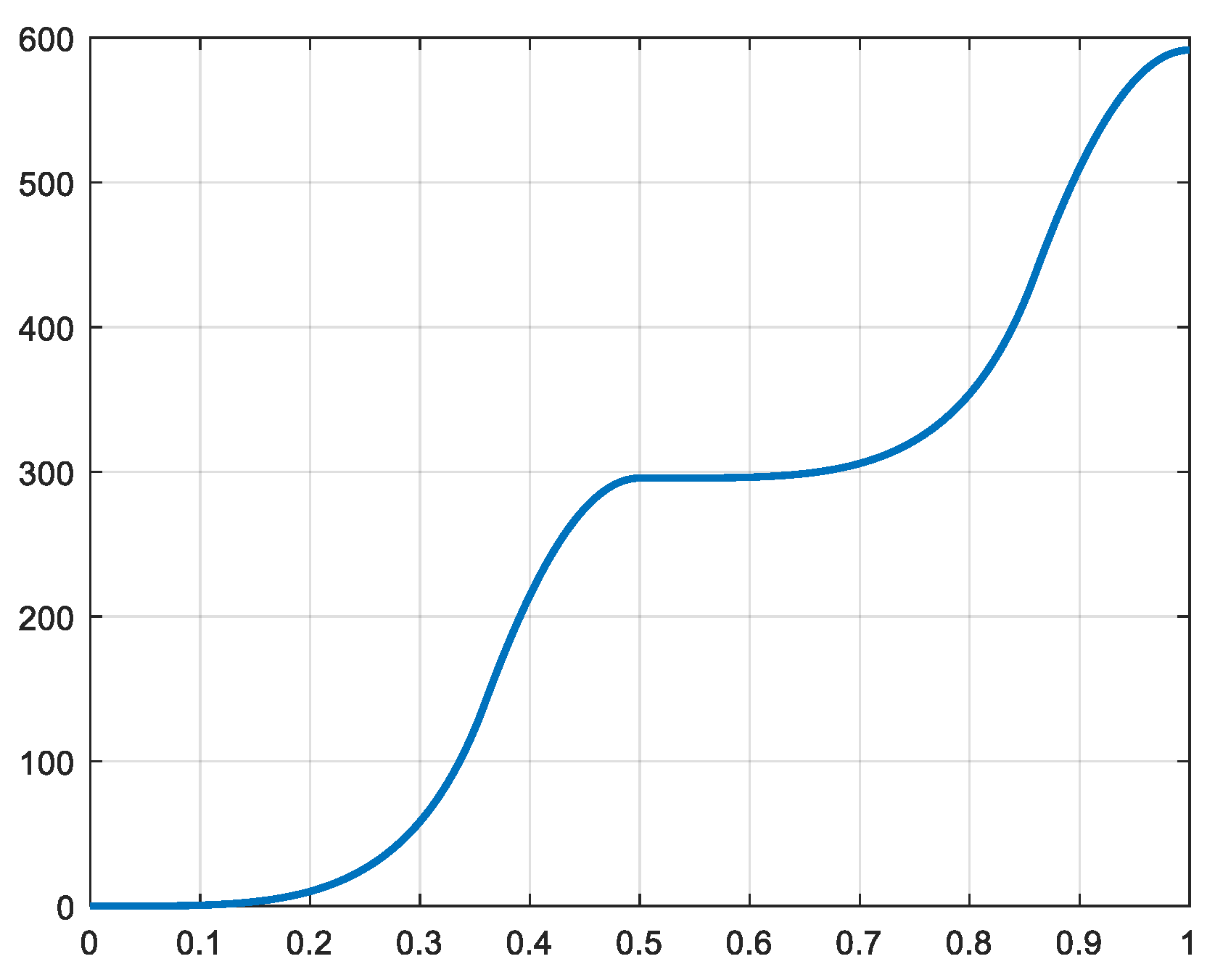
The design of the storage capacitor is based on the amount of energy to be stored and un-stored in it [15,16]. Figure 22 illustrates the time-integral of the exchanged power, corresponding to the total energy flow.
During one cycle of the power which corresponds to one half of the revolution of the crankshaft, the energy variation is of 298 J. During this variation, the storage capacitor is charged and discharged to obtain a smooth average value at the level of the power exchange with the grid. The amounts of charged energy and of the discharged one are identic, and are equal to the half of the energy variation mentioned before.
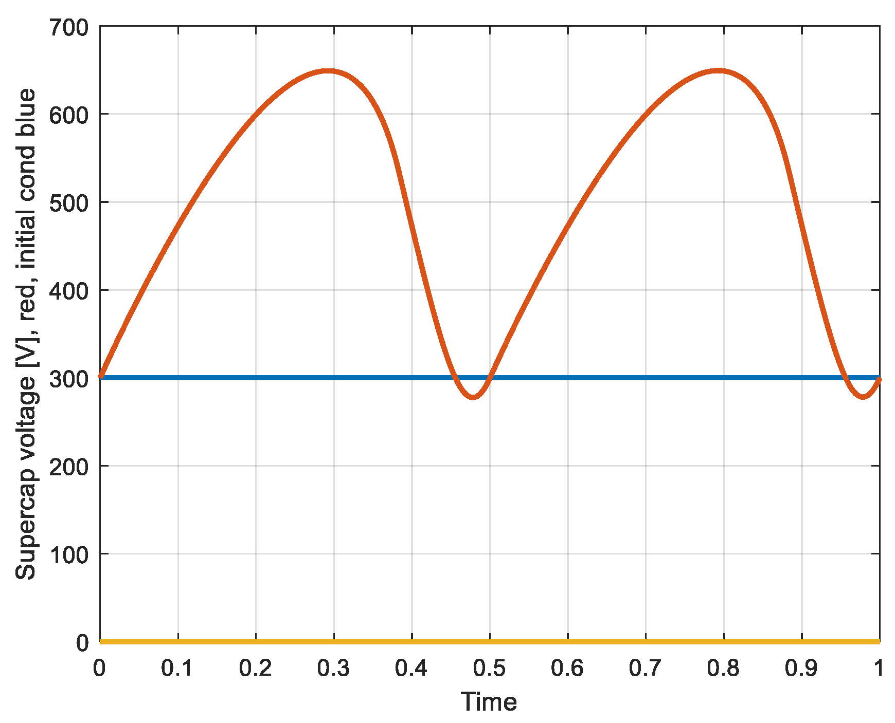
The domain of use of the capacitor in terms of its discharge ratio [15,17] can be calculated. The design criterion of this element corresponds to the definition of its corresponding voltage variation. The capacitor is discharged from its 100% value down to a value of 50%, starting from a physical value of 600 V.
The total energy content of the fully charged capacitor is [17]:
For a voltage variation from 100% to 50% the energy extracted is
Then, the value of the capacitor is defined from
or 1100 mF
5. Conclusions
A new drive system for a Hydrogen compressor has been studied with the goal to increase the energy efficiency of a conventional gas booster. These boosters are used in low power storage facilities or in refueling stations for Hydrogen powered cars. Such gas boosters are currently driven by pneumatic motors which are well known for their very poor energy efficiency. The new drive system is realized using an electric motor powered by a power electronic frequency converter allowing a variable rotational speed.
The transmission of the rotational motion of the motor to the linear motion of the compression pistons can be realized with two different coupling mechanisms. The first presented system uses a conventional crankshaft and two piston rods. The second studied system is based on the use of a so-called Scotch-Yoke, which simplifies the realization and limits the external space and dimensions of the complete compressor.
The waveforms of the two systems as their forces, torques and power are simulated for a compressor which realizes a pressure shift from 15 bar to 160 bar.
A strongly fluctuating power in the driving motor appears due to the strong variation of the pressure in the compression cylinders. For the compensation of these fluctuations a dedicated smoothing equipment is proposed using an active power compensator interfaced to the DC link of the frequency converter; this avoids the power fluctuations being reflected in the connected grid. This auxiliary smoothing device is based on energy storage in a capacitor in which voltage is periodically varied.
On the basis of an existing compressor, the main characteristics of the needed equipment as driving motor or active power compensator have been specified.
Funding
The research received no external funding.
Conflicts of Interest
The authors declare no conflict of interest.
References
- Züttel, A. Materials for hydrogen storage. Mater. Today 2003, 6, 24–33. [Google Scholar] [CrossRef]
- Ligen, Y.; Vrubel, H.; Arlettaz, J.; Girault, H. Experimental correlations and integration of gas boosters in a hydrogen refueling station. Int. J. Hydrogen Energy 2020, 45, 16663–16671. [Google Scholar] [CrossRef]
- Fazle-Kibria, A.K.M.; Mo, Y.H.; Nahm, K.S.; Yun, M.H. Electrochemical hydrogen storage behaviors of CVD, AD, and LA grown carbon nanotubes in KOH medium. Int. J. Hydrogen Energy 2001, 26, 823–829. [Google Scholar] [CrossRef]
- Poirier, E.; Chahine, R.; Bose, T.K. Hydrogen adsorption in carbon nanostructures. Int. J. Hdrogen Energy 2001, 26, 831–835. [Google Scholar] [CrossRef]
- Grasemann, M.; Laurenczy, G. Formic acid as a hydrogen source: Recent developments and future trends. Energy Environ. Sci. 2012, 5, 8171–8181. [Google Scholar] [CrossRef]
- Truglia, V.G. High-Efficiency Engine Driven by Pressurized Air or Other Compressible Gases. U.S. Patent 9.677.400 B2, 13 June 2017. [Google Scholar]
- Negre, G.; Negre, C. Engine with an Active Mono-Enery and/or Bi-Energy Chamber with Compressed Air and/or Additional Energy and Thermodynamic Cycle Thereof. U.S. Patent 7,469,527 B2, 30 December 2008. [Google Scholar]
- Rufer, A. A High efficiency pneumatic drive system using vane-type semi-rotary actuators. Facta Univ. Ser. Electron. Energetics 2021, 34, 415–433. [Google Scholar] [CrossRef]
- Rufer, A. Pneumatic Cylinder Assembly with Enhanced Energetic Efficiency. PCT Patent Application PCT/CH2021000002, 4 May 2021. [Google Scholar]
- Shi, Y.; Cai, M.; Xu, W.; Lü, J. Flow Characteristics of Expansion Energy Used Pneumatic Booster. Chin. J. Mech. Eng. 2012, 25, 889–896. [Google Scholar] [CrossRef]
- Rufer, A. A Pneumatic Driven Hydrogen Compressor with Reduced Air Consumption. Patent Appl. WO 2022/232953, PCT/CH2021/00002, 2021. [Google Scholar]
- Arakelian, V.; Le Baron, J.P.; Mkrtchyan, M. Design of Scotch yoke mechanisms with improved driving dynamics. Proc. Inst. Mech. Eng. Part K J. Multi-Body Dyn. 2016, 230, 379–386. [Google Scholar] [CrossRef]
- Martin, G.H. Kinematics and Dynamics of Machines; Mc Graw Hill Series in Mechanical Engineering; Waveland Press: Long Grove, IL, USA, 2002. [Google Scholar]
- Nagar, P.; Miers, S. Friction between Piston and Cylinder of an IC Engine: A Review. In Proceedings of the SAE 2011 World Congress & Exhibition, Detroit, MI, USA, 12–14 April 2011. SAE Technical Paper 2011-01-1405. [Google Scholar] [CrossRef]
- Rufer, A. Energy Storage—Systems and Components; CRC Press, Taylor and Francis Group: Boca Raton, FL, USA, 2018. [Google Scholar]
- Rufer, A. Design and Control of a KE (Kinetic Energy)—Compensated Gravitational Energy Storage System. In Proceedings of the EPE ECCE Europe 2020, European Conference on Power Electronics and Applications, Lyon, France, 7–11 September 2020. [Google Scholar]
- Barrade, P.; Rufer, A. Current capability and power density of supercapacitors: Considerations on energy efficiency. In European Conference on Power Electronics and Applications, EPE 2003; EPE Association: Brussels, Belgium, 2003; ISBN 90-75815-07-7. [Google Scholar]
Figure 1.
Simplified representation of a Hydrogen storage system.

Figure 2.
Example of a Hydrogen generation and storage facility.

Figure 3.
Pressure-volume diagram of pressurized air work and expansion.

Figure 4.
The different architectures of the gas booster.

Figure 5.
Piston, crankshaft and connecting rod.

Figure 6.
Definition of the forces used for the calculation of the mechanical torque and the perpendicular reaction.
Figure 6.
Definition of the forces used for the calculation of the mechanical torque and the perpendicular reaction.

Figure 7.
Dimension-less variation of the volumes of the compression cylinders. (red: left, blue: right).
Figure 7.
Dimension-less variation of the volumes of the compression cylinders. (red: left, blue: right).

Figure 8.
Velocity of the pistons (m/s). (red: left, blue: right).

Figure 9.
Force developed by the left piston (N).

Figure 10.
Total force (horizontal) (N).

Figure 11.
Power received by the two pistons (W). red: power, blue: average value).

Figure 12.
Torque developed (crank shaft) (Nm).

Figure 13.
Definition of variables of the Scotch Yoke mechanism.

Figure 14.
Tangential force of the Scotch Yoke mechanism [N].

Figure 15.
Load torque transmitted to the rotor [Nm].

Figure 16.
Power (red) and average value (blue) (W).

Figure 17.
Current in one phase of the motor (p.u.).

Figure 18.
Schematic diagram of the electric drive system with active power compensation circuit.

Figure 19.
Detailed scheme of the power electronic converter with active power compensation.

Figure 20.
Current in one phase of the motor (p.u).

Figure 21.
Detailed scheme of the control of the compensation Capacitor.

Figure 22.
Energy flow from the motor to the compression cylinders (J).

Figure 23.
Current exchanged with the compensator capacitor(A).

Figure 24.
Voltage of the storage capacitor (V).

Disclaimer/Publisher’s Note: The statements, opinions and data contained in all publications are solely those of the individual author(s) and contributor(s) and not of MDPI and/or the editor(s). MDPI and/or the editor(s) disclaim responsibility for any injury to people or property resulting from any ideas, methods, instructions or products referred to in the content. |
© 2023 by the author. Licensee MDPI, Basel, Switzerland. This article is an open access article distributed under the terms and conditions of the Creative Commons Attribution (CC BY) license (https://creativecommons.org/licenses/by/4.0/).
Share and Cite
MDPI and ACS Style
Rufer, A. Increasing the Energy Efficiency of Gas Boosters for Hydrogen Storage and for Refueling Stations. Energies 2023, 16, 1763. https://doi.org/10.3390/en16041763
AMA Style
Rufer A. Increasing the Energy Efficiency of Gas Boosters for Hydrogen Storage and for Refueling Stations. Energies. 2023; 16(4):1763. https://doi.org/10.3390/en16041763
Chicago/Turabian StyleRufer, Alfred. 2023. "Increasing the Energy Efficiency of Gas Boosters for Hydrogen Storage and for Refueling Stations" Energies 16, no. 4: 1763. https://doi.org/10.3390/en16041763
Note that from the first issue of 2016, this journal uses article numbers instead of page numbers. See further details here.