1. Introduction
Photovoltaic (PV) technology is currently one of the most widely used technologies for producing renewable electricity with 20.6% of the 6523 TWh renewable electricity generation worldwide in 2018 [
1]. During the period 2009–2019, photovoltaic technology was the fastest increasing renewable energy technology, with an average cumulative increase of 36% of grid-connected installation [
1].
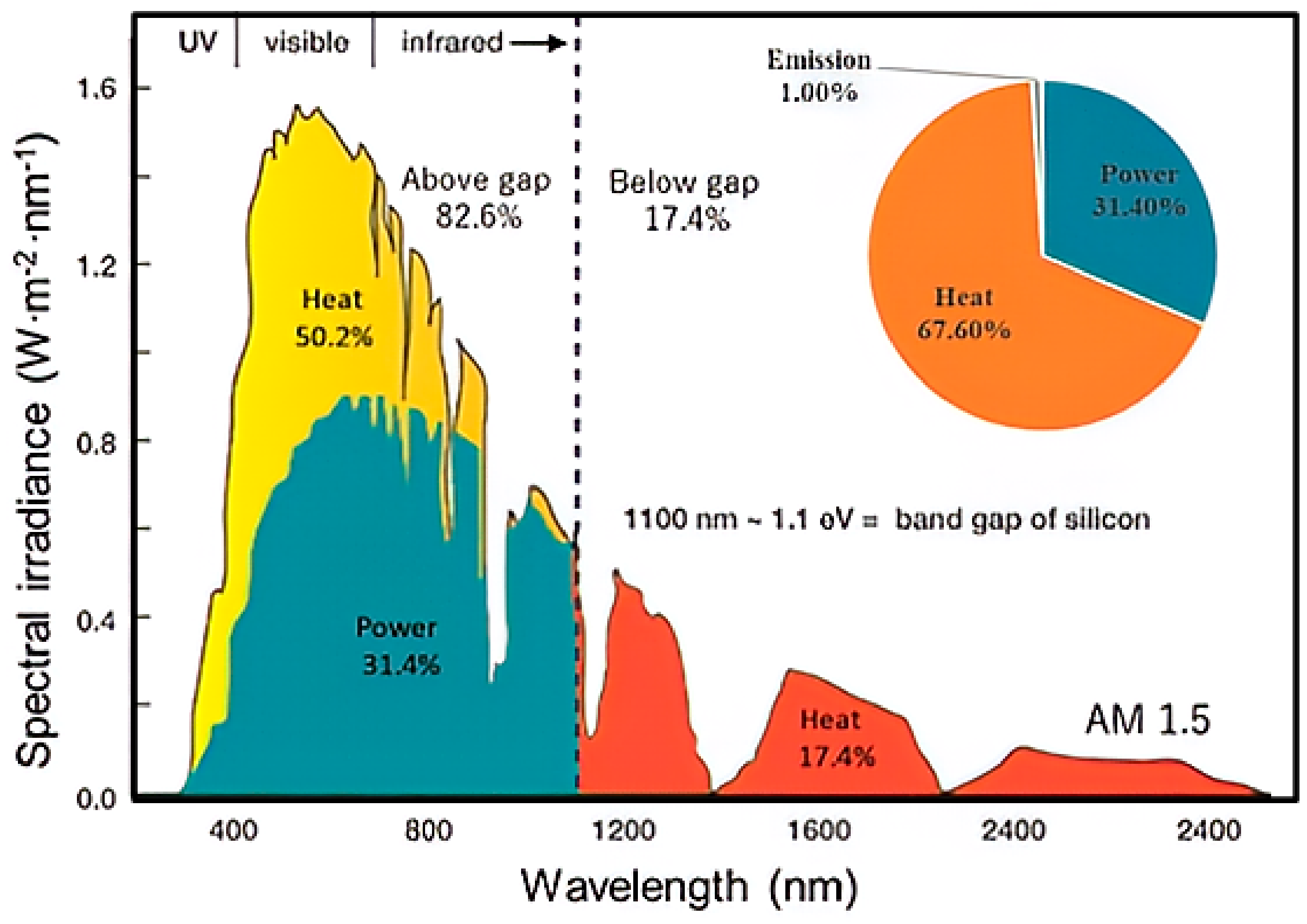
The conversion of solar radiation directly into electricity with the highest possible efficiency is a research topic of great interest in the scientific community. The PV conversion for a simple Si-based p-n junction is, however, limited by the theoretical Shokley–Queiser limit: only a maximum of 31% of the non-concentrated solar radiation can be converted into electricity [
2]. As shown in
Figure 1 and proposed by Li et al. [
3], representing the energy balance of PV conversion under 1.5 AM solar spectrum, about 67.6% of the incoming radiative energy is converted into heat by crystalline Si PV panels, which correspond to 50.2% to the thermalization of excess energy of photons with energy above the Eg band gap and 17.4% of the thermal absorption of photons below the bandgap. The produced heat increases the temperature of the cells, which in turn reduces the ability of the PV panel to generate electricity. In order to simplify the comparison of the performance of PV panels, electrical efficiencies are generally measured under standard test conditions (STC) where the panel temperature is 25 °C. The widely used relationship between temperature and efficiency of mono-crystalline silicon PV cells indicates that electricity production decreases by approximately 0.004–0.005 K
−1, also defined as the temperature coefficient [
4,
5]. In addition to the degradation of PV panel performance with temperature, the life cycle analysis of PV panels led by Nehme and al. [
6] shows that the temperature is also one of the most impacting parameters that affects the degradation rate of PV panel lifetime. Ogbomo et al. investigated the impact of PV cell temperature on solder joint interconnection degradation for a crystalline silicon PV module in a hot climate. The prediction model developed by the authors forecasted that the PV module lifetime, due to the failure of specific parts such as joints between the cells, is 18.5 years in London and 9 years in a warm climate, respectively. The module lifetime in London is close to the 25-year warranty. The 9 years predicted in the warm climate gives an indication of the high failure rate observed in hot and harsh regions [
7]. Reducing the operating temperature is thus a key solution to increase the lifetime of PV panels and minimize their performance degradation.
To improve the electrical production of PV cells, two fundamental routes are investigated in the literature. The first way focuses on the development of new, more efficient PV material, seeking to reduce energy losses due to the spectral mismatch. For that, many associations of different PV materials are notably studied and developed (e.g., tandem cells) to valorize a higher part of the solar spectrum and to increase the solar conversion. The second field of research is focused on the temperature control of solar cells. Research on cooling technology of PV panels is currently receiving increased attention in order to improve the performance of PV panels. Many cooling methods can be found in the literature and in most cases the thermal energy is wasted [
8,
9,
10,
11]. However, regarding existing technologies for the thermal management of PV panel, it seems that few of them are able to both collect and valorize the thermal energy produced from PV. This paper focuses on heat recovery and the way to valorize this heat. This seems to be a promising way to increase the overall efficiency of PV panels. The thermal energy of the PV panel can be used to satisfy a need in heat but also to drive thermodynamic processes in order to transform it into additional electricity or cold.
The thermal energy generated by a photovoltaic panel can be used to be converted directly into electricity. The use of a thermoelectric generator (TEG) module that converts heat to electricity through the Seebeck effect was studied by Bjork et al. to evaluate the maximum theoretical performance of coupling a non-concentrated PV panel and a TEG. Considering the TEG material characteristics, its associated Carnot efficiency, and a Shokley–Queisser limit of 33% for an idealized single p-n junction cell with a band gap value of 1.34 eV, while it is around 31% for c-Si based on a band gap of 1.12 eV, these authors also showed that the theoretical electrical conversion efficiency can be increased to 37.5% [
12]. Another direct heat-to-electricity conversion has been studied by Fathabadi et al.: the thermally regenerative electrochemical cycle (TREC), which is based on the thermogalvanic effect and the temperature dependence of the electrode potential. This cycle is realized by charging and discharging an electrochemical cell [
13]. During the charging (heating process), a difference between the voltages of the two charged electrodes is created, allowing for the production of electrical energy during the discharge process of the TREC cell. These authors compared the electricity production by TEG and TREC devices placed behind PV modules. They found that the use of TREC devices compensates for about 85% of the PV power reduction compared to STC conditions due to temperature increase, while only 23% is compensated when a TEG module is used [
13].
Solar PV-Thermal panels (PVT), unlike conventional photovoltaic systems, are specifically designed to produce both electricity and heat. Depending on the architecture of these PVTs and the operating parameters, the electrical production and/or heat production can be optimized according to the desired application, leading to a higher overall energy efficiency than conventional photovoltaic panels [
14,
15]. The electrical output or thermal output of a PVT panel can be improved at the expense of the other according to the intended application and depends on the choice of parameters: PVT technology (glazed or unglazed), the nature and mass flow rate of the heat transfer fluid, PV cell material impacting the PV efficiency, packing factors, solar irradiation, wind speed, and ambient temperature. Generally, the thermal energy generated by the PVT panel is used to satisfy a heating demand such as the heating of a building by a working fluid (water or air). Chow et al. compared the performance of glazed and unglazed water PVT panels experimentally and numerically. The glazed water PVT reached a higher energy yield and outlet temperature than the unglazed one because of its higher thermal energy efficiency. However, the exergy yield is more important for the unglazed PVT than the glazed one because of the higher electrical energy yield [
14]. Many authors also studied a combined PVT-PCM system that is actively cooled by a heat transfer fluid (water or nanofluid). Sarafraz et al. experimentally investigated and carried out an efficiency comparison of a standalone PV, PV-PCM, water-cooled PVT-PCM, and nanofluid-cooled PVT-PCM. The best performance is reached in the nanofluid-cooled PVT-PCM system because of the thermal ability of the heat transfer fluid to efficiently cool the PV panel, which in return increases the electricity production [
16].
Currently, PVT-driven heat pump technology is gaining more and more popularity in the research field for building applications [
17,
18,
19,
20]. Such a combination allows for a tri-generation system that can produce electricity, heat, and cold at the same time. The PVT collector unit can be used to feed the evaporator of the heat pump for heating purposes, with an amplified effect. On the other hand, the heat pump can be also used to provide a cooling effect for air-conditioning purposes. Zhou et al. [
17] evaluated the potential and the performance of such a tri-generation PVT-driven heat pump system operating under natural weather conditions. The experimental study they carried out showed that the electrical efficiency, the heating coefficient of performance (COP), and the cooling COP achieved were 8.7%, 5.3, and 2.3, respectively.
To more precisely analyze the performance of these systems that can produce several useful effects (electricity, heat, or cold), different performance criteria can be used:
Energy-based criteria such as electrical efficiency that only takes into account the electricity produced, thermal efficiency that only takes into account the heat production, or the overall efficiency that considers the sum of the energies of all the useful effects produced.
Exergy-based criteria such as exergy efficiency that takes into account the exergy associated to all the useful effects produced.
Nevertheless, an overall energy yield based upon two different forms of energy (heat and electricity) is generally not very representative of the real potential of the global energy because of the difference in the energy quality between electricity and thermal energy. In order to evaluate the potential of the overall energy yield of PVT panels, different approaches are used in the literature to assess and qualify the potential of energy with different forms. The first one is based on the primary energy consumption to produce the different forms of energy. In particular, the primary energy (PE) required to produce a given amount of electrical energy is assumed to follow the ratio of about 2.63 kWh
PE/kWh
el [
21,
22], which corresponds to the efficiency of a conventional power plant of 38%. The second method is based on a thermodynamic analysis using the first and second laws, in which the overall energy produced by the PVT panel is characterized throughout its exergy content. The exergy content of energy is defined as the maximum work that can be obtained directly from this energy (as for electricity), or by using a Carnot machine, ideally converting this energy (thermal energy) into work [
14,
23,
24].
To sum up, the literature shows that there are several possible ways to use and valorize the thermal energy generated by PV collectors to increase the overall energy or exergy efficiency. Many parameters influence the performance of PVT collectors in term of electricity and/or thermal energy production. Such a system has to be properly chosen according to the targeted utilization of the energies to be produced and the criteria to be met. In this work, a theoretical study of a novel combination is carried out: a PV system is coupled with a thermal collector. Such a coupled PV/thermal collector system (PV/TC) can then be used to thermally feed a di-thermal or a tri-thermal machine for valorizing the thermal energy. The basic idea of such an association is to improve, on the one hand, the electrical performance of the PV panels by limiting their temperature rise, and on the other hand, to valorize the heat collected on the PV panels into additional work by a di-thermal machine or into cold by a tri-thermal machine, thus increasing the overall energetic and exergetic yield. The cold produced can also be used to cover the cooling needs in buildings or to allow for an active cooling of the PV panels, which furthers the production of electricity. The recovery of the heat generated by the PV panel and its valorization to produce a cooling effect by the tri-thermal machine, which allows the panels to operate at a temperature lower than or at least close to the ambient temperature and improves the electrical efficiency of the PV panels. These operating conditions are original in comparison with the usual systems studied in literature. The objective of this study is to evaluate the theoretical performances that could be achieved by such a novel combination.
2. Materials and Method: Thermodynamic Assessment Methodology
The methodology that is presented here for the thermodynamic evaluation of the potential of valorization of the heat generated in a PV panel requires to define in first step the different energy flows between the system and its environment. In a second step, different types of coupling between the PV/TC collector and thermally driven processes are presented according to different targeted applications: heat valorization into additional work production that can be further converted into electricity, or converted into cold, which can be used either for the thermal comfort of buildings or for the cooling of an additional PV panel in order to increase overall electrical performances.
2.1. Energy and Exergy Analysis of a PV/Thermal Collector System
In conventional PVT panels, a heat exchanger is usually integrated on the back surface to absorb the heat produced by the PV panel and transfer it to a coolant fluid, which is generally water or air. Such a thermal collector integration approach can be easily implemented into an already installed PV panel without major modification, giving rise to a PV/TC system. In this way, the extraction of heat from the PV panel will limit the temperature increase of the panel and could ideally decrease its temperature close to the ambient one, allowing, in this case, for a maximum recovery of the generated heat. This reduction of the PV operating temperature allows us to considerably improve the electrical production and to get closer to the performances obtained under standard test conditions (STC @ 25 °C/1000 W/m2). However, for these operating conditions, the extracted heat cannot be exploited due to its too low temperature level and exergy content. The latter must be produced at a higher temperature to be exploitable and valorized. At the same time, due to the degradation of the electrical performance with increasing temperature, the operating temperature should be optimized to reach optimal global performances. Another point to consider is that as the operating temperature of the PV panel increases, the amount of heat that can be extracted decreases and becomes zero for the stagnation temperature (Tst) for which the panel is in thermal equilibrium with the ambient environment. The thermal behavior of the PV panel thus has to be carried out from an energetic point of view to assess the amount of energy involved, as well as from an exergetic point of view to evaluate the theoretical potential to exploit the extracted thermal energy.
2.1.1. Energetic Analysis of a PV/Thermal Collector System
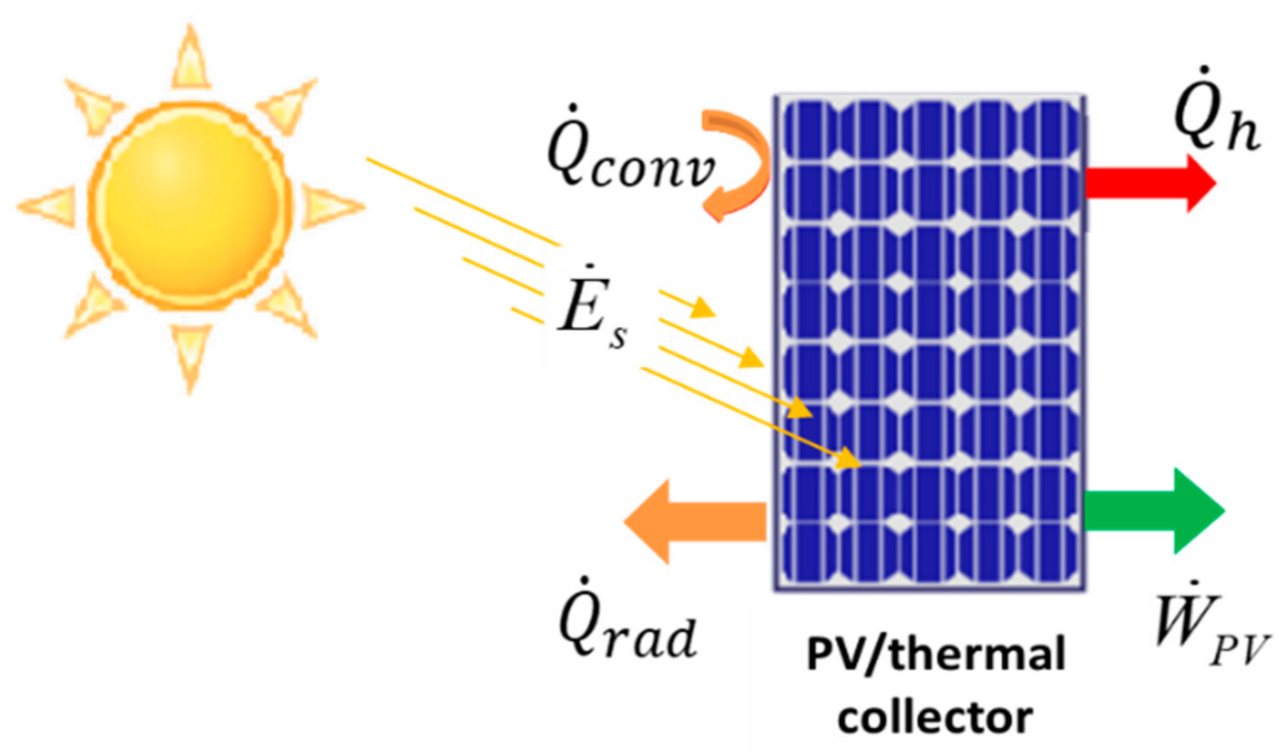
The different types of energy flows that are involved in a PV/thermal collector (PV/TC) system, according to the operating conditions applied to the panel in
Figure 2, are considered.
Assuming that the PV/TC panel temperature is homogeneous, and the back and lateral and side surfaces of the panel are adiabatic, only the exchanges of the front surface with the external environment are considered (convective with the ambient and radiative with the sky). Applying the first law of the thermodynamics on PV/TC association, which is considered as a single uniform control volume and in steady-state operation, gives the following:
where
is the absorbed solar incoming irradiation,
is the electrical power production,
is the thermal power production, and
are the convective and radiative heat losses, respectively.
The total solar energy that is absorbed by the PV panel is as follows:
where
is the solar absorptance of PV layers,
is the solar transmittance of the glazing, and
is the global incident irradiation.
The electricity energy produced by the cell is expressed by Equation (3) [
25]:
In which
is the electrical efficiency depending on the actual operating cell temperature and
is the reference electrical efficiency of the PV module operating at the standard test conditions (STC)
TSTC = 25 °C under a global solar irradiation
IG = 1000 W·m
−2 [
25]. The temperature coefficient
is based on the material properties, and
Tcell is the operating cell temperature. The values of
and
used for this study are from standard commercial PV panels.
To determine the heat exchange between the panel and the ambient air, a coefficient of global convective (natural and forced) heat transfer is considered. Test et al. experimentally evaluated the convective exchange coefficient of a plate placed in the natural environment and the wind speed at a height of 1 m above the plate was recorded. They were able to develop a linear correlation that is used here [
26]:
The convective heat coefficient transfers
depends on the wind velocity V
w as follows:
The rate of radiative heat exchange is given by the Stephan-Boltzman law [
27]:
where
is the emissivity of the PV panel and
is the Stephan–Boltzmann constant. The temperature of the sky
Tsky depends on the ambient temperature
Tamb and is expressed as follows:
.
The energy analysis can be carried by considering the following performance criteria:
2.1.2. Exergetic Analysis of the PV/Thermal Collector System
The exergy analysis allows us to evaluate the quality of energy involved in a system and to standardize the evaluation of the thermodynamic quality of systems in which different forms of energy are involved. The exergy quantifies the maximum work that can be ideally produced by an ideal reversible process, such as a Carnot engine, and can thus be defined as the work content of the energy. The electrical energy is a high-quality energy and is thus considered as pure exergy as it can be ideally fully converted into work using an ideal electrical motor. The thermal exergy (characterizing the quality of the thermal energy) depends on its temperature (
Th) relative to the reference temperature (
T0), for which the exergy content of the thermal energy is zero (dead state). The thermal exergy corresponds to the maximum amount of work that can be ideally produced by a Carnot cycle consuming the heat
at
Th and releasing heat at
T0:
The Carnot factor is introduced to estimate the exergy content of a given amount of thermal energy available at a temperature Th. In that study, the reference temperature T0 is equal to Tamb.
To evaluate the transformable equivalent work and estimate the exergy destroyed in the PV/TC panel, and hence its thermodynamic quality, an exergy balance of the system can also be expressed as:
Several methods are proposed in the literature [
28] to determine the solar exergy
Exs of the incoming irradiation. One of the most commonly used calculation methods is proposed by Chow [
14] considering a temperature
Ts of the sun of 6000 K:
Additionally, the exergy of heat
recovered at the operating temperature
Tcell of the panel is expressed as follows:
Since electrical energy can be ideally converted entirely into work, by definition, the exergy of the electricity production is the electrical energy rate .
From these definitions, the electrical exergy efficiency, thermal exergy efficiency, and overall exergy of a PV/TC system can be calculated from the following relations:
2.2. Thermally Driven Systems Coupled to the PV/Thermal Collector Panel for Heat Valorization
In this part, an analysis of different energy conversion systems coupled to a PV/TC system for the valorization of the produced heat is carried out. Indeed, the heat can be valorized in work by using a di-thermal engine cycle, or in cold by using a tri-thermal machine. Such a coupling will allow us to reduce the PV panel operating temperature, thus improving its electrical performances, and produce work or cold that will increase the overall performances of the system. The output energies of each coupling are analyzed and evaluated for each configuration to determine the optimal operating conditions according to the desired application.
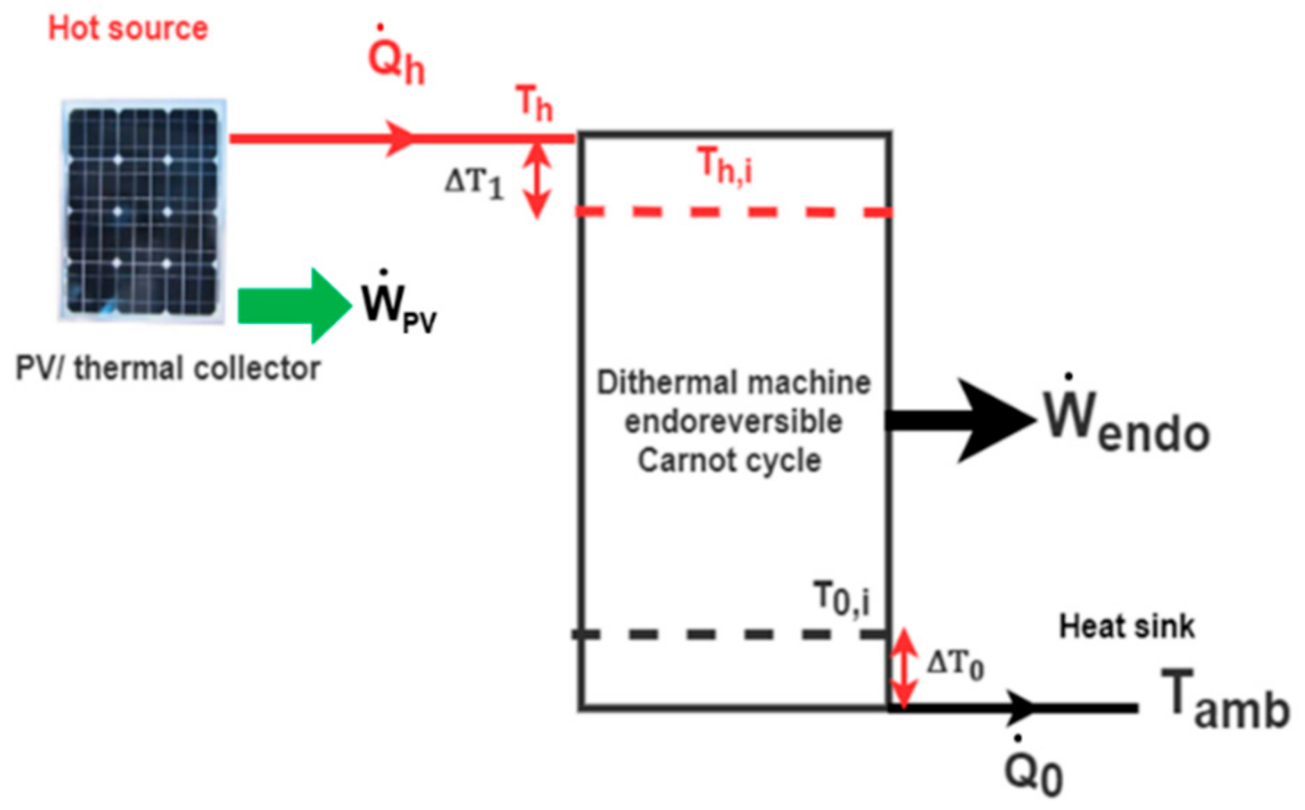
2.2.1. PV/Thermal Collector System Coupled to a Di-Thermal Endoreversible Carnot Engine for Additional Work Production
The first combination consists in coupling the PV/TC system with a di-thermal machine exploiting the heat produced by the PV/TC, in order to produce a useful work that can be later converted in additional electricity, as depicted in
Figure 3.
The considered di-thermal machine is an endoreversible Carnot engine [
29]. This conceptual machine enables a more realistic analysis in comparison to the Carnot machine one. It takes into account the thermodynamic irreversibilities caused by the heat transferred between the cycle and the heat sources and sinks. The cycle then operates in a reversible way between internal temperatures (
Th,i) and (
T0,i), with no internal thermodynamic irreversibility. Therefore, the work
that can be produced by the consumption of a given amount of thermal power
at
Th can be estimated by considering the thermal pinches required for the heat exchange as:
With a work engine efficiency cycle defined as follows [
29]:
The temperature differences Δ
T that are required for heat exchange between the external sources with the endoreversible Carnot engine are estimated under given realistic heat exchange coefficients by the following equations.
where (
US)
0 and (
US)
h are the global heat conductance between the endoreversible Carnot engine with the ambient and the PV/TC, respectively.
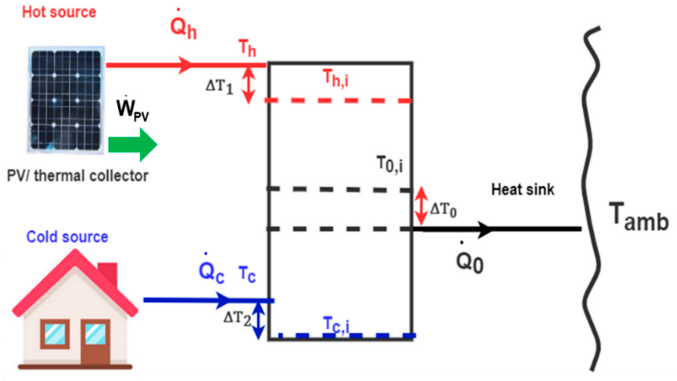
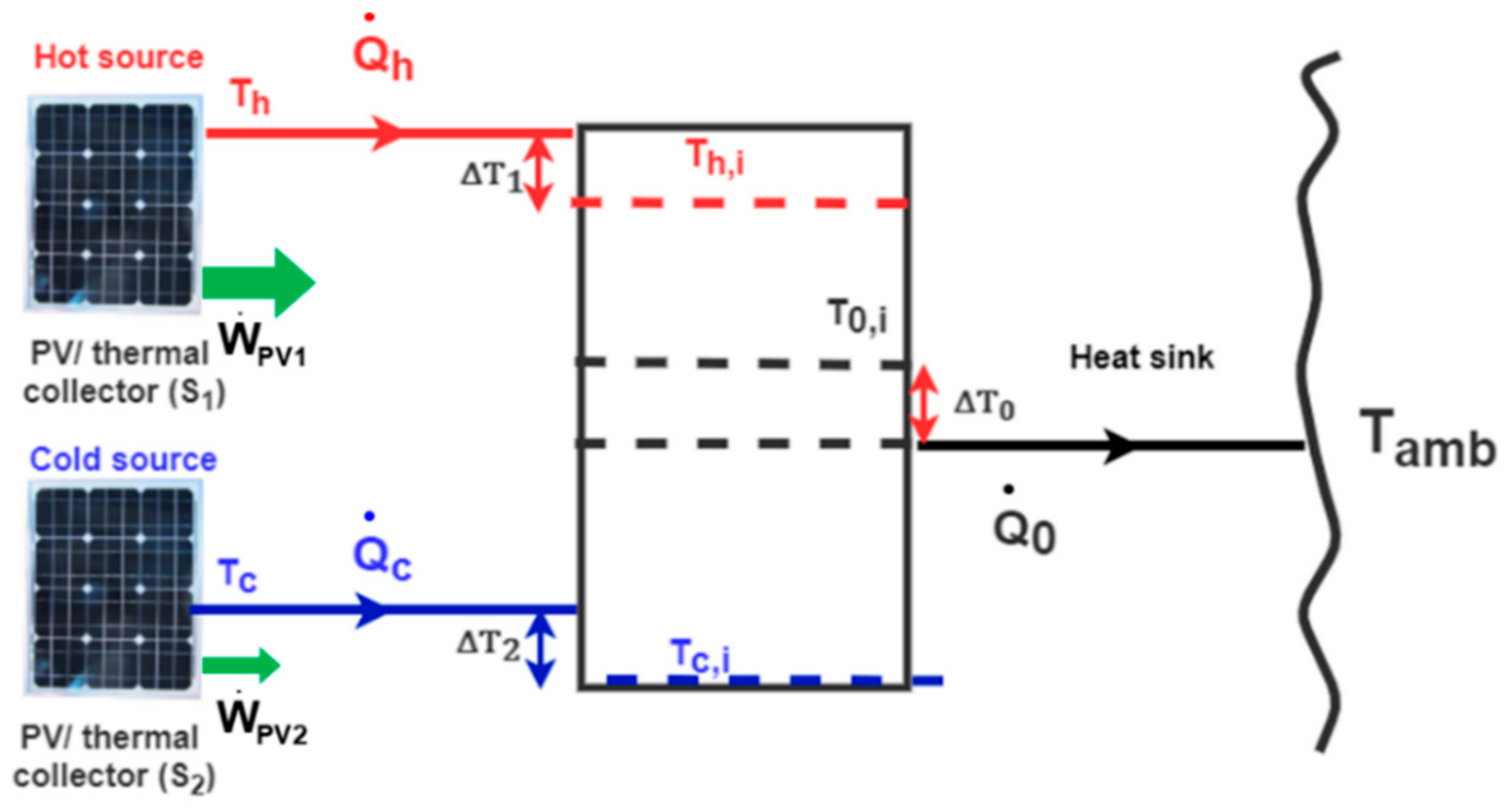
2.2.2. PV/Thermal Collector System Coupled to a Tri-Thermal Machine for Cold Production
The second combination consists in coupling the PV/TC system with a tri-thermal machine in order to valorize the heat produced into cold as presented in
Figure 4. A tri-thermal system is a closed thermodynamic system that exchanges only thermal energy with the external thermal sources/sinks. It operates between three different temperature levels: a hot source temperature noted
Th, a cold source temperature noted
Tc, and a heat sink temperature
Tamb that generally corresponds to the ambient environment.
and
are the heat quantities exchanged between the system and the external thermal sources at
Th and
Tc, respectively.
From a thermodynamic point of view, the tri-thermal system can be considered as the result of the coupling of two di-thermal cycles: an engine cycle and a reverse refrigeration cycle. Therefore, this tri-thermal system can be analyzed as an endoreversible machine consisting in the coupling of two endoreversible di-thermal cycles: an endoreversible engine cycle operating between
Th and
Tamb coupled to an endoreversible refrigeration cycle operating between
Tc and
Tamb. The overall performance of the endoreversible tri-thermal machine can thus be realistically characterized by considering the thermodynamic irreversibilities due only to the external heat exchange as follows [
30]:
With the endoreversible engine cycle efficiency defined by the Equation (16).
The produced work by the first cycle is internally consumed by the second reverse cycle to produce cold (
) at
Tc, releasing heat (
) also at
Tamb. This performance of this refrigeration cycle can also be characterized through its endoreversible coefficient of performance defined as:
where the temperature differences Δ
T2 and Δ
T0 that are required for heat exchange between the external sources with the refrigeration cycle are estimated by using Equations (17) and (18) in the same conditions, respectively.
By replacing Equations (16) and (20) in Equation (19), it gives the following [
30]:
The cold produced by such a tri-thermal machine can be used in several ways. It can be used for air conditioning of a building, or to meet a specific demand, such as the cooling of electronic devices like inverters. The final energy outputs of such a system are thus electricity and cold, which has to be optimized depending on the targeted application.
2.2.3. Active Cooling of an Additional PV Panel by an Endoreversible Tri-Thermal Machine
Another application of the cold produced by the tri-thermal machine is to provide an active cooling of an additional PV panel area to improve the overall electrical production. The impact of the active cooling PV panel by the endoreversible tri-thermal machine is therefore investigated here. As shown in
Figure 5, the first panel (hot source) is maintained at a first operating temperature
Th, while the second panel is cooled and maintained at a second operating temperature
Tc (cold source) by the endoreversible tri-thermal machine. As the amount of cold produced
is fixed by these operating temperatures, then a given surface
S2 of the second PV panel can be maintained at that temperature
Tc.The working conditions of the second panel at this temperature allow for a better electrical efficiency as it is maintained at a temperature lower than the ambient one or at least at the ambient temperature. Thus, for this coupling configuration, the only energy output of the system is the electrical work. The performance of both PV panels must be optimized so as to reach the maximum global electrical performance. The thermal energy at
Th produced by a surface
S1 of the first PV panel is used as the driving heat source of the tri-thermal machine. The cold produced at temperature
Tc maintains the second PV panel surface
S2 at this temperature. Thus, depending on the cold temperature
Tc, the surface
S2 is determined by the following set of relations characterizing the cooling performances of the system coupling the two PV panels with the endoreversible machine:
where Equation (23) can be developed and written as Equation (21).
The electricity produced by these two panels of surface
S1 and
S2 is then compared to the production of the same surface of purely PV panel (
S1 +
S2) under the same conditions, but without being cooled or recovering heat (i.e., operating at stagnation temperature
Tst). The overall electrical gain is defined as:
This overall electrical gain can be compared to the electrical gain obtained for each PV panel that can also be defined as:
3. Results and Discussion
The results of the analyses described in this section are performed considering the actual characteristics of the PV panels manufactured by SUNPOWER (SPR-Max2-360-COM) and resumed in
Table 1. The study is performed considering an ambient temperature of 40 °C, a wind speed of 1 m·s
−1, and several solar irradiations from 400 to 1000 W·m
−2. A simulation tool was developed in the Python environment to solve the equations of the thermodynamic model presented in the previous section.
3.1. Energy and Exergy Analysis of a PV/TC Panel Alone
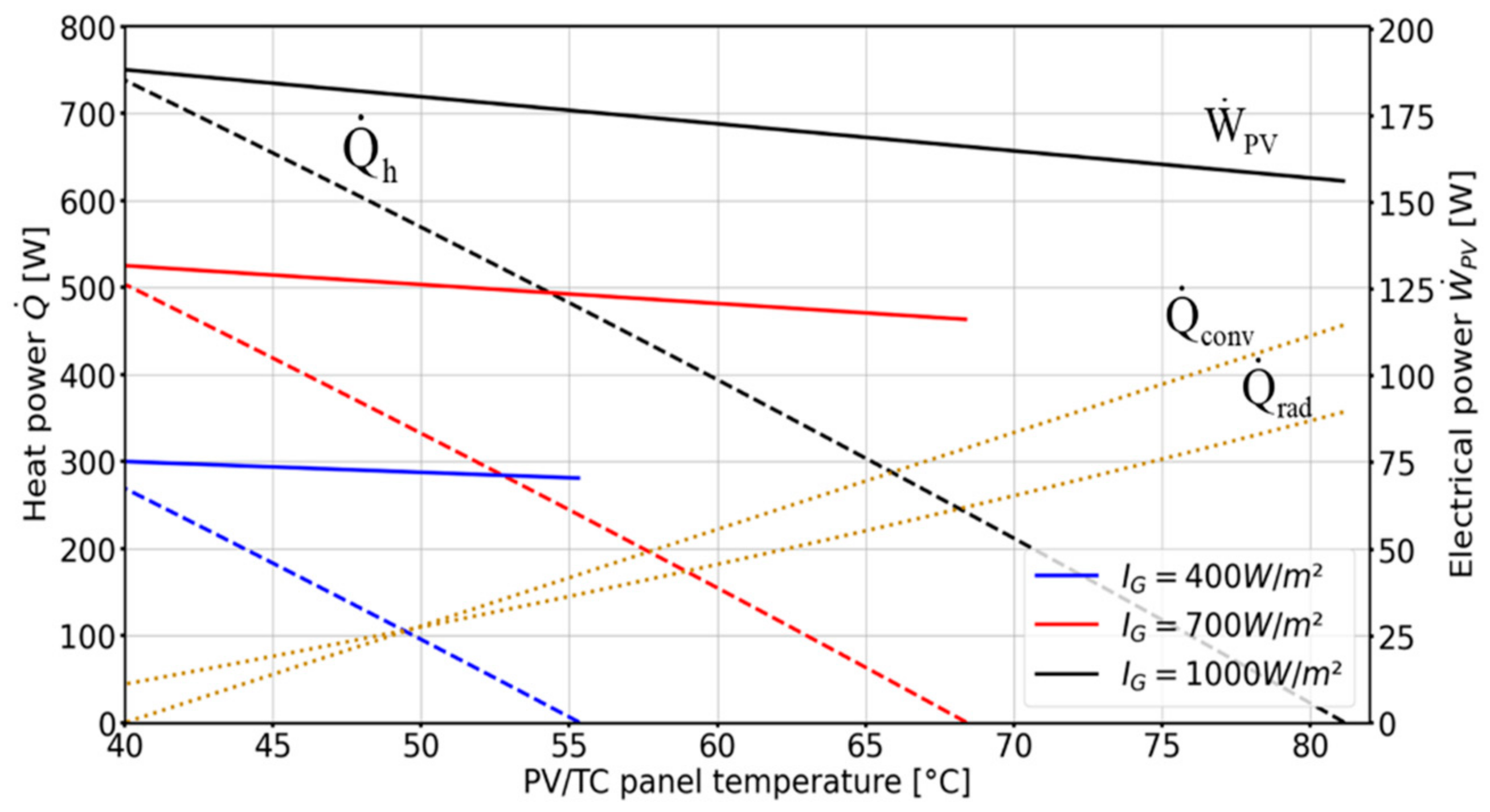
Figure 6 shows the evolution of electrical and thermal powers generated by 1 m
2 of the chosen PV panel, as function of the operating temperature of the PV panel for different solar irradiations from 400 to 1000 W·m
−2. The PV panel temperature evolves from a maximum (or stagnation) temperature T
st varying from 81 °C to 40 °C. For this equilibrium temperature at a given solar irradiation, the electrical production is the lowest and no heat recovery is possible: all the generated heat is lost to the ambient environment. When heat is extracted from the PV panel, the temperature of the panel decreases, which increases the electrical energy produced and the thermal energy that can be recovered. This evolution is quasi-linear (even if the radiation losses evolution is not linear with the sky) for the global energy of the system. As expected, the best performances are achieved when the panel operating temperature is equal to the ambient one.
Regarding the thermal energy generated from the PV/TC, if no heat is recovered when operating under a solar irradiation of 1000 W·m−2, the panel will reach the thermal equilibrium with a maximal achievable temperature corresponding to an electrical production of 156 W·m−2 and 0 W·m−2 of thermal energy. The low temperature of the PV/TC panel allows us to reduce energy losses to reach, at ambient temperature, a maximum electricity production of 188 W·m−2, a maximum thermal energy production of 738 W·m−2, and the convective heat losses to the environment that are null. The working temperature of the PV panel has a great importance; it has an impact on the utility of the recovered heat, as it can be seen in the exergy analysis that is carried out hereafter.
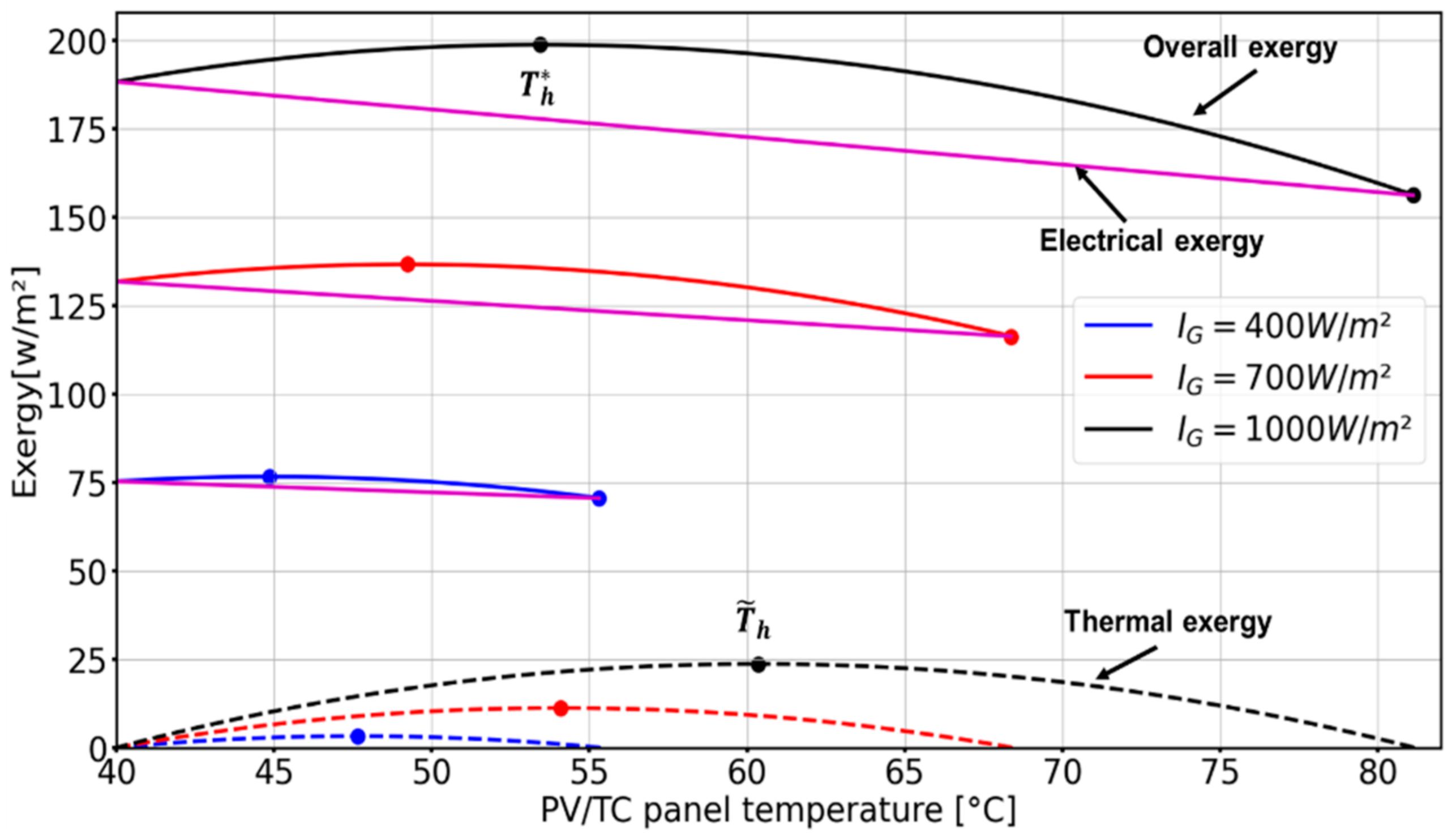
Figure 7 shows the evolution of the thermal, electrical, and overall exergy of the PV/TC panel operating under the same operating conditions as defined previously in the energy analysis. Contrarily to the linear evolution of the different forms of energy, only the electrical exergy evolves in a linear way with the cooling of the panel due to its definition as equivalent to the electrical energy. The thermal exergy increases from 0 W·m
2 when the PV/TC is at the stagnation temperature
Tst to reach a maximum value of 25 W·m
−2 for a solar radiation of 1000 W·m
−2 and then decreases with the decrease of the PV panel temperature to again reach a null value when the PV panel operates at ambient temperature. As it can be noticed in
Figure 7, for each solar irradiation, two optimum operating temperatures
and
can be defined as follows: the first one corresponds to the temperature that maximizes the overall exergy content, and the second one corresponds to the temperature that maximizes the thermal exergy content. The maximum exergy content of the thermal energy for solar radiation of 1000 W·m
−2 is obtained when the PV panel operates at 62 °C, which corresponds from
Figure 6 to a heat production of around 380 W·m
−2 and an electrical production of 170 W·m
−2. Despite the high amount of heat recovered at the ambient temperature, the thermal exergy is null because the dead state (thermal equilibrium with the environment) is reached, as we can see in Equation (11). Regarding the evolution of the global exergy of the PV/TC, it increases as the PV panels cool. After the temperature of 62 °C for which the thermal exergy is maximum, the overall exergy continues to increase even though the thermal exergy degrades because the electrical exergy increases and compensates for this degradation. The overall exergy then reaches a maximum of 200 W·m
−2 for a PV operating temperature of 54 °C and slightly decreases to equal the electrical exergy obtained by the PV panel when operating at an ambient temperature. It can be noticed that the thermal exergy is much lower than the electrical exergy because of the low operating temperature of the collector.
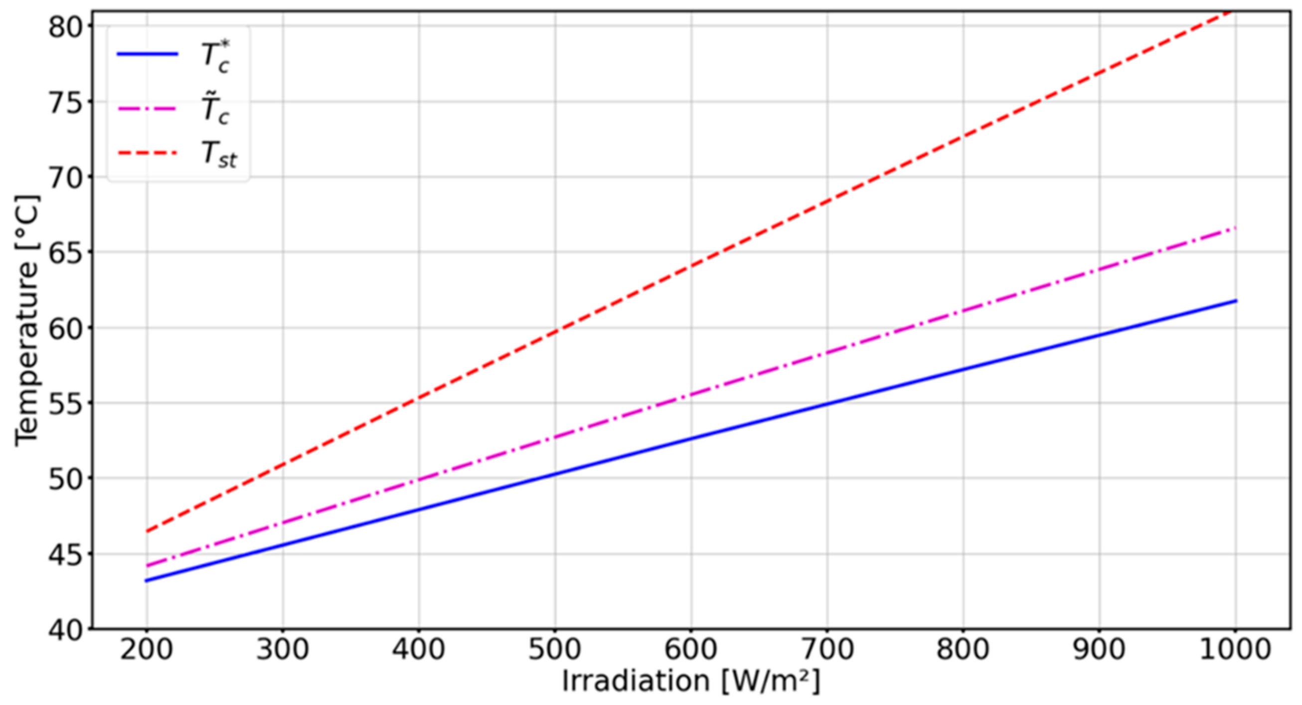
The exergy amounts produced by the PV/TC panels depend on the incoming solar irradiation. When the solar irradiation decreases, the stagnation temperature also decreases as well as the optimal temperatures that maximize the thermal and overall produced exergy. These optimal temperatures decrease almost linearly with decreasing solar irradiation as presented in
Figure 8. The stagnation temperature varies between 81 °C and 46 °C with the variation of solar irradiation from 1000 W·m
−2 to 200 W·m
−2. These values are similar to those obtained in the study carried out by Jakhrani et al. [
31], who proposed several experimentally validated correlations for the evaluation of the stagnation temperature of a PV panel for various solar irradiations. Although the operating ambient conditions are not exactly identical, it can be noticed that the results presented in this work are close to those obtained by Jakhrani et al.
3.2. Performance Analysis of the Coupling of a PV/TC Panel with an Endoreversible Carnot Engine
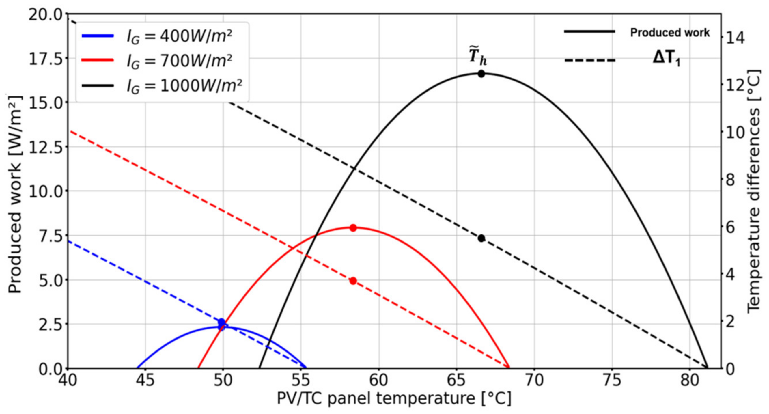
Figure 9 presents the work that can be produced by an endoreversible engine cycle driven by a PV/thermal collector delivering heat at
Th. The temperature differences Δ
T0 and Δ
T1 are calculated using Equations (17) and (18) taking the values of global heat conductance as (US)
0 = 300 W·K
−1 and (US)
h = 50 W·K
−1. These values are taken for a realistic heat exchange coefficient where (US)
0 is considered larger than (US)
h, and therefore Δ
T0 is smaller than Δ
T1. One can see in
Figure 9 that the produced work increases from zero to a maximum value and decreases after up to zero when the PV panel temperature decreases, while the temperature difference required for the heat exchange Δ
T1 between the PV panel and the engine cycle increases linearly. For a solar irradiation of 1000 W·m
−2, an optimum operating Δ
T1 for the heat exchange of about 5.5 °C enables to produce a maximum work of 16.5 W·m
−2, corresponding to an optimum operating temperature of
= 68 °C for the PV panel. Note that the endoreversible engine cycle considered in this study is a simplified model of any engine. A similar approach has been considered by Fudholi et al., who experimentally studied the coupling between a PVT panels and a TEG module, which is a thermoelectric di-thermal generator [
22]. For a solar irradiation of 1000 W·m
−2, the additional electricity production by the TEG module is about 12 W, which is of the same order of magnitude as the production of the endoreversible di-thermal engine considered here.
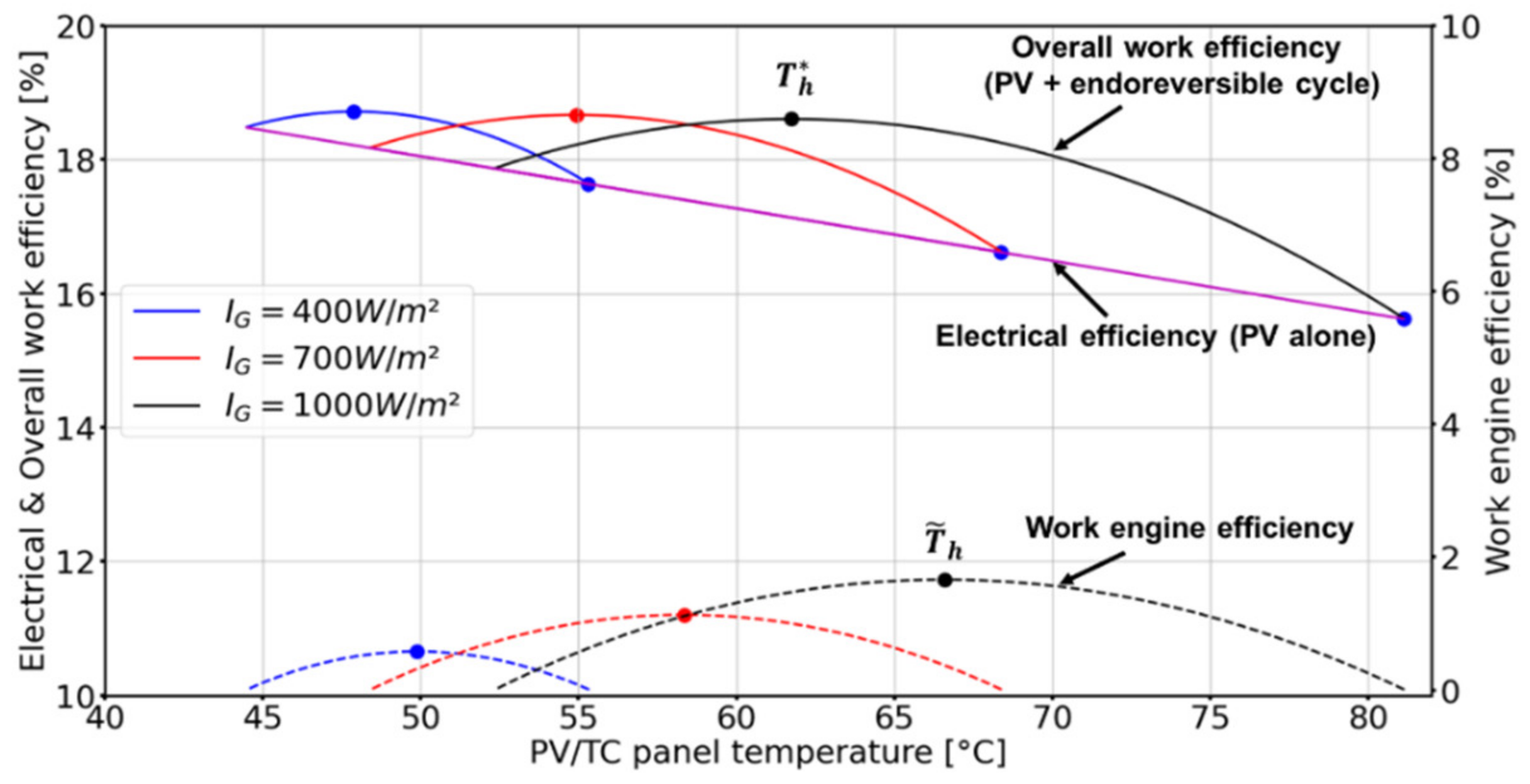
By considering the electricity and work production, the corresponding exergy efficiency of the global system is assessed and represented in
Figure 10. For the electrical exergy efficiency, the evolution is similar to the electrical power evolution (
Figure 6) as electrical energy is considered as full exergy: it starts at 15.5% for the maximum operating temperature of the PV panel of 81 °C (stagnation temperature under a solar irradiation of 1000 W·m
−2) and increases slightly as the PV panel is cooled down. The thermal exergy efficiency follows the same evolution as the work produced by the endoreversible engine: it starts at 0 for the PV panel’s stagnation temperature, reaches a maximum value of 1.67% at
, and decreases to zero as the PV panel’s temperature decreases. As a result, the global exergy efficiency increases when the PV panel’s temperature decreases, thanks firstly to the improvement of the electricity production and secondly to the valorization of the increasing amount of heat recovered from the PV panel by the endoreversible engine. This endoreversible cycle exploits this recovered heat produced to convert it into additional work: it reaches a maximum overall efficiency of about 18.7% for an optimal operating temperature of
= 62 °C under 1000 W·m
−2 of solar irradiation. However, when the temperature of the PV panel decreases below this optimal operating temperature
, even if the electrical production increases slightly, the overall exergy efficiency decreases because of a significant decreasing of the work produced by the endoreversible engine.
Finally, by exploiting the thermal energy recovered from the PV panel to produce additional work through an endoreversible Carnot machine, it should be possible to achieve higher overall performances by further converting the produced work into additional electricity. The overall electrical performance obtained by such coupling should be close and higher than to those obtained by a conventional PV panel operating at ambient temperature, whatever the solar irradiation. The electricity produced by this PV panel operating at STC conditions (ambient conditions at 25 °C under 1000 W·m−2) is about 188 W·m−2, while the overall exergy achieved by this PV panel operating at = 62 °C coupled to the endoreversible engine is about 186 W·m−2.
3.3. Performance Analysis of the Coupling of a PV/TC Panel with a Tri-Thermal Endoreversible Machine for Cold Production
For each amount of thermal energy recovered from the PV panel at a temperature
Th, a resulting amount of cold is produced, which also depends on the desired cold temperature
Tc. It can be seen from Equation (21) that the lower the temperature reached in the cold production, the less is the quantity of produced cold.
Figure 11 represents the evolution of the produced cold by such a tri-thermal machine as a function of the desired cold temperature when coupled to 1 m
2 of panel delivering heat
at the previously defined optimal operating PV panel temperatures,
and
.
The produced cold corresponds to that delivered in the optimum operating conditions of a hot PV panel that maximizes either its overall exergy (
) or just its thermal exergy (
), as seen previously in
Figure 10. For 288 W·m
−2 of thermal energy delivered by the PV panel at
= 68 °C (
Figure 6), 143 W·m
−2 of cold at 20 °C can be produced under a solar irradiation of 1000 W·m
−2, while only 128 W·m
−2 of cold can be produced at 20 °C when the PV panel operates at the optimum temperature
= 62 °C, which maximizes the overall exergy production of the panel with 380 W·m
−2 of recovered thermal energy. As seen previously in the coupled PV/TC system to a di-thermal endoreversible Carnot engine in
Section 2.2.1, the amount of cold produced by the tri-thermal machine obtained at the temperature
corresponding to the maximum thermal exergy production by the PV panel is more important than the cold produced at
. Moreover, for a cold production at 20 °C, the coefficient of performance of the endoreversible tri-thermal machine is about 0.24 when operated with heat provided at
= 68 °C, while it is 0.21 when operated at
= 62 °C. The cooling performances of these tri-thermal endoreversible machines that are considered in this study are closed and similar to those obtained by the silica gel/water adsorption cycle operating in the same temperature range [
32].
3.4. Electrical Performance Enhancement Provided by an Active Cooling of Additional PV Panel by the Endoreversible Tri-Thermal Machine
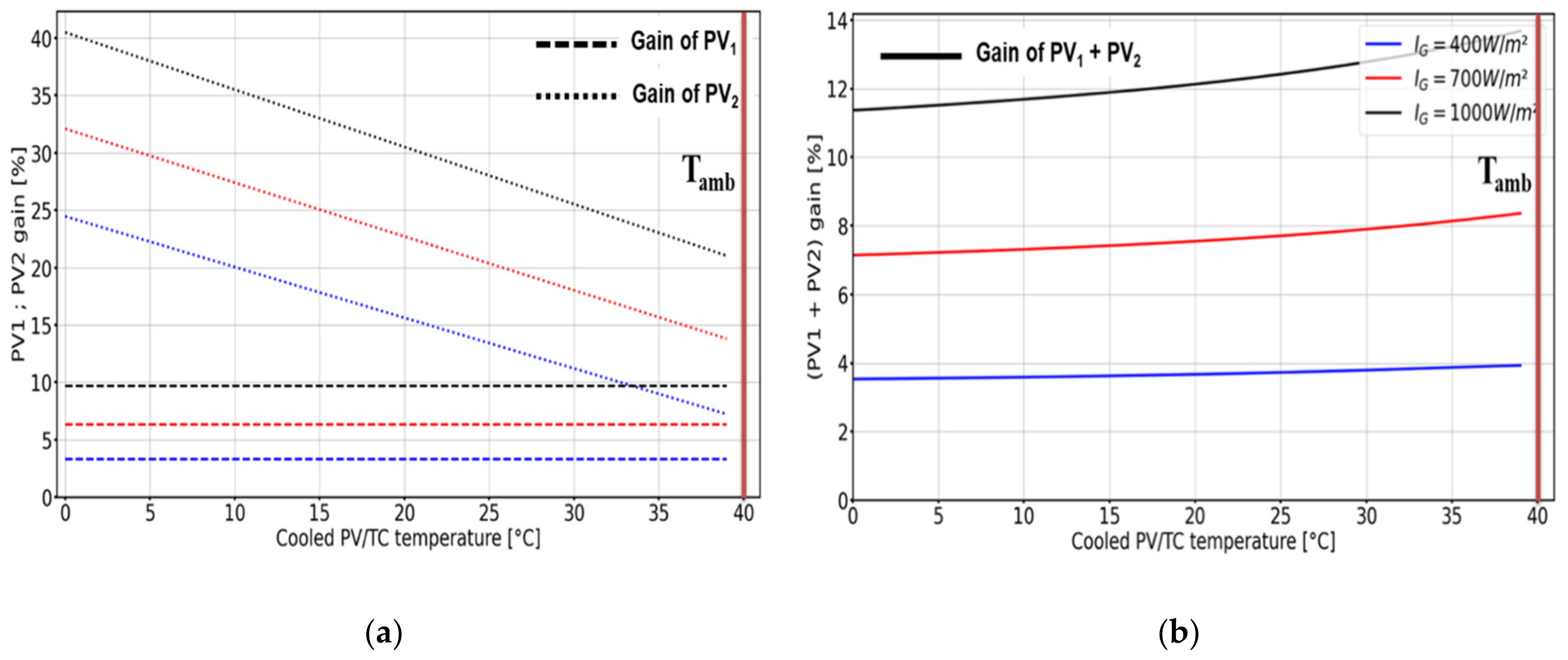
The evolution of these electrical gains is represented in the
Figure 12 as a function of the cooled PV temperature, as well for different solar irradiations.
Figure 12 shows that the gain of the first PV
1 panel working at the optimal global exergy temperature
is not impacted by the operating temperature of the second PV
2 panel
Tc. Its gain is constant as its operating temperature is kept fixed and depends only on the solar irradiation: the gain is about 9.84% for a solar irradiation of 1000 W·m
−2 and an ambient temperature of 40 °C. For the second panel that is actively cooled below the ambient temperature, it can be noticed that the lower the temperature is, the more important the gain is with a linear evolution that can reach 40% of gain for these operating conditions.
The overall electricity production gain increases slightly when the operating temperature Tc of the cooled panel is close to the ambient temperature, because in such a temperature range, the amount of cold produced by the tri-thermal machine increases from 80 W·m−2 to 430 W·m−2 and allows us to maintain a larger surface S2 at Tc. The electrical production of the second panel becomes more substantial and makes the overall gain increase to reach 12.81% when the second PV panel is at temperature Tc = 30 °C.
3.5. Comparison with Conventional Cooling System by Heat Dissipation
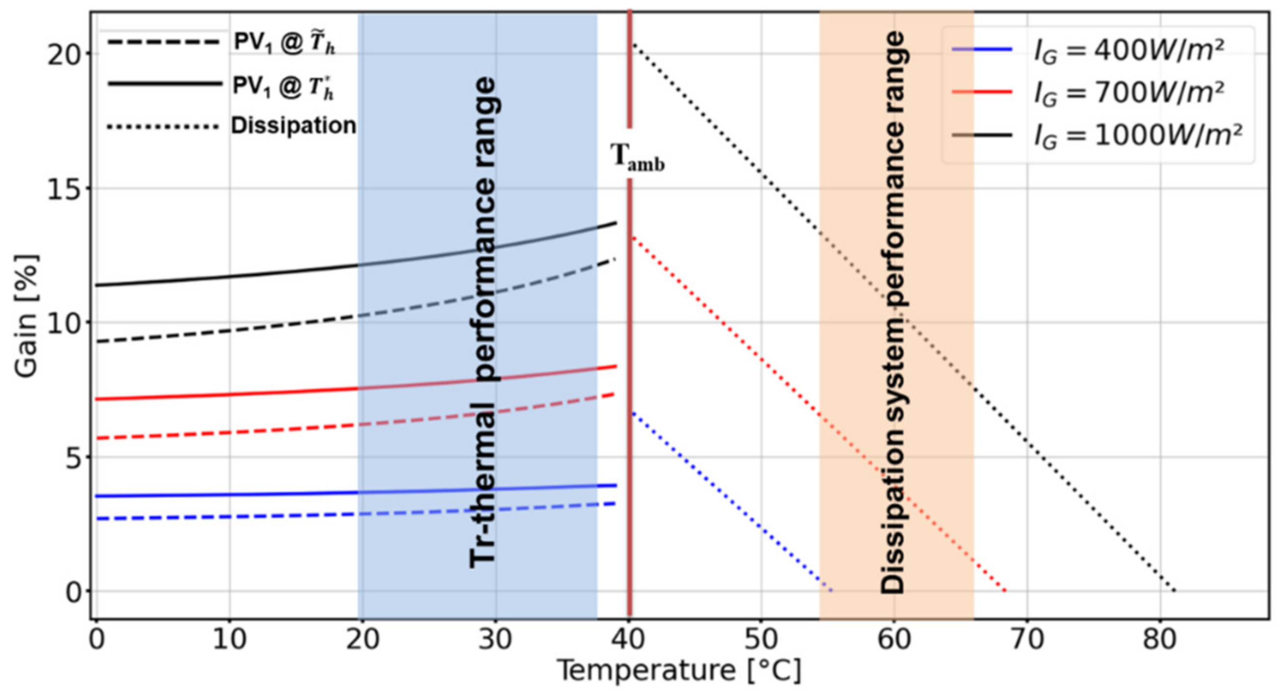
Figure 13 shows a comparison of the performances of this active cooling of PV panels performed by a tri-thermal machine with a simple heat dissipation system of PV panels to ambient temperature, such as a water-cooled heat exchanger or a phase change material placed on the back side of the PV panel. Such a heat dissipation system conventionally enables the PV panels to operate generally from 15 to 25 °C above the ambient temperature.
When operating with an endoreversible tri-thermal refrigeration machine, the overall electrical performance is a bit higher than the one obtained by a heat dissipation device, such as a heat exchanger on the back side of the PV panel. Heat dissipation systems keep PV panels at least at
Tamb + 15 °C, with water forced convection or phase change materials. To make a fair comparison between the tri-thermal active cooling with the heat dissipation systems, a reference case in terms of operating conditions is considered at this temperature of
Tamb + 15 °C, where the two systems meet the same performance. One can notice that the tri-thermal machine allows for more flexibility in terms of gains achieved in comparison with the heat dissipation system. For these operating conditions, for the same surface of panel, the electrical gain achieved by the heat dissipation system keeping the PV panel at a temperature (
Tamb + 15 °C) is equal to or lower than the gain obtained when the tri-thermal machine operates at
, whatever the temperature
Tc of the cold produced. Unlike the heat dissipation system, to ensure this gain, the operating parameters of the panels temperature must be set at
Th =
Tamb + 12/15 °C or lower. Finally, it can be noticed in
Figure 13 that the gains obtained in the
operating conditions are higher than the gains obtained in the
operating conditions. This is because, even though the amount of cooling is higher at
operating conditions and maintains a larger
S2 area of PV
2 at
Tc, operating conditions at
have a higher gain than
for the same
S1 area.
4. Conclusions
The objective of this study was to investigate the potential operating conditions to improve the overall efficiency of a PV panel induced by the recovery of the thermal energy produced by the latter and its possible valorization into work or cold.
A thermodynamic analysis of the coupling of PV panels with an endoreversible Carnot engine was presented and showed that there are two optimal panel operating temperatures and , respectively, which allow us to maximize the thermal exergy produced by the PV panel, and thus its potential to be valorized into work (or electricity) or to maximize the overall thermal and electrical exergy of the PV panel.
The analysis of the valorization of the recovered heat into cold by an endoreversible tri-thermal machine showed that the amount of cold produced is higher if the PV panel operates at temperature than at . This difference is related to the higher thermal exergy content available at than . As a result, the coefficient of performance of this endoreversible tri-thermal machine is 0.24 when using PV heat at and 0.21 for operating conditions.
In the case of an active cooling of an additional PV panel surface, the electrical gains obtained for these two optimum temperatures of operation increase jointly when the produced cold temperature is close to the ambient temperature. However, operation at the optimum temperature ensures a more stable gain when the operating temperature of the second cooled panel varies, with a slightly larger gain for the low temperatures of the cooled panel of about 12.8% in comparison with the working conditions at of about 11.1% at Tc = 30 °C and 1000 W·m−2.
By comparing the performances of the active cooling system with conventional heat dissipative systems identified as state of the art, it is found that the endoreversible tri-thermal machine enables us to reach similar performances when the cooled PV temperature Tc is at 20 °C, as dissipative systems enable the PV panel to work at Tamb + 15 °C. Accordingly, this active cooling solution can be considered as technically competitive with the heat dissipative systems based on forced water convection or heat pipe.
Coupling such a tri-thermal machine with PV panels could be relevant to prevent the deterioration of the PV panel over time, thanks to a lower average operating temperature. The conclusions of this theoretical study must be confirmed by a transient behavior analysis of the PV/Thermal collector panel and an experimental approach.


