A Coordinated Voltage and Reactive Power Control Architecture for Large PV Power Plants


Department of Engineering and Architecture, University of Trieste, 34127 Trieste, Italy
*
Author to whom correspondence should be addressed.
Energies 2020, 13(10), 2441; https://doi.org/10.3390/en13102441
Submission received: 11 April 2020
/
Revised: 7 May 2020
/
Accepted: 9 May 2020
/
Published: 13 May 2020
(This article belongs to the Special Issue Grid-Connected PV Plants)
Abstract
:The increasing presence of nonprogrammable renewable energy sources (RES) forces towards the development of new methods for voltage control. In the case of centralized generation, the hierarchical regulation or secondary voltage regulation (SVR) is guaranteed by coordinated voltage and reactive power controls in transmission systems. This type of regulation loses effectiveness when the generation becomes distributed and based on small and medium sized generators. To overcome this problem, it is important that also distributed generators, typically based on RES, participate in the voltage regulation. By starting from the methodologies already applied, this work wants to present a new method for involving distributed generators in SVR. The novelty is given by the application of an existing methodology to the new configuration of electrical grids characterized by a relevant distributed generation. The aim is to control the distributed generators (DGs) as coordinated sources of reactive power for conveniently supporting the voltage regulation. In this paper, a real large photovoltaic (PV) plant is considered. The power plant is composed of several PV generators connected through a distribution network. With the algorithm proposed, the set of generators can be treated as a single traditional power plant that can participate in the hierarchical voltage regulation. The reactive power of each single generator is coordinated in a way similar to the SVR used in several national systems.
1. Introduction
As well known in electrical engineering, user appliances work in the best conditions (i.e., performance, efficiency, and lifetime) when fed at a rated voltage or within a small voltage deviation from that value [1]. Not only the loads’ section but similar considerations can also be drawn for production, transmission, and distribution systems (e.g., generators, transformers, lines, reactors, and shunt capacitors). Indeed, also in these cases, the voltage on components is to be maintained within a limited range for avoiding various negative effects on the system operation [2,3].
During a standard operative scenario in transmission grids, undesired voltage fluctuations at the grid nodes are mainly caused by variations in absorbed power, which is variously requested from the different loads connected to the network [4]. On the other hand, temporary out of service of any network component (lines, transformers, etc.) are responsible for significant variations in supplied voltage and even the loads’ disconnection [4]. For the reasons expressed so far, the transmission system operator (TSO) must guarantee an adequate voltage control service, i.e., a complex of measures for achieving a suitable voltage control in the different network nodes [4]. Clearly, each TSO operating on a specific grid can implement a peculiar voltage control service, which is definitely not stiffly established. Being the high voltage (HV) nodes mainly influenced by the flows of reactive power [4], the voltage control is typically performed by regulating the reactive power flows by means of different reactive power resources. For giving some examples, it possible to mention FACT devices, synchronous generators, synchronous condenser, transformer tap changers, static VAR compensators, capacitor banks, and capacitance of lines and cables [5].
During the last decades, several countries have implemented hierarchical voltage control systems, practically based on the reactive power provided by conventional large power plants [6]. In this regard, a review of the adopted systems is reported in [5]. As a matter of fact, the standard voltage control systems have been designed and developed for traditional electric power grids, which are characterized by a unidirectional energy flow (from large production centers up to the loads). Nowadays, this assumption is not valid anymore, where the electric power systems are experimenting a great structural change by moving from the centralized production paradigm to the distributed generation model [7,8]. The latter is characterized by small–medium size generation centers, typically based on renewable energy sources (RES), which are conveniently (sometime randomly) distributed throughout the territory. The large penetration of RES leads relevant consequences on several aspects (power quality, power losses, and voltage profiles), as discussed in [9,10,11].
The RES scenario in EU-28 is constantly evolving [12]. Just to give some data [12], at the end of 2014, the installed RES power has been equal to 369,511 GW, more than a third of total installed power (37.8%). In detail, RES power plants are capable of contributing to the production of 930 TWh, another time almost one-third of the total production (29.2%). This data can be summarized not only in the significant growth rate of RES in the last years but also in the fact that RES growth is the only one having a positive index among the different resources. There are several technologies that contribute to renewable generation: among others, hydroelectric, wind, biomass, and photovoltaic [12,13,14]. Particularly, the last references provide some important reports for the context frame.
Nowadays, the secondary voltage regulation (SVR) for HV networks is based on traditional fossil power plants and large hydroelectric power plants, while most of the new renewable energy plants are not taking part in this task [5]. By considering this aspect, the existing voltage control systems are experiencing a decrease in the control capability, especially when the power of conventional thermal plants is replaced by the one produced by distributed generators (DGs) [5]. For what concerns the connection, medium voltage (MV) and low voltage (LV) distribution networks are the standard end-point for RES power plants, whilst the HV transmission system represents the future connecting point for high-power renewable sources. In this regard, the Italian case represents an interesting example, where 6.4% of PV plants are directly connected to the HV grid by the end of 2014 [15]. The Italian case is noteworthy also for the high presence of nonprogrammable RES power plants, whereas the Italian TSO implements a hierarchical voltage control by adopting the production plants as actuators [5].
Independently from the voltage level of interconnection, the introduction of RES technology can determine important consequences on the voltage control [16]. The RES operation outside the constant unitary power factor is commonly accepted as a standard requirement, independently from the interconnection at transmission or distribution level [17,18,19,20]. Particularly, last references are aimed at defining regulations and guidelines for network code.
In this regard, the authors have largely studied the contribution of photovoltaic (PV) plants in supporting the network voltage: in [21], the voltage control functionality is guaranteed by modulating the reactive power and bounding the injected ramp of active power, while PV power plants are regulated for behaving as STATCOM devices in [22]. As proposed in [23], PV units can provide reactive power compensation as ancillary service, whilst the dynamic reactive power compensation can be obtained by suitably controlling power electronics devices [24]. By regulating active and reactive power of PV systems, the adaptive droop-based control algorithms are useful to minimize losses and increase the capacity installation, while avoiding overvoltage [25]. For what concerns the integration of PV systems into a residential area, the papers [26] and [27] offer some interesting proposals, while the mix of RES and electrical storage is conversely described in [21,28,29,30]. Extending the concept of RES away from the PV power plants, several voltage controls have been proposed in literature [31,32,33,34,35] for the wind farms. Particularly, [36] provides important considerations on how to regulate the wind generators for emulating a hierarchical voltage control. A similar perspective is the one provided by the so-called virtual power plants (VPP) [37]. In such a case, multiple distributed generation plants are connected and managed for behaving as a virtual smart network (VSN). For the electrical grid point of view, the VSN constitutes a single provider of main services (energy and capacity) and auxiliary ones (regulations, reserves, etc.) [38,39,40,41].
The present paper wants to analyze an innovative control strategy to conveniently integrate RES power plants (i.e., large PV) into the voltage control system of the transmission network. Such a strategy is based on a hierarchical control architecture, successfully implemented in several countries [6,42,43,44]. A crucial device for this control system is the reactive power regulator (RPR), which is implemented in the so-called SART (in Italian language “Sistema Automatico per la Regolazione della Tensione”, translated as “Automatic Voltage and Reactive Power Regulator”) [45] in the Italian Grid Code. In this paper, the algorithm adopted by the control system is extended to coordinate the reactive powers of all generators that participate in the voltage control, despite their size and position in the network (and therefore applicable also to distribution networks). The final effect is the control of the voltage of the bus connecting the power plant to the rest of the system, through the reactive power of the generators. By comparing simulations and data from measurement campaigns on conventional operating power plants, the paper is initially aimed at validating the proposed methodology. Once the methodology is proved on standard cases, the control strategy can be proficiently transferred to the PV test case.
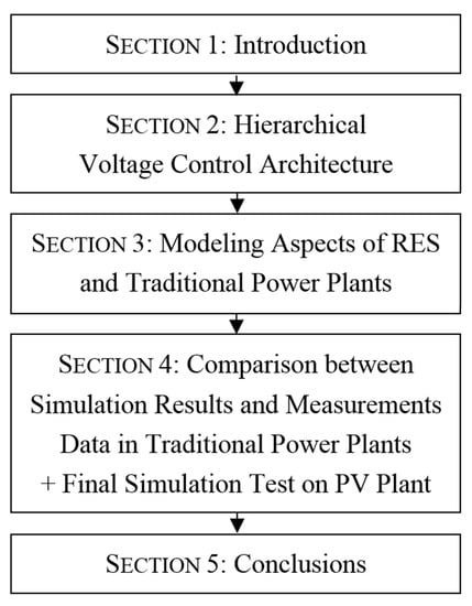
The paper is organized as follows. Section 2 describes the proposed architecture for the voltage control, while Section 3 is focused on modeling aspects, particularly on the differences in representing RES (where large PV power plant is a particular case) and traditional power plants. Then Section 4 discusses the main topic. Once demonstrated, the validity of the proposed methodology by comparing simulation results and measurements data from traditional power plants, such a methodology will be proficiently extended to the PV case. Finally, Section 5 provides a discussion about the obtained results, while Section 6 outlines the conclusions.
2. Hierarchical Voltage Control Architecture
In this paper, the voltage control strategy is based on a hierarchical architecture (Figure 1), where the main controller has been already proposed and utilized in several countries [46,47]. Therefore, the proposed strategy is based on an already implemented algorithm. Indeed, in the last 30 years this algorithm has proved its simple implementation, while at the same time it is scalable to transmission networks of different size and topology. For all these reasons, the application of such an algorithm has been extended to HV networks populated by nonprogrammable energy resources. The proposed architecture presents an external loop and a cluster of internal controllers, where the RPR behaves as a central control unit for coordinating the reactive power from each generator. Such a regulation is therefore adopted to obtain the voltage control on a peculiar pilot bus, named point of connection (POC). By implementing this control structure, the so-obtained reactive power regulation is actually similar to what is achieved by the SVR on transmission grids [48].
The control structure is explained in the scheme of Figure 1. Particularly, the network operator forwards the voltage reference to the control system, while the POC of the RES generation plant is operating as a pilot bus (as defined in SVR). In traditional fossil fuel power plants, all the generators are normally connected through a busbar, while in a more general case all generators are connected through any kind of grid, thus without any topology regularity. In the proposed architecture, the busbar voltage regulator (BVR) plays a crucial role, being responsible for the pilot bus voltage control (time constant Tb near ten seconds). Based on a classical PI (proportional-integral) functionality, the BVR can impose a level of reactive power (between −1 and +1) to be applied by each generator [48] for getting the requested voltage regulation. For particular cases in which the TSO implements a remote regional voltage control architecture, the TSO excludes the BVR function by directly sending an external reference signal to the reactive power control loop (i.e., switch in Figure 1). In both cases, the so-obtained signal is the input for the RPR, where the is multiplied by each generator reactive power limit to define the vector of reactive power references . The vector components are then compared to the actual reactive power values of each generator, thus determining a vector of errors . The latter is therefore multiplied by the dynamic decoupling (DD) matrix, whose outputs constitute the inputs for the generator reactive power regulators (GRPRs) [49], thus obtaining the reactive power control loop (i.e., the time constant is approximately few seconds). The reason for adopting the DD matrix is demonstrated by observing the MIMO (multiple-input-multiple-output) characteristic, which is typical of the generator reactive power control loop (i.e., several PI regulators, one for each generator). Instead, the dynamic decoupling matrix is capable of compensating for the mutual interactions, thus decoupling the MIMO reactive power control loop and consequently simplifying the control system design. Thus, the DD application allows the MIMO system to broken down into n single-input-single-output (SISO) loops, where the n generators are modeled by the same transfer function [49].
The control signals calculated by GRPRs are the references for each generator, which is represented as static frequency converter SFC and synchronous generators AVR in Figure 2. For what regards the control functionality ensured by BVR and RPR blocks, the related regulator parameters are to be set not only for decoupling internal and external control cycle but also for ensuring a voltage time response with an equivalent time constant of about 50 s. This value is chosen similar to what is usually required in conventional HV production power plants [50]. DGs are thus modeled as “voltage actuators” in terms of a first order mathematical model in d and q-axis coordinates. The time constant of voltage control loops is fast enough compared to that one of the outer reactive power loop (i.e., under the second), so can be assumed equal to . This model can be used for suitably studying the transient stability of the proposed hierarchical voltage control coupled with a simplified RES generator model (Figure 2) [51]. In the past, several studies have investigated the possibility of controlling the reactive power of a voltage source converter (VSC) independently from the active power. For instance, [52] not only shows the reactive power transient response in the presence of a changing in reactive power reference but also points out the P and Q injection decoupling. On the other hand, [53] exhibits a fast response for the reactive power control. This control algorithm can be applied on generation plants with different production technologies, coordinated by the same TSO. The application of the same control scheme allows a sort of uniformity in the dynamic responses of all generators. This control algorithm can be adopted in the case of generation plants with different production technologies, coordinated by the same TSO. Some examples are shown in [54,55,56], a cluster of hydropower plants, wind, and PV farms.
3. Power Plants Modeling
By observing Figure 1, the importance of the DD matrix appears undeniable, being capable of subdividing the initial system into n independent SISO subsystems. In this regard, the calculation of DD matrix is firstly shown in Section 3.1 for a generic distribution grid connecting all the generators (suitable for distributed RES production power plants). Then, the matrix is provided in Section 3.2 for the standard case, where large traditional generators are connected to the HV busbar through their step-up transformers (i.e., as in traditional large fossil fuel power plants).
3.1. Large RES Production Power Plants
As represented in Figure 3, the large RES production power plants are based on multiple small–medium generators, usually grouped as a medium voltage (MV) cluster interconnected to the single HV POC. This topology is common in practice, regardless of RES source (PV, wind, hydro, etc.) and generators technology (static, synchronous, asynchronous, etc.).
By adopting the well-known power flow equations, the MV distribution grid can be described by Equation (1), when considering active/reactive power for the node k:
where and are the active/reactive power at the node k, while and are the RMS voltage, respectively, at the node k and node i. The magnitude of admittance coefficients in branch is represented by , whereas and are the voltage phase angle at node k and node i. Finally, is the admittance phase of branch , whereas the total number of nodes constituting the analyzed grid. By considering the per-unit notation (i.e., rated values are the basis) and linearizing (1) at a given operating point, the Jacobian matrix is defined as in Equation (2):
By taking into account a behavior around the operating point, the partial derivatives matrices are the link between active/reactive power and magnitude/phase angle of voltage at buses. As a matter of fact, such matrix coefficients embed the information about the characteristic parameters of the network lines. For the purposes of voltage control, the last equation is to be particularized as in Equation (3), neglecting the active power variations ( and assuming the only reactive power sources as actuators [57]:
By setting a system-operating point, the power flow problem is solved, thus deducing the following equations for the linearized system:
where and are the vectors (n,1) of reactive power/voltage variations, whilst the (n,n) matrix models the electric coupling between reactive powers and voltage magnitudes. Hence, the generators are electrically coupled according to the coefficients (5):
In other words, a voltage variation at every network node causes a reactive power variation in all the nodes, according to the matrix coefficients, as expressed in Equation (6):
It is remarkable to notice that is considered full rank in the most practical applications, while the discussion of idiosyncratic cases (i.e., singular) is beyond the study aims. Finally, Equation (7) is capable of modeling the voltage at the POC, where is the vector (1,n) of the sensitivity coefficients for combining the POC to the network nodes:
Depending on the relative coefficients , the reactive power variation achieved at different grid nodes thus produces at the POC the voltage variation as in Equation (7). The matrix (n,n) and the vector (1,n) can also be determined by a numerical sensitivity analysis. Indeed, once all the network parameters are established and the reactive power of each DG plant is increased, the consequent voltage variation can be calculated as already discussed in [58]. On the other hand, by starting from the inverse of the electric coupling matrix, the dynamic decoupling matrix is found as in Equation (8). Such a matrix is then composed by the coefficients ; thus its definition is then given by Equation (9):
To finally calculate the constants values for the two PI controls, a traditional synthesis is sufficient, once the cascade system is determined. By observing Figure 1, the latter is constituted by the capability matrix, the decoupling matrix, the reactive power regulators, and finally the AVRs or SFCs.
3.2. Traditional Power Plants
The grid topology for a traditional power plant based on fossil fuel is offered in Figure 4, while Figure 5 shows the equivalent electrical model. By comparing the two topologies (i.e., Figure 3 RES versus Figure 4 traditional), the main difference is made manifest: the MV distribution grid in the RES power plant case. In the traditional power plant case, each generator is connected to the main busbar by the only generator transformer, which is characterized by a reactance [49]. This assumption is true even in the case of a generator directly connected to the main busbar, where the compound action provides , i.e., the equivalent reactance introduced by the control. Therefore, it is possible to categorize the traditional power plant as a subcase of the RES power plant case, where the internal distribution network is merely given by the reactance of generator transformers . In such a way, the electrical coupling of generators is only determined by the reactance of generator transformers and the equivalent reactance of upstream network , as clarified in [49]. In this perspective, the network topology represented in Figure 3 and its mathematical model constitutes the general case, albeit it is introduced for the RES case. As a matter of fact, this representation can describe a production power plant either based on RES or on traditional fossil sources. Therefore, the application of control strategy on traditional power plant is also a particular case of the RES production power plant.
For the traditional power plant case, the model can be attained by considering Figure 5. In such a case, the relation between generator voltage variations and reactive power variations is expressed with the algebraic relations (10):
where the quantities are expressed in the per unit notation. Particularly, is the reactance of the i-th generator transformer, while is the equivalent reactance of the upstream network. The symbol represents the voltage at the terminals of i-th generator and the reactive power of the i-th generator. Finally, is the voltage at POC to the transmission network. By expressing Equation (10) in matrix form, the important Equation (11) is determined. For a traditional electric plant, an additional important result is provided in Equation (12), where the elements of the dynamic decoupling matrix are clearly defined by the reactance and [49].
4. Case Studies
Currently, the proposed algorithm results are already implemented in Italian transmission systems (involving coal-fired and combined cycle gas power stations rated above 100 MVA) to achieve a coordinated production of reactive power [48]. In this section, the experimental data collected from the field for some traditional power plants equipped with a SART apparatus and the simulations for a large PV power plant are reported and compared. Three different power plant configurations are considered. In each of them, tests have been conducted applying at time t = 35 s a step in the signal. Simulations have been carried out adopting the proposed control system, according to the mathematical model presented in the third chapter. The mathematical model of the control has been implemented in DOME (a Python based simulation tool) [59], together with the models of the networks for the three cases. Three additional files (Case A, Case B and Case C) are made available as supplementary materials. Datasets and experimental details are in these files.
4.1. Case A) 940 MVA Combined-Cycle Power Plant
The combined-cycle power plant is composed of two identical groups, where each one has a synchro generator-gas turbine (300 MVA) and a synchro generator-steam turbine (170 MVA).
The considered power plant is connected to the Italian 400 kV transmission grid, whilst its topology is depicted in Figure 6. The effectiveness of the control (essentially a PI) is checked by analyzing the step response on the controlled variable reference (the reactive power level, ). The obtained results are reported in Figure 7, Figure 8, Figure 9, Figure 10, Figure 11 and Figure 12. Particularly, the correspondence between the simulated trends and the trends measured in the real plants can validate the proposed mathematical model. Such a correspondence between simulation and experimental data accredits the suitability of the adopted mathematical model.
By observing the last figures, it is possible to see the different level of reactive power reached by the groups two and four; this aspect obviously depends on the different size of groups two and four (170 MVA) in respect of the two twin gas generators of 300 MVA. Particularly, the SART system reactive requests are proportional to the reactive power capability of each generator. Each group changes its generated reactive power according to its capability curve and its generated active power (not shown). In the simulation, a little difference has been considered in the capability of groups one and three, while all active powers are kept constant during the simulations.
4.2. Case B) Synchronous Condenser of 160 MVA
This case considers a synchronous condenser rated 160 MVA, whose aim is mainly the reactive power production to compensate for voltage perturbations in the transmission network. The plant topology is depicted in Figure 13.
The obtained results are reported in the Figure 14, Figure 15, Figure 16 and Figure 17. In this case, the mathematical model is very simple. Experimental data and simulations are shown both for voltages and reactive powers. The correspondence between experimental data and simulations is shown as a proof of the correctness of the proposed mathematical model.
4.3. Case C) PV Power Plant of 46.8 MWp
The considered RES power plant [56] is a large PV plant with a peak power of 46.8 MWp. Particularly, the plant is composed of 82 photovoltaic subfields, each one rated about 0.57 MWp. Every subfield has its own inverter with a rated power of 0.5 MVA, connected to the 20 kV-internal distribution network by a transformer. The topology of the considered network is depicted in Figure 18, whereas all components are interfaced by using two different types of cables (in Figure 18 the two different types are drawn with different style according to Table 1). The lengths of all cables are in the order of hundreds of meters. All lengths have been taken into account in the mathematical model.
A single 132/20 kV transformer is used to step-up the voltage to the final HV bus, thus the single POC to the HV network. From the transmission grid point of view, the POC is seen as a unique generator similar to a traditional power plant. This PV power plant is traditionally operated at unity power factor, which is no longer considered satisfactory by the TSO. The presence of several generators based on inverters suggests the possibility of using their reactive capability for supporting the HV network voltage control through the proposed control. Additionally, in this PV power plant, a step in the reactive power level is applied as in the previous cases, while only simulation results are shown. In this regard, Figure 19 reports the p.u. reactive power (i.e., rated power as basis) of 6 representative PV inverters, where in total they amount to 82 unities. Each generator injects an amount of reactive power according to its rated power and its residual capability; therefore, the differences are almost negligible. By considering only one size for the inverters, the results are coherent. The voltage outputs of the considered inverters are shown in Figure 20, while the voltage profile at the POC is highlighted in Figure 21. The time responses show stable behaviors, whilst the dynamics result in accordance to the expected time constants. Finally, it possible to highlight the absence of cross dynamics disturbances between the different PV subfields.
5. Results and Discussion
By focusing on Case A and Case B, the good correspondence between simulated results and experimental data validates the mathematical models, then the way for representing power distribution grid and control architecture in DOME platform. This verified methodology can be then applied to the RES power plant (i.e., Case C), where the results are indeed consequent and thus capable of well-representing the dynamics of this kind of controlled power plant. It is interesting to highlight that both simulations and experimental data show a first-order behavior in presence of a reactive power reference step. On the other hand, the controlled voltage can reach the no-error steady-state condition without oscillations. In such a way, the group of generators (whether in parallel configuration or in star configuration) behaves as a single generator in a primary voltage regulation or as a group when coordinated by means of a secondary voltage regulation. Furthermore, Case C actually shows a behavior similar of what is observable in the presence of a standard power plant operating for a secondary voltage regulation. The latter is an important aspect in which the authors are interested in drawing attention. Finally, the proposed control methodology is not only applicable to the example of this paper but also it can be used when small–medium generators are interconnected to whichever distribution grid’s topology.
6. Conclusions
The proposed work has presented a coordinated voltage and reactive power control architecture. The control algorithm has been originated from well-known techniques, already widely used in the transmission network of many national systems for conventional power plants. The novelty is the capability of the algorithm in being adaptable to different technology, size, and topology of generating plants connected to the HV network. A mathematical model of the control system has been discussed and then implemented in DOME (a python-based simulation tool). Firstly, this implementation has been used to simulate the dynamical behavior of traditional power plants, and experimental data have been compared to validate the control system model. Thus, the validated control system model has been applied to a large PV power plant, where numerical simulations have verified the behavior. The performed simulations have demonstrated how a large controlled PV field exhibits an asymptotically stable behavior, in terms of voltage and reactive power. Moreover, the PV dynamics (i.e., time constants) are fully comparable to the ones of large traditional power plants, which are involved in coordinated voltage and reactive power controls in HV networks. Therefore, the reactive capability of PV power plants and large power stations can be synergistically exploited, while keeping a uniform dynamic performance.
The proposed control scheme is finally characterized by several advantages: it is capable of ensuring a fast response, while performing a perfect tracking of both the HV bus voltage and RES reactive powers. In addition, there is no steady-state error and the system dynamics does not highlight oscillations. Each generator participates in the control by sharing its reactive power (in absorption or injection), where the provided quota is proportional to its capability at the point of operation. An important note to be highlighted regards the communication data. The proposed control strategy is based on the communication of a single control signal (i.e., the reactive power level) to all the generators involved, thus making its implementation rather simple. The transmitted value is coherent to the reactive power level’s control signal that is already in use in the coordinated voltage and reactive power control of transmission networks. This makes the proposed control architecture fully compatible with existing ones. As a further development, authors are investigating how this control architecture can be scaled and integrated into distribution networks. In a glance, the proposed control is characterized by the two important pros: a) only one signal is requested for regulating multiple-generators and b) it is strictly alike to the secondary control already used in transmission system, thus consequently it is compatible. The proposed solution is feasible when promoting the integration of large PV systems in the HV networks’ control strategies (i.e., voltage and reactive power).
Supplementary Materials
The following are available online at https://www.mdpi.com/1996-1073/13/10/2441/s1, File S1: Case A.dm, File S2: Case B.dm, File S3: Case C.dm. Three additional files (Case A, Case B and Case C) are made available during the submission process. Full datasets and full experimental details are provided in these three files. The three files are the inputs for performing simulations then reproducing the results in DOME, the Python based simulation tool used in this paper.
Author Contributions
Conceptualization, M.C., D.B. and G.S.; Data curation, M.C. and R.C.; Formal analysis, R.C.; Methodology, D.B. and G.S.; Software, M.C.; Supervision, G.S.; Validation, D.B.; Visualization, R.C.; Writing—original draft, R.C.; Writing—review & editing, M.C., D.B. and G.S. All authors have read and agreed to the published version of the manuscript.
Funding
This research received no external funding.
Conflicts of Interest
The authors declare no conflict of interest.
Abbreviations
| AVR | Automatic Voltage Regulator |
| BVR | Busbar Voltage Regulator |
| DD | Dynamic Decoupling |
| DGs | Distributed Generators |
| GRPRs | Generator Reactive Power Regulators |
| HV | High Voltage |
| LV | Low Voltage |
| MIMO | Multiple-Input-Multiple-Output |
| MV | Medium Voltage |
| PI | Proportional-Integral |
| POC | Point Of Connection |
| PV | Photovoltaic |
| RES | Renewable Energy Sources |
| RPR | Reactive Power Regulator |
| SFC | Static Frequency Converter |
| SISO | Single-Input-Single-Output |
| STATCOM | Static Synchronous Compensator |
| SVR | Secondary Voltage Regulation |
| TSO | Transmission System Operator |
| VPP | Virtual Power Plants |
| VSC | Voltage Source Converter |
| VSN | Virtual Smart Network |
References
- van Wyk, A.A.L.; Khan, M.A.; Barendse, P. Impact of over/under and voltage unbalanced supplies on Energy-Efficient motors. In Proceedings of the 2011 IEEE International Electric Machines & Drives Conference (IEMDC), Niagara Falls, ON, Canada, 15–18 May 2011; pp. 1380–1385. [Google Scholar]
- Jahmeerbacus, I.; Bhurtun, C. Energy efficiency and power quality issues of AC voltage controllers in instant water heaters. In Proceedings of the 2012 20th Domestic Use of Energy Conference, Cape Town, South Africa, 3–4 April 2012; pp. 139–144. [Google Scholar]
- Lipsky, A.; Braunstein, A.; Miteva, N.; Slonim, M. Electric power quality and efficiency of power supply. In Proceedings of the 21st IEEE Convention of the Electrical and Electronic Engineers in Israel. Proceedings (Cat. No.00EX377), Tel-Aviv, Israel, 11–12 April 2000; pp. 222–225. [Google Scholar]
- Fusco, G.; Russo, M. Adaptive Voltage Control System; Springer: Berlin/Heidelberg, Germany, 2007. [Google Scholar]
- Chiandone, M.; Sulligoi, G.; Massucco, S.; Silvestro, F. Hierarchical voltage regulation of transmission systems with renewable power plants: An overview of the Italian case. In Proceedings of the 3rd Renewable Power Generation Conference (RPG 2014), Naples, Italy, 24–25 September 2014; pp. 1–5. [Google Scholar]
- Mousavi, O.A.; Cherkaoui, R. Literature Survey on Fundamental Issues of Voltage and Reactive Power Control; École polytechnique fédérale de Lausanne: Lausanne, Switzerland, 2011. [Google Scholar]
- Mohandes, B.; el Moursi, M.S.; Hatziargyriou, N.D.; el Khatib, S. A review of power system flexibility with high penetration of renewables. IEEE Trans. Power Syst. 2019, 34, 3140–3155. [Google Scholar] [CrossRef]
- Sun, H.; Guo, Q.; Qi, J.; Ajjarapu, V.; Bravo, R.; Chow, J.; Li, Z.; Moghe, R.; Nasr-Azadani, E.; Tamrakar, U.; et al. Review of challenges and research opportunities for voltage control in smart grids. IEEE Trans. Power Syst. 2019, 34, 2790–2801. [Google Scholar] [CrossRef] [Green Version]
- Vita, V.; Alimardan, T.; Ekonomou, L. The impact of distributed generation in the distribution networks’ voltage profile and energy losses. In Proceedings of the 9th IEEE European Modelling Symposium on Mathematical Modelling and Computer Simulation, Madrid, Spain, 6–8 October 2015; pp. 260–265. [Google Scholar]
- Ceaki, O.; Seritan, G.; Vatu, R.; Mancasi, M. Analysis of power quality improvement in smart grids. In Proceedings of the 10th International Symposium on Advanced Topics in Electrical Engineering (ATEE), Bucharest, Romania, 23–25 March 2017; pp. 797–801. [Google Scholar]
- Nieto, A.; Vita, V.; Maris, T.I. Power quality improvement in power grids with the integration of energy storage systems. Int. J. Eng. Res. Technol. 2016, 5, 438–443. [Google Scholar]
- European Commission. EU Energy in Figures—Statistical Pocketbook 2016; Publications Office of the European Union: Brussels, Belgium, 2016.
- The International Renewable Energy Agency. Renewable Energy Statistics 2016; IRENA: Abu Dhabi, UAE, 2016. [Google Scholar]
- Renewable Energy Policy Network for the 21st Century (REN21). Renewables 2014 Global Status Report; REN21: Paris, France, 2014. [Google Scholar]
- GSE S.p.A. Rapporto Statistico 2014—Solare Fotovoltaico; GSE S.p.A.: Rome, Italy, 2015. [Google Scholar]
- Petinrin, J.O.; Shaaban, M. Impact of renewable generation on voltage control in distribution systems. Renew. Sustain. Energy Rev. 2016, 65, 770–783. [Google Scholar] [CrossRef]
- Pfeiffer, R. Brief status on CENELEC standards related to Connection Network Code. In Proceedings of the 3rd Grid Connection Stakeholder Committee Meeting, Brussels, Belgium, 8 September 2016. [Google Scholar]
- Bründlinger, R. Advanced smart inverter and DER functions Requirements in latest European Grid Codes and future trends. In Proceedings of the Solar Canada 2015 Conference, Toronto, ON, Canada, 7–8 December 2015. [Google Scholar]
- ENTSO-E. Implementation Guideline for Network Code “Requirements for Grid Connection Applicable to all Generators”; ENTSO-E: Brussels, Belgium, 2013. [Google Scholar]
- The European Commission. Commission Regulation (EU) 2016/631 of 14 April 2016 Establishing a Network Code on Requirements for Grid Connection of Generators; Official Journal of the European Union: Brussels, Belgium, 2016. [Google Scholar]
- Arrinda, J.; Barrena, J.A.; Rodríguez, M.A.; Guerrero, A. Analysis of massive integration of renewable power plants under new regulatory frameworks. In Proceedings of the 2014 International Conference on Renewable Energy Research and Application (ICRERA), Milwaukee, WI, USA, 19–22 October 2014; pp. 462–467. [Google Scholar]
- Varma, R.K.; Salama, M. Large-scale photovoltaic solar power integration in transmission and distribution networks. In Proceedings of the 2011 IEEE Power and Energy Society General Meeting, Detroit, MI, USA, 24–28 July 2011; pp. 1–4. [Google Scholar]
- Delfino, F.; Procopio, R.; Rossi, M.; Ronda, G. Integration of large-size photovoltaic systems into the distribution grids: A P-Q chart approach to assess reactive support capability. IET Renew. Power Gener. 2010, 4, 329–340. [Google Scholar] [CrossRef]
- Tyll, H.K.; Schettle, F. Historical overview on dynamic reactive power compensation solutions from the begin of AC power transmission towards present applications. In Proceedings of the 2009 IEEE/PES Power Systems Conference and Exposition, Seattle, WA, USA, 15–18 March 2009; pp. 1–7. [Google Scholar]
- Ghasemi, M.A.; Parniani, M. Prevention of distribution network overvoltage by adaptive droop-based active and reactive power control of PV systems. Electric Power Syst. Res. 2016, 133, 313–327. [Google Scholar] [CrossRef]
- Hashemi, M.; Agelidis, V. Evaluation of voltage regulation mitigation methods due to high penetration of PV generation in residential areas. In Proceedings of the 2013 International Conference on Renewable Energy Research and Applications (ICRERA), Madrid, Spain, 20–23 October 2013; pp. 1180–1189. [Google Scholar]
- Hasheminamin, M.; Agelidis, V.G.; Ahmadi, A.; Siano, P.; Teodorescu, R. Single-point reactive power control method on voltage rise mitigation in residential networks with high PV penetration. Renew. Energy 2018, 119, 504–512. [Google Scholar] [CrossRef]
- Rallabandi, V.; Akeyo, O.M.; Ionel, D.M. Modeling of a multi-megawatt grid connected PV system with integrated batteries. In Proceedings of the 2016 IEEE International Conference on Renewable Energy Research and Applications (ICRERA), Birmingham, UK, 20–23 November 2016; pp. 1146–1151. [Google Scholar]
- Olival, P.C.; Madureira, A.G.; Matos, M. Advanced voltage control for smart microgrids using distributed energy resources. Electr. Power Syst. Res. 2017, 146, 132–140. [Google Scholar] [CrossRef]
- Jayasekara, N.; Wolfs, P.; Masoum, M.A.S. An optimal management strategy for distributed storages in distribution networks with high penetrations of PV. Electr. Power Syst. Res. 2014, 116, 147–157. [Google Scholar] [CrossRef]
- Ko, H.; Bruey, S.; Jatskevich, J.; Dumont, G.; Moshref, A. A PI Control of DFIG-Based Wind Farm for Voltage Regulation at Remote Location. In Proceedings of the 2007 IEEE Power Engineering Society General Meeting, Tampa, FL, USA, 24–28 June 2007; pp. 1–6. [Google Scholar]
- Baalbergen, F.; Gibescu, M.; van der Sluis, L. Voltage stability consequences of decentralized generation and possibilities for intelligent control. In Proceedings of the 2010 IEEE PES Innovative Smart Grid Technologies Conference Europe (ISGT Europe), Gothenburg, Sweden, 11–13 October 2010; pp. 1–8. [Google Scholar]
- Zhao, J.; Li, X.; Hao, J.; Lu, J. Reactive power control of wind farm made up with doubly fed induction generators in distribution system. Electr. Power Syst. Res. 2010, 80, 698–706. [Google Scholar] [CrossRef]
- El-Fouly, T.H.M.; El-Saadany, E.F.; Salama, M.M.A. Voltage regulation of wind farms equipped with variable-speed doubly-fed induction generators wind turbines. In Proceedings of the 2007 IEEE Power Engineering Society General Meeting, Tampa, FL, USA, 24–28 June 2007; pp. 1–8. [Google Scholar]
- Qin, N.; Bak, C.L.; Abildgaard, H. Automatic voltage control system with market price employing large wind farms. Electr. Power Syst. Res. 2018, 157, 93–105. [Google Scholar] [CrossRef]
- Mastromauro, R.A.; Orlando, N.A.; Ricchiuto, D.; Liserre, M.; Dell’Aquila, A. Hierarchical control of a small wind turbine system for active integration in LV distribution network. In Proceedings of the 2013 International Conference on Clean Electrical Power (ICCEP), Alghero, Italy, 11–13 June 2013; pp. 426–433. [Google Scholar]
- Koraki, D.; Strunz, K. Wind and solar power integration in electricity markets and distribution networks through service-centric virtual power plants. IEEE Trans. Power Syst. 2018, 33, 473–485. [Google Scholar] [CrossRef]
- Unger, D.; Spitalny, L.; Myrzik, J.M.A. Voltage control by small hydro power plants integrated into a virtual power plant. In Proceedings of the 2012 IEEE Energytech, Cleveland, OH, USA, 29–31 May 2012; pp. 1–6. [Google Scholar]
- Dielmann, K.; van der Velden, A. Virtual power plants (VPP)—A new perspective for energy generation? In Proceedings of the 9th International Scientific and Practical Conference of Students, Post-graduates Modern Techniques and Technologies, 2003, MTT 2003, Tomsk, Russia, 7–11 April 2003. [Google Scholar]
- Pudjianto, D.; Ramsay, C.; Strbac, G. Virtual power plant and system integration of distributed energy resources. IET Renew. Power Gener. 2007, 1, 10–16. [Google Scholar] [CrossRef]
- Ricerca Sistema Energetico (RSE). Definizione dei Concetti e Delle Architetture di Gestione, Controllo e Comunicazione di Microreti e Virtual Power Plant; Progetto RdS—Trasmissione e Distribuzione; RSE: Milan, Italy, 2006. [Google Scholar]
- Arcidiacono, V. Automatic Voltage and Reactive Power Control in Transmission Systems. In Proceedings of the 1983 CIGRE-IFAC Symposium, Florence, Italy, 26–28 September 1983. Survey paper. [Google Scholar]
- Paul, J.P.; Leost, J.Y.; Tesseron, J.M. Survey of the Secondary Voltage Control in France: Present Realization and Investigations. IEEE Trans. Power Syst. 1987, 2, 505–511. [Google Scholar] [CrossRef]
- Sancha, J.L.; Fernandez, J.L.; Cortes, A.; Abarca, J.T. Secondary voltage control: Analysis, solutions and simulation results for the Spanish transmission system. IEEE Trans. Power Syst. 1996, 11, 630–638. [Google Scholar] [CrossRef]
- Automatic System for Voltage Regulation (SART) for Electric Power Plant, GRTN Document nr. DRRPX03019. Available online: http://www.terna.it/LinkClick.aspx?fileticket=irZ1FD%2BYxUE%3D&tabid=106&mid=468 (accessed on 11 April 2020).
- Lagonotte, P.; Sabonnadiere, J.C.; Leost, J.Y.; Paul, J.P. Structural analysis of the electrical system: Application to secondary voltage control in France. IEEE Trans. Power Syst. 1989, 4, 479–486. [Google Scholar] [CrossRef]
- Sancha, J.L.; Fernandez, J.L.; Martinez, F.; Salle, C. Spanish practices in reactive power management and voltage control. In Proceedings of the IEE Colloquium on International Practices in Reactive Power Control, London, UK, 7 April 1993; pp. 3/1–3/4. [Google Scholar]
- Sulligoi, G.; Chiandone, M.; Arcidiacono, V. NewSART automatic voltage and reactive power regulator for secondary voltage regulation: Design and application. In Proceedings of the 2011 IEEE Power and Energy Society General Meeting, San Diego, CA, USA, 24–28 July 2011; pp. 1–7. [Google Scholar]
- Arcidiacono, V.; Menis, R.; Sulligoi, G. Improving power quality in all electric ships using a voltage and VAR integrated regulator. In Proceedings of the 2007 IEEE Electric Ship Technologies Symposium, Arlington, VA, USA, 21–23 May 2007; pp. 322–327. [Google Scholar]
- TERNA. Sistema Automatico per la Regolazione di Tensione (SART) per Centrali Elettriche di Produzione. Annex A16 to the National Grid Code, GRTN Document nr. DRRPX03019. Available online: http://collaudo.download.terna.it/terna/0000/0105/33.pdf(accessed on 11 April 2020).
- Tamimi, B.; Cañizares, C.; Bhattacharya, K. Modeling and performance analysis of large solar photo-voltaic generation on voltage stability and inter-area oscillations. In Proceedings of the 2011 IEEE Power and Energy Society General Meeting, San Diego, CA, USA, 24–28 July 2011; pp. 1–6. [Google Scholar]
- Vasquez, J.C.; Mastromauro, R.A.; Liserre, J.M. Voltage support provided by a droop-controlled multifunctional inverter. IEEE Trans. Ind. Electron. 2009, 56, 4510–4519. [Google Scholar] [CrossRef]
- Cagnano, A.; De Tuglie, E.; Liserre, M.; Mastromauro, R.A. Online Optimal Reactive Power Control Strategy of PV Inverters. IEEE Trans. Ind. Electron. 2011, 58, 4549–4558. [Google Scholar] [CrossRef]
- Campaner, R.; Chiandone, M.; Arcidiacono, V.; Sulligoi, G.; Milano, F. Automatic voltage control of a cluster of hydro power plants to operate as a virtual power plant. In Proceedings of the 2015 IEEE 15th International Conference on Environment and Electrical Engineering (EEEIC), Rome, Italy, 10–13 June 2015; pp. 2153–2158. [Google Scholar]
- Chiandone, M.; Campaner, R.; Arcidiacono, V.; Sulligoi, G.; Milano, F. Automatic voltage and reactive power regulator for wind farms participating to TSO voltage regulation. In Proceedings of the 2015 IEEE Eindhoven PowerTech, Eindhoven, The Netherlands, 29 June–2 July 2015; pp. 1–5. [Google Scholar]
- Chiandone, M.; Campaner, R.; Pavan, A.M.; Arcidiacono, V.; Milano, F.; Sulligoi, G. Coordinated voltage control of multi-converter power plants operating in transmission systems. The case of photovoltaics. In Proceedings of the 2015 International Conference on Clean Electrical Power (ICCEP), Taormina, Italy, 16–18 June 2015; pp. 506–510. [Google Scholar]
- Gao, B.; Morison, G.K.; Kundur, P. Voltage Stability evaluation using modal analysis. IEEE Trans. Power Syst. 1992, 7, 1529–1542. [Google Scholar] [CrossRef]
- Carvalho, P.M.; Correia, P.F.; Ferreira, L.A. Distributed reactive power generation control for voltage rise mitigation in distribution networks. IEEE Trans. Power Syst. 2008, 23, 766–772. [Google Scholar] [CrossRef]
- Milano, F. A python-based software tool for power system analysis. In Proceedings of the IEEE PES General Meeting, Vancouver, BC, Canada, 21–25 July 2013. [Google Scholar]
Figure 1.
Synoptic scheme of secondary voltage control applied to a general case where all generators are connected by means of a distribution grid with a given topology.
Figure 1.
Synoptic scheme of secondary voltage control applied to a general case where all generators are connected by means of a distribution grid with a given topology.

Figure 2.
Distributed Generator model.

Figure 3.
The topology of a renewable energy sources (RES) power plant composed of a medium voltage (MV) network and a unique point of connection (POC) to the high voltage (HV) network.
Figure 3.
The topology of a renewable energy sources (RES) power plant composed of a medium voltage (MV) network and a unique point of connection (POC) to the high voltage (HV) network.

Figure 4.
The typical topology of a traditional power plant: several generators parallel-connected to a busbar.
Figure 4.
The typical topology of a traditional power plant: several generators parallel-connected to a busbar.

Figure 5.
Equivalent electrical model.

Figure 6.
The topology of plant A.

Figure 7.
Generators reactive powers response (in p.u.) to a step in the reactive power level reference (experimental data).
Figure 7.
Generators reactive powers response (in p.u.) to a step in the reactive power level reference (experimental data).

Figure 8.
Generators reactive powers response (in p.u.) to a step in the reactive power level reference (simulated data).
Figure 8.
Generators reactive powers response (in p.u.) to a step in the reactive power level reference (simulated data).

Figure 9.
Voltage profile (in p.u.) at the different nodes of generation (experimental data).

Figure 10.
Voltage profile (in p.u.) at the different nodes of generation (simulated data).

Figure 11.
Voltage profile (in p.u.) at the POC (experimental data).

Figure 12.
Voltage profile (in p.u.) at the POC (simulated data).

Figure 13.
The topology of plant B.

Figure 14.
Reactive power profile (in p.u.) of a generator (experimental data).

Figure 15.
Reactive power profile (in p.u.) of a generator (simulated data).

Figure 16.
Voltage profile (in p.u.) at the POC (experimental data).

Figure 17.
Voltage profile (in p.u.) at the POC (simulated data).

Figure 18.
The topology of photovoltaic (PV) power plant, plant C.

Figure 19.
Reactive power profile (in p.u.) of six representative PV inverters (simulated data).

Figure 20.
Voltage profile (in p.u.) at the six representative PV inverters output (simulated data).
Figure 20.
Voltage profile (in p.u.) at the six representative PV inverters output (simulated data).

Figure 21.
Voltage profile (in p.u.) at the POC (simulated data).


Table 1.
Cable types.
| Line Type | Graphic Symbol | R | X | C |
|---|---|---|---|---|
| (Ω/km) | (Ω/km) | (μF/km) | ||
| RG7H1R 3 × 1 × 240 mm2 |  | 0.0754 | 0.12 | 0.25 |
| RG7H1R 3 × 1 × 120 mm2 |  | 0.153 | 0.11 | 0.32 |
© 2020 by the authors. Licensee MDPI, Basel, Switzerland. This article is an open access article distributed under the terms and conditions of the Creative Commons Attribution (CC BY) license (http://creativecommons.org/licenses/by/4.0/).
Share and Cite
MDPI and ACS Style
Chiandone, M.; Campaner, R.; Bosich, D.; Sulligoi, G. A Coordinated Voltage and Reactive Power Control Architecture for Large PV Power Plants. Energies 2020, 13, 2441. https://doi.org/10.3390/en13102441
AMA Style
Chiandone M, Campaner R, Bosich D, Sulligoi G. A Coordinated Voltage and Reactive Power Control Architecture for Large PV Power Plants. Energies. 2020; 13(10):2441. https://doi.org/10.3390/en13102441
Chicago/Turabian StyleChiandone, Massimiliano, Riccardo Campaner, Daniele Bosich, and Giorgio Sulligoi. 2020. "A Coordinated Voltage and Reactive Power Control Architecture for Large PV Power Plants" Energies 13, no. 10: 2441. https://doi.org/10.3390/en13102441
Note that from the first issue of 2016, this journal uses article numbers instead of page numbers. See further details here.