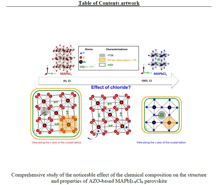
Influence of Chloride/Iodide Ratio in MAPbI3-xClx Perovskite Solar Devices: Case of Low Temperature Processable AZO Sub-Layer


 , ,
, , 
Abstract
:
1. Introduction
2. Materials and Methods
3. Results and Discussion
4. Conclusions
Supplementary Materials
Author Contributions
Funding
Acknowledgments
Conflicts of Interest
References
- Stranks, S.D.; Eperon, G.E.; Grancini, G.; Menelaou, C.; Alcocer, M.J.P.; Leijtens, T.; Herz, L.M.; Petrozza, A.; Snaith, H.J. Electron-Hole Diffusion Lengths Exceeding 1 micrometer in an organometal trihalide Perovskite Absorber. Science 2013, 342, 341–344. [Google Scholar] [CrossRef] [Green Version]
- Sum, T.C.; Mathews, N. Advancements in perovskite solar cells: Photophysics behind the photovoltaics. Energy Environ. Sci. 2014, 7, 2518–2534. [Google Scholar] [CrossRef] [Green Version]
- National Renewable Energy Laboratory (NREL). Best Research-Cell Efficiencies; National Renewable Energy Laboratory (NREL): Golden, CO, USA, 2019. [Google Scholar]
- Wang, Q.; Lyu, M.; Zhang, M.; Yun, J.-H.; Chen, H.; Wang, L. Transition from the Tetragonal to Cubic Phase of Organohalide Perovskite: The Role of Chlorine in Crystal Formation of CH3NH3PbI3 on TiO2 Substrates. J. Phys. Chem. Lett. 2015, 6, 4379–4384. [Google Scholar] [CrossRef] [PubMed]
- Kim, H.S.; Lee, C.R.; Im, J.H.; Lee, K.B.; Moehl, T.; Marchioro, A.; Moon, S.J.; Humphry-Baker, R.; Yum, J.H.; Moser, J.E.; et al. Lead iodide perovskite sensitized all-solid-state submicron thin film mesoscopic solar cell with efficiency exceeding 9%. Sci. Rep. 2012, 2, 591. [Google Scholar] [CrossRef] [PubMed] [Green Version]
- Chen, Q.; Zhou, H.; Hong, Z.; Luo, S.; Duan, H.S.; Wang, H.H.; Liu, Y.; Li, G.; Yang, Y. Planar heterojunction perovskite solar cells via vapor-assisted solution process. J. Am. Chem. Soc. 2014, 136, 622–625. [Google Scholar] [CrossRef]
- Tao, C.; Neutzner, S.; Colella, L.; Marras, S.; Srimath Kandada, A.R.; Gandini, M.; De Bastiani, M.; Pace, G.; Manna, L.; Caironi, M.; et al. 17.6% Stabilized Efficiency in Low-Temperature Processed Planar Perovskite Solar Cells. Energy Environ. Sci. 2015, 8, 2365–2370. [Google Scholar] [CrossRef] [Green Version]
- Saliba, M.; Correa-Baena, J.P.; Wolff, C.M.; Stolterfoht, M.; Phung, N.; Albrecht, S.; Neher, D.; Abate, A. How to Make over 20% Efficient Perovskite Solar Cells in Regular (n-i-p) and Inverted (p-i-n) Architectures. Chem. Mater. 2018, 30, 4193–4201. [Google Scholar] [CrossRef]
- Mahmood, K.; Swain, B.S.; Amassian, A. 16.1% Efficient Hysteresis-Free Mesostructured Perovskite Solar Cells Based on Synergistically Improved ZnO Nanorod Arrays. Adv. Energy Mater. 2015, 5, 1–11. [Google Scholar] [CrossRef]
- Pang, Z.; Sun, Y.; Gao, Y.; Zhang, X.; Sun, Y.; Yang, J. Unravelling the mechanism of interface passivation engineering for achieving high-efficient ZnO-based planar perovskite solar cells. J. Power Sources 2019, 438, 226957. [Google Scholar] [CrossRef]
- Spalla, M.; Planes, E.; Perrin, L.; Matheron, M.; Berson, S.; Flandin, L. Alternative Electron Transport Layer Based on Al-Doped ZnO and SnO2 for Perovskite Solar Cells: Impact on Microstructure and Stability. ACS Appl. Energy Mater. 2019, 2, 7183–7195. [Google Scholar] [CrossRef]
- Planes, E.; Spalla, M.; Juillard, S.; Perrin, L.; Flandin, L. Absolute Quantification of Photo-/Electroluminescence Imaging for Solar Cells: Definition and Application to Organic and Perovskite Devices. ACS Appl. Electron. Mater. 2019, 1, 2489–2501. [Google Scholar] [CrossRef]
- Liu, D.; Wang, Y.; Xu, H.; Zheng, H.; Zhang, T.; Zhang, P.; Wang, F.; Wu, J.; Wang, Z.; Chen, Z.; et al. SnO2-Based Perovskite Solar Cells: Configuration Design and Performance Improvement. Sol. RRL 2019, 3, 1800292. [Google Scholar] [CrossRef]
- Jiang, Q.; Zhang, X.; You, J. SnO2: A Wonderful Electron Transport Layer for Perovskite Solar Cells. Small 2018, 14, 1801154. [Google Scholar] [CrossRef] [PubMed]
- Xiong, L.; Guo, Y.; Wen, J.; Liu, H.; Yang, G.; Qin, P.; Fang, G. Review on the Application of SnO2 in Perovskite Solar Cells. Adv. Funct. Mater. 2018, 28, 1802757. [Google Scholar] [CrossRef]
- Yang, J.; Siempelkamp, B.D.; Mosconi, E.; De Angelis, F.; Kelly, T.L. Origin of the Thermal Instability in CH3NH3PbI3 Thin Films Deposited on ZnO. Chem. Mater. 2015, 27, 4229–4236. [Google Scholar] [CrossRef]
- Seo, S.; Jeong, S.; Bae, C.; Park, N.G.; Shin, H. Perovskite Solar Cells with Inorganic Electron- and Hole-Transport Layers Exhibiting Long-Term (≈500 h) Stability at 85 °C under Continuous 1 Sun Illumination in Ambient Air. Adv. Mater. 2018, 30, 1–8. [Google Scholar] [CrossRef]
- Baltakesmez, A.; Biber, M.; Tüzemen, S. Inverted planar perovskite solar cells based on Al doped ZnO substrate. J. Radiat. Res. Appl. Sci. 2017, 11, 124–129. [Google Scholar] [CrossRef] [Green Version]
- Tseng, Z.L.; Chiang, C.H.; Chang, S.H.; Wu, C.G. Surface engineering of ZnO electron transporting layer via Al doping for high efficiency planar perovskite solar cells. Nano Energy 2016, 28, 311–318. [Google Scholar] [CrossRef]
- Chouhan, A.S.; Jasti, N.P.; Avasthi, S. Surface Modification of Aluminum Doped Zinc Oxide by Ozone-Gas Treatment for Perovskite Solar Cells. In Proceedings of the nanoGe International Conference on Perovskite Solar Cells, Photonics and Optoelectronics (NIPHO19), Jerusalem, Israel, 24–27 February 2019. [Google Scholar] [CrossRef]
- Wu, S.H.; Lin, M.Y.; Chang, S.H.; Tu, W.C.; Chu, C.W.; Chang, Y.C. A Design Based on a Charge-Transfer Bilayer as an Electron Transport Layer for Improving the Performance and Stability in Planar Perovskite Solar Cells. J. Phys. Chem. C 2018, 122, 236–244. [Google Scholar] [CrossRef]
- Zhao, X.; Shen, H.; Zhang, Y.; Li, X.; Zhao, X.; Tai, M.; Li, J.; Li, J.; Li, X.; Lin, H. Aluminum-Doped Zinc Oxide as Highly Stable Electron Collection Layer for Perovskite Solar Cells. ACS Appl. Mater. Interfaces 2016, 8, 7826–7833. [Google Scholar] [CrossRef]
- Dong, Q.; Ho, C.H.Y.; Yu, H.; Salehi, A.; So, F. Defect Passivation by Fullerene Derivative in Perovskite Solar Cells with Aluminum-doped Zinc Oxide as Electron Transporting Layer. Chem. Mater. 2019, 31, 6833–6840. [Google Scholar] [CrossRef]
- Matsui, T.; Yokoyama, T.; Negami, T.; Sekiguchi, T.; Saliba, M.; Grätzel, M.; Segawa, H. Effect of rubidium for thermal stability of triple-cation perovskite solar cells. Chem. Lett. 2018, 47, 814–816. [Google Scholar] [CrossRef]
- Saliba, M.; Matsui, T.; Seo, J.Y.; Domanski, K.; Correa-Baena, J.P.; Nazeeruddin, M.K.; Zakeeruddin, S.M.; Tress, W.; Abate, A.; Hagfeldt, A.; et al. Cesium-containing triple cation perovskite solar cells: Improved stability, reproducibility and high efficiency. Energy Environ. Sci. 2016, 9, 1989–1997. [Google Scholar] [CrossRef] [PubMed] [Green Version]
- Zimmermann, I.; Gratia, P.; Martineau, D.; Grancini, G.; Audinot, J.N.; Wirtz, T.; Nazeeruddin, M.K. Improved efficiency and reduced hysteresis in ultra-stable fully printable mesoscopic perovskite solar cells through incorporation of CuSCN into the perovskite layer. J. Mater. Chem. A 2019, 7, 8073–8077. [Google Scholar] [CrossRef]
- Yu, H.; Wang, F.; Xie, F.; Li, W.; Chen, J.; Zhao, N. The Role of Chlorine in the Formation Process of “CH3NH3PbI3-xClx” Perovskite. Adv. Funct. Mater. 2014, 24, 7102–7108. [Google Scholar] [CrossRef]
- Li, Z.; Kolodziej, C.; McCleese, C.; Wang, L.; Kovalsky, A.; Samia, A.C.; Zhao, Y.; Burda, C. Effect of chloride substitution on interfacial charge transfer processes in MAPbI 3 perovskite thin film solar cells: Planar versus mesoporous. Nanoscale Adv. 2019, 1, 827–833. [Google Scholar] [CrossRef] [Green Version]
- Xie, F.X.; Su, H.; Mao, J.; Wong, K.S.; Choy, W.C.H. Evolution of diffusion length and trap state induced by chloride in perovskite solar cell. J. Phys. Chem. C 2016, 120, 21248–21253. [Google Scholar] [CrossRef]
- De Quilettes, D.W.; Vorpahl, S.M.; Stranks, S.D.; Nagaoka, H.; Eperon, G.E.; Ziffer, M.E.; Snaith, H.J.; Ginger, D.S. Impact of micro structure on local carrier lifetime in perovskite solar cells. Sci. Rep. 2015, 348, 683–686. [Google Scholar]
- Fan, L.; Ding, Y.; Luo, J.; Shi, B.; Yao, X.; Wei, C.; Zhang, D.; Wang, G.; Sheng, Y.; Chen, Y.; et al. Elucidating the role of chlorine in perovskite solar cells. J. Mater. Chem. A 2017, 5, 7423–7432. [Google Scholar] [CrossRef]
- Colella, S.; Mosconi, E.; Fedeli, P.; Listorti, A.; Gazza, F.; Orlandi, F.; Ferro, P.; Besagni, T.; Rizzo, A.; Calestani, G.; et al. MAPbI3-xClx mixed halide perovskite for hybrid solar cells: The role of chloride as dopant on the transport and structural properties. Chem. Mater. 2013, 25, 4613–4618. [Google Scholar] [CrossRef]
- Colella, S.; Mosconi, E.; Pellegrino, G.; Alberti, A.; Guerra, V.L.P.; Masi, S.; Listorti, A.; Rizzo, A.; Condorelli, G.G.; De Angelis, F.; et al. Elusive presence of chloride in mixed halide perovskite solar cells. J. Phys. Chem. Lett. 2014, 5, 3532–3538. [Google Scholar] [CrossRef] [PubMed]
- Park, B.W.; Zhang, X.; Johansson, E.M.J.; Hagfeldt, A.; Boschloo, G.; Seok, S., Il; Edvinsson, T. Analysis of crystalline phases and integration modelling of charge quenching yields in hybrid lead halide perovskite solar cell materials. Nano Energy 2017, 40, 596–606. [Google Scholar] [CrossRef]
- Tombe, S.; Adam, G.; Heilbrunner, H.; Yumusak, C.; Apaydin, D.H.; Hailegnaw, B.; Ulbricht, C.; Arendse, C.J.; Langhals, H.; Iwuohaa, E.; et al. The influence of perovskite precursor composition on the morphology and photovoltaic performance of mixed halide MAPbI3-xClx solar cells. Sol. Energy 2018, 163, 215–223. [Google Scholar] [CrossRef]
- Mehdi, H.; Mhamdi, A.; Bouazizi, A. Effect of perovskite precursor ratios and solvents volume on the efficiency of MAPbI3-xClx mixed halide perovskite solar cells. Mater. Sci. Semicond. Process. 2020, 109, 104915. [Google Scholar] [CrossRef]
- Kleinschmidt, A.T.; Root, S.E.; Lipomi, D.J. Poly(3-hexylthiophene) (P3HT): Fruit fly or outlier in organic solar cell research? J. Mater. Chem. A 2017, 5, 11396–11400. [Google Scholar] [CrossRef]
- Heo, J.H.; Im, S.H.; Noh, J.H.; Mandal, T.N.; Lim, C.-S.; Chang, J.A.; Lee, Y.H.; Kim, H.; Sarkar, A.; Nazeeruddin, M.K.; et al. Efficient inorganic–organic hybrid heterojunction solar cells containing perovskite compound and polymeric hole conductors. Nat. Photonics 2013, 7, 486–491. [Google Scholar] [CrossRef]
- Spalla, M.; Perrin, L.; Planes, E.; Matheron, M.; Berson, S.; Flandin, L. Effect of the Hole Transporting/Active Layer Interface on the Perovskite Solar Cell Stability. ACS Appl. Energy Mater. 2020. [Google Scholar] [CrossRef]
- Yaghoobi Nia, N.; Lamanna, E.; Zendehdel, M.; Palma, A.L.; Zurlo, F.; Castriotta, L.A.; Di Carlo, A. Doping Strategy for Efficient and Stable Triple Cation Hybrid Perovskite Solar Cells and Module Based on Poly(3-hexylthiophene) Hole Transport Layer. Small 2019, 15, 1904399. [Google Scholar] [CrossRef]
- Calió, L.; Kazim, S.; Grätzel, M.; Ahmad, S. Hole-Transport Materials for Perovskite Solar Cells. Angew. Chem. Int. Ed. 2016, 55, 14522–14545. [Google Scholar]
- Qin, P.; Tanaka, S.; Ito, S.; Tetreault, N.; Manabe, K.; Nishino, H.; Nazeeruddin, M.K.; Grätzel, M. Inorganic hole conductor-based lead halide perovskite solar cells with 12.4% conversion efficiency. Nat. Commun. 2014, 5, 3834. [Google Scholar] [CrossRef] [Green Version]
- Jena, A.K.; Numata, Y.; Ikegami, M.; Miyasaka, T. Role of spiro-OMeTAD in performance deterioration of perovskite solar cells at high temperature and reuse of the perovskite films to avoid Pb-waste. J. Mater. Chem. A 2018, 6, 2219–2230. [Google Scholar] [CrossRef]
- Wang, G.; Swensen, J.; Moses, D.; Heeger, A.J. Increased mobility from regioregular poly(3-hexylthiophene) field-effect transistors. J. Appl. Phys. 2003, 93, 6137–6141. [Google Scholar] [CrossRef]
- Jung, E.H.; Jeon, N.J.; Park, E.Y.; Moon, C.S.; Shin, T.J.; Yang, T.-Y.; Noh, J.H.; Seo, J. Efficient, stable and scalable perovskite solar cells using poly(3-hexylthiophene). Nature 2019, 567, 511–515. [Google Scholar] [CrossRef] [PubMed]
- Nia, N.Y.; Matteocci, F.; Cina, L.; Di Carlo, A. High-Efficiency Perovskite Solar Cell Based on Poly(3-Hexylthiophene): Influence of Molecular Weight and Mesoscopic Scaffold Layer. ChemSusChem 2017, 10, 3854–3860. [Google Scholar] [CrossRef] [Green Version]
- Williams, S.T.; Zuo, F.; Chueh, C.C.; Liao, C.Y.; Liang, P.W.; Jen, A.K.Y. Role of chloride in the morphological evolution of organo-lead halide perovskite thin films. ACS Nano 2014, 8, 10640–10654. [Google Scholar] [CrossRef]
- Tidhar, Y.; Edri, E.; Weissman, H.; Zohar, D.; Hodes, G.; Cahen, D.; Rybtchinski, B.; Kirmayer, S. Crystallization of methyl ammonium lead halide perovskites: Implications for photovoltaic applications. J. Am. Chem. Soc. 2014, 136, 13249–13256. [Google Scholar] [CrossRef]
- Stone, K.H.; Gold-Parker, A.; Pool, V.L.; Unger, E.L.; Bowring, A.R.; McGehee, M.D.; Toney, M.F.; Tassone, C.J. Transformation from crystalline precursor to perovskite in PbCl2-derived MAPbI3. Nat. Commun. 2018, 9, 3458. [Google Scholar] [CrossRef] [Green Version]
- Eperon, G.E.; Burlakov, V.M.; Docampo, P.; Goriely, A.; Snaith, H.J. Morphological control for high performance, solution-processed planar heterojunction perovskite solar cells. Adv. Funct. Mater. 2014, 24, 151–157. [Google Scholar] [CrossRef]
- Unger, E.L.; Bowring, A.R.; Tassone, C.J.; Pool, V.L.; Gold-Parker, A.; Cheacharoen, R.; Stone, K.H.; Hoke, E.T.; Toney, M.F.; McGehee, M.D. Chloride in lead chloride-derived organo-metal halides for perovskite-absorber solar cells. Chem. Mater. 2014, 26, 7158–7165. [Google Scholar] [CrossRef]
- Li, Y.; Sun, W.; Yan, W.; Ye, S.; Peng, H.; Liu, Z.; Bian, Z.; Huang, C. High-Performance Planar Solar Cells Based on CH3NH3PbI3-xClx Perovskites with Determined Chlorine Mole Fraction. Adv. Funct. Mater. 2015, 25, 4867–4873. [Google Scholar] [CrossRef]
- Nenon, D.P.; Christians, J.A.; Wheeler, L.M.; Blackburn, J.L.; Sanehira, E.M.; Dou, B.; Olsen, M.L.; Zhu, K.; Berry, J.J.; Luther, J.M. Structural and chemical evolution of methylammonium lead halide perovskites during thermal processing from solution. Energy Environ. Sci. 2016, 9, 2072–2082. [Google Scholar] [CrossRef]
- Shen, D.; Yu, X.; Cai, X.; Peng, M.; Ma, Y.; Su, X.; Xiao, L.; Zou, D. Understanding the solvent-assisted crystallization mechanism inherent in efficient organic-inorganic halide perovskite solar cells. J. Mater. Chem. A 2014, 2, 20454–20461. [Google Scholar] [CrossRef]
- Dong, H.; Pang, S.; Zhang, Y.; Chen, D.; Zhu, W.; Xi, H.; Chang, J.; Zhang, J.; Zhang, C.; Hao, Y. Improving Electron Extraction Ability and Device Stability of Perovskite Solar Cells Using a Compatible PCBM/AZO Electron Transporting Bilayer. Nanomaterials 2018, 8, 720. [Google Scholar] [CrossRef] [PubMed] [Green Version]
- Uddin, A.; Mahmud, M.A.; Elumalai, N.K.; Wang, D.; Upama, M.B.; Wright, M.; Chan, K.H.; Haque, F.; Xu, C. Perovskite solar cells for roll-to-roll fabrication. Renew. Energy Environ. Sustain. 2017, 2, 7. [Google Scholar] [CrossRef] [Green Version]
- Galatopoulos, F.; Papadas, I.T.; Armatas, G.S.; Choulis, S.A. Long Thermal Stability of Inverted Perovskite Photovoltaics Incorporating Fullerene-Based Diffusion Blocking Layer. Adv. Mater. Interfaces 2018, 5, 1800280. [Google Scholar] [CrossRef] [Green Version]
- Arai, R.; Furukawa, S.; Sato, N.; Yasuda, T. Organic energy-harvesting devices achieving power conversion efficiencies over 20% under ambient indoor lighting. J. Mater. Chem. A 2019, 7, 20187–20192. [Google Scholar] [CrossRef]
- Savva, A.; Papadas, I.T.; Tsikritzis, D.; Ioakeimidis, A.; Galatopoulos, F.; Kapnisis, K.; Fuhrer, R.; Hartmeier, B.; Oszajca, M.F.; Luechinger, N.A.; et al. Inverted Perovskite Photovoltaics Using Flame Spray Pyrolysis Solution Based CuAlO2/Cu–O Hole-Selective Contact. ACS Appl. Energy Mater. 2019, 2, 2276–2287. [Google Scholar] [CrossRef] [Green Version]
- Nam, S.; Vu, T.K.; Le, D.T.; Oh, I. Low-Temperature Solution Process of Al-Doped ZnO Nano-flakes for Flexible Perovskite Solar Cells. J. Electrochem. Sci. Technol. 2018, 9, 118–125. [Google Scholar] [CrossRef] [Green Version]
- Ganapathy, V.; Karunagaran, B.; Rhee, S.W. Improved performance of dye-sensitized solar cells with TiO2/alumina core-shell formation using atomic layer deposition. J. Power Sources 2010, 195, 5138–5143. [Google Scholar] [CrossRef]
- Heo, J.H.; Im, S.H. CH3NH3PbI3/poly-3-hexylthiophen perovskite mesoscopic solar cells: Performance enhancement by Li-assisted hole conduction. Phys. Status Solidi Rapid Res. Lett. 2014, 8, 816–821. [Google Scholar] [CrossRef]
- Liu, D.; Gangishetty, M.K.; Kelly, T.L. Effect of CH3NH3PbI3 thickness on device efficiency in planar heterojunction perovskite solar cells. J. Mater. Chem. A 2014, 2, 19873–19881. [Google Scholar] [CrossRef] [Green Version]
- Zhou, P.; Bu, T.; Shi, S.; Li, L.; Zhang, Y.; Ku, Z.; Peng, Y.; Zhong, J.; Cheng, Y.-B.; Huang, F. Efficient and stable mixed perovskite solar cells using P3HT as a hole transporting layer. J. Mater. Chem. C 2018, 6, 5733–5737. [Google Scholar] [CrossRef]
- Wang, W.; Xu, H.; Cai, J.; Zhu, J.; Ni, C.; Hong, F.; Fang, Z.; Xu, F.; Cui, S.; Xu, R.; et al. Visible blind ultraviolet photodetector based on CH_3NH_3PbCl_3 thin film. Opt. Express 2016, 24, 8411–8419. [Google Scholar] [CrossRef] [PubMed]
- Eze, V.O.; Lei, B.; Mori, T. Air-assisted flow and two-step spin-coating for highly efficient CH3NH3PbI3 perovskite solar cells. Jpn. J. Appl. Phys. 2016, 55, 02BF08. [Google Scholar] [CrossRef]
- Xu, F.; Zhang, T.; Li, G.; Zhao, Y. Synergetic Effect of Chloride Doping and CH3NH3PbCl3on CH3NH3PbI3−xClxPerovskite-Based Solar Cells. ChemSusChem 2017, 10, 2365–2369. [Google Scholar] [CrossRef]
- Sun, Y.; Chen, H.; Zhang, T.; Wang, D. Chemical state of chlorine in perovskite solar cell and its effect on the photovoltaic performance. J. Mater. Sci. 2018, 53, 13976–13986. [Google Scholar] [CrossRef]
- Ono, L.K.; Raga, S.R.; Remeika, M.; Winchester, A.J.; Gabe, A.; Qi, Y. Pinhole-free hole transport layers significantly improve the stability of MAPbI 3 -based perovskite solar cells under operating conditions. J. Mater. Chem. A 2015, 3, 15451–15456. [Google Scholar] [CrossRef] [Green Version]
- Saliba, M.; Correa-Baena, J.-P.; Grätzel, M.; Hagfeldt, A.; Abate, A. Perovskite Solar Cells: From the Atomic Level to Film Quality and Device Performance. Angew. Chem. Int. Ed. 2018, 57, 2554–2569. [Google Scholar] [CrossRef] [PubMed]
- Wei-Guang, D.E.; Chao-Yu, C.P. Perovskite Solar Cells: Principle, Materials And Devices; World Scie.: Singapore, 2017. [Google Scholar]
- McLeod, J.A.; Wu, Z.; Sun, B.; Liu, L. The influence of the I/Cl ratio on the performance of CH3NH3PbI3-xClx-based solar cells: Why is CH3NH3I: PbCl2 = 3:1 the “magic” ratio? Nanoscale 2016, 8, 6361–6368. [Google Scholar] [CrossRef] [PubMed]
- Chen, S.; Yu, X.; Cai, X.; Peng, M.; Yan, K.; Dong, B.; Hu, H.; Chen, B.; Gao, X.; Zou, D. PbCl2-assisted film formation for high-efficiency heterojunction perovskite solar cells. RSC Adv. 2015, 6, 648–655. [Google Scholar] [CrossRef]
- Liang, P.W.; Liao, C.Y.; Chueh, C.C.; Zuo, F.; Williams, S.T.; Xin, X.K.; Lin, J.; Jen, A.K.Y. Additive enhanced crystallization of solution-processed perovskite for highly efficient planar-heterojunction solar cells. Adv. Mater. 2014, 26, 3748–3754. [Google Scholar] [CrossRef] [PubMed]
- Poglitsch, A.; Weber, D. Dynamic disorder in methylammoniumtrihalogenoplumbates (II) observed by millimeter-wave spectroscopy. J. Chem. Phys. 1987, 87, 6373–6378. [Google Scholar] [CrossRef]
- Maculan, G.; Sheikh, A.D.; Abdelhady, A.L.; Saidaminov, M.I.; Haque, M.A.; Murali, B.; Alarousu, E.; Mohammed, O.F.; Wu, T.; Bakr, O.M. CH3NH3PbCl3 Single Crystals: Inverse Temperature Crystallization and Visible-Blind UV-Photodetector. J. Phys. Chem. Lett. 2015, 6, 3781–3786. [Google Scholar] [CrossRef] [PubMed] [Green Version]
- Baikie, T.; Fang, Y.; Kadro, J.M.; Schreyer, M.; Wei, F.; Mhaisalkar, S.G.; Graetzel, M.; White, T.J. Synthesis and crystal chemistry of the hybrid perovskite (CH3NH3)PbI3 for solid-state sensitised solar cell applications. J. Mater. Chem. A 2013, 1, 5628. [Google Scholar] [CrossRef]
- Oku, T. Crystal Structures of CH3NH3PbI3 and Related Perovskite Compounds Used for Solar Cells. In Solar Cells—New Approaches and Reviews; Kosyachenko, L.A., Ed.; InTech: Rijeka, Croatia, 2015. [Google Scholar]
- Mosconi, E.; Ronca, E.; De Angelis, F. First-principles investigation of the TiO2/organohalide perovskites interface: The role of interfacial chlorine. J. Phys. Chem. Lett. 2014, 5, 2619–2625. [Google Scholar] [CrossRef] [PubMed]
- Pham, N.D.; Tiong, V.T.; Chen, P.; Wang, L.; Wilson, G.J.; Bell, J.; Wang, H. Enhanced perovskite electronic properties via a modified lead(ii) chloride Lewis acid-base adduct and their effect in high-efficiency perovskite solar cells. J. Mater. Chem. A 2017, 5, 5195–5203. [Google Scholar] [CrossRef] [Green Version]
- Mosconi, E.; Amat, A.; Nazeeruddin, M.K.; Grätzel, M.; De Angelis, F. First-principles modeling of mixed halide organometal perovskites for photovoltaic applications. J. Phys. Chem. C 2013, 117, 13902–13913. [Google Scholar] [CrossRef]
- Xing, G.; Mathews, N.; Lim, S.S.; Lam, Y.M.; Mhaisalkar, S.; Sum, T.C. Long-Range Balanced Electron- and Hole-Transport Lengths in Organic-Inorganic CH3NH3PbI3. Science 2013, 342, 344–347. [Google Scholar] [CrossRef]
- Park, B.W.; Philippe, B.; Gustafsson, T.; Sveinbjörnsson, K.; Hagfeldt, A.; Johansson, E.M.J.; Boschloo, G. Enhanced crystallinity in organic-inorganic lead halide perovskites on mesoporous TiO2 via disorder-order phase transition. Chem. Mater. 2014, 26, 4466–4471. [Google Scholar] [CrossRef]
- Ledinský, M.; Löper, P.; Niesen, B.; Holovský, J.; Moon, S.J.; Yum, J.H.; De Wolf, S.; Fejfar, A.; Ballif, C. Raman spectroscopy of organic-inorganic halide perovskites. J. Phys. Chem. Lett. 2015, 6, 401–406. [Google Scholar]
- Zhou, Y.; Garces, H.F.; Padture, N.P. Challenges in the ambient Raman spectroscopy characterization of methylammonium lead triiodide perovskite thin films. Front. Optoelectron. 2016, 9, 81–86. [Google Scholar] [CrossRef]
- Cabana, A.; Sandorfy, C. The infrared spectra of solid methylammonium halides. Spectrochim. Acta 1962, 18, 843–861. [Google Scholar] [CrossRef]
- Glaser, T.; Müller, C.; Sendner, M.; Krekeler, C.; Semonin, O.E.; Hull, T.D.; Yaffe, O.; Owen, J.S.; Kowalsky, W.; Pucci, A.; et al. Infrared Spectroscopic Study of Vibrational Modes in Methylammonium Lead Halide Perovskites. J. Phys. Chem. Lett. 2015, 6, 2913–2918. [Google Scholar] [CrossRef] [PubMed]
- Idígoras, J.; Todinova, A.; Sánchez-Valencia, J.R.; Barranco, A.; Borrás, A.; Anta, J.A. The interaction between hybrid organic–inorganic halide perovskite and selective contacts in perovskite solar cells: An infrared spectroscopy study. Phys. Chem. Chem. Phys. 2016, 18, 13583–13590. [Google Scholar]
- Pérez-Osorio, M.A.; Milot, R.L.; Filip, M.R.; Patel, J.B.; Herz, L.M.; Johnston, M.B.; Giustino, F. Vibrational Properties of the Organic-Inorganic Halide Perovskite CH3NH3PbI3 from Theory and Experiment: Factor Group Analysis, First-Principles Calculations, and Low-Temperature Infrared Spectra. J. Phys. Chem. C 2015, 119, 25703–25718. [Google Scholar]
- Kumar, M.H.; Yantara, N.; Dharani, S.; Graetzel, M.; Boix, P.P.; Mathews, N. Flexible, low-temperature, solution processed ZnO-based perovskite solid state solar cells. Chem. Commun. 2013, 49, 11089–11091. [Google Scholar] [CrossRef]


| Sample | MAI (g) | MACl (g) | PbI2 (g) | PbCl2 (g) |
|---|---|---|---|---|
| MAPbCl3 | - | 0.150 | - | 0.618 |
| MAPbI3 | 0.356 | - | 1.024 | - |
| PK 2-1 | 0.712 | - | - | 0.618 |
| PK 3-1 | 1.068 | - | - | 0.618 |
| PK 4-1 | 1.424 | - | - | 0.618 |
| PK 5-1 | 1.777 | - | - | 0.618 |
| Acronym | MAPbCl3 | PK 2-1 | PK 3-1 | PK 4-1 | PK 5-1 | MAPbI3 |
|---|---|---|---|---|---|---|
| Precursors molar ratio | 1 MACl 1 PbCl2 | 2 MAI 1 PbCl2 | 3 MAI 1 PbCl2 | 4 MAI 1 PbCl2 | 5 MAI 1 PbCl2 | 1 MAI 1 PbI2 |
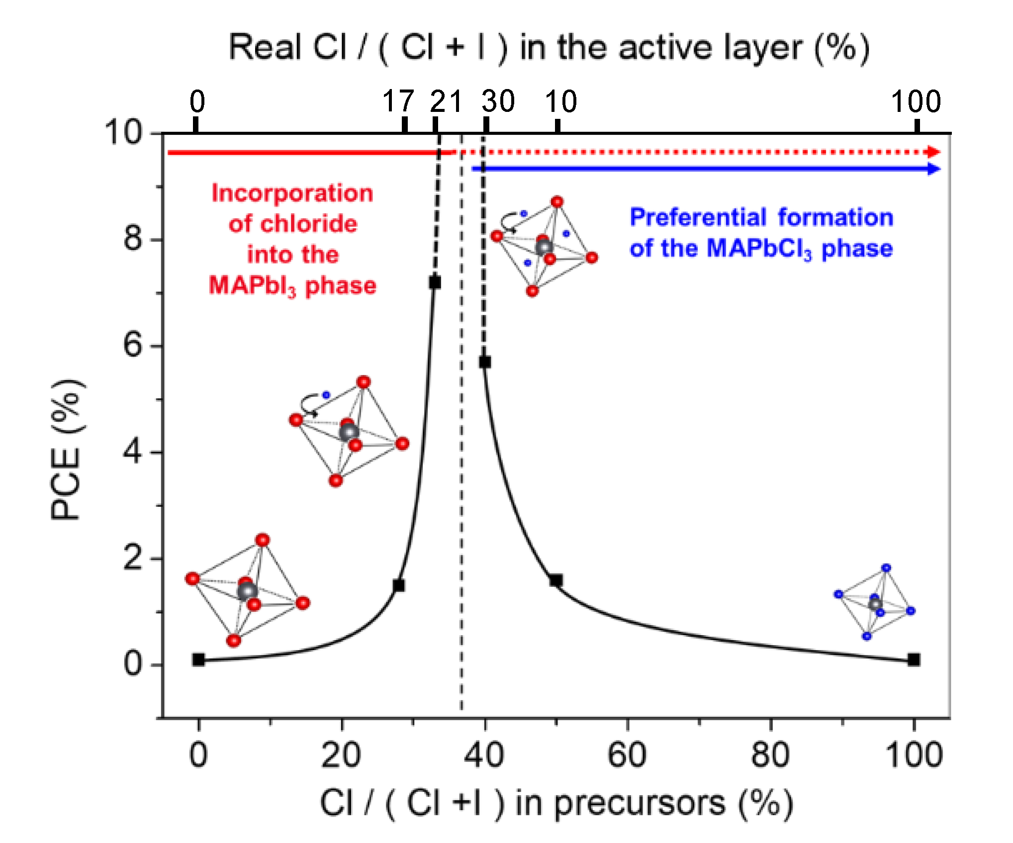
| Introduced chloride % Cl/(Cl + I) | 100% | 50% | 40% | 33% | 28% | 0% |
| Introduced MA excess (%) | 0% | 50% | 67% | 75% | 80% | 0% |
| Real chloride % (measured in the active layer) | 100% | 10% | 30% | 21% | 17% | 0% |
| Voc (mV) | Not measurable | 414 ± 45 | 951 ± 12 | 920 ± 27 | 638 ± 100 | Not measurable |
| Jsc (mA/cm2) | Not measurable | 10.9 ± 1.2 | 11 ± 2.5 | 13 ± 3 | 2.2 ± 1.7 | Not measurable |
| FF (%) | Not measurable | 35 ± 2 | 58 ± 12 | 61 ± 5 | 89 ± 35 | Not measurable |
| PCE (%) | Not measurable | 1.6 ± 0.3 | 5.7 ± 0.8 | 7.2 ± 1.5 | 1.5 ± 1.6 | Not measurable |
© 2020 by the authors. Licensee MDPI, Basel, Switzerland. This article is an open access article distributed under the terms and conditions of the Creative Commons Attribution (CC BY) license (http://creativecommons.org/licenses/by/4.0/).
Share and Cite
Spalla, M.; Perrin, L.; Planès, E.; Matheron, M.; Berson, S.; Flandin, L. Influence of Chloride/Iodide Ratio in MAPbI3-xClx Perovskite Solar Devices: Case of Low Temperature Processable AZO Sub-Layer. Energies 2020, 13, 1927. https://doi.org/10.3390/en13081927
Spalla M, Perrin L, Planès E, Matheron M, Berson S, Flandin L. Influence of Chloride/Iodide Ratio in MAPbI3-xClx Perovskite Solar Devices: Case of Low Temperature Processable AZO Sub-Layer. Energies. 2020; 13(8):1927. https://doi.org/10.3390/en13081927
Chicago/Turabian StyleSpalla, Manon, Lara Perrin, Emilie Planès, Muriel Matheron, Solenn Berson, and Lionel Flandin. 2020. "Influence of Chloride/Iodide Ratio in MAPbI3-xClx Perovskite Solar Devices: Case of Low Temperature Processable AZO Sub-Layer" Energies 13, no. 8: 1927. https://doi.org/10.3390/en13081927