A Wireless Power Transfer Based Implantable ECG Monitoring Device
by
 , , , , and
Junho Kim
1,†, 
Hyeok Kim
2,3,†,
Dongwook Kim
4,
Hun-Jun Park
2,3,5,
Kiwon Ban
6,
Seungyoung Ahn
4 and
Sung-Min Park
1,7,* 1
School of Interdisciplinary Bioscience and Bioengineering, Pohang University of Science and Technology, Pohang 37673, Korea
2
Department of Medical Life Science, College of Medicine, The Catholic University of Korea, Seoul 06591, Korea
3
Division of Cardiology, Department of Internal Medicine, Seoul St. Mary’s Hospital, The Catholic University of Korea, Seoul 06591, Korea
4
The Cho Chun Shik Graduate School for Green Transportation, Korea Advanced Institute of Science and Technology (KAIST), Dae-jeon 30580, Korea
5
Cell Death Disease Research Center, College of Medicine, The Catholic University of Korea, Seoul 06591, Korea
6
Department of Biomedical Sciences, City University of Hong Kong, Kowloon Tong 999077, Hong Kong
7
Department of Creative IT Engineering, Pohang University of Science and Technology, Pohang 37673, Korea
*
Author to whom correspondence should be addressed.
†
These authors contributed equally to this work.
Energies 2020, 13(4), 905; https://doi.org/10.3390/en13040905
Submission received: 28 January 2020
/
Revised: 14 February 2020
/
Accepted: 14 February 2020
/
Published: 18 February 2020
(This article belongs to the Special Issue Intelligent Wireless Power Transfer System and Its Application)
Abstract
:Implantable medical devices (IMDs) enable patients to monitor their health anytime and receive treatment anywhere. However, due to the limited capacity of a battery, their functionalities are restricted, and the devices may not achieve their intended potential fully. The most promising way to solve this limited capacity problem is wireless power transfer (WPT) technology. In this study, a WPT based implantable electrocardiogram (ECG) monitoring device that continuously records ECG data has been proposed, and its effectiveness is verified through an animal experiment using a rat model. Our proposed device is designed to be of size 24 × 27 × 8 mm, and it is small enough to be implanted in the rat. The device transmits data continuously using a low power Bluetooth Low Energy (BLE) communication technology. To charge the battery wirelessly, transmitting (Tx) and receiving (Rx) antennas were designed and fabricated. The animal experiment results clearly showed that our WPT system enables the device to monitor the ECG of a heart in various conditions continuously, while transmitting all ECG data in real-time.

1. Introduction
Arrhythmia, which is the disorder of the heart rhythm, is one of the most common diseases of the heart with high mortality rates and societal costs. The lifetime risks of atrial fibrillation (AF) which is a type of arrhythmia, have been estimated to be 20% in the population of 55 years and above from Rotterdam study [1]. The prevalence of AF in The U.S. is expected to increase to 12.1 million in 2030 among the general population [2]. Arrhythmia can cause symptoms such as chest pain, shortness of breath, and lightheadedness. In severe cases, it can cause complications such as stroke, cognitive impairment, dementia, and even sudden death [3]. The most common method used for detecting arrhythmia is by using an electrocardiogram (ECG). The ECG is a record of the electrical activity of the heart represented in a waveform and several features related to the cardiac cycle. Many heart diseases such as ischemic heart disease, arrhythmia, hypertrophy, and cardiomyopathies can be diagnosed by analyzing ECG waveform features [4]. However, the symptoms of arrhythmia are not continuous and appear intermittently. Thus, accurate diagnosis of AF using ECG at the specific time of monitoring would be difficult [5].
To increase the accuracy of AF diagnosis, various types of ambulatory ECG monitoring devices in the form of portable, patch, wearable, and implantable to enable continuous recording have been researched and developed [6]. Each type of those devices has different advantages and disadvantages. The portable Holter monitor can measure the most comprehensive 12 leads ECG using several electrodes for 24 to 48 h. While the Holter monitors have been used in hospitals successfully, it is difficult to use them in everyday life due to short operating time and the inconvenience of wires and gel electrodes. The wearable 1 lead patch-type devices have better usability for daily life monitoring, but they also have the disadvantage of using gel electrodes or adhesives despite being non-invasive and leadless. A wearable watch type device such as Kardiaband (AliveCor, USA) for Apple Watch has been proposed recently to enhance portability and mobility. However, those watch-type devices are only capable for on-demand measurement meaning that the ECG measurement is only performed when users initiate the measurement. The ECG measures the potential difference caused by polarization and depolarization in the heart, and thus two electrodes should be placed far from each other to increase the signal quality against noise. This implies the ECG can only be measured when the user touches the electrodes with both hands. Thus, convenience and continuity of measurement are yet to be solved by these devices.
Implantable medical devices (IMDs) have been used for many years not only for ECG measurements but also for other purposes, e.g., pacemakers, insulin pumps, and cochlear implants. The IMDs allow patients to receive appropriate treatment or diagnosis of their clinical condition anytime and anywhere. Cardiac defibrillator and cardiac pacemaker have already extended the lifespan of many people [7,8]. The research and development of new IMDs are actively being pursued to manage and treat chronic diseases such as hypertension, epilepsy, diabetes, and so on [9,10,11]. In the case of the implantable ECG monitoring device, unlike other types of ECG monitoring devices, it is less sensitive to noise and does not affect the patient’s daily life [12]. Thus, IMDs allow the patient to monitor their heart health accurately, continuously, and conveniently.
The largest drawback of implantable devices arises from the limited capacity of the battery required to run these devices continuously. Currently, most of IMDs use a primary battery that cannot be recharged. Thus, after a stipulated time, they must be replaced by surgical procedures, which are expensive, inconvenient to the patient, and prone to risks such as infection [13]. The device’s functionalities are restricted to preserve the battery power and thus limiting their potential use. Current implantable ECG monitors store or transmit the data by user activation or the detection of abnormal symptoms to conserve power. This power-saving scheme could lead to the loss of meaningful data and/or delivery of care in time. Thus, energy supply is a critical issue for IMDs.
The research on energy harvesting and wireless power transfer (WPT) for medical device application is being actively pursued to find a way to replace or recharge a battery [14,15]. Typical energy harvesting techniques using thermal energy or vibration in the human body get only tens of uW of energy, which is not sufficient for IMDs that need chargeability to support continuous recording and transmitting data to outside the body [16]. The WPT, on the other hand, can provide few mW of energy and thus may be a better solution for IMDs with the continuous data record and communication need. A variety of WPT methods including inductive coupling, acoustic power transfer (APT), and electromagnetic mid-field have been recently studied for IMDs [17,18,19]. Inductive coupling using two coils is a common technique for WPT and this method can transfer high power in near field. Power transfer efficiency varies depending on the design of coils and the distance between them and research has been conducted to improve their efficiency [20,21,22]. Unlike the inductive coupling, the APT uses sound waves to transfer energy. It has high penetration depths, but the applicable device implantation location is limited since the difference in medium, such as different organs, have different acoustic impedances affecting the efficiency [23]. Metal patterning has also been studied to use propagating fields in the electromagnetic mid-field regime for transferring power to the deeper tissue than conventional electromagnetic power transfer methods [24]. However, this method is also limited for the amount energy to be transferred and thus is not suitable for charging purpose. In this context, we applied inductive coupling to our proposed implantable ECG device to support recharging function that enables continuous data record and transmission to outside the body. In this paper, we proposed an implantable ECG monitoring device based on WPT that can measure and transmit ECG 24 h a day. As a first step towards implantable medical devices in humans, we developed and tested our implantable ECG monitoring device in an animal to confirm the applicability of WPT to IMDs. Many research groups have measured ECG by attaching electrodes and connecting wires to the outside of anesthetized rats [25,26]. The implantable ECG monitoring device allows conducting experiments in a natural state of the animal without anesthesia. In addition, since it is impossible to predict when arrhythmia will occur, and the duration of arrhythmias varies from seconds to minutes, continuously monitor ECG is essential. In the following sections, the design and manufacturing process of the ECG monitoring device with WPT is described along with the animal experimental results.
2. ECG Monitoring System
2.1. The Principle of Electrocardiogram (ECG)
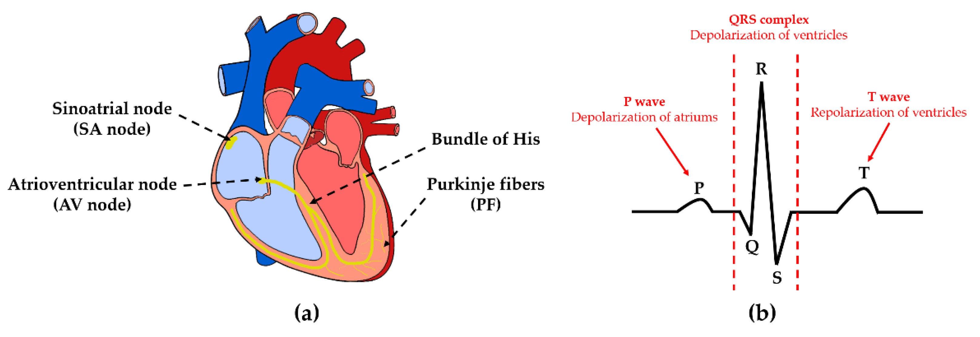
This section briefly summarizes the basic principles of ECG for completeness. More details about ECG can be found in [27]. The heart continuously contracts and relaxes rhythmically, circulating blood throughout the body. The sinoatrial node (SA node), located in the wall of the right atrium, spontaneously generates electrical signals, responsible for the heart’s rhythmic motion. These electrical signals flow throughout the heart along atrioventricular node (AV node), the bundle of His, and Purkinje fibers (PF), sequentially causing contraction and relaxation in the heart muscle (Figure 1a). The recording of this heart’s electrical activity is the ECG. There are feature points called P, Q, R, S, and T on the ECG, and each of them reflects the steps of the cardiac cycle (Figure 1b). Thus, using ECG wave analysis, heart conditions related to heart rate (HR) can be diagnosed. ECG can be recorded using two electrodes by measuring the voltage difference between them. The measured voltage needs amplification since the difference in voltage is very small.
2.2. System Configuration
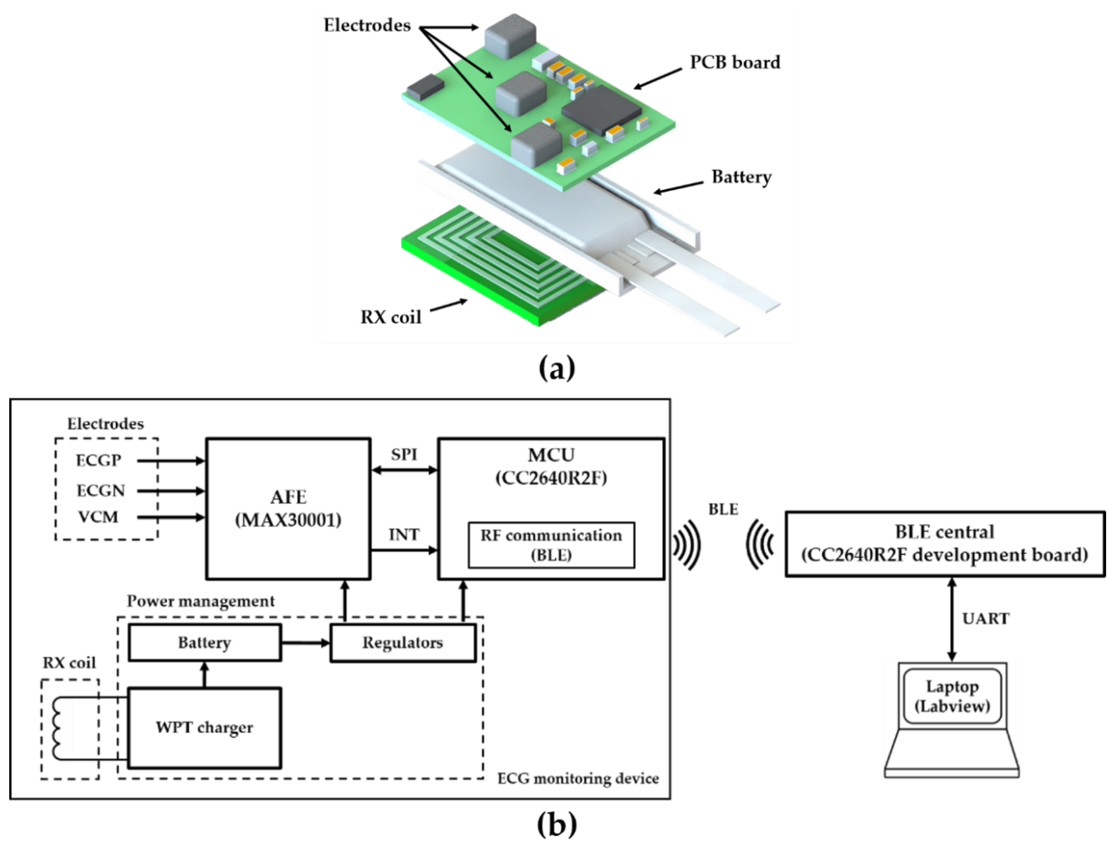
The 3D model and system configuration of the proposed ECG monitoring device are shown in Figure 2. It consists of a printed circuit board (PCB), a battery, and a receiving (Rx) coil for WPT. The process of obtaining ECG data using this system is described as follows: Three electrodes are connected individually to ECGP, ECGN, and VCM pins of an analog front-end (AFE) chip. ECGP and ECGN are positive and negative pins, respectively, and VCM is a common-mode pin. The voltage difference between ECGP and ECGN pins is digitized into 18-bit digital data in AFE chip via the amplifier, filter, and analog-to-digital converter (ADC). The sampling rate in the AFE can be selected between 128, 256, and 512 Hz. The VCM pin is used as a body bias to drive the body to the common-mode voltage. The AFE chip can store data up to 32 samples, and once the samples are collected up to the set number, it sets the INTB pin of the AFE low to send the signal to the microcontroller unit (MCU). Whenever the INTB pin goes low, the MCU reads data from the AFE through serial peripheral interface (SPI) communication. The MCU stores MSB 16-bit data of 18-bit ECG data and transmits Bluetooth Low Energy (BLE) whenever 96 data (192 bytes) are collected. After receiving the data, the BLE host transmits them via universal asynchronous receiver/transmitter (UART) to a laptop computer which uses LabVIEW to visualize ECG signal, send commands, and store data.
2.3. ECG Monitoring Device Design and Specification
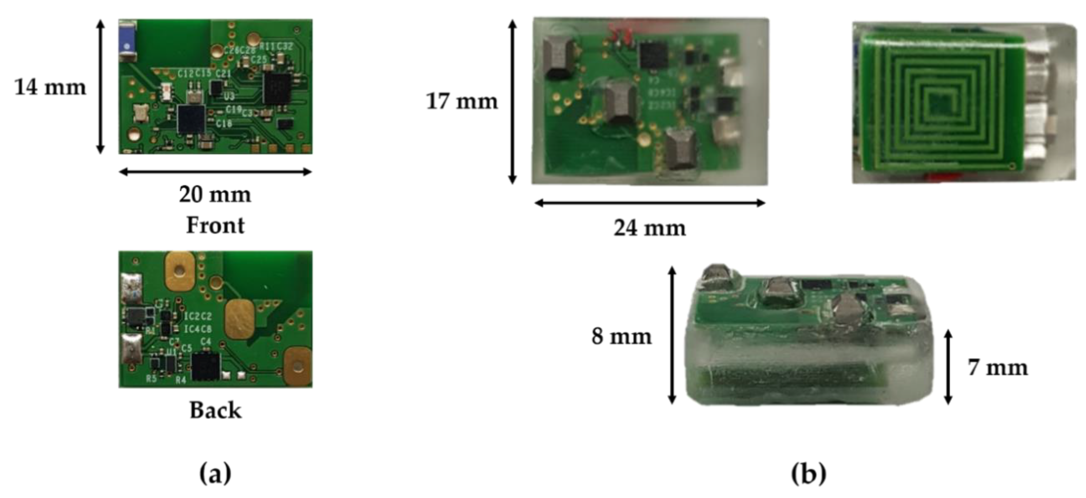
A thin and small commercial lithium-ion polymer battery was used for the purpose of device miniaturization. A pouch-type rechargeable battery, FLPB301220 (Routejade, South Korea), of size 20 × 12 × 3 mm with 48 mAh capacity was used for supplying power to the ECG monitoring device. The main board of the ECG monitoring device is shown in Figure 3a. It is of size 20 × 14 x 0.6 mm and made of 4-layer of PCB using FR-4 material to accommodate the battery. The PCB was designed with PCB editor in OrCAD 17.2 (Cadence, USA). Electrodes are made of stainless steel in the shape of a rectangular prism of size 4 × 3 × 2 mm. The top surface of the electrodes is chamfered by 1 mm to prevent injury after implantation. The electrodes are physically and electrically connected with the PCB using silver conductive epoxy adhesive. The MCU is CC2640R2F (Texas Instruments, USA). It contains an ARM cortex-M3 CPU, an RF core for BLE communication, and peripherals such as ADC, UART, SPI, and general-purpose input/output (GPIO). The package size is small, which is a 2.7 × 2.7 mm, 34-pin die-size ball grid array (DSBGA). The integrated circuit (IC) chip used as the AFE is MAX30001 (Maxim integrated, USA). It is a single biopotential channel providing ECG waveforms that has ultra-low-power, low noise, programmable gain, high-resolution ADC, with various filter options. The XCM414 (Torex semiconductor, Japan) is an IC for WPT, which includes four Schottky barrier diodes and a voltage regulator. Battery protection circuit and charging circuit protect overcharge, over-discharge, and overcurrent. Since we used a 48 mAh battery, charging current is limited to about 44 mA to maintain battery life. The voltage of the battery and the charging current by WPT are measured using ADC and a current sense amplifier. The battery and the PCB are connected by soldering, while Rx coil and PCB are connected using a wire. The ECG monitoring device was covered using biocompatible epoxy, EPO-TEK 301 (Epoxy Technology, USA), except at the top of the electrodes. The actual picture of the complete fabricated device is shown in Figure 3b. The size of the whole device is 24 × 17 × 8 mm. The mold for covering epoxy was made using a 3D printer printout, which is of the same size as the device and duplication silicone.
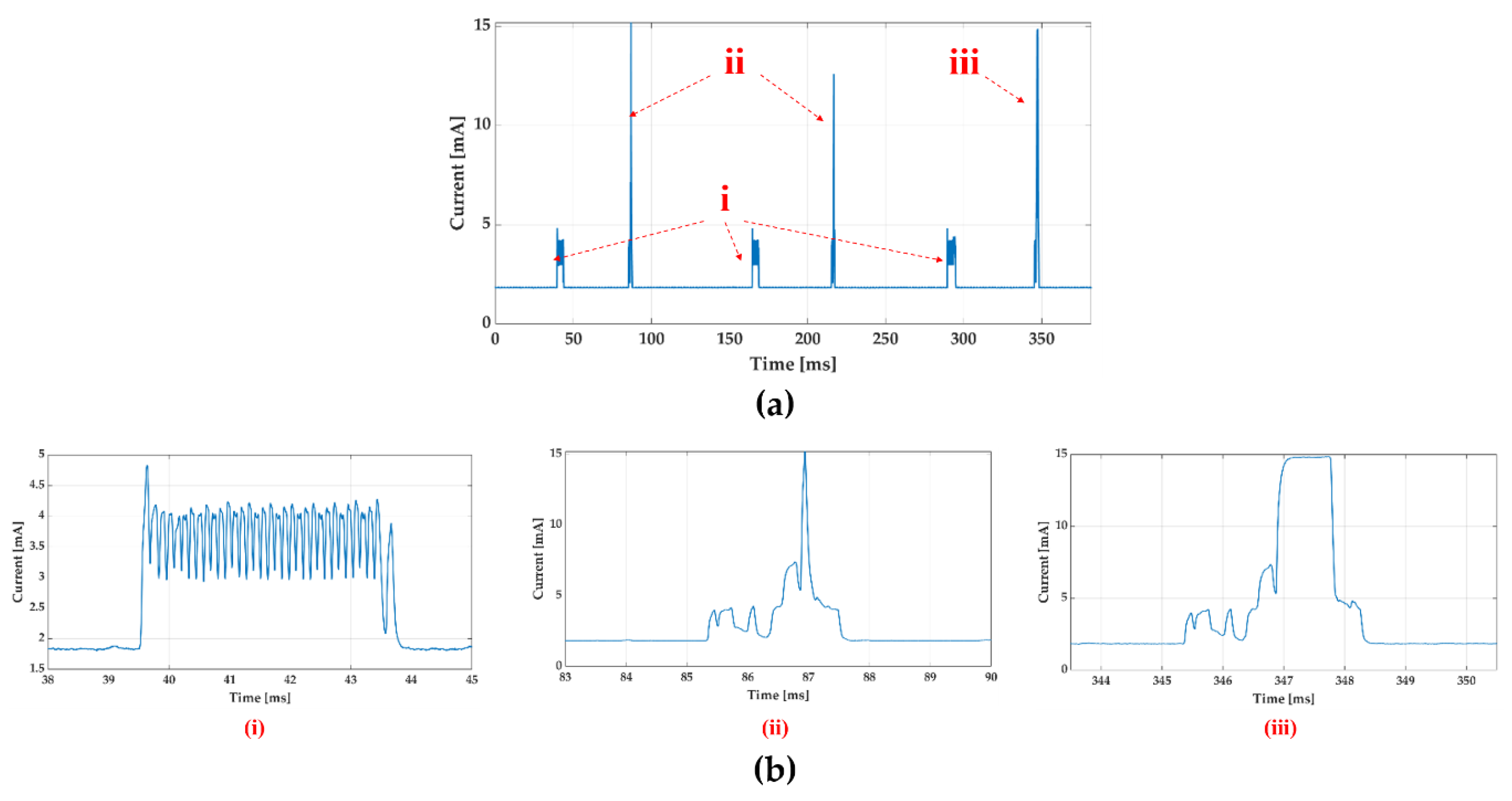
The current consumption was measured by connecting a 10-ohm resistor to the battery and measuring the voltage difference across the resistor. Figure 4 shows the current consumption calculated from the measured voltage with the ECG monitoring device working. The four operating states belonging to one cycle of device operation as shown in Figure 4a are; (1) idle state, (2) data acquisition from AFE, (3) BLE connection event, and (4) connection event with data transmission. In idle state, AFE collects ECG data and MCU waits for interrupt signal from AFE. When 32 samples are collected in AFE, AFE sends the signal to the MCU and the MCU reads data from AFE through SPI communication (Figure 4a(i)). The connection events between a BLE host (data receiver) and BLE peripheral (ECG monitoring device) in our application occur every 130 ms (Figure 4a(ii)). After 96 data are collected in the MCU, the collected data is sent to the next connection event (Figure 4a(iii)). In the idle state, the current consumption is about 1.84 mA. By integrating the area under the curve for current (Figure 4a), we can see that the average current consumption is 1.97 mA for one cycle. This implies, with a 48 mAh battery, the ECG monitoring device can run ideally for about 24.3 h with a charge of 1 h per day.
3. Wireless Power Transfer (WPT) System
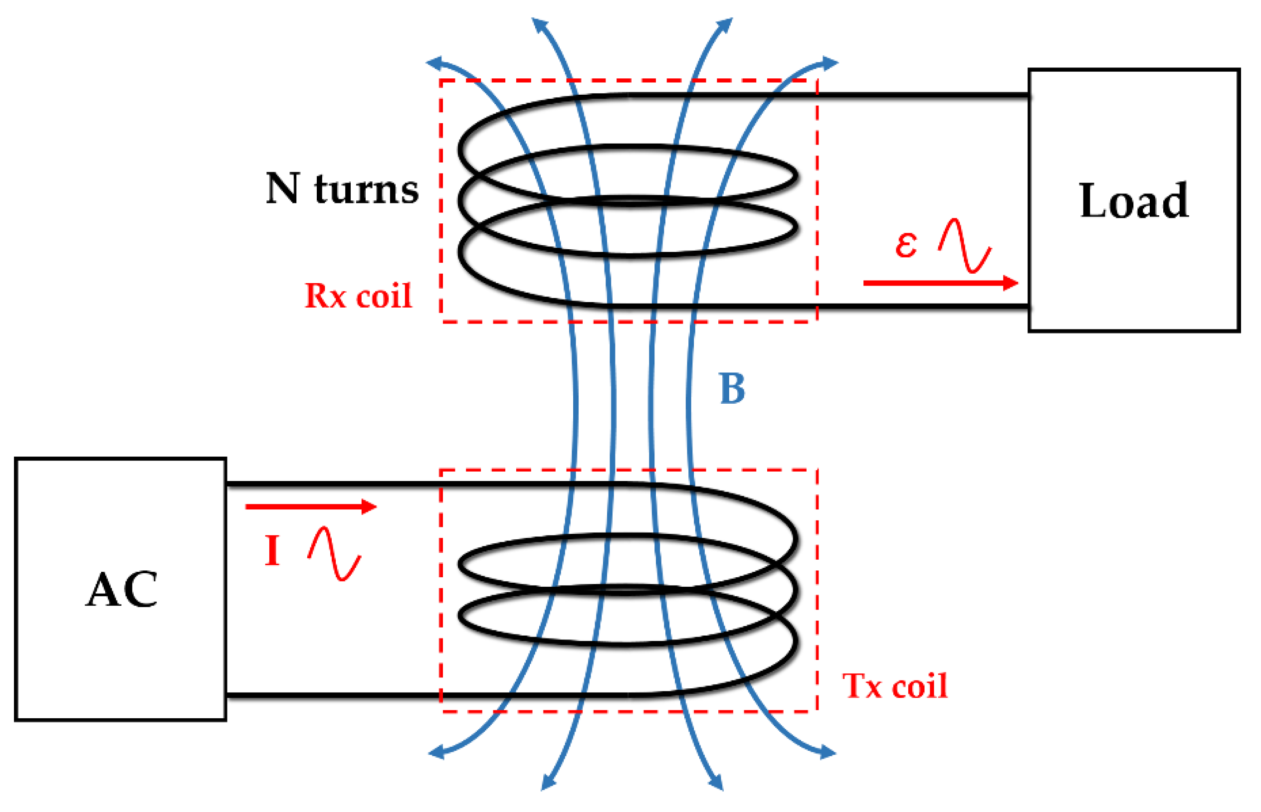
The operation frequency of the proposed WPT system is 6.78 MHz, which corresponds to industrial, scientific, and medical (ISM) radio band. The basic principle of the WPT system is Faraday’s law. Figure 5 shows the principle of magnetic induction in WPT. When the AC current flows in the transmitting coil (Tx), a time-varying magnetic field is generated. When this magnetic field passes through the receiver coil (Rx), a voltage is induced at the end of the coil. The induced voltage is expressed using Equation (1).
where ε is an induced electromotive force, N is the number of coil turns, is the magnetic flux, B is the magnetic field, and A is the area of the coil.
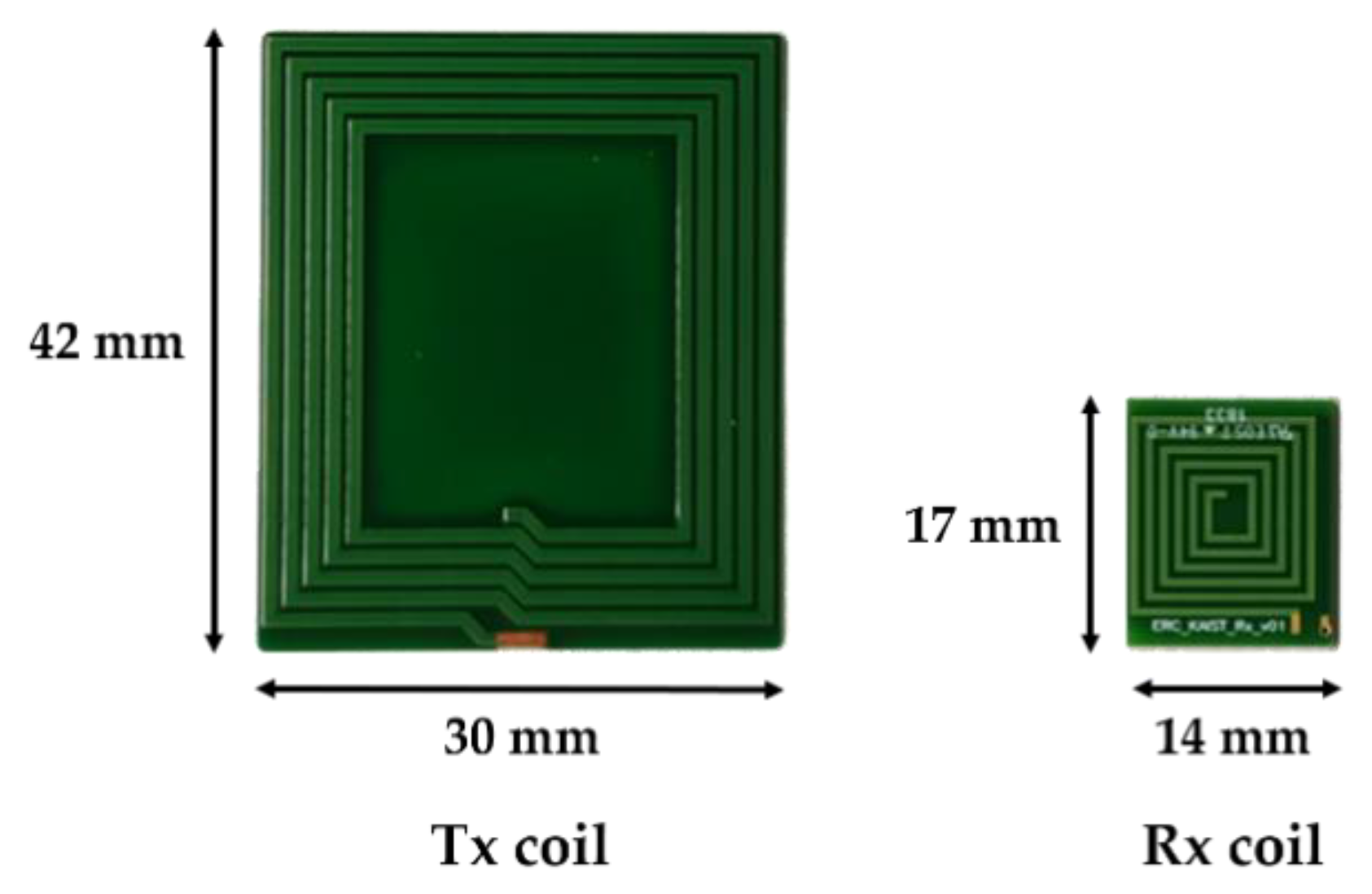
According to Faraday’s law, the larger the N, the higher the induced voltage and the coupling coefficient. The Rx coil was designed considering the size of the mainboard and the battery, so it was designed to maximize the number of coil turns in a limited space. The Rx coil was manufactured in 6-layers and 6 turns per layer with traces of 0.5 mm width and 0.07 mm thickness within a 17 × 14 × 1 mm space (Figure 6). We added ferrite sheets of 0.6 mm thickness between the Rx coil and a battery to magnetically isolate them. Since the battery is covered with metal and attached to the Rx coil, the magnetic field induced by the eddy current in the metal reduces the efficiency of the WPT. The thicker the ferrites sheets, the better the isolation effect. The thickness of the ferrite sheets was set to 0.6 mm, considering the thickness of the device. Ferrite is a noxious material, thus packaging with a biocompatible material such as epoxy is essential. The Tx coil has no size restriction unlike the Rx coil. Considering the usability in the animal experiment, the size of the Tx coil was set to 4 times larger, taking into misalignment consideration. The Tx coil for energy transfer was made of 42 × 30 × 0.5 mm size. It was made of a 2-layers PCB with 5 turns per layer. The line width of the Tx coil was 1.0 mm. Any additional turns would decrease the self-resonance frequency (SRF) and increase the effective series resistance (ESR), thus making it unsuitable for use as a WPT antenna at our target frequency of 6.78 MHz [28].
In the case of loosely coupled coils, the compensation capacitor is crucial for maximizing the efficiency of the WPT system [29]. There are four basic compensation topologies for WPT system: series-series (SS), series-parallel (SP), parallel-series (PS) and parallel-parallel (PP) [30,31]. When the frequency of the source is equal to the resonant frequency of Tx coil, the current flowing through the Tx coil is largest and it makes the largest time-varying magnetic field. To maximize the induced voltage in the Rx coil, the capacitor should be connected in parallel for the largest impedance. If the primary voltage remains constant, the SP topology acts as the source for constant voltage [32]. We used SP topology to simplify the battery management system. Since SP is more efficient than SS when the Tx coil is bigger than Rx, series capacitor (Cs) and parallel capacitor (Cp) were connected to the Tx and Rx coil, respectively [33]. The values of primary and secondary capacitors are calculated using Equation (2).
where is a resonance frequency, and L1 and L2 are the inductance of Tx and Rx coil, respectively.
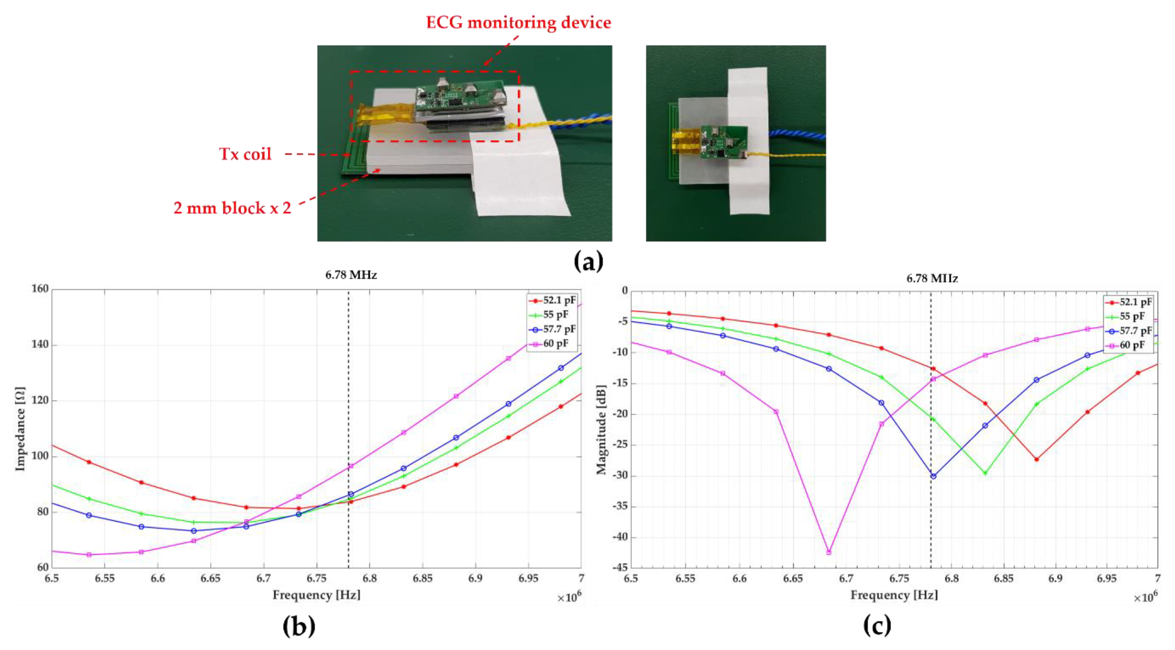
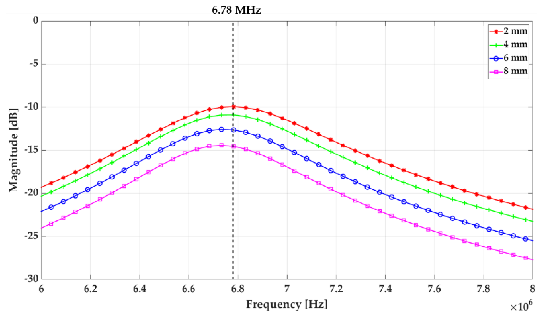
The inductance of the Tx coil and Rx coil are 10.91 uH and 1.95 uH respectively at 6.78 MHz. From Equation (2), the value of Cp was calculated to be 282.58 pF. Thus a 270 pF ceramic capacitor was used. The theoretical value of Cs was 50.51 pF, which implies the impedance of the Tx side was the smallest. However, when considering the whole charging system, not only impedance but also S parameter should be considered. Figure 7 shows the measurement setup of the S and Z parameter and their result. The mainboard, a battery, and Rx coil were placed together similar to the ECG monitoring device, and the coil spacing was maintained at 4 mm, considering the animal testing conditions (Figure 7a). To avoid overvoltage on the capacitors, four capacitors were connected in series to reduce the voltage load on each capacitor. Three capacitors are fixed to 220 pF. The parameters were measured by changing the value of the fourth capacitor to 180, 220, 270, and 330 pF. The total capacitance in each case was 52.1, 55, 57.7, and 60 pF, respectively. As an optimization process for the whole power transfer system, both impedance and reflection need to be minimized by achieving smaller Z11 and S11 while varying capacitors in the system. As shown in Figure 7b, c, the dependence of Z11 at the operation frequency on the total capacitance was less than S11. Therefore, in consideration of the overall system efficiency, the value of Cs was set to 57.7 pF that achieved the smallest S11 at 6.78 MHz. In addition, the distance between the Tx and Rx coils is a major influencer for the power transfer efficiency. Figure 8 shows the power transmission efficiency, S21 as a function of the distance between the Tx and Rx coils. In the inductive charging method, it is well known that the power transfer efficiency decreases rapidly as the distance between the two coils increases, and the result of S21 measurement also showed the same trend. This result means that the nearer the Tx coil to the Rx coil is better for the power transfer. However, the Tx coil location would be determined considering the potential skin safety (e.g., Tx coil touching the skin may generate the skin burn) while Rx coil is fixed during the implantation in real-world application. Therefore, we built the custom fixture to keep the distance between the Tx and Rx coils constant while preventing direct contact of the Tx coil to the skin.
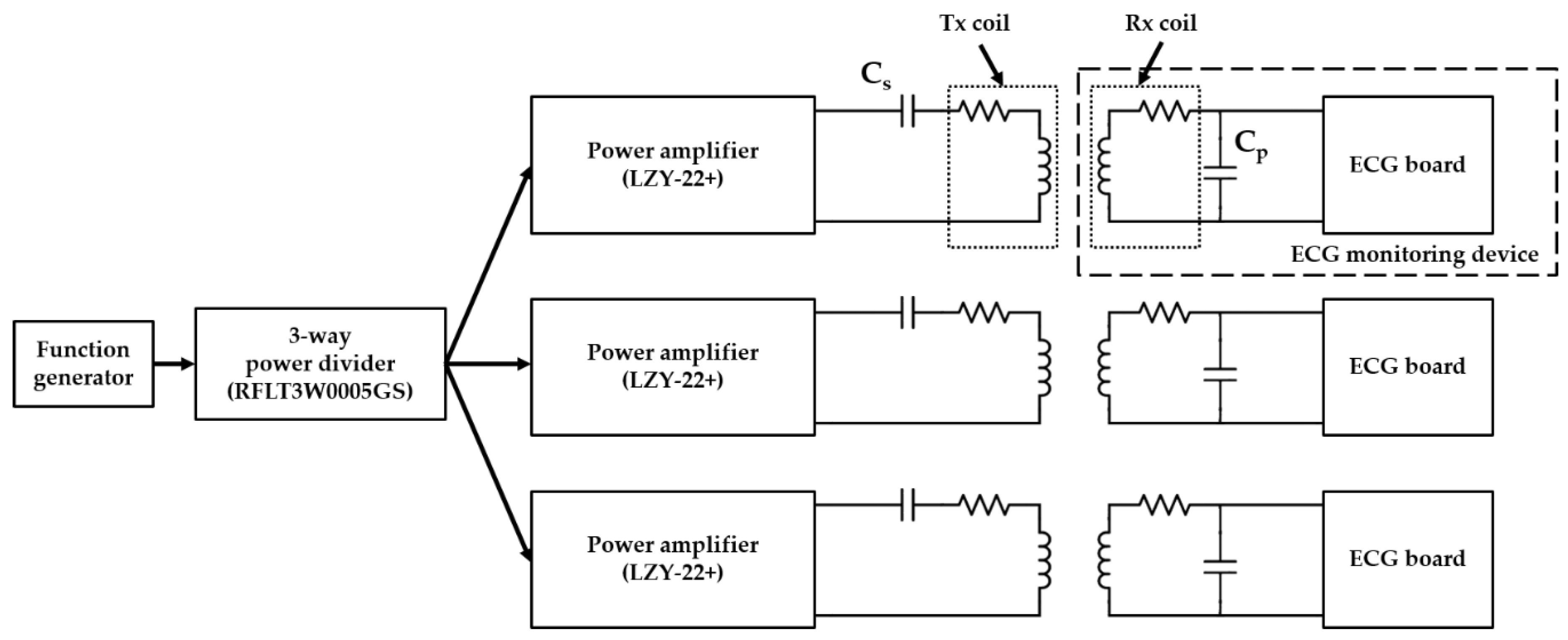
The charging platform with multiple WPT system was configured and is shown in Figure 9 for charging multiple devices for animal experiments. The 6.78 MHz sine wave required for WPT was generated using a function generator. The 6.78 MHz sine wave was divided into three signals by a 3-way power divider, RFLT3W0005GS (RF-LAMBDA, USA), which can handle up to 10 W, and 1–500 MHz wideband frequency signals. Each divided signal was amplified by a power amplifier, LZY-22+ (Mini-Circuits, USA) with 43 dB gain and 50-ohm output impedance.
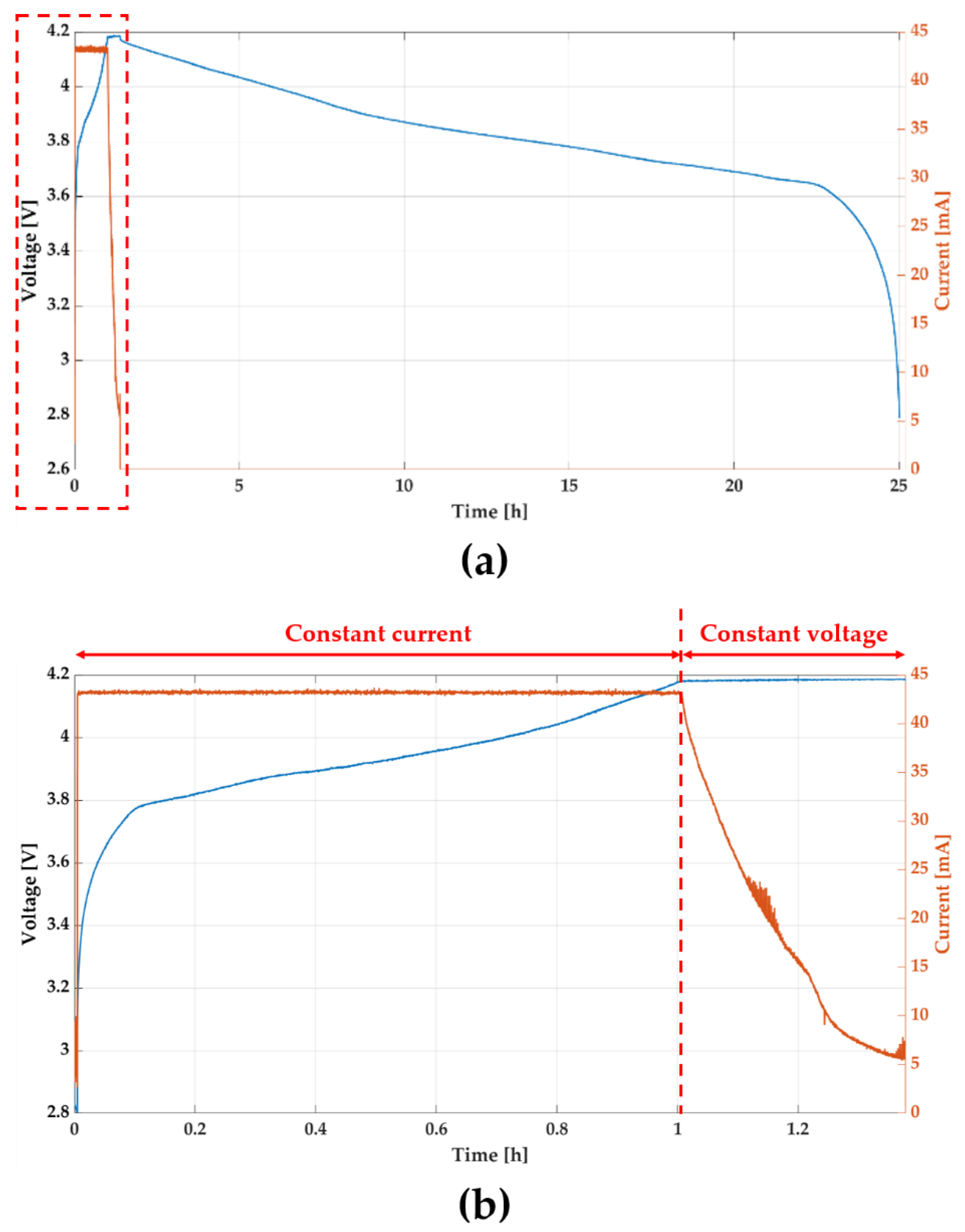
An experiment was conducted to verify the charging and operating time of the device, and the operation of the charging system. The battery voltage and charging current from the start of the charge to the end of device operation is shown in Figure 10. Figure 10b is an enlarged view of the red box in Figure 10a showing the battery voltage and charging current during charging. At first, the battery was charged to about 43 mA in constant current mode. Since the protection circuit limits charging current, the current did not increase even if the voltage of the function generator increased. The minimum input power of Tx coil was about 1.8 W for maintaining maximum charging current. Charging voltage and current were 4.2 V and 43 mA, thus power transfer efficiency was about 10% in terms of whole system. Once the charging voltage reached to about 4.2 V, which is the maximum voltage of the battery, charging current began to decrease. As shown in Figure 9a, the device operated for 23.6 h after charging for 1.4 h.
4. In Vivo Experiment
To verify device operation and WPT system, we conducted an in vivo experiment for five days using a rat model. At first, we measured normal ECG from all rats after implanting our device. The normal ECG serves as the baseline for all animals. Then, myocardial infarction (MI) was surgically induced and MI ECG was measured. Both MI and control group received drug injections and showed significant changes in heart rate caused by drugs. The experimental procedures are described in details as follows.
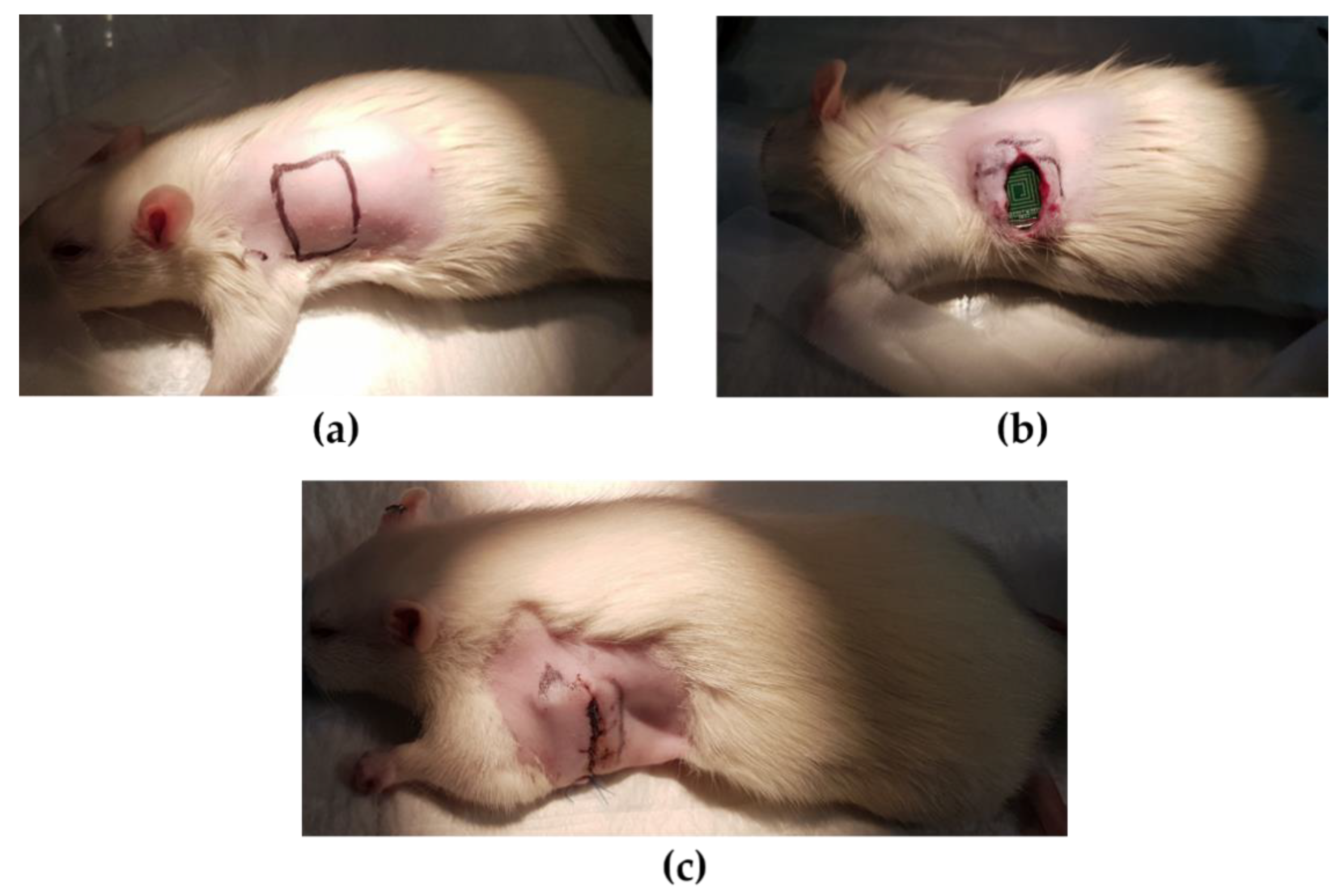
The animal experiment was approved by the Catholic University of Korea Animal Care and Use Committee and IACUC (CUMC-2019–0058–01). Eight Fischer 344 rats (180–200 g, 8-weeks old male, Koatech, Korea) were anesthetized with 2% inhaled isoflurane and intubated via the trachea with an 18-gauge intravenous catheter. The rats were then mechanically ventilated with medical-grade oxygen. The body temperature of animals was maintained at 37℃ by placing on a heating pad to prevent cooling during the procedure. After shaving the left dorsolateral site, the location where the device would be placed was incised 2 cm vertically (Figure 11a). The skin around the incision was dissected from underlying connective tissue to form a pocket to place the device. The device was inserted and sutured with 4–0 prolene as shown in Figure 11b,c. The recovered rats were transferred to a cage and the ECG was collected for 24 h by real-time monitoring. The device was small enough for rats to live normally after the implantation, and the rats recovered from the incision very quickly.
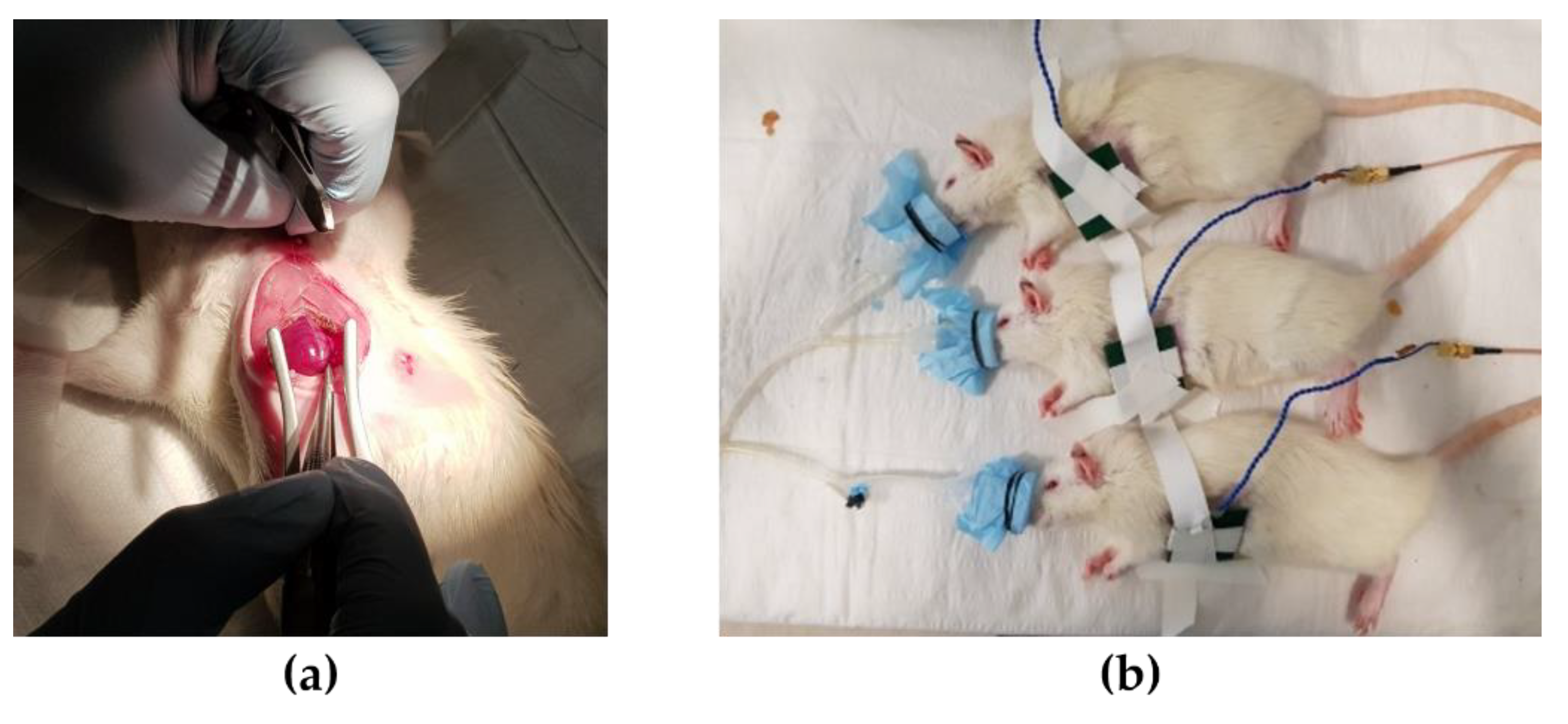
While conducting animal experiments, it is necessary to not only measure normal ECG but also ECG under various heart conditions. To induce abnormal heart conditions, drugs were used to induce tachycardia and bradycardia, and surgery was performed to induce MI. The rats were randomly divided into two groups of 4 rats each, namely, the device implantation without MI and the device implantation with MI. The MI group (n = 4) was anesthetized and intubated using the same process of the device implantation previously described. The chest was shaved and a left thoracotomy was performed. The MI was induced in each rat by permanently ligating the left anterior descending (LAD) artery using a 7–0 prolene (Figure 12a). The MI induced animals recovered from surgery within 30 min of post-surgery in the oxygen chamber. The rats were anesthetized with a nasal cone and the implanted device was charged wirelessly for 1 h daily. A 2 mm thick block was placed on the site where the device was implanted with the Tx coil fixed on it during charging (Figure 12b). Since the anesthesia system allowed up to three rats to be anesthetized at the same time, we conducted an experiment with three rats simultaneously. To avoid infection, all animals received intraperitoneal injections of antibiotics (Cefazoline, 50 mg/mL, 500 ul) every two days. Except for charging time, drug injection and MI induce surgery, rats were left in cages in a natural state.
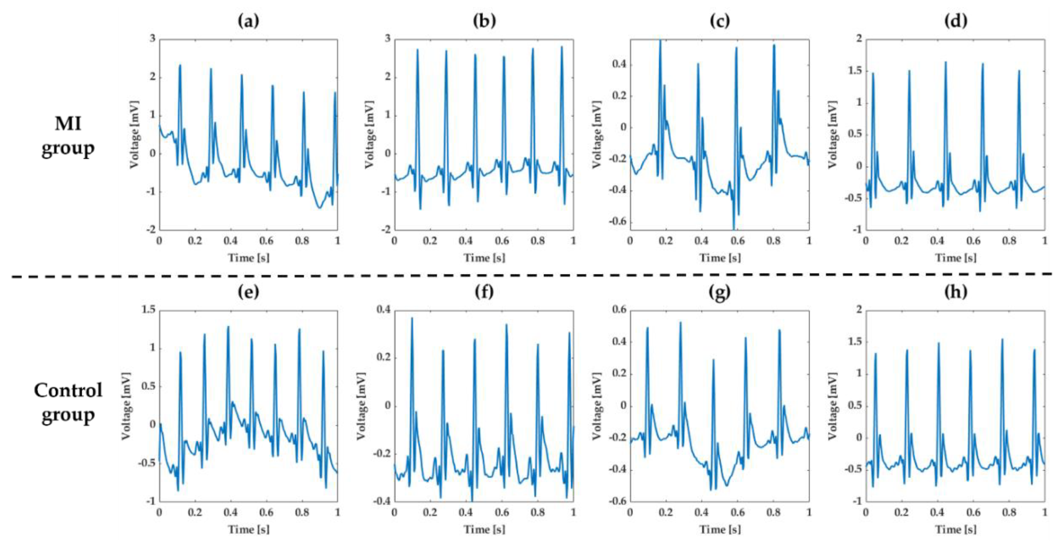
The normal ECG waveforms measured after implanting ECG monitoring devices are shown in Figure 13. In Figure 13a–d the ECG waveforms are shown of the MI group, and in Figure 13e–h the ECG waveforms of the control group are shown. The rat’s normal HR is 330 to 380 beats per minute (BPM), which is faster than the human’s normal HR of 60 to 100 BPM. The sampling rate of 256 Hz in our device was sufficient to measure the ECG waveform of the rat. Even though the waveform differed slightly depending on the rats and the position of the devices, the normal rats showed normal characteristic features of rat ECG using our device [34,35].
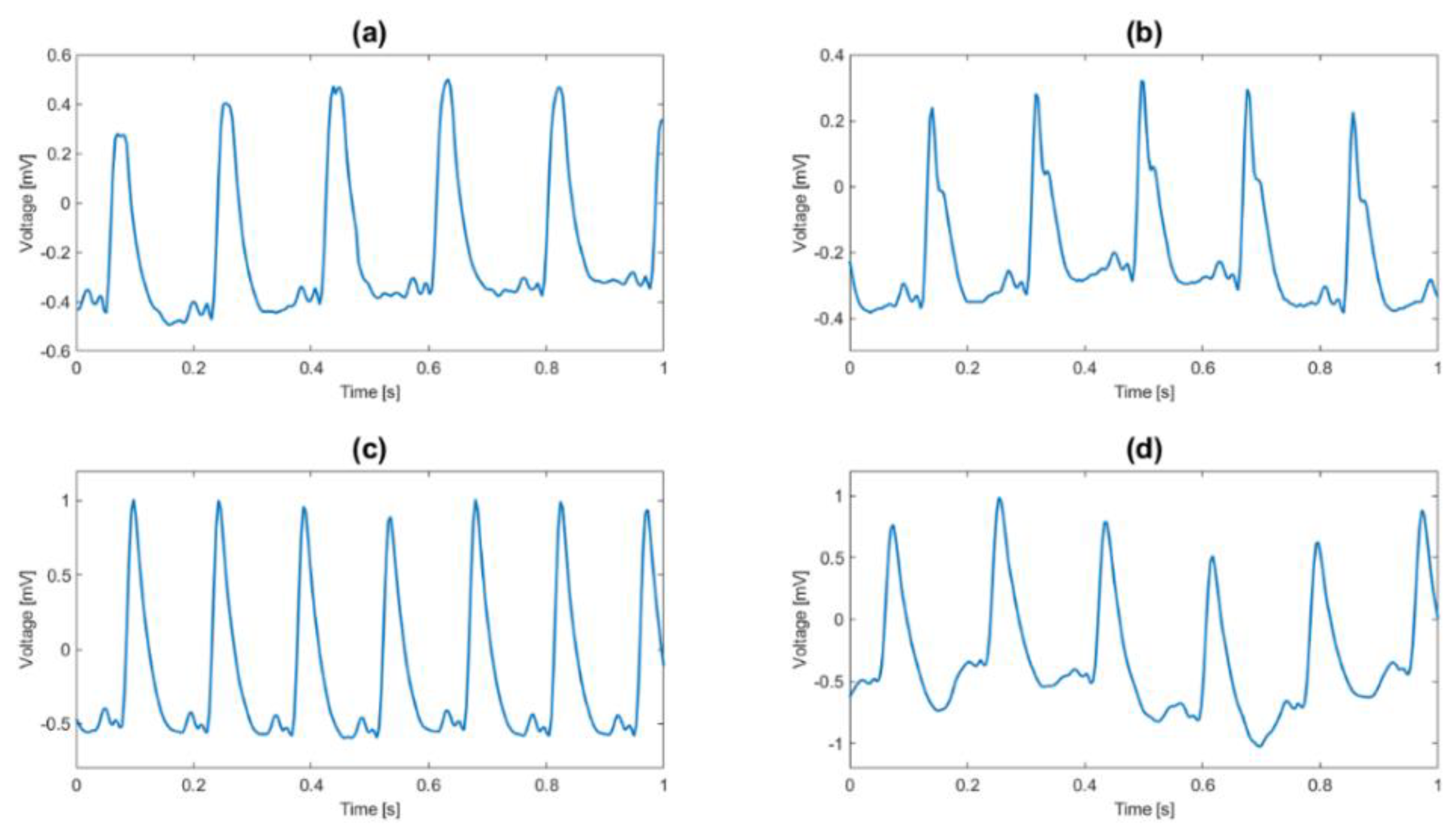
The ECG waveforms of the MI group after inducing MI are shown in Figure 14. The ECG waveforms of MI group were completely different compared to the normal ECG. The ST segment of ECG, shown in Figure 14, was noticeably elevated, suggesting that MI was successfully induced [36,37,38] and MI can be diagnosed with our device.
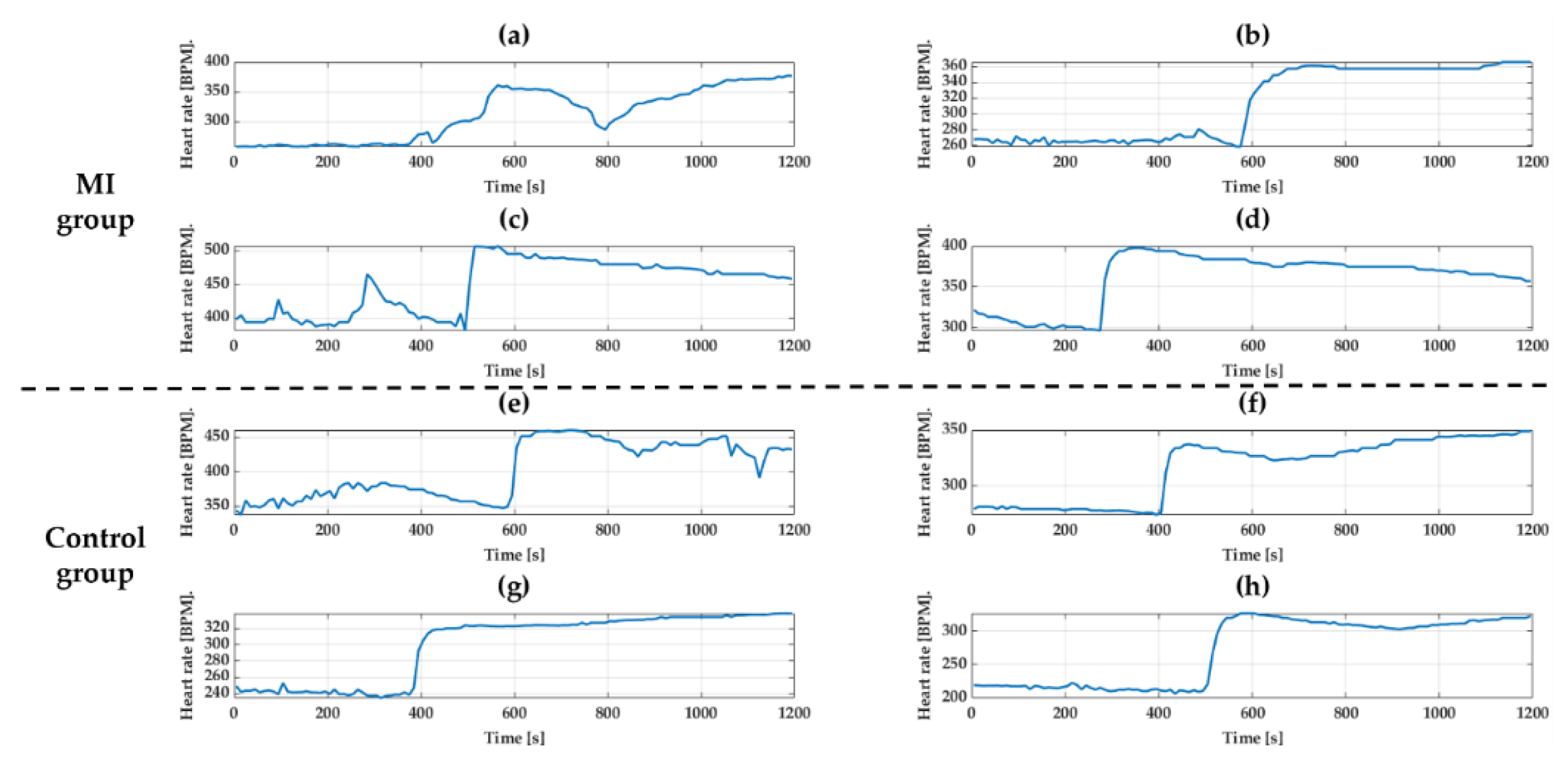
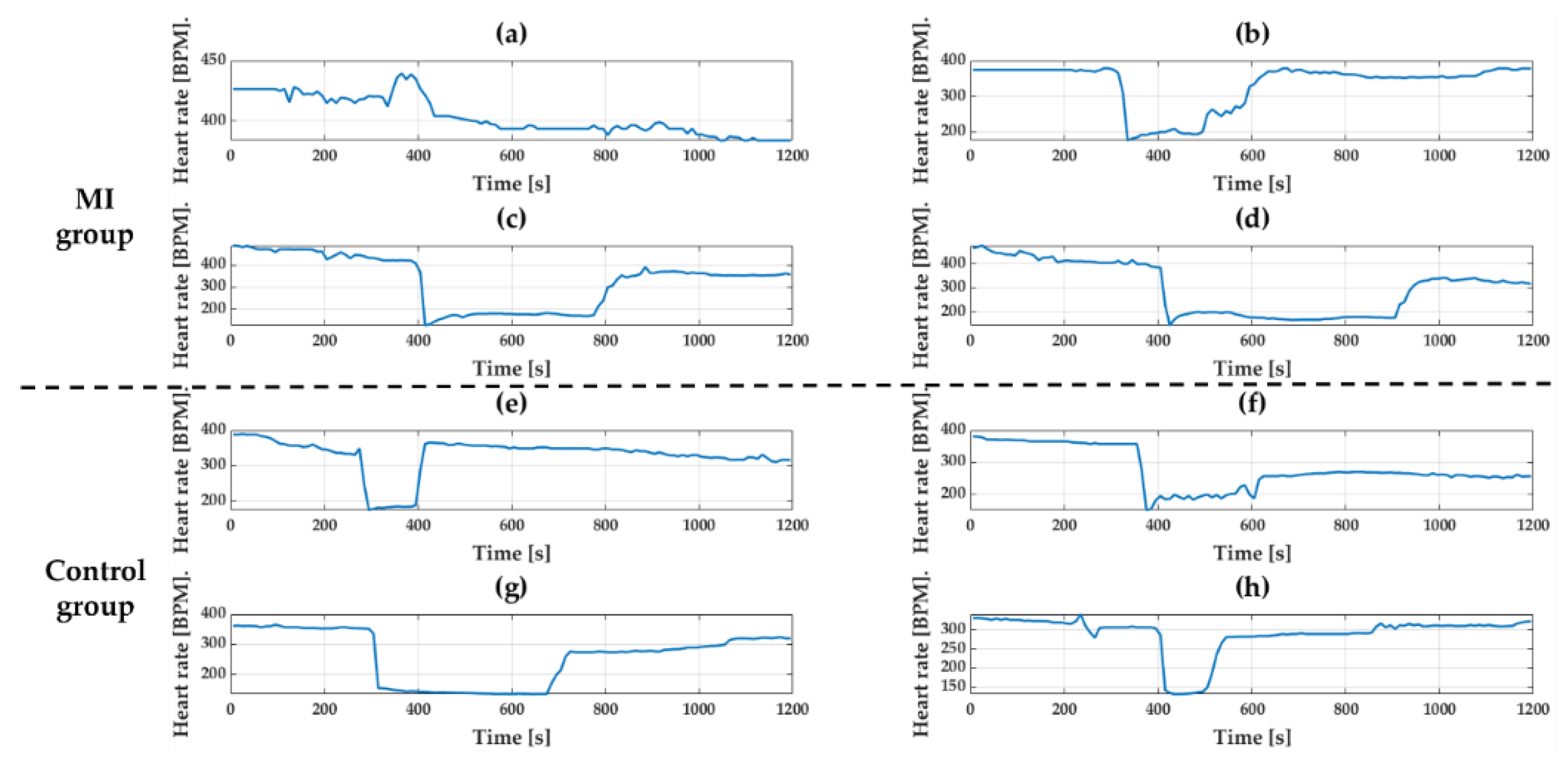
Isoproterenol (30 ug/kg, 300 ul) and Diltiazem (10 mg/kg, 300 ul) were used to make change in HR. Both groups were anesthetized first and drugs were injected into the tail vein to induce tachycardia and bradycardia. There was no change in ECG waveform before and after injecting the drugs, but only the change was in the length of waveforms. To see the response of drugs, HR was calculated using the interval of the R peak and was averaged over 10 s. Figure 15 and Figure 16 show the change in HR for 20 min after drug injection. As expected, both tachycardia and bradycardia agents successfully induced the fast and slow HR’s, respectively. However, it should be noted that one rat with results shown in (a) in both Figure 15 and Figure 16 showed different responses than other animals. This may not come from the device failure but peculiarity in that animal. For example, due to difficulty in finding the vein of that animal, the tachycardia agents had to be injected twice. Therefore, we believe that the difference in the response was due to the animal difference, not the device. The biggest change after Isoproterenol injection was shown in Figure 15h where the heart rate changed from 213 BPM to 327 BPM. In the case of Diltiazem, the efficacy of the drug was short, and the HR returned to normal very quickly. The response to the drug was similar in both groups regardless of MI.
5. Conclusions
In this paper, we presented a WPT based implantable ECG monitoring device. The device we developed is of size 24 × 17 × 8 mm, which is small enough to be implanted in humans. We demonstrated the feasibility of this device to monitor ECG continuously in rats. The device can acquire ECG data at 256 Hz sampling rate with 16-bit high resolution, which is sufficient to meet clinical criteria. The Tx and Rx coils were designed considering the clinical usability and size of the ECG monitoring device. The device can obtain and transmit ECG data continuously for over 23 h without recharging a battery. The SP compensation topology used enables to develop a simple but efficient WPT system and a charging platform for multiple WPT system. After implanting the device into a rat, the operation of the device was able to be maintained using WPT. These operational findings and unique compact design show the possibility of deploying this device clinically in the near future.
While performing the experiment we came across three limitations of the devices, which need to be improved further as stated below:
- The ECG waveforms vary depending on the position of the device due to the difference in electrodes position. Thus, by securing the device with a biocompatible adhesive inside the body, the repeatability of the ECG waveforms can be improved.
- The WPT lends itself to electromagnetic interference (EMI). The biopotential is small and therefore vulnerable to noise such as 60 Hz from the power line. Thus, while using the WPT, the ECG was not measured appropriately. To solve this problem, EMI shielding needs to be added to the electrodes.
- Finally, even slight misalignment between Rx and Tx coils has an impact on the efficiency of WPT. Thus, the care should be taken in fixing the Tx coil.
In spite of improvement needed to the device, the animal experiment result showed that the current device can acquire ECG data continuously under various cardiac conditions, such as tachycardia, bradycardia, and MI, and can transmit ECG data continuously using WPT. Here we showed the feasibility of the ECG monitoring device as an application of IMDs using WPT and proved its effectiveness through in vivo experiment. In conclusion, we showed that the application of WPT could enhance the functionality of IMDs.
Author Contributions
S.-M.P. and S.A. proposed concept of the device; S.-M.P., H.-J.P., K.B., J.K., and H.K. planned the experiments; J.K. designed and developed the device; J.K. and H.K. carried out the animal experiments; D.K. designed coils. All authors provided critical feedback, analyzed the data, and wrote the paper. All authors have read and agreed to the published version of the manuscript.
Funding
This research was supported by the National Research Foundation of Korea (NRF) grant funded by the Korea government (MSIT) (NRF-2017R1A5A1015596), the Korea Health Technology R&D Project through the Korea Health Industry Development Institute (KHIDI) funded by the Ministry of Health & Welfare, Republic of Korea [grant number: HI17C1314], and the Technology Innovation Program (or Industrial Strategic Technology Development Program) (20001841, Development of System for Intelligent ContextAware Wearable Service based on Machine Learning) funded by the Ministry of Trade, Industry & Energy (MOTIE, Korea).
Conflicts of Interest
The authors declare no conflicts of interest.
References
- Heeringa, J.; van der Kuip, D.A.; Hofman, A.; Kors, J.A.; van Herpen, G.; Stricker, B.H.; Stijnen, T.; Lip, G.Y.; Witteman, J.C. Prevalence, incidence and lifetime risk of atrial fibrillation: The Rotterdam study. Eur. Heart. J. 2006, 27, 949–953. [Google Scholar] [CrossRef] [PubMed] [Green Version]
- Colilla, S.; Crow, A.; Petkun, W.; Singer, D.E.; Simon, T.; Liu, X. Estimates of current and future incidence and prevalence of atrial fibrillation in the U.S. adult population. Am. J. Cardiol. 2013, 112, 1142–1147. [Google Scholar] [CrossRef] [PubMed]
- Wieling, W.; Thijs, R.D.; van Dijk, N.; Wilde, A.A.; Benditt, D.G.; van Dijk, J.G. Symptoms and signs of syncope: A review of the link between physiology and clinical clues. Brain 2009, 132, 2630–2642. [Google Scholar] [CrossRef] [PubMed]
- Vecht, R.; Gatzoulis, M.A.; Peters, N. ECG Diagnosis in Clinical Practice; Springer Science & Business Media: Berlin, Germany, 2009. [Google Scholar]
- Wachter, R.; Gröschel, K.; Gelbrich, G.; Hamann, G.F.; Kermer, P.; Liman, J.; Seegers, J.; Wasser, K.; Schulte, A.; Jürries, F.; et al. Holter-electrocardiogram-monitoring in patients with acute ischaemic stroke (Find-AF RANDOMISED): An open-label randomised controlled trial. Lancet Neurol. 2017, 16, 282–290. [Google Scholar] [CrossRef]
- Sanders, D.; Ungar, L.; Eskander, M.A.; Seto, A.H. Ambulatory ECG monitoring in the age of smartphones. Clevel. Clin. J. Med. 2019, 86, 483–493. [Google Scholar] [CrossRef]
- Bradshaw, P.J.; Stobie, P.; Knuiman, M.W.; Briffa, T.G.; Hobbs, M.S. Trends in the incidence and prevalence of cardiac pacemaker insertions in an ageing population. Open Heart 2014, 1, e000177. [Google Scholar] [CrossRef] [Green Version]
- Winslow, R.D.; Pinney, S.; Fuster, V. Impact of implantable-cardioverter-defibrillator trials on clinical management of patients with heart failure. Nat. Clin. Pract. Cardiovasc. Med. 2006, 3, 86–93. [Google Scholar] [CrossRef]
- Bilous, R.; Donnelly, R. Handbook of Diabetes; John Wiley & Sons: Hoboken, NJ, USA, 2010. [Google Scholar]
- Pless, B.; Goodman, A.M. Microstimulators. Neuromodulation 2018, 289–303. [Google Scholar] [CrossRef]
- Stanslaski, S.; Afshar, P.; Cong, P.; Giftakis, J.; Stypulkowski, P.; Carlson, D.; Linde, D.; Ullestad, D.; Avestruz, A.T.; Denison, T. Design and validation of a fully implantable, chronic, closed-loop neuromodulation device with concurrent sensing and stimulation. IEEE Trans. Neural. Syst. Rehabil. Eng. 2012, 20, 410–421. [Google Scholar] [CrossRef]
- Jeon, D.; Chen, Y.-P.; Lee, Y.; Kim, Y.; Foo, Z.; Kruger, G.; Oral, H.; Berenfeld, O.; Zhang, Z.; Blaauw, D. 24.3 An implantable 64nW ECG-monitoring mixed-signal SoC for arrhythmia diagnosis. In Proceedings of the 2014 IEEE International Solid-State Circuits Conference Digest of Technical Papers (ISSCC), San Francisco, CA, USA, 9–13 February 2014; pp. 416–417. [Google Scholar]
- Tarakji, K.G.; Ellis, C.R.; Defaye, P.; Kennergren, C. Cardiac implantable electronic device infection in patients at risk. Arrhythm. Electrophysiol. Rev. 2016, 5, 65. [Google Scholar] [CrossRef] [Green Version]
- Gilbert, J.M.; Balouchi, F. Comparison of energy harvesting systems for wireless sensor networks. Int. J. Autom. Comput. 2008, 5, 334–347. [Google Scholar] [CrossRef] [Green Version]
- Huang, J.; Zhou, Y.; Ning, Z.; Gharavi, H. Wireless Power Transfer and Energy Harvesting: Current Status and Future Prospects. IEEE Wirel. Commun. 2019, 26, 163–169. [Google Scholar] [CrossRef]
- Vullers, R.; van Schaijk, R.; Doms, I.; Van Hoof, C.; Mertens, R. Micropower energy harvesting. Solid State Electron. 2009, 53, 684–693. [Google Scholar] [CrossRef]
- Taalla, R.V.; Arefin, M.S.; Kaynak, A.; Kouzani, A.Z. A review on miniaturized ultrasonic wireless power transfer to implantable medical devices. IEEE Access 2018, 7, 2092–2106. [Google Scholar] [CrossRef]
- Awal, M.R.; Jusoh, M.; Sabapathy, T.; Kamarudin, M.R.; Rahim, R.A. State-of-the-art developments of acoustic energy transfer. Int. J. Antennas Propag. 2016, 2016, 1–14. [Google Scholar] [CrossRef] [Green Version]
- Ho, J.S.; Yeh, A.J.; Neofytou, E.; Kim, S.; Tanabe, Y.; Patlolla, B.; Beygui, R.E.; Poon, A.S. Wireless power transfer to deep-tissue microimplants. Proc. Natl. Acad. Sci. USA 2014, 111, 7974–7979. [Google Scholar] [CrossRef] [Green Version]
- Park, S.; Kim, H.; Cho, J.; Kim, E.; Jung, S. Wireless power transmission characteristics for implantable devices inside a human body. In Proceedings of the 2014 International Symposium on Electromagnetic Compatibility, Gothenburg, Sweden, 1–4 September 2014; pp. 1190–1194. [Google Scholar]
- Xue, R.-F.; Cheng, K.-W.; Je, M. High-efficiency wireless power transfer for biomedical implants by optimal resonant load transformation. IEEE Trans. Circuits Syst. I Regul. Papers 2012, 60, 867–874. [Google Scholar] [CrossRef]
- RamRakhyani, A.K.; Mirabbasi, S.; Chiao, M. Design and optimization of resonance-based efficient wireless power delivery systems for biomedical implants. IEEE Trans. Biomed. Circuits Syst. 2010, 5, 48–63. [Google Scholar] [CrossRef]
- Agarwal, K.; Jegadeesan, R.; Guo, Y.-X.; Thakor, N.V. Wireless power transfer strategies for implantable bioelectronics. IEEE Rev. Biomed. Eng. 2017, 10, 136–161. [Google Scholar] [CrossRef]
- Agrawal, D.R.; Tanabe, Y.; Weng, D.; Ma, A.; Hsu, S.; Liao, S.-Y.; Zhen, Z.; Zhu, Z.-Y.; Sun, C.; Dong, Z. Conformal phased surfaces for wireless powering of bioelectronic microdevices. Nat. Biomed. Eng. 2017, 1, 0043. [Google Scholar] [CrossRef]
- Kim, N.K.; Wolfson, D.; Fernandez, N.; Shin, M.; Cho, H.C. A rat model of complete atrioventricular block recapitulates clinical indices of bradycardia and provides a platform to test disease-modifying therapies. Sci. Rep. 2019, 9, 6930. [Google Scholar] [CrossRef] [PubMed]
- Sysa-Shah, P.; Sørensen, L.L.; Abraham, M.R.; Gabrielson, K.L. Electrocardiographic characterization of cardiac hypertrophy in mice that overexpress the ErbB2 receptor tyrosine kinase. Comp. Med. 2015, 65, 295–307. [Google Scholar]
- Silva, H.; Lourenco, A.; Canento, F.; Fred, A.L.; Raposo, N. ECG Biometrics: Principles and Applications. In Proceedings of the International Conference on Bio-inspired Systems and Signal Processing, Barcelona, Spain, 11–14 February 2013; pp. 215–220. [Google Scholar]
- Yi, Y.; Buttner, U.; Fan, Y.; Foulds, I.G. Design and optimization of a 3-coil resonance-based wireless power transfer system for biomedical implants. Int. J. Circuit Theory Appl. 2015, 43, 1379–1390. [Google Scholar] [CrossRef]
- Chih-Jung, C.; Tah-Hsiung, C.; Chih-Lung, L.; Zeui-Chown, J. A Study of Loosely Coupled Coils for Wireless Power Transfer. IEEE Trans. Circuits Syst. II Express Br. 2010, 57, 536–540. [Google Scholar] [CrossRef]
- Wang, C.-S.; Covic, G.A.; Stielau, O.H. Power transfer capability and bifurcation phenomena of loosely coupled inductive power transfer systems. IEEE Trans. Ind. Electron. 2004, 51, 148–157. [Google Scholar] [CrossRef]
- Siqi, L.; Mi, C.C. Wireless Power Transfer for Electric Vehicle Applications. IEEE J. Emerg. Sel. Topics Power Electron. 2015, 3, 4–17. [Google Scholar] [CrossRef]
- Aditya, K.; Williamson, S.S. Comparative study of series-series and series-parallel topology for long track EV charging application. In Proceedings of the 2014 IEEE Transportation Electrification Conference and Expo (ITEC), Dearborn, MI, USA, 15–18 June 2014; pp. 1–5. [Google Scholar]
- Rehman, M.; Nallagownden, P.; Baharudin, Z. Efficiency investigation of SS and SP compensation topologies for wireless power transfer. Int. J. Power Electron. Drive Syst. IJPEDS 2019, 10. [Google Scholar] [CrossRef]
- Mutiso, S.K.; Rono, D.K.; Bukachi, F. Relationship between anthropometric measures and early electrocardiographic changes in obese rats. BMC Res. Notes 2014, 7, 931. [Google Scholar] [CrossRef] [Green Version]
- Boukens, B.J.; Rivaud, M.R.; Rentschler, S.; Coronel, R. Misinterpretation of the mouse ECG: ‘Musing the waves of Mus musculus’. J. Physiol. 2014, 592, 4613–4626. [Google Scholar] [CrossRef]
- Liu, Y.L.; Zhou, Y.; Sun, L.; Wen, J.T.; Teng, S.J.; Yang, L.; Du, D.S. Protective effects of Gingko biloba extract 761 on myocardial infarction via improving the viability of implanted mesenchymal stem cells in the rat heart. Mol. Med. Rep. 2014, 9, 1112–1120. [Google Scholar] [CrossRef]
- Qu, X.; Chen, X.; Shi, Q.; Wang, X.; Wang, D.; Yang, L. Resveratrol alleviates ischemia/reperfusion injury of diabetic myocardium via inducing autophagy. Exp. Ther. Med. 2019, 18, 2719–2725. [Google Scholar] [CrossRef] [PubMed] [Green Version]
- Tylicki, A.; Czerniecki, J.; Godlewska, A.; Kieliszek, M.; Zebrowski, T.; Bielawski, T.; Wojcik, B. Changes in ECG and enzyme activity in rat heart after myocardial infarction: Effect of TPP and MnCl 2. J. Physiol. Biochem. 2008, 64, 93–101. [Google Scholar] [CrossRef] [PubMed]
Figure 1.
(a) Heart conduction system and (b) electrocardiogram (ECG) waveform.

Figure 2.
(a) The 3D model and (b) system configuration of the ECG monitoring device.

Figure 3.
A picture of (a) the main printed circuit board (PCB) and (b) fabricated device.

Figure 4.
Current consumption waveform of one cycle of operation (a), and waveforms according to each operation states; data acquisition (i), connection event (ii), and data transmission (iii) (b).
Figure 4.
Current consumption waveform of one cycle of operation (a), and waveforms according to each operation states; data acquisition (i), connection event (ii), and data transmission (iii) (b).

Figure 5.
The principle of magnetic induction.

Figure 6.
Tx and Rx coils for wireless power transfer (WPT).

Figure 7.
(a) Z and S parameter measurement setup, (b) Z parameter and (c) S parameter of Tx coil.

Figure 8.
S21 as a function of the distance between the Tx and Rx coils.

Figure 9.
Configuration of charging platform with multiple WPT system.

Figure 10.
Battery voltage and charging current: (a) Full time and (b) charging time.

Figure 11.
The device implantation process: (a) before, (b) during, and (c) after implantation.

Figure 12.
(a) The process of inducing myocardial infarction (MI) and (b) anesthetized rats during WPT.
Figure 12.
(a) The process of inducing myocardial infarction (MI) and (b) anesthetized rats during WPT.

Figure 13.
Normal ECG waveforms of MI group before inducing MI ((a) rat #1, (b) rat #2, (c) rat #3, and (d) rat #4) and control group ((e) rat #5, (f) rat #6, (g) rat #7, and (h) rat #8).
Figure 13.
Normal ECG waveforms of MI group before inducing MI ((a) rat #1, (b) rat #2, (c) rat #3, and (d) rat #4) and control group ((e) rat #5, (f) rat #6, (g) rat #7, and (h) rat #8).

Figure 14.
ECG waveforms of MI group after inducing MI ((a) rat #1, (b) rat #2, (c) rat #3, (d) and rat #4).
Figure 14.
ECG waveforms of MI group after inducing MI ((a) rat #1, (b) rat #2, (c) rat #3, (d) and rat #4).

Figure 15.
Change in heart rate (HR) by Isoproterenol of MI group ((a) rat #1, (b) rat #2, (c) rat #3, and (d) rat #4) and control group ((e) rat #5, (f) rat #6, (g) rat #7, and (h) rat #8).
Figure 15.
Change in heart rate (HR) by Isoproterenol of MI group ((a) rat #1, (b) rat #2, (c) rat #3, and (d) rat #4) and control group ((e) rat #5, (f) rat #6, (g) rat #7, and (h) rat #8).

Figure 16.
Change in HR by Diltiazem of MI group ((a) rat #1, (b) rat #2, (c) rat #3, and (d) rat #4) and control group ((e) rat #5, (f) rat #6, (g) rat #7, and (h) rat #8).
Figure 16.
Change in HR by Diltiazem of MI group ((a) rat #1, (b) rat #2, (c) rat #3, and (d) rat #4) and control group ((e) rat #5, (f) rat #6, (g) rat #7, and (h) rat #8).

© 2020 by the authors. Licensee MDPI, Basel, Switzerland. This article is an open access article distributed under the terms and conditions of the Creative Commons Attribution (CC BY) license (http://creativecommons.org/licenses/by/4.0/).
Share and Cite
MDPI and ACS Style
Kim, J.; Kim, H.; Kim, D.; Park, H.-J.; Ban, K.; Ahn, S.; Park, S.-M. A Wireless Power Transfer Based Implantable ECG Monitoring Device. Energies 2020, 13, 905. https://doi.org/10.3390/en13040905
AMA Style
Kim J, Kim H, Kim D, Park H-J, Ban K, Ahn S, Park S-M. A Wireless Power Transfer Based Implantable ECG Monitoring Device. Energies. 2020; 13(4):905. https://doi.org/10.3390/en13040905
Chicago/Turabian StyleKim, Junho, Hyeok Kim, Dongwook Kim, Hun-Jun Park, Kiwon Ban, Seungyoung Ahn, and Sung-Min Park. 2020. "A Wireless Power Transfer Based Implantable ECG Monitoring Device" Energies 13, no. 4: 905. https://doi.org/10.3390/en13040905
Note that from the first issue of 2016, this journal uses article numbers instead of page numbers. See further details here.