Active Pressure Ripple Control in Axial Piston Pumps through High-Frequency Swash Plate Oscillations—A Theoretical Analysis


1
Department of Engineering and Architecture, University of Parma, 43124 Parma, Italy
2
Department of Energy, Politecnico di Torino, C.so Duca degli Abruzzi 24, 10129 Turin, Italy
*
Author to whom correspondence should be addressed.
Energies 2019, 12(7), 1377; https://doi.org/10.3390/en12071377
Submission received: 18 March 2019
/
Revised: 4 April 2019
/
Accepted: 4 April 2019
/
Published: 10 April 2019
(This article belongs to the Special Issue Energy Efficiency and Controllability of Fluid Power Systems 2018)
Abstract
:Pressure ripple has always been a major drawback in hydraulic circuits, since it is the main source of the overall noise emitted by the pump. This article presents a theoretical analysis on the active control of the pressure ripple in an axial piston pump by properly moving the swash plate. The reduction of the pressure oscillations is studied in an active way and for this purpose a mathematical model of the whole pump has been developed, focusing on both the fluid dynamic aspects and the component dynamics. An experimental activity has been performed in order to validate the pump mathematical model. The results of the simulation, compared with the experimental data, highlight a suitable capability of the model to predict both the dynamics of the swash plate and the delivery pressure ripple. The validated model has been used for implementing an active control of the pressure ripple with the aim of properly modifying the machine displacement at high frequency in order to vary the instantaneous delivery flow rate and, consequently, the outlet pressure. The control strategy is grounded on moving the swash plate for modifying the motion law of the pistons through a servo valve integrated into the displacement control system. The simulations results have demonstrated that acting on the pump displacement control is possible to considerably reduce the amplitude of the pressure oscillations.
1. Introduction
Variable displacement axial piston pumps are widespread in hydraulic circuits, because they are robust machines able to guarantee great reliability, considerable flexibility and to transmit high power density with also significant energy savings [1].
Like most volumetric machines, piston pumps deliver an oscillating flow rate, generating a pressure ripple that is a huge drawback in hydraulic circuits. In fact, pressure ripple produces vibrations in the pump components that are transmitted and amplified by the downstream piping (fluid borne noise); hence, the components at the delivery side of the machine are worn and stressed, compromising their functionality and durability.
Many previous studies have focused on how to solve this problem, concentrating mainly on passive techniques in order to reduce the amplitude of the pressure ripple: these methodologies generally consist of geometric optimizations of some components with the aim of limiting the flow and pressure fluctuations between internal pump chambers at different pressure values. One of these optimizations concerns the design of the port plate, with particular attention paid to the geometry of both the inlet and the outlet relief grooves, to allow a gradual transition between the suction and delivery phases, avoiding trapped volumes and at the same time without compromising the volumetric efficiency [2]. Active control is a method for attenuating an unwanted signal by superimposing it with a second signal having the same amplitude but opposite phase: for the principle of interference, the two signals combine themselves and cancel each other out. Instead of passive techniques, an active control should be able to adapt itself to different operating settings and different fluid pressure conditions.
Some researchers address the problem of active pressure ripple reduction in a hydraulic circuit by placing an actuator with a variable chamber volume, installed along the pipe, driven by a signal coming from an adaptive filter integrated with a feedforward algorithm, in the delivery hose [3].
In this work, the active reduction of the pressure ripple achieved by moving the pump swash plate is presented. The displacement control system properly changes the tilt angle of the swash plate around the equilibrium position in order to modify continuously the displacement of the machine. This technique allows the law of motion of the pistons to be varied; as a consequence, the flow rate profile changes and the pressure ripple can be reduced.
In the literature there are a few articles that introduce the possibility of inducing controlled vibrations of the swash plate, in order to try to reduce the amount of the structure borne noise generated as a consequence of the interaction of the vibrations of the swash plate with the whole body of the pump. For instance, Ivantysynova et al. [4] proposed to control the swash plate through a servo valve to mitigate the swash plate vibrations and it was found that a reduction of the overall noise emitted by the pump is possible.
In this work, a mathematical model of the entire pump has been developed for studying an active control solution of the pressure ripple based on swash plate controlled oscillations. The pump model concerns the fluid dynamic aspects as well as the dynamics of the components. Many researchers have analyzed in detail the typical fluid dynamic aspects of positive displacement machines: some research groups studied mechanical and volumetric losses and evaluated the friction between components in relative motion, such as pistons and cylinder block, slippers and port plate or in the axial gap of gear pumps [5,6,7,8,9]. Other studies evaluate experimental and theoretical pressure ripples and pump generated noise also through a three dimensional modelling approach [10,11,12,13,14], the estimation of forces inside pumps and the modelling of displacement control systems [15,16] or the effects of swash plate design on flow pulsations [16,17]. Further studies show the effects of fluid inertia on the delivery pressure ripple and several models of fluid characterization in order to take into account the effects of cavitation during the suction phase [18,19]. In this work, the pump has been studied adopting the filling and emptying approach, which permits us to calculate the delivery flow rate and the delivery pressure ripple. The pump dynamics model has been focused on, determining the equilibrium position of the swash plate, and for this purpose, all components inside of the pump that interact with the swash plate are studied in detail. Over the years, several studies have been conducted in order to study the dynamic behavior of the swash plate in this kind of pump. Zeiger et al. and Lin [20,21] proposed a mathematical model for the calculation of the torque acting on the swash plate; Schoenau et al. [22] developed a dynamic model of the pump in order to achieve a satisfactory correlation between experimental results and simulated transient responses; Casoli et al. [23] proposed a model for the study of the pump with its flow regulators suitable for simulating mobile applications [24,25,26,27,28].
The fluid dynamic model was tested by comparing the results of the simulation with the experimental data in different working conditions, in order to verify the predictive capability of the model suitable for the purposes of this research. Regarding the dynamic model, several step tests have been performed in order to verify that the transient response of the simulated pump was equivalent to the real one and a satisfying overlap of the characteristic curves had been reached. The pump model includes a sub model of a servo valve for controlling the displacement actuator, in order to obtain high dynamic performance and to allow the required movements of the swash plate.
The model and the control strategy have been preliminarily applied in an ideal way (assuming pump moving parts with mass equal to zero) in order to prove a significant reduction of the amplitude of the delivery pressure oscillations could be obtained with this approach. Subsequently, the model with dynamic effects was applied and a solution for the displacement regulation system has been proposed in order to obtain better performance.
2. Fluid Model
A simple fluid model has been implemented for including the phenomenon of gaseous cavitation, while vapour cavitation is not considered because of the low vapor pressure value at working temperatures (about 120 Pa at 50 °C) [18]. The gaseous cavitation effects are analyzed in a simplified way, treating a gas-liquid mixture as a homogeneous fluid. Because of this assumption, it is not possible to account for delays in both air release and re-dissolution [29,30], but for the purpose of this study the development of such a complex model is not necessary.
The fluid model is based on the following hypotheses: the liquid bulk modulus is constant, the surface tension effects are ignored; fluid pressure and temperature are the same for both gas and liquid; the fluid temperature is constant. The supposition of isothermal fluid is acceptable by the higher heat capacity of the liquid comparatively with the gas.
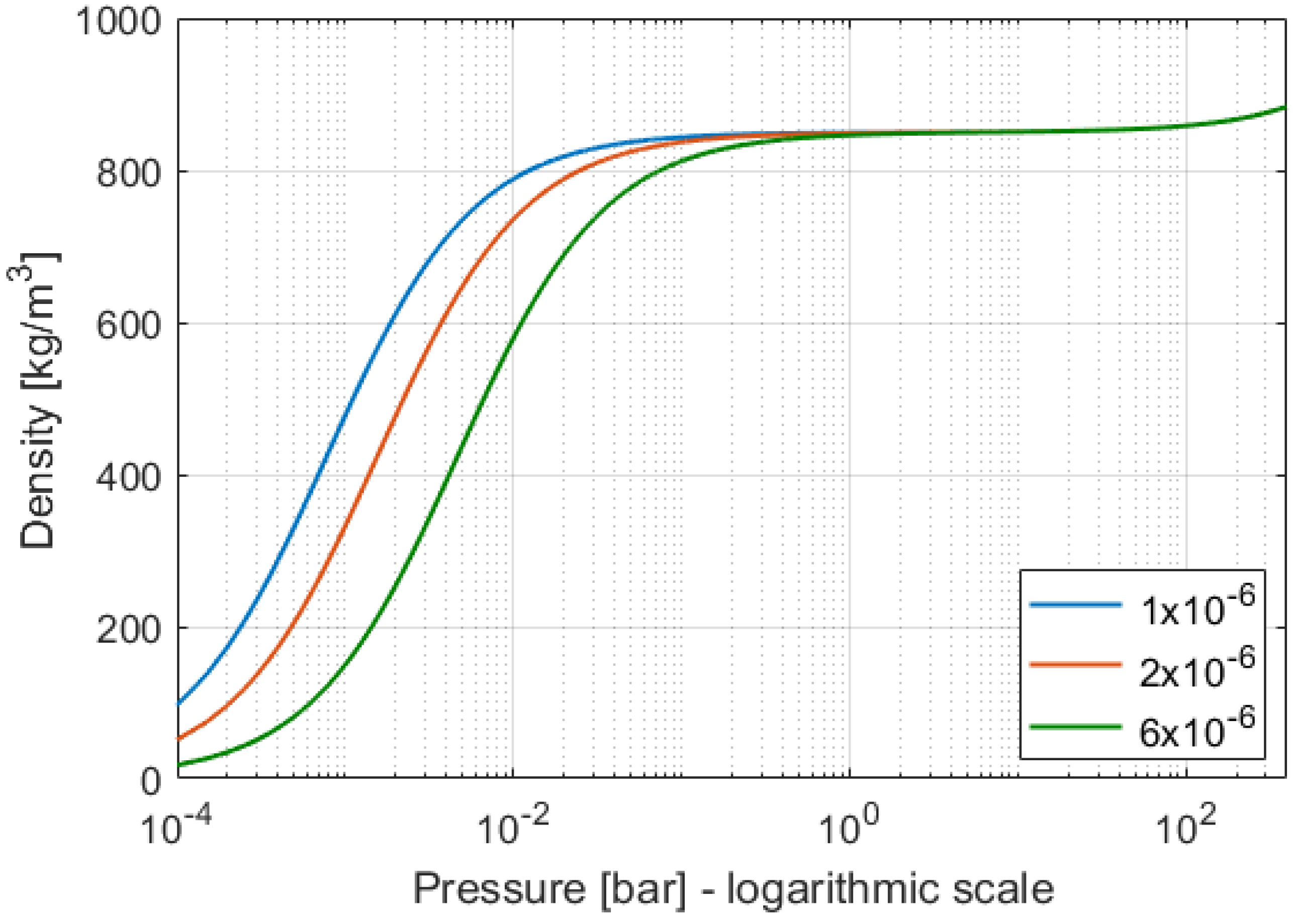
The gaseous phase is modelled through the state equation for ideal gases neglecting any contribution of oil vapor and the effects of high pressure on the gas compressibility factor. The mixture volume is the sum of the volume of each component, expressed for the unit of mass as:
and the state equation of the mixture is:
The fluid density versus pressure for different values of gas to liquid mass fraction is presented in Figure 1; the gas effect is evident in the lower pressure range.
3. Fluid Dynamic Model
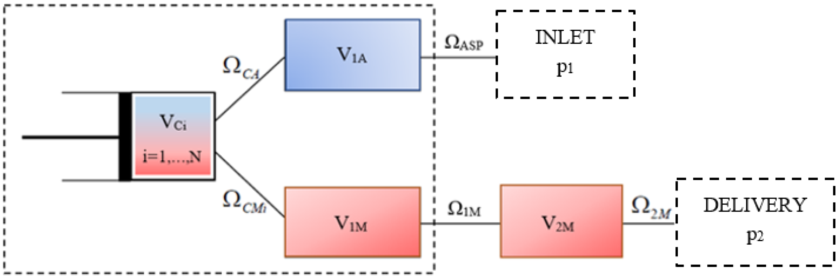
The fluid flow is simulated by means of a mathematical model based on the filling and emptying method (F&E). The axial piston pump has been divided in both fixed and variable volumes in order to apply the F&E model, as shown in Figure 2.
The constant volumes V1A and V1M represent the internal cavities of the pump casing at the suction and delivery side; they are connected with the external ports and with the cylinders (VCi represented as variable volumes) by means of variable orifices.
In order to simulate the circuit on the test bench, an additional volume, V2M, has been added to represent the portion of pipe that connects the delivery of the pump to the valve that simulates the load, Ω2M. This latter is a variable orifice that permits the pressurization of delivery side of the pump; downstream of this orifice there is the tank. The generalized Bernoulli’s equation, neglecting the gravity term, is:
c · dc = −v · dp
Substituting Equation (2) in the second member of Equation (3) and integrating, the fluid velocity in a throat is found:
The upstream pressure pt is the stagnation pressure, while ps is the static downstream pressure.
The pressure inside each chamber is determined through the continuity equation; in particular, for the cylinder volume:
where the first term is related to the mass exchange, the second term to the effects of compressibility, under isothermal conditions, and the last term considers the rate of variation of the volume produced by the movement of the piston, whose position is defined by the z coordinate. Fixed volumes are modeled by means of Equation (5), in which the third term is null.
The fluid dynamic model also considers the effects of fluid inertia in the delivery volume of the pump body. The effects of fluid inertia are important at the beginning of the delivery stroke, when the edge of the cylinder block port begins to uncover the groove and the sudden fluid acceleration induces additional pressure pulsations in the cylinder [19].
The inertia of the fluid is modeled by an appropriate formulation of the momentum equation, which can be expressed as:
The control volume considered is delimited by the port plate and the pump delivery port.
The first and second terms in the first member of Equation (6) are the flux of momentum that enters and exits the volume, respectively; the term in brackets is the sum of the forces acting on the fluid in the time dt; the second member represents the change of momentum.
The considered forces are the surface term acting on a permeable control area () and the normal pressure forces acting on an impermeable surface (), while the body force () is neglectable.
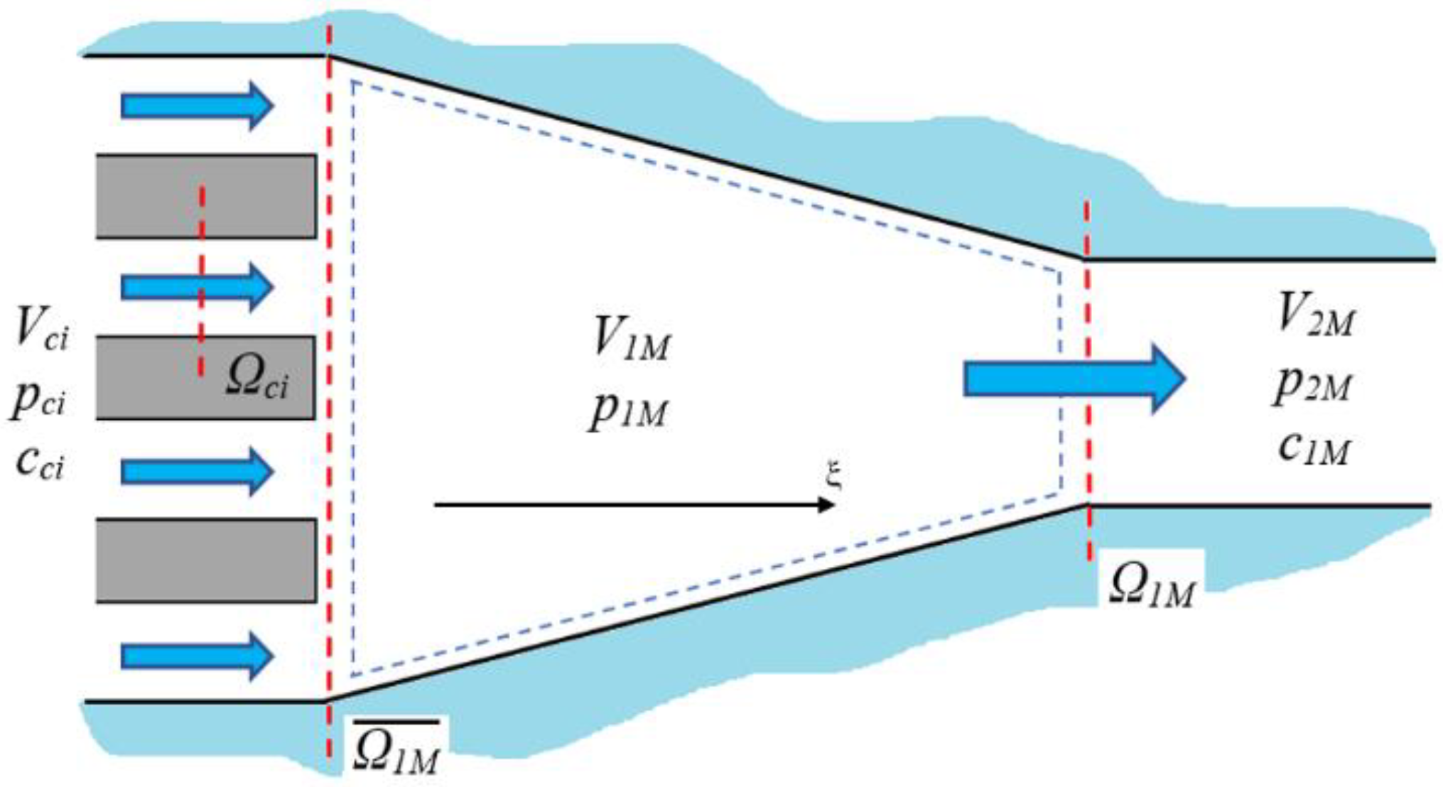
The vector terms of the flux of momentum projected on ξ axis, represented in Figure 3, are:
The forces on permeable surfaces are:
The throat area between cylinders and delivery volume depends on the cylinder block position that has been evaluated through the kinematic model.
Figure 3 shows the section identified with , which is partially an impermeable surface, on which the pressure p1M acts. The forces on impermeable surfaces are expressed by:
where the following terms are defined:
, represents the impermeable surface portion of , where the pressure p1M acts;
, impermeable surface portion due to the difference between and , on which acts a pressure p′ that has been assumed equal to a mean value between the pressure in the control volume V1M and the pressure in the delivery one V2M.
The rate of change of momentum in the control volume is:
The fluid velocity c* considered is c1M.
In conclusion, the system of differential equations that describes the fluid dynamic model is:
4. Dynamic Model
The dynamic model of the pump has been realized focusing on the determination of the equilibrium position reached by the swash plate. Preliminarily, a kinematic analysis has been conducted in order to evaluate the instantaneous piston displacement, defined as a function of the rotation angle of the cylinder block and of the swash plate angular position, through geometrical considerations. In Figure 4, the geometrical sketch of the cylinder block, with a single piston, the slippery and the swash plate, is shown.
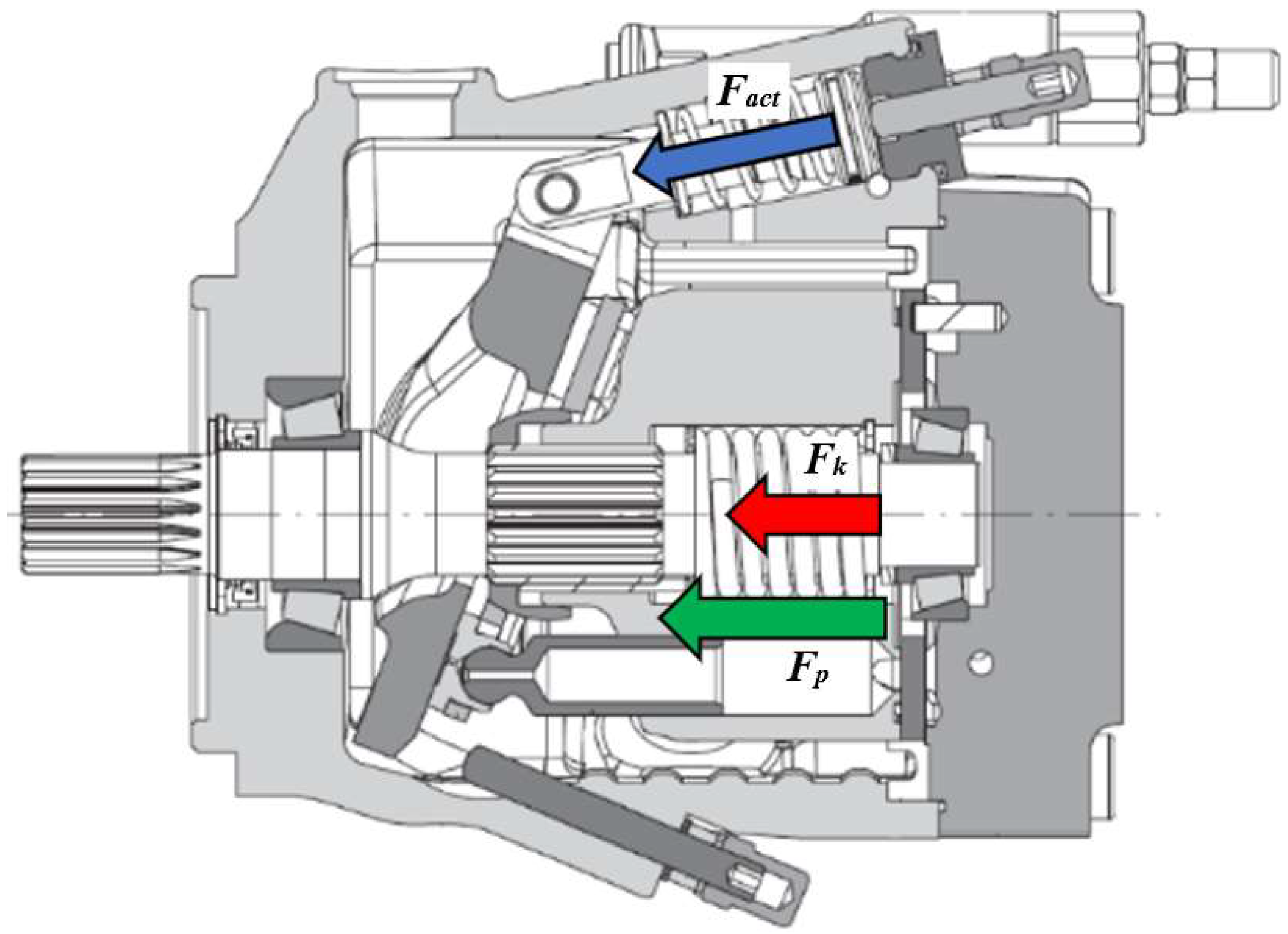
The equilibrium position of the swash plate is determined by the equilibrium of the forces acting on it. In Figure 5 a sectional view of the pump is represented and the forces applied on the swash plate are highlighted. In detail, the forces acting on the swash plate are the forces exerted by the pistons (Fp), by the cylinder block spring (Fk) and by the displacement actuator (Fact).
The rotation equilibrium equation around the axis of the oscillating plate, indicated by the spot in Figure 4, is:
where J represents the overall mass moment of inertia of the swash plate, slipper and slipper hold-down; Ta the friction torque; Tpi the torque exerted by the i-th piston; Tk the torque due to the spring and Tact the torque due to the control actuator.
From Equation (12) it is possible to calculate the swash plate acceleration and, with a double integration, its angular position. The torque due to the i-th chamber can be evaluated from the force exerted by the corresponding piston:
The force FRi is the resultant force of the i-th piston normal to the swash plate. The force value and the moment-arm bi are defined as follows:
The pressure trend inside each cylinder is known from the fluid dynamic model, so the corresponding force acting on the swash plate is easily determinable.
For the calculation of the term due to the viscous friction, the viscous friction coefficient f is expressed as follows [22]:
The spring inside the cylinder block generates a torque on the oscillating plate due to the eccentricity e, Figure 4:
where Fk is the spring preload.
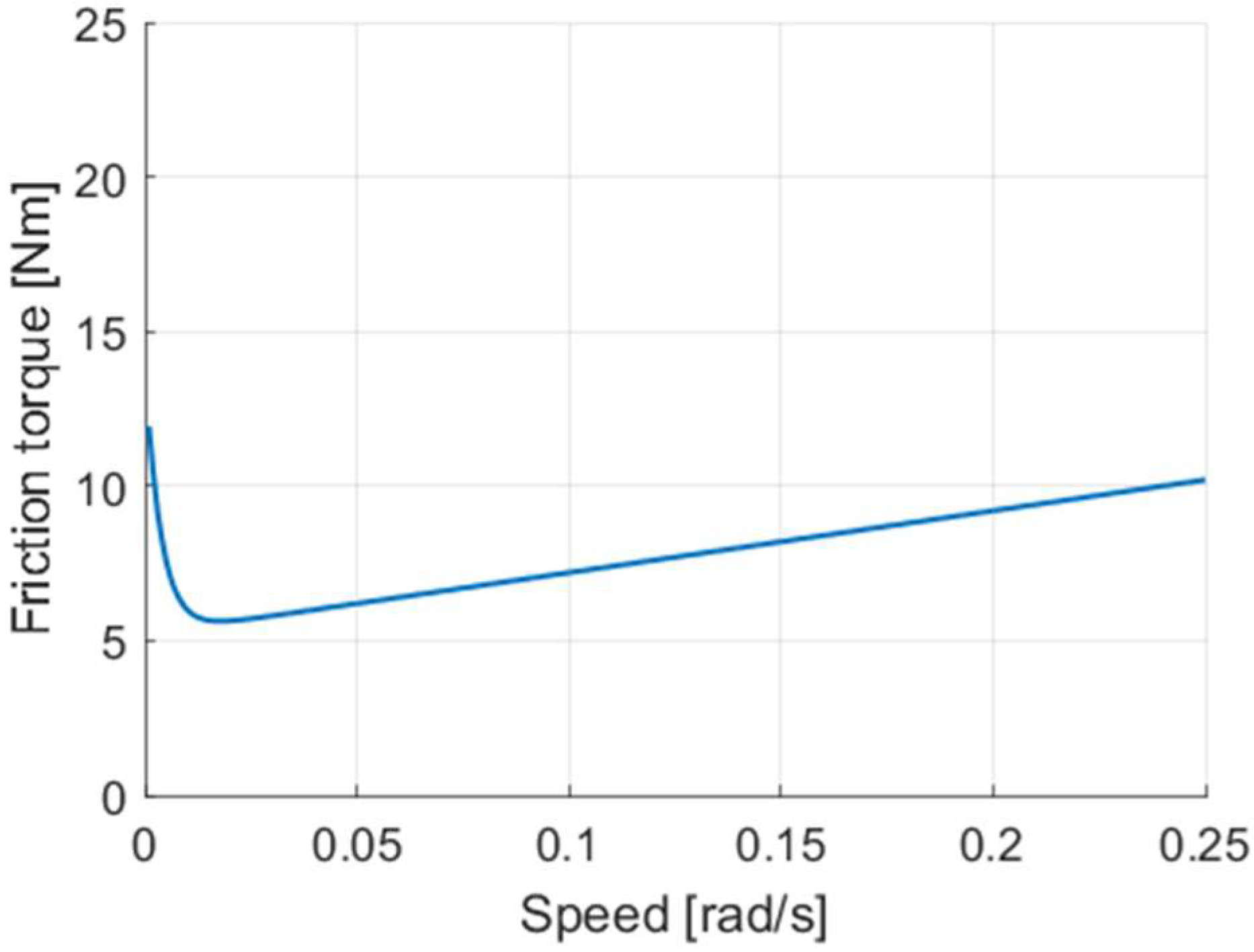
The friction torque due to the coupling between the swash plate and the bearings is studied with the Karnopp friction model. This allows defining the static and viscous friction as a function of the swash plate angular velocity. An angular velocity threshold value is identified: if the swash plate velocity is smaller than that value, the swash plate velocity is set to zero and the friction torque is the minimum value between the torque acting on the swashplate (Ttot) and the maximum static friction torque (Tsmax); conversely, if the swash plate velocity is greater, the friction torque acting on the swash plate is defined by Stribeck’s and viscous effects. The Karnopp model mathematical formulation is the following:
The Karnopp friction coefficients have been calibrated with experimental data: different step tests under many working conditions have been provided in order to achieve the best possible fitting between the simulation results and experimental measurements. Figure 6 shows the friction torque as a function of the swash plate angular speed, according to Karnopp model, adopting the optimized coefficients.
The displacement actuator is controlled by a servo valve that has been mounted in substitution of the original mechanical control in order to modify the pump displacement at higher frequency. The force exerted by the actuator on the swash plate is evaluated from the pressure inside the chamber applied on the actuator surface; the pressure is calculated by means of the F&E method, knowing the mass flow rate provided by the servo valve. The servo valve has the purpose of managing the flow towards the displacement control actuator to maintain a fixed differential pressure through the control orifice by modulating the pump displacement, allowing the pump to work in a load sensing logic.
The servo valve is actuated by an ideal solenoid. The mechanical aspect of the component is studied as a second order system and the instantaneous position of the spool is calculated using Newton’s second law.
The solenoid is actuated through a signal provided by a dedicated controller, whose aim is to compare the sum of the load sensing pressure (pLS) and the pump margin with the pump delivery pressure (pd), in order to properly modulate the displacement of the pump to minimize the error between the two values.
5. Experimental Activity
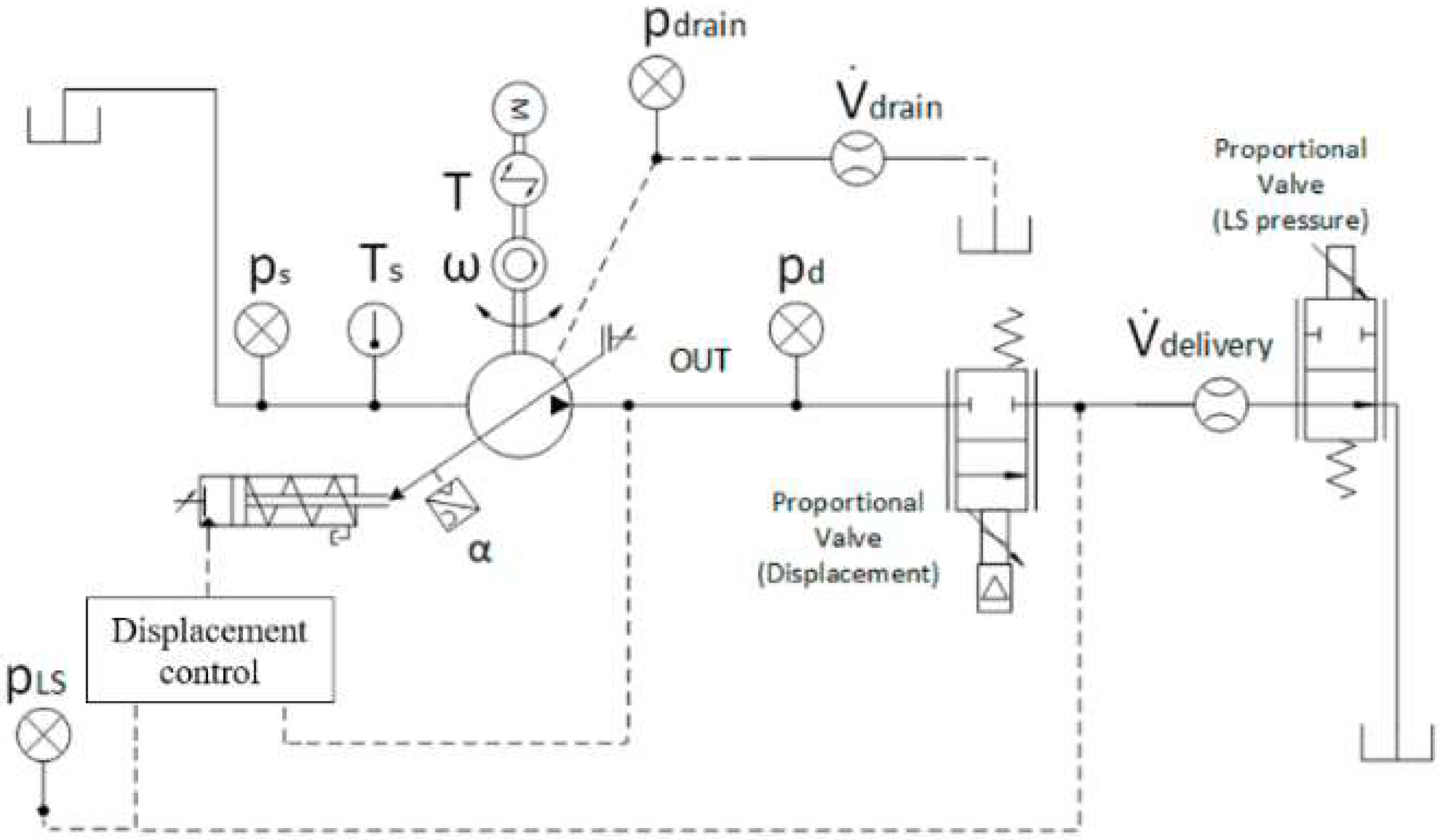
Several experimental activities have been conducted in order to validate the mathematical model. The tests have been performed on the test bench in the Laboratory of the Engineering and Architectural Department at the University of Parma. The pump object of study is the variable displacement axial piston pump Casappa® MVP60-84, which is installed in a Load Sensing (LS) circuit. The main characteristics of the pump are listed in Table 1. The pump is also equipped with many sensors with the aim of acquiring the following data: suction fluid temperature; delivery pressure; swash plate angular position; torque absorbed by the shaft; shaft speed; delivery flow rate and drain flow rate. The hydraulic scheme of the experimental layout is reported in Figure 7 and the transducers features are shown in Table 2.
6. Model Validation
The fluid dynamic model, system Equation (11), and the dynamic model, Equation (12), are solved simultaneously. The models have been realized in Simulink® environment (version 9.1, MathWorks Inc., Natick, MA, USA) by adopting a variable-step solver ode23tb, with a maximum step size of and with relative and absolute tolerances of .
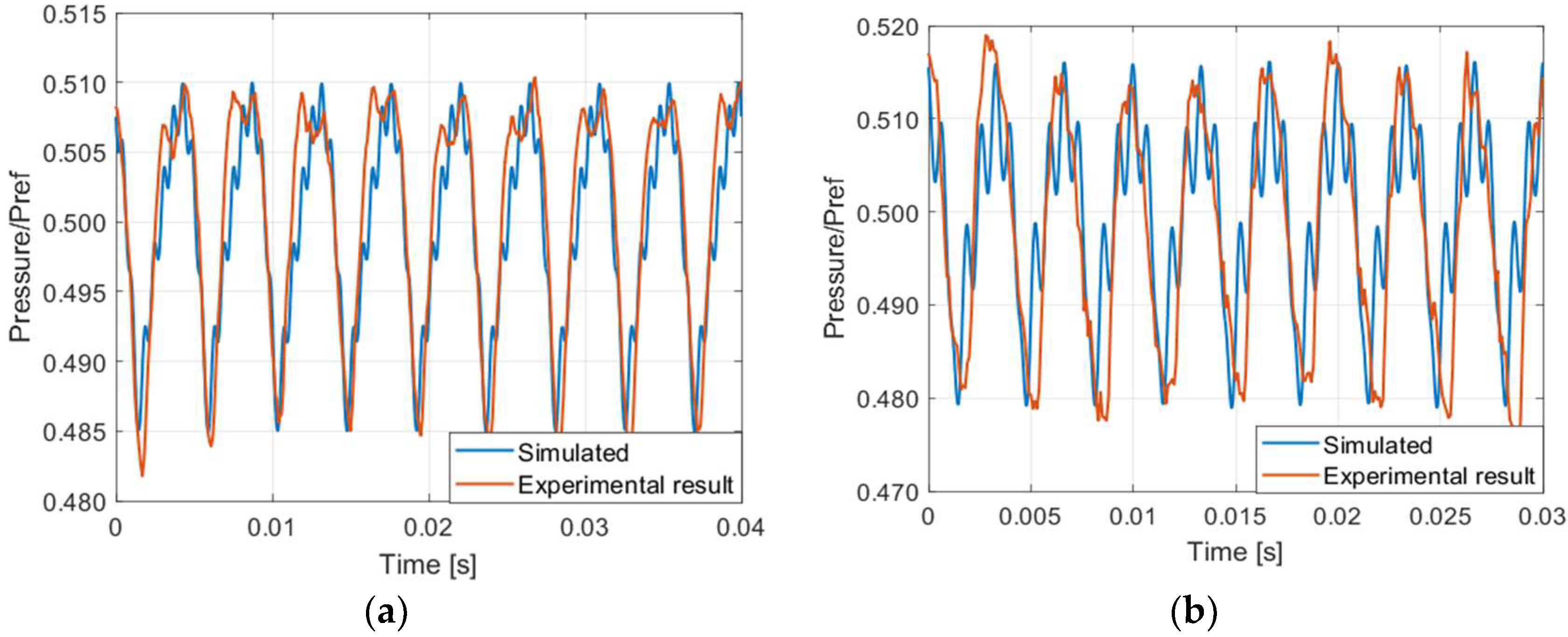
Both the fluid dynamic model and the dynamic model have been validated by comparison with experimental data. For the fluid dynamic model, several tests have been conducted under many different working conditions; the results are presented in Figure 8a,b, where a single shaft revolution is shown. The delivery mean pressure of Figure 8b is higher than the mean pressure of case reported in Figure 8a. The pressure has been divided by a reference value for confidential reasons. Based on the analysis of these cases, a satisfactory agreement between predicted results and experiments data, in relation to the target of the model, is found.
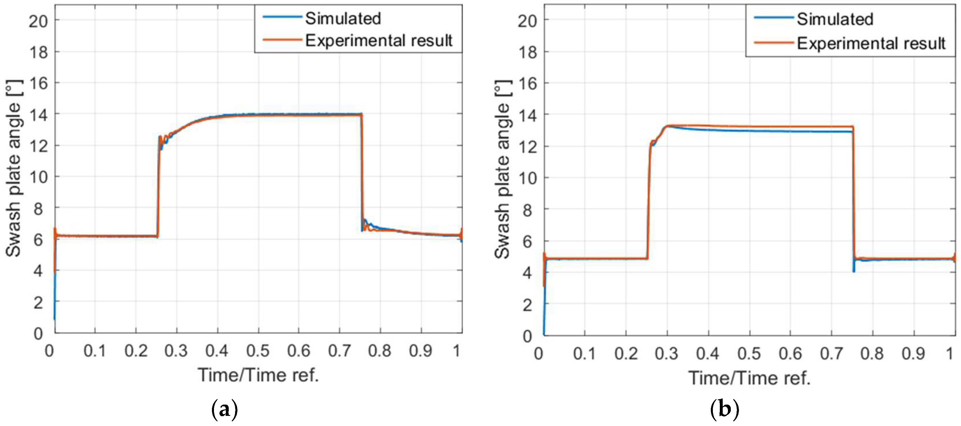
Regarding the dynamic model, several step tests have been performed under many different working conditions and some of the results are reported in Figure 9a,b, where the time scale has been normalized for confidential reasons. Both the step-up and the step-down phases are simulated in an appropriate manner for each test. In general, the model is able to predict properly the swash plate position.
7. Active Control of the Pressure Ripple through the Swash Plate Control
The possibility of reducing the pressure ripple by continuously changing the inclination of the swash plate is presented. The basic principle consists of changing the tilt angle of the swash plate around the equilibrium position to properly modify the machine displacement. In this way the law of motion of the pistons and the instantaneous delivery flow rate are altered: as a consequence, the delivery pressure profile is modified. In order to obtain a variation on the swash plate angular position, the active control system actuates the servo valve. The control strategy consists of decreasing the pump displacement when the instantaneous pressure is higher than the mean value, vice versa when the pressure is lower.
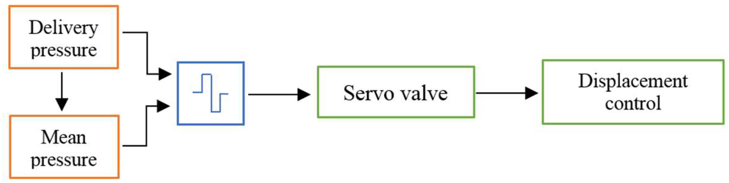
The servo valve is actuated by means of a square wave signal with a proper phase shift with the delivery pressure, in order to take into account the response time of the whole mechanic and hydraulic systems. A square wave signal has been chosen because of its simplicity of implementation since this is a preliminary work aimed to verify the potential of the proposed solution. In Figure 10 the diagram representing the control strategy adopted to obtain the swinging of the oscillating plate is presented: in detail, the blue block represents the algorithm which generates the square wave signal for the actuation of the servo valve, starting from the pressure at the delivery side and the mean pressure value required.
The fundamental driving frequency of the servo valve, and therefore of the signal, is expressed by the following equation:
where n is the shaft speed and 9 is the number of pistons for the case considered.
In order to evaluate the potentiality of the proposed solution, the first simulations have been carried out assuming an ideal model representing a system where the masses of the pump and of the servo valve components are not present and the cut-off frequency of the servo valve is supposed infinite.
The servo valve driving signal is generated by a proportional controller, which has the purpose of minimizing the error defined as the difference between the instantaneous delivery pressure and the mean desired pressure: this signal is added to the one which allows the pump to work in load sensing logic, introduced in Section 4. The simulation results are presented in the following figures where the mass flow rate, the delivery pressure and the Fast Fourier Transform (FFT) amplitude have been divided by a reference value for confidential reasons. The displacement control system allows the swash plate to vary its tilt angle, around the equilibrium position, of 5 degrees in amplitude, as shown in Figure 11: in this way, the instantaneous flow rate has been changed, as shown in Figure 12a. It is evident that, with respect to the case without the active control, the flow rate fluctuations have been reduced significantly. This has a very positive effect on the delivery pressure oscillations, as shown in Figure 12b, where the pressure ripple profile presents a marked improvement. In particular, it is possible to notice a reduction in the pressure oscillation amplitude of the 67.5% compared to the case without active control, as well as the damping of the oscillations at a higher frequency as confirmed by the FFT reported in Figure 13.
The results based on an ideal model have successfully established the possibility of performing an active control of the pressure ripple, by the movement of the swash plate, and its effectiveness.
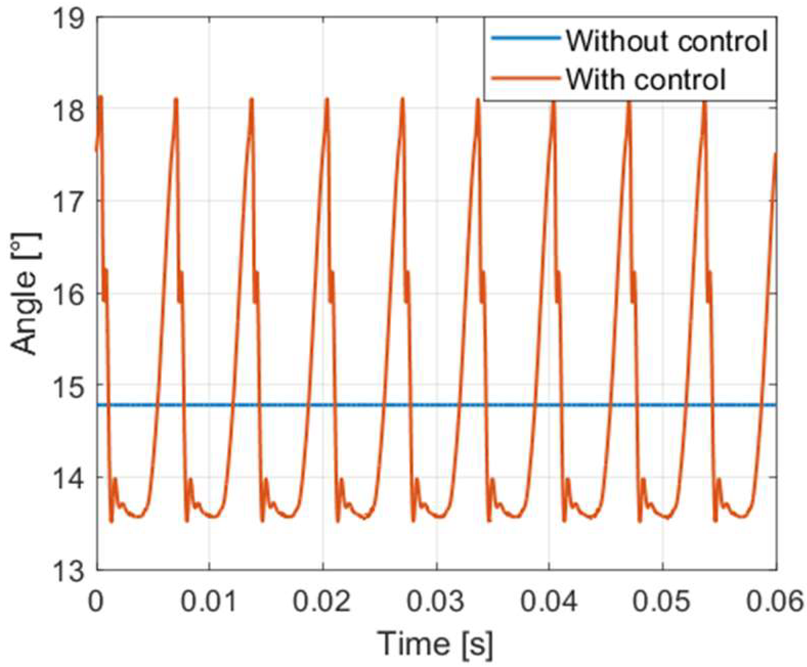
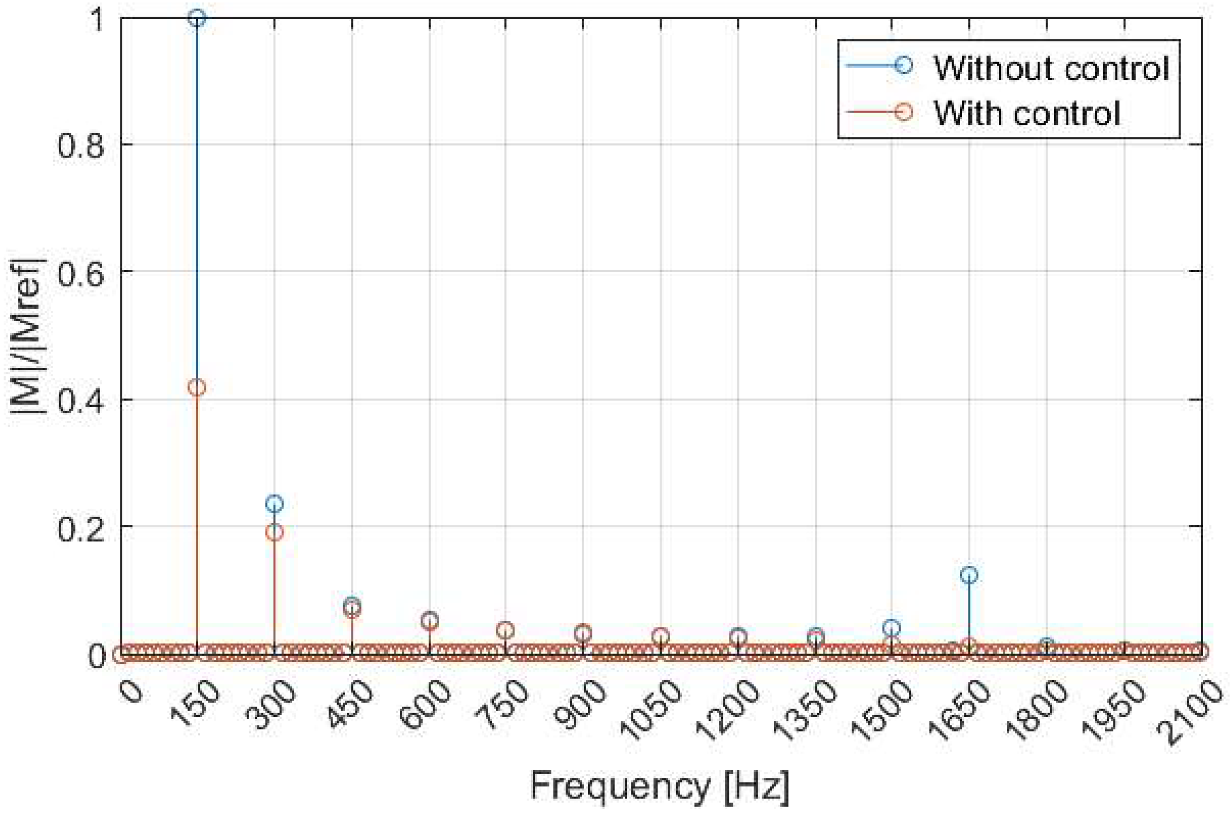
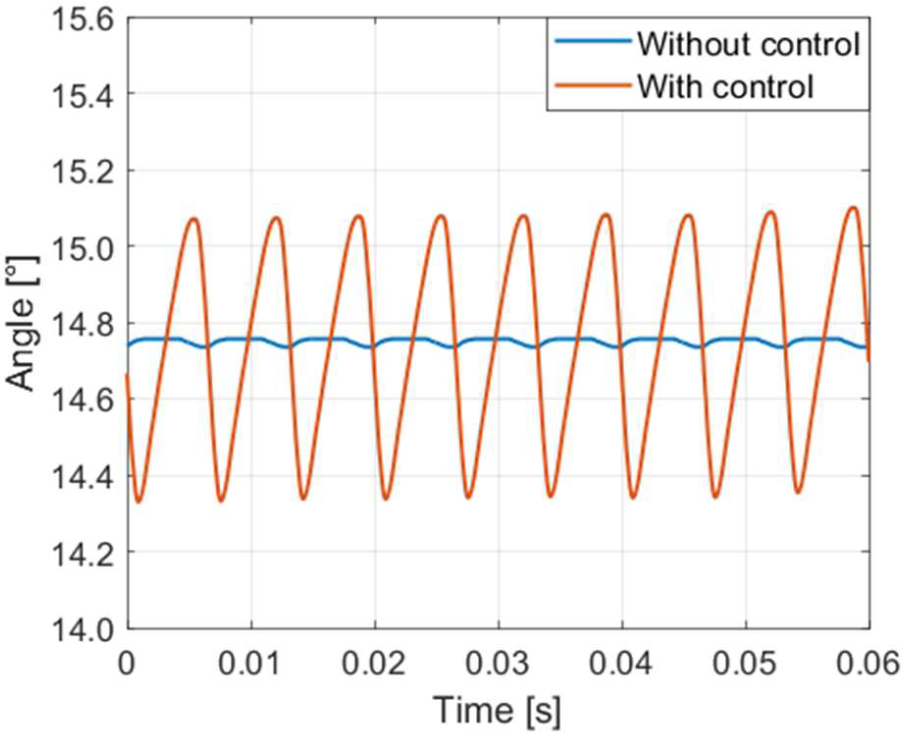
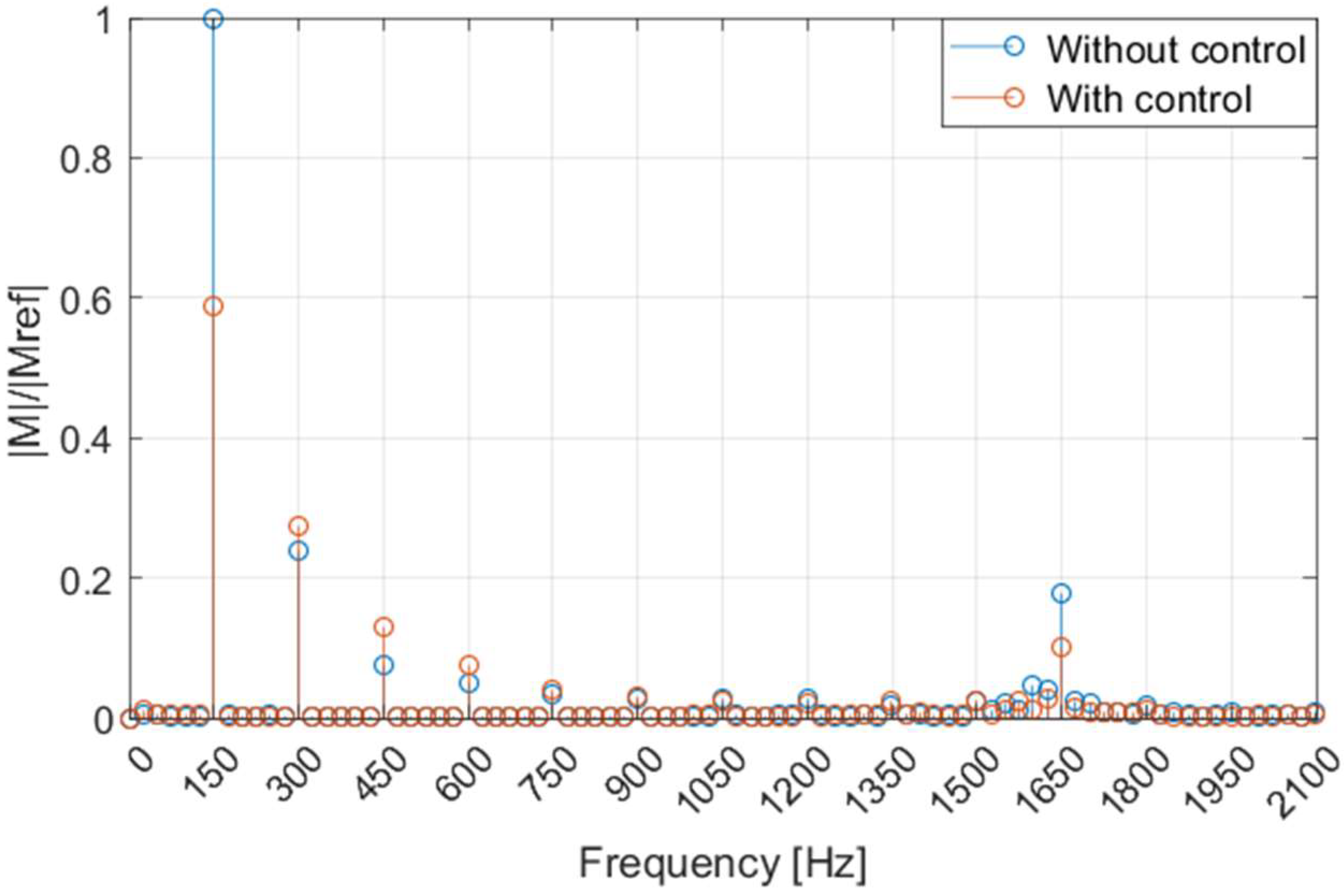
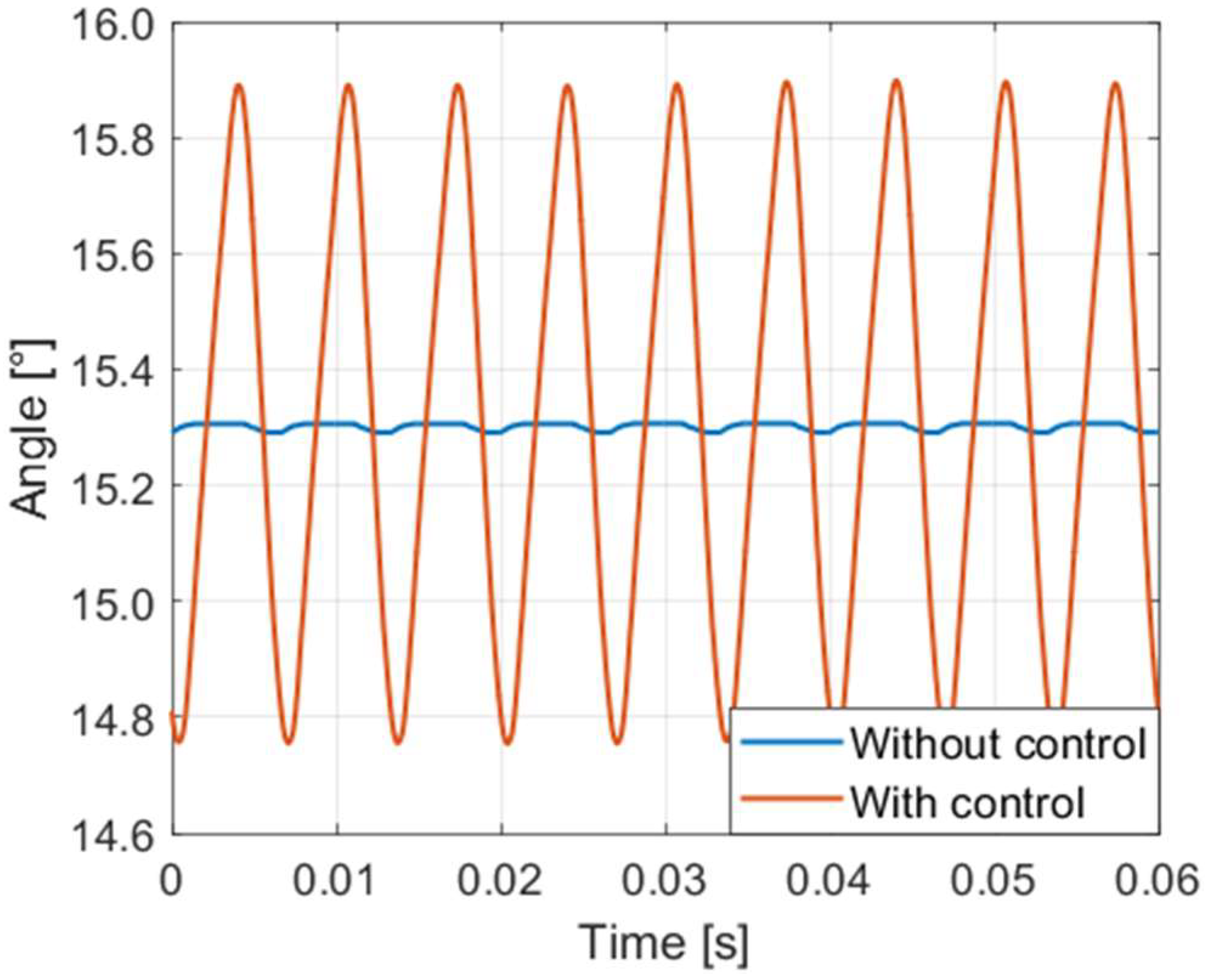
Subsequently, the possibility of implementing this type of active control in a model of the pump including the dynamic effects has been studied. It is straightforward that the type of control presented in the ideal case is not physically possible. In fact, to achieve similar results, the displacement control system and the actuator itself should intervene at very high frequencies, continuously following the signal provided by the controller. Considering the model of the real system, where the mass of the components is considered in both the pump and the servo valve model, the results about the swash plate angular position are reported in Figure 14, without and with the control system. The displacement control system is able to change the amplitude of the angular position of the swash plate around its equilibrium position of only 0.7 degrees; therefore, in the simulated real case the obtainable maximum amplitude of the swash plate oscillations is much lower with respect to the ideal case (5 degrees). The delivery flow rate is shown in Figure 15a, where only a slight reduction in the amplitude can be appreciated, but without any significant damping. The same consideration can be made for the pressure profile presented in Figure 15b, showing a limited decrease in the amplitude of the pressure oscillations around the mean value, also confirmed by the analysis of the Fourier transform visible in Figure 16, but leaving almost unaltered the high frequency components.
Therefore, with the real pump model, the improvements that can be obtained are quite limited. The main cause is the narrow variation of the angular position of the plate around the equilibrium position (0.7 degrees), which does not allow obtaining a variation of the motion law of the pistons sufficient to significantly modify the delivered flow rate and therefore the pressure ripple. In fact, in order to reduce the displacement, it is necessary to pressurize the actuator chamber with the oil coming from the high pressure line. On the contrary, to increase the displacement, it is essential to drain part of the oil to the tank. In the latter case, the forces acting on the actuator, which define its equilibrium position, are given by the action of the pumping elements, due to the eccentricity of the cylinder block assembly, and by the spring inside the actuator. In the considered pump there is a disparity between the magnitudes of the forces on the actuator in the two cases. During the decrease phase the forces exerted by the fluid is much greater and this allows changing the position of the oscillating plate very quickly. Conversely, during the phase of increase of the displacement, being the force due to the spring lower, a longer time interval is necessary. This has negative consequences on the possibility of having greater ranges of the angular position of the swash plate, even at low speed where the driving frequency is lower.
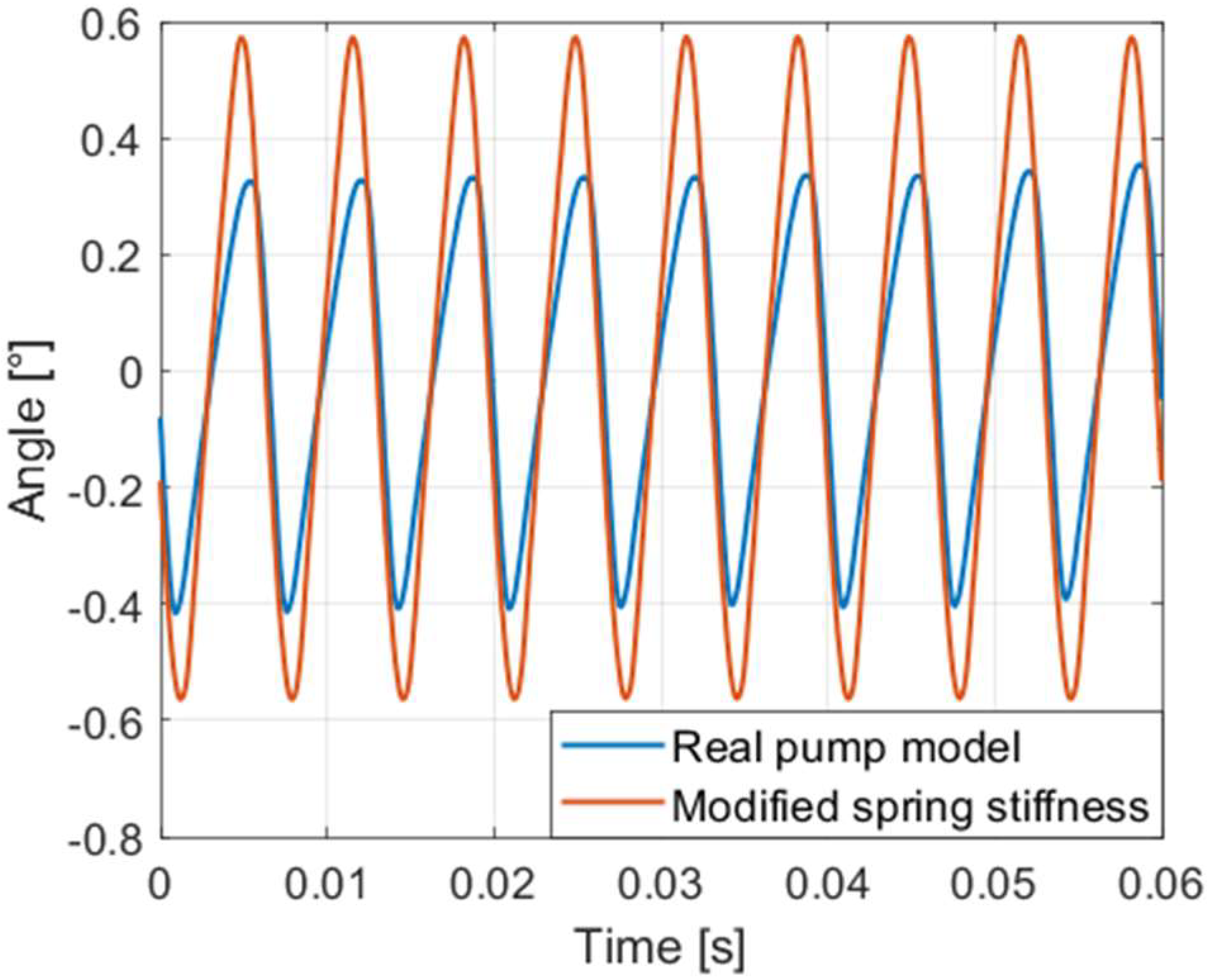
To overcome this problem, different actuation solutions could be investigated, but in this paper, for brevity, the desired effect has been simply modelled by increasing the spring stiffness, omitting any pump functional drawbacks. In this way it is possible to obtain better dynamics in the phase of the displacement increment, as can be seen in Figure 17, where a comparison between the angular position calculated with both the real pump model and the modified spring stiffness is shown. As proof of the best dynamic performance achieved, the curve relating to the modified case has a greater slope during the phase of increment of the displacement. In this way, it is also possible to obtain a greater excursion in the angular position of the swash plate in the same time interval in the modified case with respect to the real case; as a matter of fact the oscillation amplitude reaches the value of 1.1 degrees, Figure 18, improving the previous result of 0.7 degrees. In the graph the mean value has been subtracted from each curve in order to overlap them.
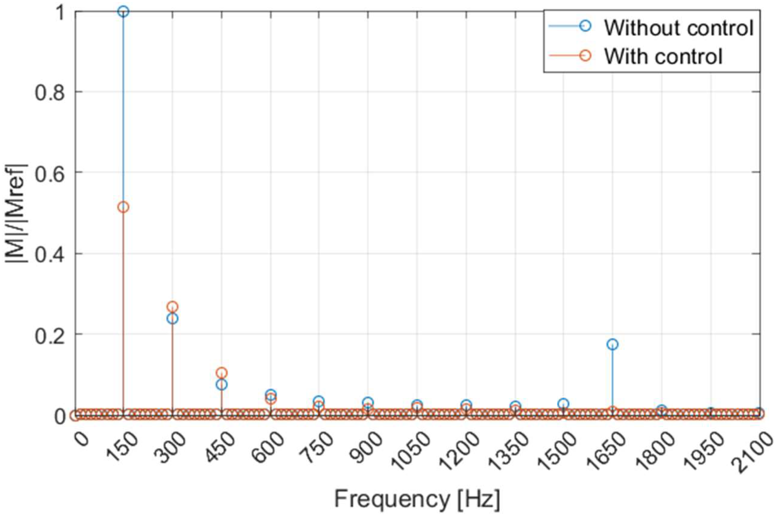
The delivery flow rate shows a marked improvement due to the swash plate oscillation with a considerable reduction in amplitude, as shown in Figure 19a, and consequently, also the delivery pressure profile presents a significant decrease, equal to 57% compared to the case in the absence of control, represented in Figure 19b. Furthermore, the higher stiffness of the swash plate actuation system limits the amplitudes of the high frequency components of the pressure ripple. The harmonic components present at high frequency are completely attenuated and those at medium frequency are damped, as demonstrated by the FFT in Figure 20.
8. Conclusions
In this paper the possibility of reducing the delivery pressure ripple in piston pumps through a controlled oscillating motion of the swash plate has been theoretically investigated. The mathematical model of an axial piston pump has been presented and applied to carry out the analysis. The model has been experimentally validated in terms of delivery pressure ripple and step response. Finally, a servo valve has been modelled for implementing the high dynamic control of the pump displacement.
Firstly, the validity of the working principle has been demonstrated for an ideal model, where the components have been assumed without mass. The theoretical analysis has shown interesting results with a significant reduction of flow rate oscillations and, consequently, a markable decrease of the pressure ripple.
If the real masses are considered, an attenuation of the pressure oscillation is still possible, even if quite limited. The reason is the low dynamic response of the displacement control of the reference pump due to the high inertia of the components. Nevertheless, it has been demonstrated that with a quite simple modification of the displacement control, in order to reach a very short time response during both the increase and the decrease phase of the pump displacement, good results can be achieved. Hence, it is reasonable that better results could be obtained if some components of the displacement control were properly redesigned for this specific application.
Overall, although the use of a servo valve implies an increment of cost, the principle of the active control of the pressure ripple through the oscillations at high frequency of the swash plate seems promising and deserves further in-depth analyses.
Author Contributions
P.C. conceived the study and wrote the draft paper, supervising the entire activity; M.P. and F.S. performed the experimental tests, applying the methodology, in order to obtain the results; M.R. analyzed the results and examined the final document.
Funding
This research received no external funding.
Acknowledgments
The authors would like to acknowledge the active support of this research by Casappa S.p.A., Parma, Italy.
Conflicts of Interest
The authors declare no conflict of interest.
Nomenclature
| Acil | Piston crown surface [m2] |
| a | Piston offset [m] |
| α | Swash plate angle [rad] |
| B | Bulk modulus [Pa] |
| c | Velocity [m/s] |
| dp | Piston diameter [m] |
| ξ | Abscissa |
| FB | Body forces [N] |
| hp | Radial clearance between piston and guide [m] |
| Lp | Length of contact between piston and chamber [m] |
| μ | Fluid dynamic viscosity [Pa·s] |
| Mass flow rate [kg/s] | |
| Mp | Piston mass [kg] |
| n | Shaft speed [r/min] |
| N | Number of cylinders |
| Ω | Cross sectional area [m2] |
| p | Pressure [Pa] |
| Momentum flux [kg·m/s2] | |
| ρ | Density [kg/m3] |
| R | Piston-pitch radius [m] |
| RG | Specific gas constant [J/(kg·K)] |
| t | Time [s] |
| TG | Temperature [K] |
| θ | Block cylinders angular position [rad] |
| v | Volume for the unit of mass [m3/kg] |
| V | Volume [m3] |
| Vc | Cylinder volume [m3] |
| Volume flow rate [m3/s] | |
| y | Gas to liquid mass fraction |
| Piston velocity [m/s] | |
| Abbreviation | |
| F&E | Filling and emptying |
| FFT | Fast Fourier Transform |
| Subscript | |
| 0 | Reference value |
References
- Ivantysyn, J.; Ivantysynova, M. Hydrostatic Pumps and Motors: Principles, Designs, Performance, Modelling, Analysis, Control and Testing; Tech Books International: New Delhi, India, 2003; ISBN 81-88305-08-1. [Google Scholar]
- Ye, S.; Zhang, J.; Xu, B. Noise Reduction of an Axial Piston Pump by Valve Plate Optimization. Chin. J. Mech. Eng. 2018, 31, 57. [Google Scholar] [CrossRef]
- Pan, M.; Ding, B.; Yuan, C.; Zou, J.; Yang, H. Novel Integrated Control of Fluid-Borne Noise in Hydraulic Systems. In Proceedings of the BATH/ASME 2018 Symposium on Fluid Power and Motion Control FPMC2018, Bath, UK, 12–14 September 2018. [Google Scholar]
- Kim, T.; Ivantysynova, M. Active Vibration/Noise Control of Axial Piston Machine Using Swash Plate Control. In Proceedings of the ASME/BATH 2017 Symposium on Fluid Power and Motion Control, Sarasota, FL, USA, 16–19 October 2017. [Google Scholar] [CrossRef]
- Wieczorek, U.; Ivantysynova, M. Computer aided optimization of bearing and sealing gaps in hydrostatic machines—The simulation tool CASPAR. Int. J. Fluid Power 2002, 3, 7–20. [Google Scholar] [CrossRef]
- Ivantysynova, M.; Grabbel, J.; Ossyra, J. Prediction of swash plate moment using the simulation tool CASPAR. In Proceedings of the ASME International Mechanical Engineering Congress, New Orleans, LO, USA, 17–22 November 2002. [Google Scholar] [CrossRef]
- Ivantysynova, M.; Huang, C. Investigation of the gap flow in displacement machines considering the elastohydrodynamic effect. In Proceedings of the 5th JFPS International Symposium on Fluid Power, Nara, Japan, 12–15 November 2002; pp. 219–229. [Google Scholar]
- Edge, K.A.; Darling, J. The pumping dynamics of swash plate piston pumps. J. Dyn. Syst. Meas. Control Trans. ASME 1989, 111, 307–312. [Google Scholar] [CrossRef]
- Borghi, M.; Zardin, B. Axial Balance of External Gear Pumps and Motors: Modelling and Discussing the Influence of Elastohydrodynamic Lubrication in the Axial Gap. In Advances in Multidisciplinary Engineering; ASME Press: New York City, NY, USA, 2016; Volume 15. [Google Scholar]
- Harrison, A.M.; Edge, K.A. Reduction of axial piston pump pressure ripple. Proc. IMechE 2000, 214, 53–63. [Google Scholar] [CrossRef]
- Edge, K.A.; Johnston, D.N. A new method for evaluating the fluid borne noise characteristics of positive displacement pumps. In Proceedings of the Seventh International Fluid Power Symposium, Bath, UK, 16–18 September 1986; pp. 253–260. [Google Scholar]
- Edge, K.A.; Liu, Y. Reduction of piston pump pressure ripple. In Proceedings of the 2nd International Conference on Fluid Power Transmission and Control, Hangzhou, China, 20–22 March 1989; pp. 779–784. [Google Scholar]
- Frosina, E.; Senatore, A.; Buono, D.; Stelson, K.A.; Wang, F.; Mohanty, B.; Gust, M.J. Vane pump power split transmission: Three dimensional computational fluid dynamic modeling. In Proceedings of the ASME/BATH 2015 Symposium on Fluid Power and Motion Control, FPMC2015, Chicago, IL, USA, 12–14 October 2015. [Google Scholar] [CrossRef]
- Corvaglia, A.; Rundo, M. Comparison of 0D and 3D Hydraulic Models for Axial Piston Pumps. Energy Procedia 2018, 148, 114–121. [Google Scholar] [CrossRef]
- Mancò, S.; Nervegna, N.; Lettini, A.; Gilardino, L. Advances in the simulation of axial piston pumps. In Proceedings of the 5th JFPS International Symposium on Fluid Power, Nara, Japan, 12–15 November 2002; pp. 251–258. [Google Scholar] [CrossRef]
- Johansson, A.; Andersson, J.; Palmberg, J.O. Optimal Design of the Cross-Angle for Pulsation Reduction in Variable Displacement Pumps. In Proceedings of the Bath Workshop on Power Transmission and Motion Control, Bath, UK, 11–13 September 2002. [Google Scholar]
- Pettersson, M.; Weddfelt, K.; Palmberg, J.O. Prediction of Structural and Audible Noise from Axial Piston Pumps Using Transfer Functions. In Proceedings of the 8th Bath International Fluid Power Workshop, Bath, UK, 20–22 September 1995. [Google Scholar]
- Casoli, P.; Vacca, A.; Franzoni, G.; Berta, G.L. Modelling of fluid properties in hydraulic positive displacement machines. Simul. Model. Pract. Theory 2006, 14, 1059–1072. [Google Scholar] [CrossRef]
- Casoli, P.; Vacca, A.; Franzoni, G. Simulation and analysis of fluid inertia effects in the delivery an inlet volume of axial piston pumps. In Proceedings of the Ninth Scandinavian International Conference on Fluid Power, SICFP’05, Linköping, Sweden, 1–3 June 2005. [Google Scholar]
- Zeiger, G.G.; Akers, A.A. Torque on the Swashplate of an Axial Piston Pump. ASME. J. Dyn. Syst. Meas. Control 1985, 107, 220–226. [Google Scholar] [CrossRef]
- Lin, S.; Akers, A.; Zeiger, G. Oil Entrapment in an Axial Piston Pump and its Effect Upon Pressures and Swashplate Torques. In Proceedings of the 42nd National Conference on Fluid Power, Chicago, IL, USA, March 1987; pp. 113–124. [Google Scholar]
- Schoenau, G.J.; Burton, R.T.; Kavanagh, G.P. Dynamic Analysis of a Variable Displacement Pump. ASME. J. Dyn. Syst. Meas. Control 1990, 112, 122–132. [Google Scholar] [CrossRef]
- Casoli, P.; Anthony, A. Gray box modeling of an excavator’s variable displacement hydraulic pump for fast simulation of excavation cycle. Control Eng. Pract. 2013, 21, 483–494. [Google Scholar] [CrossRef]
- Casoli, P.; Gambarotta, A.; Pompini, N.; Riccò, L. Coupling excavator hydraulic system and internal combustion engine models for the real-time simulation. Control Eng. Pract. 2015, 26–37. [Google Scholar] [CrossRef]
- Casoli, P.; Gambarotta, A.; Pompini, N.; Riccò, L. Development and application of co-simulation and control-oriented modeling in the improvement of performance and energy saving of mobile machinery. Energy Procedia 2014, 45, 849–858. [Google Scholar] [CrossRef]
- Casoli, P.; Riccò, L.; Campanini, F.; Bedotti, A. Hydraulic Hybrid Excavator—Mathematical Model Validation and Energy Analysis. Energies 2016, 9, 1002. [Google Scholar] [CrossRef]
- Casoli, P.; Anthony, A.; Riccò, L. Modeling simulation and experimental verification of an excavator hydraulic system—Load sensing flow sharing valve model. In Proceedings of the SAE 2012 Commercial Vehicle Engineering Congress, Rosemount, IL, USA, 2–3 October 2012. [Google Scholar] [CrossRef]
- Casoli, P.; Pompini, N.; Riccò, L. Simulation of an Excavator Hydraulic System Using Nonlinear Mathematical Models. Strojniški Vestnik J. Mech. Eng. 2015, 61, 583–593. [Google Scholar] [CrossRef] [Green Version]
- Zhou, J.; Vacca, A.; Casoli, P. A novel approach for predicting the operation of external gear pumps under cavitating conditions. Simul. Model. Pract. Theory 2014, 45, 35–49. [Google Scholar] [CrossRef]
- Rundo, M.; Squarcini, R.; Furno, F. Modelling of a Variable Displacement Lubricating Pump with Air Dissolution Dynamics. SAE Int. J. Engines 2018, 11, 111–126. [Google Scholar] [CrossRef]
Figure 1.
Fluid density versus pressure. Fluid temperature 320 K.

Figure 2.
Volumes considered.

Figure 3.
Scheme of the control volume adopted to study the inertial effect.

Figure 4.
Geometrical scheme for the kinematic model.

Figure 5.
Sectional view of the pump with indicated the forces acting on the swash plate.

Figure 6.
Friction torque.

Figure 7.
Scheme of the experimental layout.

Figure 8.
(a) Delivery pressure at 1500 r/min, swash plate position 12.7°; (b) Delivery pressure at 2000 r/min, swash plate position 12.8°. The mean pressure of case (b) is higher than the one of case (a).
Figure 8.
(a) Delivery pressure at 1500 r/min, swash plate position 12.7°; (b) Delivery pressure at 2000 r/min, swash plate position 12.8°. The mean pressure of case (b) is higher than the one of case (a).

Figure 9.
(a) Step Test: 1500 r/min, pd = 150 bar, spool opening 23–48%; (b) Step Test: 2000 r/min, pd = 50 bar, spool opening 28–47%.
Figure 9.
(a) Step Test: 1500 r/min, pd = 150 bar, spool opening 23–48%; (b) Step Test: 2000 r/min, pd = 50 bar, spool opening 28–47%.

Figure 10.
Scheme of the control strategy adopted for moving the pump swash plate.

Figure 11.
Ideal model. Swash plate position. Shaft speed 1000 r/min.

Figure 12.
(a) Ideal model. Delivery mass flow rate. Shaft speed 1000 r/min; (b) Ideal model. Delivery pressure. Shaft speed 1000 r/min.
Figure 12.
(a) Ideal model. Delivery mass flow rate. Shaft speed 1000 r/min; (b) Ideal model. Delivery pressure. Shaft speed 1000 r/min.

Figure 13.
Ideal model. Delivery pressure FFT. Shaft speed 1000 r/min.

Figure 14.
Swash plate position. Shaft speed 1000 r/min.

Figure 15.
(a) Delivery mass flow rate. Shaft speed 1000 r/min; (b) Delivery pressure. Shaft speed 1000 r/min.
Figure 15.
(a) Delivery mass flow rate. Shaft speed 1000 r/min; (b) Delivery pressure. Shaft speed 1000 r/min.

Figure 16.
Delivery pressure FFT. Shaft speed 1000 r/min.

Figure 17.
Comparison of the angular position of the swash plate between the real pump model and the modified one.
Figure 17.
Comparison of the angular position of the swash plate between the real pump model and the modified one.

Figure 18.
Real pump model with higher spring stiffness. Swash plate position. Shaft speed 1000 r/min.
Figure 18.
Real pump model with higher spring stiffness. Swash plate position. Shaft speed 1000 r/min.

Figure 19.
Real pump model with higher spring stiffness. (a) Delivery mass flow rate. Shaft speed 1000 r/min; (b) Delivery pressure. Shaft speed 1000 r/min.
Figure 19.
Real pump model with higher spring stiffness. (a) Delivery mass flow rate. Shaft speed 1000 r/min; (b) Delivery pressure. Shaft speed 1000 r/min.

Figure 20.
Real pump model with higher spring stiffness. Delivery pressure FFT. Shaft speed 1000 r/min.
Figure 20.
Real pump model with higher spring stiffness. Delivery pressure FFT. Shaft speed 1000 r/min.


Table 1.
Pump characteristics.
| Maximum displacement | 84.7 | cm3/rev |
| Maximum outlet pressure | Continuous: 250 | bar |
| Intermittent: 280 | ||
| Peak: 315 | ||
| Maximum speed | 2500 | r/min |
| Number of pistons | 9 |
Table 2.
Transducers features.
| Variable | Sensor | Main Features |
|---|---|---|
| Ts | Thermistor Pt100 | 0–100 °C ± 0.2 °C |
| Ps | Pressure Transducer | 0–10 bar ± 0.3% FS |
| pd, pLS | Pressure Transducer | 0–400 bar ± 0.5% FS |
| Flow Meter | 0.1–150 L/min ± 0.3% measured value | |
| Flow Meter | 0.01–80 L/min ± 0.3% measured value | |
| α | Angular sensor | 0°–360° ± 0.02° |
| ω | Speed sensor | accuracy class 0.05 |
© 2019 by the authors. Licensee MDPI, Basel, Switzerland. This article is an open access article distributed under the terms and conditions of the Creative Commons Attribution (CC BY) license (http://creativecommons.org/licenses/by/4.0/).
Share and Cite
MDPI and ACS Style
Casoli, P.; Pastori, M.; Scolari, F.; Rundo, M. Active Pressure Ripple Control in Axial Piston Pumps through High-Frequency Swash Plate Oscillations—A Theoretical Analysis. Energies 2019, 12, 1377. https://doi.org/10.3390/en12071377
AMA Style
Casoli P, Pastori M, Scolari F, Rundo M. Active Pressure Ripple Control in Axial Piston Pumps through High-Frequency Swash Plate Oscillations—A Theoretical Analysis. Energies. 2019; 12(7):1377. https://doi.org/10.3390/en12071377
Chicago/Turabian StyleCasoli, Paolo, Mirko Pastori, Fabio Scolari, and Massimo Rundo. 2019. "Active Pressure Ripple Control in Axial Piston Pumps through High-Frequency Swash Plate Oscillations—A Theoretical Analysis" Energies 12, no. 7: 1377. https://doi.org/10.3390/en12071377
Note that from the first issue of 2016, this journal uses article numbers instead of page numbers. See further details here.