Parallel Control Method Based on the Consensus Algorithm for the Non-Isolated AC/DC Charging Module

1
School of Internet of Things Engineering, Jiangnan University, Wuxi 214122, China
2
School of Automation, Nanjing Institute of Technology, Nanjing 211167, China
*
Author to whom correspondence should be addressed.
Energies 2018, 11(10), 2828; https://doi.org/10.3390/en11102828
Submission received: 9 September 2018
/
Revised: 10 October 2018
/
Accepted: 16 October 2018
/
Published: 19 October 2018
(This article belongs to the Special Issue Power Electronics for Energy Storage)
Abstract
:A high-power charging station for electric vehicles usually adopts a parallel structure of multiple power modules. However, due to the parameter differences among power modules, a parallel system always has circulating current issues. This paper takes a non-isolated AC/DC charging module as the research object and proposes a current sharing control strategy for multiple power modules based on the consensus algorithm. By constructing a sparse communication network with the CAN (Controller Area Network) protocol and exchanging current information, accurate current sharing among power modules is realized. Firstly, the zero-sequence circulating current issue is analyzed through a parallel model of the three-phase rectifier, with an improved circulating current restraint strategy proposed based on the zero-sequence voltage compensation. Then, the principle of the consensus algorithm is explained, which is applied to the current sharing control of multiple power modules. Finally, the proposal is tested by the designed simulation and experimental cases. From the obtained results, it can be seen that the proposed control strategy can effectively realize accurate current sharing among multiple power modules and well restrain the zero-sequence circulating current at the input side.
1. Introduction
Nowadays, with the fast development of electric vehicles, the charging station industry has received widespread attention. According to the form of the output voltage, electric vehicle charging stations can be divided into two types: The AC charging station and DC charging station. AC charging stations transmit AC power directly to the electric vehicle. Due to the single-phase input structure, the charging power of an AC charging station is limited. However, a DC charging station, which has a three-phase input structure, can realize higher power transmission. Commonly, the first stage of a DC charging station is a three-phase rectifier, and the second stage is a DC chopper for output voltage control. The rectifier circuit, which develops from uncontrolled rectification to phase-controlled rectification, and then to PWM (Pulse Width Modulation) rectification, is the core of a charging station. Among these circuits, the three-phase voltage type PWM rectifier has low current harmonics, a high power factor and adjustable output voltage, which can realize the green conversion of electric energy. Therefore, voltage-type PWM rectifiers are widely used in active power filters (APF), reactive power compensators, direct current transmissions, superconducting energy storage, and electric vehicle DC charging stations.
The parallel work of three-phase AC/DC charging modules has been increasingly used for high-power charging station. However, if the AC and DC sides of a rectifier have no electric isolation, a zero-sequence path will be established among the parallel charging modules [1,2,3]. Once the parameters of the parallel charging modules mismatch, a zero-sequence loop will be generated, which will increase power loss, lead to the distortion of the AC current waveform, and reduce system performance. At present, the methods for solving the zero-sequence current issue can be broadly separated into two categories: One is the hardware suppression method, and the other is the software suppression method. In References [4,5], an isolation transformer is added to the AC input side of each rectifier to block the zero-sequence path. Another hardware method is to use passive components, such as a common mode inductor and current balancer among parallel rectifier modules [6]. However, the above hardware suppression methods will undoubtedly bring about an increase in system cost. On the other hand, as the zero-sequence modulation signal is the main cause of the zero-sequence circulating current, the issue can be solved from the perspective of software. In References [7,8], a zero-vector distribution method was used for the SVPWM (Space Vector Pulse Width Modulation) control strategy. However, an extra zero-sequence loop was required in each converter. When more than two converters work in parallel, it is not easy to implement this method. In References [9,10], the multi-carrier method is proposed to reduce common-mode voltage, which has a limited ability in suppressing the zero-sequence loop. A fractional proportional integral (PI) controller was used to control the circulating current of two PWM rectifiers [11]. In References [12,13,14], a discrete nonlinear and variable structure controller was developed based on SVPWM. Although communication is not required, the method is complicated to implement.
Output current sharing errors among charging modules is another key issue in the parallel system. To realize output current sharing in the parallel system, the droop control method is commonly used, which is simple and practical. However, the control accuracy of current and voltage cannot be obtained [15,16]. In Reference [17], a voltage conversion rate is proposed to improve the droop control. Although the situation is improved compared with the traditional droop control, the voltage and current precision cannot be achieved at the same time. In References [18,19], the master–slave control manner is adopted. If the main module breaks, the whole system will immediately crash. Reference [20] proposes a master–slave control method, based on maximum current automatic current sharing, which solves the redundancy problem caused by the crash of the main module. However, low frequency oscillation will appear in the current.
In view of the insufficiency of the circulation current suppression methods mentioned above, in this paper, an improved SVPWM control strategy with superimposed zero-sequence voltage components is proposed. Only the zero-sequence circulation current is sampled and suppressed, while the complex zero vector allocation is not required. In addition, for the issue of non-uniform current in the system, a current sharing strategy, based on the consistency algorithm, is proposed, by constructing a sparse communication network with the CAN protocol and exchanging current information, accurate output current sharing among power modules is realized.
This paper is organized as follows. The mathematical model for the parallel system of multiple rectifiers is deduced in Section 2, and the causes of the circulating current are analyzed in detail. In Section 3, an improved SVPWM control strategy for compensating the zero-sequence voltage is proposed. In Section 4, a sparse communication matrix among modules is established, with a current sharing strategy based on the consistency algorithm proposed. The effectiveness of the proposed control strategy is finally verified through results from MATLAB simulations and a 10 kW experimental platform.
2. Parallel Connection of Non-Isolated AC/DC Charging Modules
In this section, the topology of a non-isolated AC/DC charging module is given, and the mathematical model for the analysis of the zero-sequence circulation is deduced in detail.
2.1. Multi-Module Parallel Topology
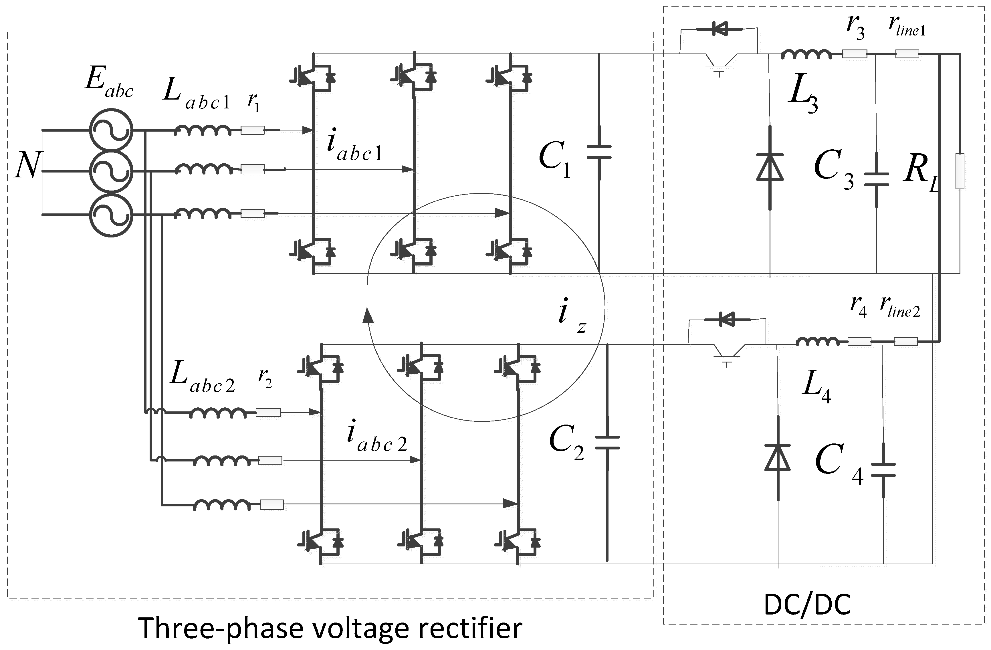
Figure 1 shows the parallel topology of two isolated AC/DC charging modules. The first stage is a three-phase voltage type rectifier, and the second stage is a buck chopper. The AC side is powered by a three-phase 380 V line, and the DC voltage is output through the filter inductor and the three-phase rectifier bridge. The filter capacitors at DC side are C1, C2, in which voltages are adjusted by the buck circuits.
2.2. Mathematical Model Analysis of Zero-Sequence Circulation
The AC side and DC side in the non-isolated AC/DC charging module are connected directly. According to Kirchhoff’s current law (KCL) and Kirchhoff’s voltage law (KVL), the mathematical model of the parallel system in Figure 1 can be written as follows.
where , , are the three-phase grid voltages; , , (n = 1, 2) are the three-phase grid side currents of the two parallel rectifiers; is neutral point voltage; (n = 1, 2) are the duty cycles of the three-phase bridge arm in one switching cycle; are the AC filter inductors; and is the value of the output voltage.
Other definitions are as follows: is the zero-sequence current of rectifier 1; is the zero-sequence current of rectifier 2; and , , . According to d-q coordinate transformation, the above equations can be expressed as:
According to the definition of zero-sequence loop and zero-sequence duty cycle, the above equations can be simplified to:
where .
Therefore, it can be seen that, when two rectifiers are connected in parallel, a zero-sequence circulation path will be generated, resulting in zero-sequence circulation current. If the circulation current is not suppressed well, the system will have a great bad impact such as AC side current waveform distortion. The magnitude of the circulating current is determined by the difference between the zero-sequence duty ratios ( and ) of the two rectifiers.
3. Improved SVPWM Suppression of Zero Sequence Circulation
SVPWM is usually used in the control of the three-phase voltage type rectifier. When SVPWM is used, the zero vector of the three-phase rectifier will change, resulting in a zero-sequence current. The SVPWM control strategy improved by zero vector allocation is the most common method to suppress zero sequence circulation. However, when there are more than two parallel modules, the calculation of zero vector allocation is very complex. Therefore, an improved SVPWM method based on zero-sequence voltage compensation is adopted in this paper, which only needs to calculate its own zero sequence current.
The equivalent circuit diagram of the zero-sequence loop is described as follows.
As seen in Figure 2, the path of the zero-sequence current flow only contains small damping such as the inductance, the parasitic resistance and the line impedance. Therefore, only a small difference between the zero-sequence voltages can lead to large zero-sequence current. According to KVL and KCL, the following equations can be obtained:
where and are the inductances of rectifier 1 and 2; and are the sum values of the parasitic resistance and line resistance of rectifier 1 and 2; and , are the neutral point voltages of the two rectifiers. As can be seen from the above equations, if the zero-sequence voltage difference between the two parallel rectifiers can be adjusted to a value infinitely close to 0, the zero-sequence current between the two parallel rectifiers will be greatly reduced.
According to the principle of SVPWM, the phase modulated wave of each phase in the seven-segment is a saddle-shaped wave. Because it is doped with third harmonic and three times multiple harmonics, and the value of each phase comparator can be expressed by the following equations:
where is the time of each carrier cycle for the maximum voltage vector of SVPWM; and , are the durations of the two adjacent vectors, which occur successively in each cycle. The zero-sequence voltage of the compensation is defined as . Thus, the comparison values of the phase-modulated voltage after zero-sequence voltage compensation are as follows:
The corresponding control block diagram can be expressed as Figure 3:
As shown in Figure 3, the zero-sequence loop suppression needs to sample the zero-sequence current () first, where . By setting the reference value of the zero-sequence current to 0, the zero-sequence loop can finally be suppressed to a small value close to 0 through the PI regulator. The small value is called , the product of by is calculated to obtain the zero-sequence voltage component of the required compensation. A new three-phase modulation amount is obtained by adding the three-phase modulated waves , , and , respectively, to the zero-sequence voltage compensation component, which is then compared with the triangular wave to generate the final control signals , , .
For the rectifier parallel model analyzed above, since the zero-sequence loop path is provided by the parallel rectifiers, when one of the zero-sequence loops is suppressed, the other path of the zero-sequence loop will be blocked. Therefore, when there are N rectifiers working in parallel, it is only necessary to use the zero-sequence loop suppression method for any of the N-1 rectifiers.
4. Consistency-Based Current Sharing Control
The first-stage rectifier of the charger converts the three-phase alternating current of the grid side into the direct current, and the output voltage is regulated by the second-stage Buck circuit to meet the charging demand of the battery. The differences among the output characteristics of the Buck circuits may cause inconsistent output currents among the modules. As a result, the service life of each module becomes unbalanced, so the redundancy of the parallel system is greatly reduced. The control mode of the second-stage Buck circuit adopts a double closed loop control strategy, which is composed of a voltage outer loop and a current inner loop [21].
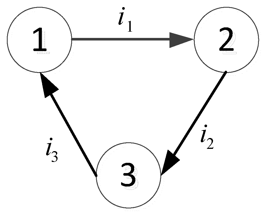
If there are N charging modules in the parallel system, each charging module can be regarded as a communication point that provides current information. The information topology among parallel charging modules can be regarded as a non-connected graph, composed of N current communication points. Set as the current value of the information node , and as the number of the present iteration. In the parallel system, the current value of each communication point is adjusted according to the current output of its adjacent charging modules, and its value is iterated following the current communication with the adjacent charging modules. As the number of the iteration times increases, the output current sharing errors among the parallel rectifiers will become smaller and smaller, eventually reaching uniform convergence or within a small error range. The uniform stacking formula can be expressed as:
where and are the current values of node , in the kth iteration; represents the iteration coefficient; and is the total number of information nodes.
The whole system can be written in the following matrix form:
where is the weight matrix of the communication network.
In the Equation (18), is an N-order unit matrix; is a value which determines the convergence speed; and is the L-value eigenvalue of matrix . Assume that is the initial current value of each communication point, and A indicates a column vector where all the elements are 1. Eventually, the current of all nodes converge to:
5. Simulation and Experiment
In this paper, a parallel system which is composed of three charging modules is built in a MATLAB simulation to verify the validity of the proposed control strategy. The simulation parameters of the charging module are as Table 1.
The simulation analysis and experimental verification of the proposed control strategy are explained in Section 5.1 and Section 5.2.
5.1. Zero-Sequence Circulation Suppression Simulation Results
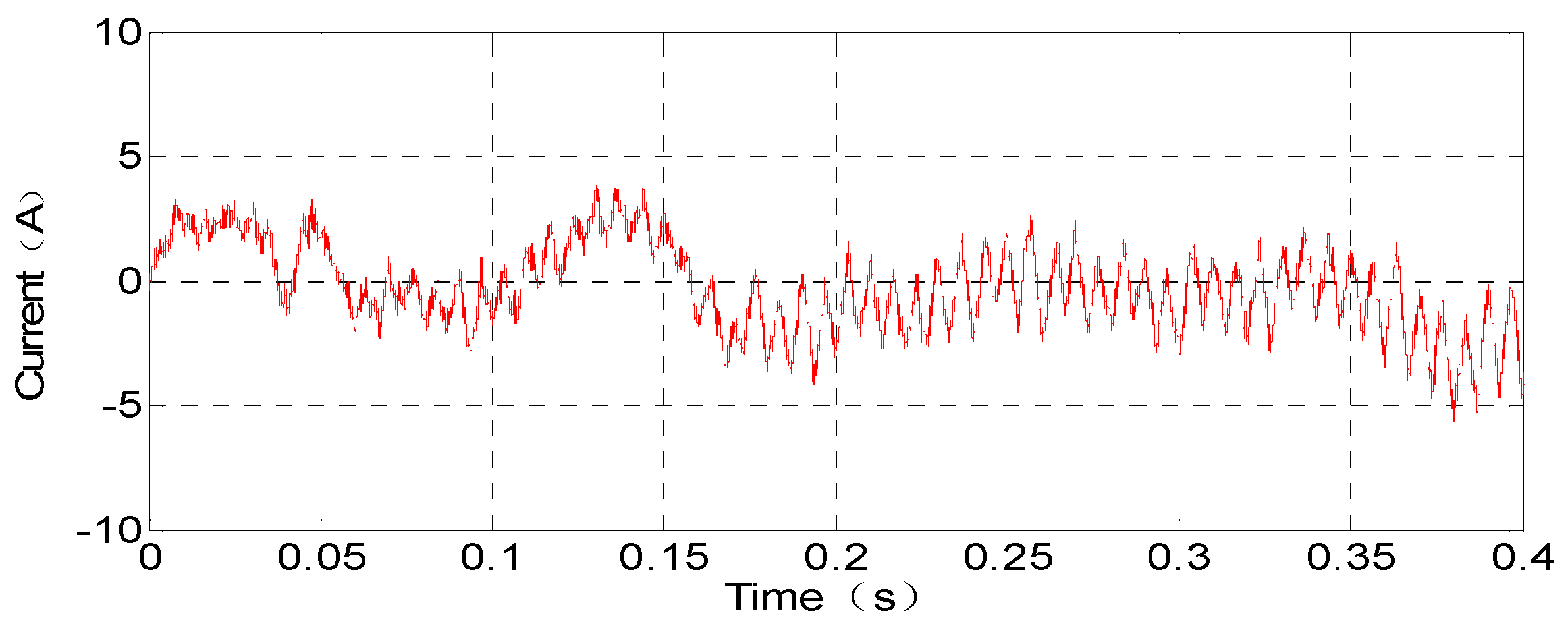
Since the line impedances of the three parallel charging modules are inconsistent, not only will the inconsistent output current occur among the modules connected in parallel, but the zero-sequence circulation will also appear. To solve the above issues, the circulation issue must be first solved, and then the current sharing issue. As shown in Figure 5, the zero-sequence circulation will cause a distortion in the current waveform at the AC side. The magnitude of the zero-sequence loop is shown in Figure 6. The max value is up to 5 A, while the current on the AC side is only 15 A.
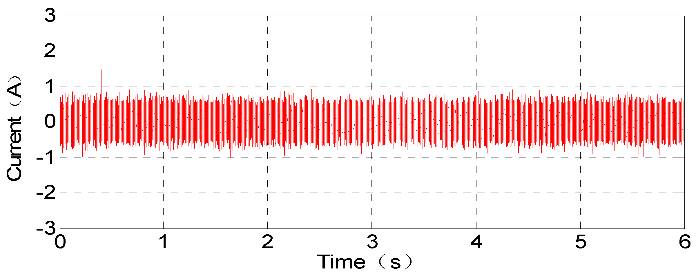
According to the method introduced in Section 3, N charging modules in parallel need only use loop suppression for any N-1 modules. Therefore, only module 1 and module 2 need to suppress the circulation. With the method of compensating zero-sequence voltage component, the zero-sequence circulation current is effectively suppressed. The current waveform distortion at the AC side is significantly reduced, and the harmonics are small as shown in Figure 7 and Figure 8. Meanwhile, at the DC side, the output currents become smoother.
5.2. Current Sharing Simulation Results
For the current sharing errors shown in Figure 9, this paper proposes a current sharing control method based on the consistency algorithm. The main circuit of the charging module is divided into a three-phase voltage rectifier and a DC chopper. The DC/DC circuit adopts voltage and current double closed loop control. Each charging module samples the output DC current, then the consistency algorithm is used, in which the current values of local module and neighbor modules are iterated. The output error value is then superimposed on the outer voltage loop. As shown in Figure 10, the output current of DC2 is transmitted to DC1 through CAN communication for iteration, and the output currents of DC3 and DC1 are transferred to DC2 and DC3 for iteration, respectively. Through the interaction of the current information on the reference voltage terminal, the output voltages are adjusted in real-time to achieve accurate current sharing.
As shown in Figure 11, the output current of each module before 0.4 s has a significant difference, and the output currents are 11.7 A, 9.8 A and 8.5 A, respectively. The calculation equation of the uneven flow rate is:
The uneven flow rate calculated from Equation (21) is 32%. The consistency algorithm starts at 0.4 s. Then, the output currents gradually become uniform, and they are almost the same at 2 s. It can be seen that the proposed method has an obvious current sharing effect and uniform current accuracy. The dynamic response is fast: when the load suddenly increases at 3 s, and a 40 Ω resistor is connected in parallel, the current sharing accuracy of the system is still satisfactory. The proposed method can, not only achieve a very high current sharing performance in a steady state, but also maintain a high current sharing accuracy in a transient state.
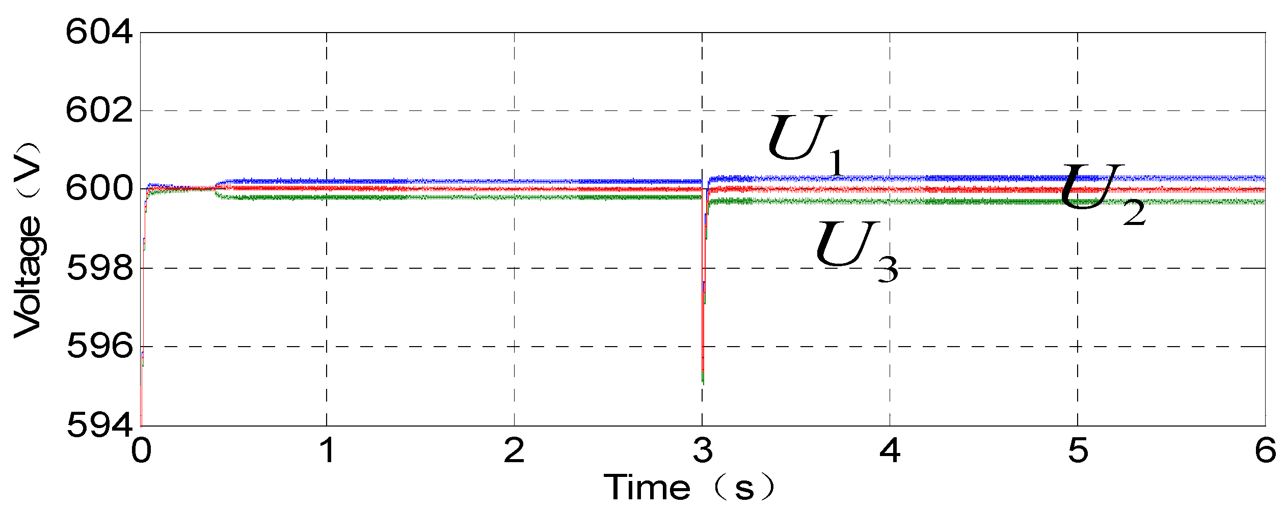
Figure 12 shows the DC output voltages of the three charging modules. The output voltage is 600 V due to the control of the voltage loop before the current sharing measure is taken. Starting the consistency algorithm at 0.4 s, the output voltages of the three modules are 600.2 V, 600 V, 599.8 V. After 3 s, the load suddenly increases, so the output voltages adjust to 600.25 V, 599.75 V, 600 V soon after. Therefore, the method can obtain extremely high voltage accuracy while achieving extremely high current sharing accuracy.
In order to further verify the practicability and effectiveness of the proposed control strategy, the corresponding experimental verification is carried out. The software flow chart of the consistent current sharing algorithm is shown in Figure 13. Charging module 1 is connected in series with 0.1 Ω line impedance, and the series resistance of modules 2 and 3 are 0.15 Ω and 0.2 Ω, respectively. The load impedance is 20 Ω, and the output DC voltage is 400 V. Figure 14 shows the zero-sequence loop generated by the parallel system when the output current is not equal. According to the graph analysis, the AC side currents of the parallel charging modules without the loop suppression method produce different degrees of distortion. After the suppression of the voltage component, the current waveform on the AC side is significantly improved, and the zero-sequence loop is effectively suppressed, the waveform is shown in Figure 15.
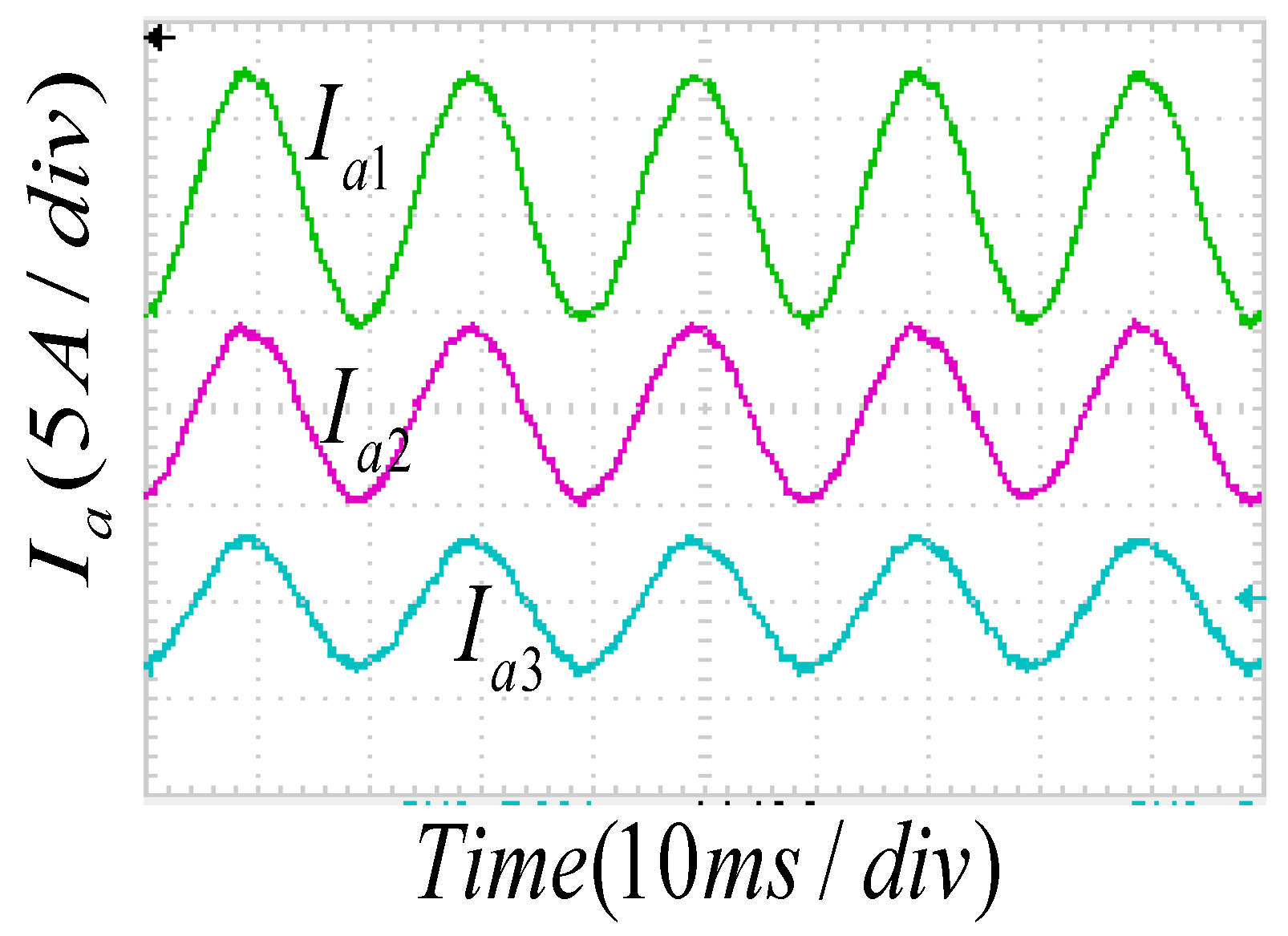
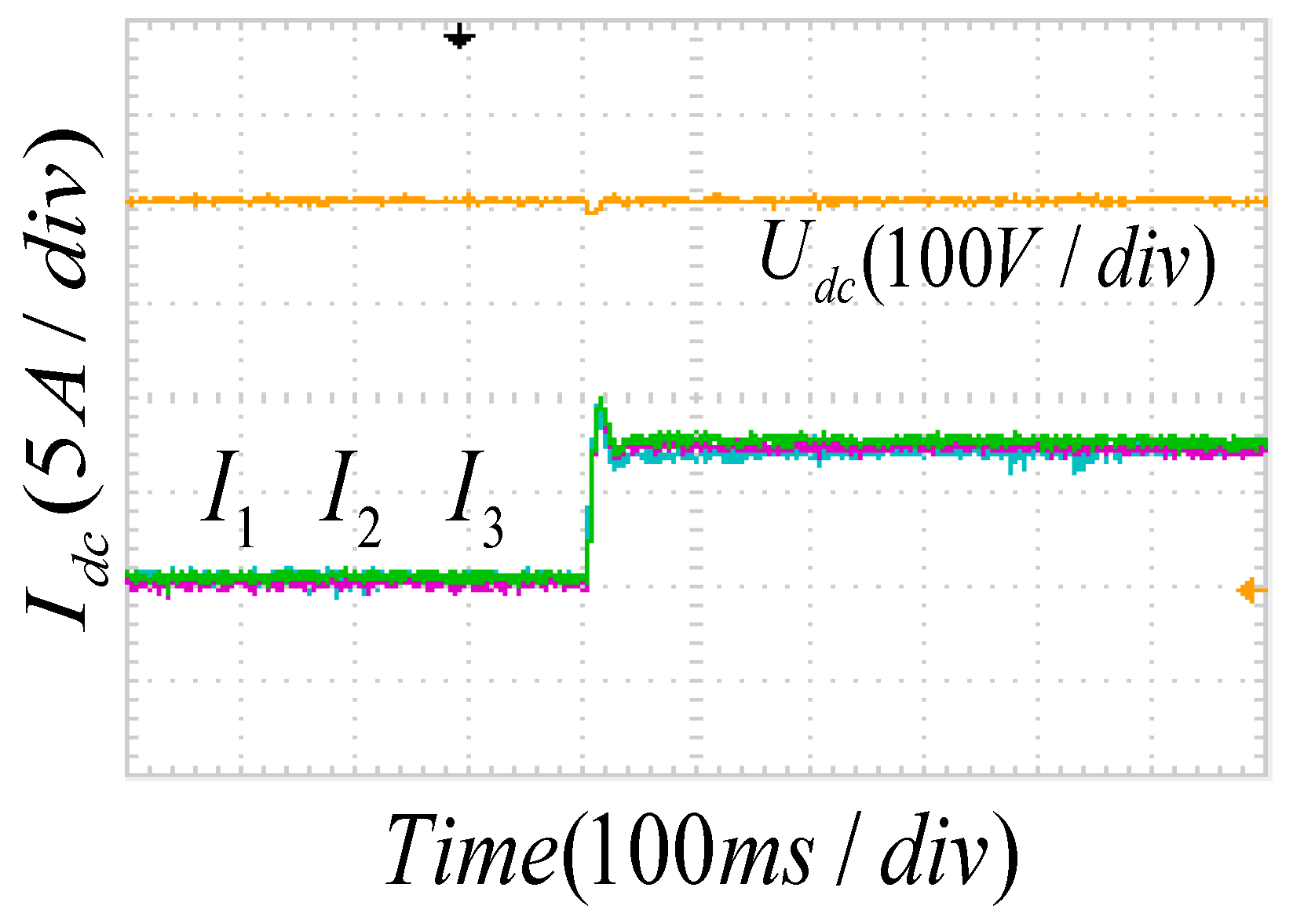
However, due to the different line impedances of the various charging modules, it can be seen from Figure 16 that the output currents are 4.2 A, 6.9 A and 8.9 A. The consistency algorithm starts at 7 s, and CAN communication is used to exchange current information among adjacent rectifiers, in which the communication cycle is 10 ms. The currents of the three modules tend to be consistent after 1.25 s to achieve the current sharing effect. The uniformity of the consistency algorithm not only achieves high-precision current sharing in steady state, but also achieves a good current sharing effect in transient mode. The current waveforms are shown in Figure 17.
6. Conclusions
This paper proposes a SVPWM control strategy based on the compensation of zero sequence voltage and a current sharing strategy based on the consensus algorithm for non-isolated AC/DC charging modules. The main contributions of the paper are as follows:
- Only the zero-sequence circulation current is sampled for feedback control to inhibit circulation, which does not require complex calculation and no communication is required among modules, thus reducing the communication burden.
- Compared with the droop control method, the proposed current sharing control strategy can ensure the voltage accuracy while maintaining the current sharing accuracy.
- Compared with the master–slave control, the proposed current sharing control strategy has no master module or slave module, which greatly increases redundancy.
Finally, the effectiveness of the proposed loop and current sharing control strategies are verified through simulation and experiment results. The proposed method is superior to traditional control strategies and provides an effective solution for the parallel operation of non-isolated AC/DC charging modules.
Additionally, power supply systems, particularly for high power levels, are made of several converters in parallel. Predictive diagnostic can effectively reduce the adverse effects of system failure. But today’s predictive diagnostics usually follow a centralized way instead of a distributed networking way, which is less scalable. This problem can be improved by constructing a sparse communication network with the CAN (Controller Area Network) protocol, which can be the focus of future research.
Author Contributions
Software and writing—original draft preparation, T.W.; Writing—review and editing, Y.Z.; Writing—review and editing, L.X.; Investigation, G.Z.; Investigation, X.Q.
Funding
This research was funded by NSFC, grant number 51807079.
Acknowledgments
Thank you for the technical support of Zhuhui Bai engineer.
Conflicts of Interest
We declare that we have no financial and personal relationships with other people or organizations that can inappropriately influence our work, there is no professional or other personal interest of any nature or kind in any product, service and/or company that could be construed as influencing the position presented in, or the review of, the manuscript entitled, “Parallel Control Method Based on the Consensus Algorithm for the Non-Isolated AC/DC Charging Module”.
References
- Zhang, X.G.; Wang, T.Y.; Wang, X.F.; Wang, G.L.; Chen, Z.; Xu, D.G. A Coordinate Control Strategy for Circulating Current Suppression in Multiparalleled Three-Phase Inverters. IEEE Trans. Ind. Electron. 2017, 64, 838–847. [Google Scholar] [CrossRef]
- Pan, C.T.; Liao, Y.H. Modeling and Control of Circulating Currents for Parallel Three-Phase Boost Rectifiers with Different Load Sharing. IEEE Trans. Ind. Electron. 2008, 55, 2776–2785. [Google Scholar]
- Chen, T.P. Circulating zero-sequence current control of parallel three-phase inverters. IEE Proc. Elec. Power Appl. 2006, 153, 282–288. [Google Scholar] [CrossRef]
- Komatsuzaki, Y. Cross current control for parallel operating three phase inverter. In Proceedings of the 1994 Power Electronics Specialist Conference-PESC’94 Record, Taipei, Taiwan, 20–25 June 1994; pp. 943–950. [Google Scholar]
- Zhang, Z.C.; Ooi, B.T. Multimodular current-source SPWM converters for superconducting a magnetic energy storage system. IEEE Trans. Power Electron. 1993, 8, 250–256. [Google Scholar] [CrossRef]
- Ge, B.G.; Lu, X.; Yu, X.H.; Zhan, M.S.; Peng, F.Z. Multiphase-Leg Coupling Current Balancer for Parallel Operation of Multiple MW Power Modules. IEEE Trans. Ind. Electron. 2014, 61, 1147–1157. [Google Scholar] [CrossRef]
- Liu, L.; Liu, Z.Q.; Chen, Q.H. Research and simulation of circulation current control for grid tied inverters connected in parallel. In Proceedings of the Chinese Control and Decision Conference (CCDC) IEEE Conferences, Yinchuan, China, 28–30 May 2016; pp. 6036–6041. [Google Scholar]
- Ye, Z.H.; Boroyevich, D.; Choi, J.Y.; Lee, F.C. Control of circulating current in two parallel three-phase boost rectifiers. IEEE Trans. Power Electron. 2002, 17, 609–615. [Google Scholar] [Green Version]
- Xing, K.; Mazumder, S.K.; Ye, Z.; Lee, F.C.; Boroyevich, D. The circulating current in paralleled three-phase boost PFC rectifiers. In Proceedings of the PESC 98 Record, 29th Annual IEEE Power Electronics Specialists Conference (Cat. No.98CH36196), Fukuoka, Japan, 22 May 1998; pp. 783–789. [Google Scholar]
- Hou, C.C. A multicarrier PWM for parallel three-phase active front-end converters. IEEE Trans. Power Electron. 2013, 28, 2753–2759. [Google Scholar] [CrossRef]
- Wang, X.H.; Thu, T.; Hoang, G. Fractional-Order Modelling and Control for Two Parallel PWM Rectifiers. 2018 International Federation of Automatic Control. Available online: http://folk.ntnu.no/skoge/prost/proceedings/PID-2018/0004.PDF (accessed on 16 October 2018).
- Mazumder, S.K. A novel discrete control strategy for independent stabilization of parallel three-phase boost converters by combining spacevector modulation with variable-structure control. IEEE Trans. Power Electron. 2003, 18, 1070–1083. [Google Scholar] [CrossRef]
- Mazumder, S.K.; Acharya, K.; Tahir, M. Joint optimization of control performance and network resource utilization in homogeneous power networks. IEEE Trans. Ind. Electron. 2009, 56, 1736–1745. [Google Scholar] [CrossRef]
- Mazumder, S.K. Continuous and discrete variable-structure controls for parallel three-phase boost rectifier. IEEE Trans. Ind. Electron. 2005, 52, 340–354. [Google Scholar] [CrossRef]
- Meng, L.X.; Dragicevic, T.; Guerrero, J.M.; Vasquez, J.C.; Vasquez, J.C. Dynamic consensus algorithm base distributed global efficiency optimization of a droop controlled DC microgrid. In Proceedings of the 2014 IEEE International Energy Conference (ENERGYCON), Cavtat, Croatia, 13–16 May 2014; pp. 1276–1283. [Google Scholar]
- Li, Y.; Fan, L.L. Stability Analysis of Two Parallel Converters with Voltage–Current Droop Control. IEEE Trans. Power Deliv. 2017, 32, 2389–2397. [Google Scholar] [CrossRef]
- Yang, J.; Jin, X.M.; Wu, X.Z.; Acuna, P.; Aguilera, R.P.; Morstyn, T.; Agelidis, V.G. Decentralised control method for DC microgrids with improved current sharing accuracy. IET Gener. Transm. Distrib. 2017, 11, 696–706. [Google Scholar] [CrossRef] [Green Version]
- Ao, J.H.; Wang, Z.; Chen, J.; Peng, L.; Chen, Y. The Cost-Efficient Gating Drivers with Master-Slave Current Sharing Control for Parallel SiC MOSFETs. In Proceedings of the 2018 IEEE Transportation Electrification Conference and Expo, Asia-Pacific (ITEC Asia-Pacific), Bangkok, Thailand, 6–9 June 2018; pp. 1–5. [Google Scholar]
- Borrega, M.; Marroyo, L.; González, R.; Balda, J.L.; Agorreta, J.L. Modeling and Control of a Master–Slave PV Inverter With N-Paralleled Inverters and Three-Phase Three-Limb InductorsMikel Borrega. IEEE Trans. Power Electron. 2013, 28, 2842–2855. [Google Scholar] [CrossRef]
- Li, Q.-Q.; Liu, S.-L.; Xu, H.-S. Research on the maximum current automatic current-sharing control based on DSP. In Proceedings of the 2017 IEEE International Conference on Information and Automation (ICIA), Macau, China, 18–20 July 2017; pp. 1044–1049. [Google Scholar]
- Xiong, L.S.; Zhuo, F.; Wang, F.; Liu, X.K.; Chen, Y.; Zhu, M.H. Static Synchronous Generator Model: A New Perspective to Investigate Dynamic Characteristics and Stability Issues of Grid-tied PWM Inverter. IEEE Trans. Power Electron. 2016, 31, 6264–6280. [Google Scholar] [CrossRef]
- Zhang, H.G.; Kim, S.; Sun, Q.Y.; Zhou, J.G. Distributed adaptive virtual impedance control for accurate reactive power sharing based on consensus control in microgrids. IEEE Trans. Smart Grid. 2017, 8, 1749–1761. [Google Scholar] [CrossRef]
- Guo, F.H.; Wen, C.Y.; Mao, J.F.; Song, Y.D. Distributed secondary voltage and frequency restoration control of droop-controlled inverter-based microgrids. IEEE Trans. Ind. Electron. 2015, 62, 4355–4364. [Google Scholar] [CrossRef]
- Schiffer, J.; Seel, T.; Raisch, J.; Sezi, T. Voltage Stability and Reactive Power Sharing in Inverter-Based Microgrids With Consensus-Based Distributed Voltage Control. IEEE Trans. Control Syst. Technol. 2016, 24, 96–109. [Google Scholar] [CrossRef]
Figure 1.
Non-isolated AC/DC charging module parallel topology.

Figure 2.
The equivalent path of the zero-sequence loop.

Figure 3.
Zero-sequence loop suppression block diagram.

Figure 4.
Block diagram of consistency-based current sharing control.

Figure 5.
Zero-sequence loop suppression measures grid-side current.

Figure 6.
Zero-sequence circulation current.

Figure 7.
Shows the grid side current after taking the loop suppression measure.

Figure 8.
Zero-sequence current after taking loop suppression.

Figure 9.
DC side output current after the loop suppression measure.

Figure 10.
Parallel system communication topology.

Figure 11.
DC side output current after current sharing.

Figure 12.
DC side voltage after current sharing.

Figure 13.
Consistency algorithm CAN communication flow chart.

Figure 14.
No zero sequence loop suppression.

Figure 15.
Zero sequence loop suppression.

Figure 16.
Consistent algorithm current sharing.

Figure 17.
Load spike.


Table 1.
Simulation system parameters.
| Grid line voltage | 380 |
| Grid frequency | 50 |
| Pre-stage rectifier inductor | 4 mH |
| Pre-stage rectifier capacitor | 3000 uF |
| Output DC voltage | 800 V |
| Post-buck circuit inductance | 6 mH |
| Post-buck circuit capacitor | 2 mF |
| The output voltage | 600 V |
| Load impedance | 20 Ω |
| Module 1 line impedance | 0.1 Ω |
| Module 2 line impedance | 0.14 Ω |
| Module 3 line impedance | 0.12 Ω |
| Zero axis Kp | 0.04 |
| Zero axis Ki | 0.2 |
© 2018 by the authors. Licensee MDPI, Basel, Switzerland. This article is an open access article distributed under the terms and conditions of the Creative Commons Attribution (CC BY) license (http://creativecommons.org/licenses/by/4.0/).
Share and Cite
MDPI and ACS Style
Zhu, Y.; Wang, T.; Xiong, L.; Zhang, G.; Qian, X. Parallel Control Method Based on the Consensus Algorithm for the Non-Isolated AC/DC Charging Module. Energies 2018, 11, 2828. https://doi.org/10.3390/en11102828
AMA Style
Zhu Y, Wang T, Xiong L, Zhang G, Qian X. Parallel Control Method Based on the Consensus Algorithm for the Non-Isolated AC/DC Charging Module. Energies. 2018; 11(10):2828. https://doi.org/10.3390/en11102828
Chicago/Turabian StyleZhu, Yixin, Tao Wang, Liansong Xiong, Gaofeng Zhang, and Xin Qian. 2018. "Parallel Control Method Based on the Consensus Algorithm for the Non-Isolated AC/DC Charging Module" Energies 11, no. 10: 2828. https://doi.org/10.3390/en11102828
Note that from the first issue of 2016, this journal uses article numbers instead of page numbers. See further details here.