Energy Evaluation of Multiple Stage Commercial Refrigeration Architectures Adapted to F-Gas Regulation


Department of Mechanical Engineering and Construction, Campus de Riu Sec., Jaume I University, E-12071 Castellón, Spain
*
Author to whom correspondence should be addressed.
Energies 2018, 11(7), 1915; https://doi.org/10.3390/en11071915
Submission received: 28 June 2018
/
Revised: 16 July 2018
/
Accepted: 18 July 2018
/
Published: 23 July 2018
(This article belongs to the Special Issue Refrigeration, Air Conditioning and Heat Pumps: Energy and Environmental Issues)
Abstract
:This work analyses different refrigeration architectures for commercial refrigeration providing service to medium and low temperature simultaneously: HFC/R744 cascade, R744 transcritical booster, R744 transcritical booster with parallel compression, R744 transcritical booster with gas ejectors, R513A cascade/R744 subcritical booster, and R513A cascade/R744 subcritical booster with parallel compression. The models were developed using compressor manufacturers’ data and real restrictions of each system component. Limitations and operating range of each component and architecture were analysed for environment temperatures from 0 to 40 °C considering thermal loads and environment temperature profiles for warm climates. For booster systems, cascade with subcritical booster with parallel compression provide highest coefficient of performance (COP) for temperatures below 12 °C and above 30 °C with COP increases compared basic booster up to 60.6%, whereas for transcritical boosters, architecture with gas ejectors obtains the highest COP with COP increases compared to the basic booster up to 29.5%. In annual energy terms, differences among improved booster systems are below 8% in the locations analysed. In Total Equivalent Warming Impact (TEWI) terms, booster architectures get the lowest values with small differences between improved boosters.
1. Introduction
Commercial refrigeration systems are large contributors to the Greenhouse Effect due to four aspects: large refrigerant charges, high leakage rates, high energy consumption, and use of high GWP refrigerants such as R404A (GWP = 3922) or R507A (GWP = 3985) [1,2]. Europe, leading the fight against the climate change, has adopted a restriction for centralised refrigeration systems in the commercial sector from 1 January 2022 on (Regulation (EU) No 517/2014 [3]). This regulation has limited the GWP of the refrigerant to 150, in multipack centralised refrigeration systems for commercial use with capacity of 40 kW or more, with the exception of the refrigerant for the primary circuit of cascade systems where the GWP limit of 1500 has been considered. To accomplish this restriction, direct expansion in centralised refrigeration systems must rely on refrigerants with GWP less than 150. Among the different possible fluids to be used, the most suitable fluids are R744, HFO synthetic refrigerants and their mixtures, and HC, as it has been studied by members of the British Refrigeration Association et al. [4].
Supermarket refrigeration in Europe was dominated by direct expansion systems with R404A for low and medium temperature [5] and recently by R134a/R744 cascade which was experimentally analysed by Sanz-Kock et al. [6]. However, due to the restrictions established by the F-Gas, some of the existing commercial refrigerating plants will disappear as they cannot be reconverted to completely fulfill the F-Gas Regulation. In many cases, installations will have to modify their technology in order to avoid refrigerants with GWP greater than 150 to direct expansion. One possible solution for the existing systems is to replace the direct expansion systems by secondary fluid loops, such as the ones described by Wang et al. [7]. Nonetheless, the introduction of secondary fluid loops generally introduces penalties in the energy efficiency of the system. Sánchez et al. [8], measured energy increments up to 14.0% when reconverting a R134a/CO2 direct cascade to an indirect one using propylene-glycol at medium temperature. Llopis et al. [9], presented an experimental evaluation of energy consumption reconverting a direct expansion refrigeration system to an indirect system, using R134a and R507A, with energy consumption increases up to 22.8% (R134a) and 38.7% (R507A).
Another possibility for accomplishing the F-Gas Regulation is to use systems whose operation rely on R744 as the main refrigerant. Shecco presented a report [10] of the effect that the F-Gas has on the HVAC&R industry. This report shows the number of supermarkets in Europe using transcritical systems. There were 8732 supermarkets using R744 transcritical systems in 2016, but the most part of them (98.16%) are located in northern countries where the environment temperatures are low or moderate. In cold or moderate regions, the R744 basic booster system is the commonly chosen solution since it is able to provide high energy performance [11], however, in warm regions such as Spain, Italy, or Portugal, the R744 basic booster does not offer an acceptable energy efficiency, thus in the last years, cascade systems with R744 as low temperature refrigerant have been widely used in warm regions due their good performance, but the efforts in recent years have been directed to optimising the performance of booster systems with control strategies [12], to integrate heating and air conditioning [13,14,15], and to improve the refrigeration architecture using advanced R744 booster systems [16] in warm regions.
Some of these improvements are: parallel compression [17] to reduce the mass flow rate of the medium temperature compressor (MTC), mechanical subcooling [18,19] to increase the specific cooling capacity in evaporators, systems with ejectors and parallel compression [20,21] to reduce exergy losses in the expansion processes and the MTC mass flow rate, and overfeed evaporators [22,23] to achieve higher evaporation temperature. In addition, the heating and air conditioning integration in the booster architecture is possible and it is an efficient solution to reduce annual energy consumption as analysed by Karampour et al. [15] and Hafner et al. [24]. Ge et al. [25] analysed a tri-generation using the high rate of heat rejection in CO2 refrigeration systems in supermarkets to provide space cooling or refrigeration and Polzot et al. [26] analyses the energy saving potential using a Water Loop Heat Pump system. Generally, all these improvements try to reduce the power of the MTC or to use the excess thermal energy, however these systems have more inherent complexity and economic cost than an R744 basic booster.
Some researchers analysed the R744 basic booster and cascade system to compare these types of architectures in different regions with different climates. Sawalha et al. [27,28] evaluated theoretically different CO2 centralised system solutions with two- or single-stage compression systems considering the possibility of using flooded evaporators. He compared the systems taking a R404A system and the NH3/CO2 cascade as reference [29] and he concluded that the cascade system is better for hot climates and the two-stage centralised systems with CO2 are better for cold climates. Also, he indicated that the cascade system offers the best results for high temperature environments. Additionally, Fricke et al. [30] contrasted the energy consumption of cascades and booster systems in different climate regions in the USA, concluding that cascade systems obtain the lowest energy consumption in hot regions and booster systems in cold regions, however, current cascades will not be compatible with the F-Gas Regulation if the medium temperature level is served with direct expansion systems with refrigerant GWP greater than 150.
This work aims to energetically and environmentally compare several refrigeration architectures using R744 as the main refrigerant by introducing two new alternative booster arrangements working in subcritical conditions. A detailed thermodynamic analysis is presented for each configuration using a classic R513A/R744 cascade system as reference due to its extensive use in warm regions for centralised commercial refrigeration. The novelty of the analysis makes emphasis on the operational limits of the main components: compressors, expansion valves, and gas ejectors, as well as the limitations of each architecture depending on the environmental temperature. Additionally, the displacement of each compressor and the maximum operating pressure of each configuration are compared and discussed for a medium-size supermarket typically used in Spain and Portugal.
2. Refrigeration Architectures
This section presents the different refrigeration architectures considered in this work. All the architectures provide service simultaneously to medium and low temperature services using high safety refrigerants (A1). All architectures, with the exception of the R513A/R744 cascade, are in agreement with the restrictions established by the F-Gas Regulation. The R513A/R744 cascade (2.1), R513A cascaded R744 subcritical booster (2.5), and R513A cascaded R744 subcritical booster with parallel compression (2.6) always operate in subcritical conditions, either in the R513A cycle or in the R744 cycle. These cycles have been analysed using R513A (GWP = 629) as refrigerant in the high temperature cycle (HT cycle), because it is a drop-in of the widely used refrigerant in that cycle, R134a (GWP = 1430) [2], that offers improvement in COP with a reduced GWP refrigerant [31,32].
On the other hand, the other architectures analysed (basic booster (2.2), booster with parallel compression (2.3) and booster with gas ejectors and parallel compression (2.4)), use R744 as refrigerant, operating both in transcritical or subcritical conditions depending of the heat rejection temperature.
2.1. R513A/R744 Cascade Cycle (CC)
Cascade configuration, shown in Figure 1, has two independent refrigerant circuits coupled through the cascade heat exchanger (CHX). It uses R513A in the high temperature (HT) circuit and R744 in the low temperature (LT) circuit. It incorporates an internal heat exchanger (IHX) before the LT compressors (LTC) to ensure the expansion of liquid in the expansion valves and a small superheating before LTC, it also incorporates a desuperheater at the discharge of the LTC [33] to perform heat rejection before the cascade heat exchanger. This system was analysed theoretically by Llopis et al. [34] and investigated experimentally by Sanz-Kock et al. [6] with R134a as HT refrigerant as a solution to commercial refrigeration in warm climates. On the other hand, this architecture was also analysed with different A3 refrigerants by Sachdeva et al. [35].
2.2. Basic Booster (BB)
The basic booster configuration, Figure 2, uses only R744 as refrigerant. It incorporates LT compressors, desuperheater (DSH), MT compressors (MTC), a high pressure control valve (HPCV) to control the heat rejection pressure in order to operate in optimal conditions, a flash gas valve (FGV), and a gas-cooler/condenser (GC/K) which needs to be well designed and controlled as analysed by Ge et al. [36] and Tsamos et al. [37,38]. R744 is distributed to the services using direct expansion systems. R744 is sent as saturated liquid to the MT cabinets and subcooled (due to IHX) to the LT cabinets. This system will operate in subcritical or transcritical mode depending on the environment temperature (Section 3).
2.3. Booster with Parallel Compression (BB + PC)
The booster with parallel compression configuration, Figure 3, uses the same architecture as the basic booster (BB) but it includes additional compressors denoted as parallel compressors (PC). The PC extracts saturated vapour from the flash tank and it is compressed to the high rejection pressure. As analysed theoretically by Sarkar et al. [39] in a simple stage, the use of PC allows one to reduce the pressure in the flash tank and to increase the specific cooling capacity. In addition, these compressors reduce the mass flow rate in MT and LT services and in the LTC and MTC. Chesi et al. [40] also analysed this cycle, reaching COP improvements of over 30% with respect to the basic cycle and showed three main parameters with high influence on the cycle; compressors volumetric flow ratio, intermediate pressure, and the separator efficiency. BB + PC but without DSH was theoretically investigated by Gullo et al. [17], who indicated that it allows COP increments compared to the basic booster system up to 33% for an environment temperature of 35 °C. Another study by Tsamos et al. [41] showed that parallel compression is an energy efficient system for moderate and warm climates.
2.4. Booster with Parallel Compression and Gas Ejectors (BB + PC + GEjs)
The booster system with gas ejectors and parallel compression, Figure 4, incorporates ejectors in combination with parallel compressors. Ejectors reduce the mass flow rate through the medium temperature compressors [42] and reduce the exergy losses incrementing the specific cooling capacity in the evaporators.
If the ejector is modulating, it could also replace the high pressure control valve of the system [21]. The use of ejectors in the R744 booster is one of the improvements with better future prospects, such as the multi-ejector system as presented by Hafner et al. [20] and by Hafner and Banasiak et al. [43].
Operation of the ejectors depends mainly on the input pressures and mass flow ratios, as analysed by Li and Groll et al. [44] and Liu and Groll et al. [45] and on the ejectors geometry as evaluated by Liu and Groll et al. [46]. Accordingly, the improvements using ejectors are very dependent on the operating conditions of the system. Nonetheless, this architecture presents COP increments respect to the booster system with parallel compression up to 7%, as analysed by Haida et al. [42].
2.5. Cascade with Subcritical Booster (CC + SB)
The next configuration is a cascade cycle, with R513A in the primary cycle (HT cycle) and a R744 subcritical booster (Figure 5). This system joins two types of architectures (cascade and booster) to obtain great performance at low and high environment temperatures, because basic boosters architecture have great performance at low environment temperatures, as does the cascade architecture at high environment temperature.
This architecture provides service simultaneously to MT and LT appliances (Section 2.2) with R744, such as the other R744 transcritical boosters, but in this case, the R744 booster always works in subcritical conditions (forced by the HT cycle).
Since MTC always work in subcritical conditions, subcritical R744 compressors can be used in this rack. The advantage is that subcritical compressors present higher efficiencies than transcritical ones operating in subcritical conditions according to the manufacturer-provided data. For this reason, the type of compressors selected for MTC in this architecture are subcritical. This is an advantage in relation to transcritical boosters working in subcritical conditions.
Another advantage of this architecture for some supermarkets with HFC/R744 cascades (widely used in warm climates), if the facility has not reached its end-life use, some parts of the existing system (condenser and HT compressors) could be used in the reconversion procedure.
This system can operate with other refrigerants in the HT cycle such as R152a, R290, and R1270, but these are not considered in this work due to their lower safety classifications.
2.6. Cascade with Subcritical Booster and Parallel Compression (CC + SB + PC)
The last configuration is similar to the previous one but uses parallel compression (PC) (Figure 6). This system corresponds to a cascade cycle with R513A in the primary cycle, maintaining the R744 booster with parallel compression in subcritical conditions. As in the previous case, this system can reuse the HT compressors and condenser of a previous cascade architecture.
For CC + SB + PC, MTC always work in subcritical and now also the PC, so these compressor racks are composed of subcritical R744 compressors.
3. Thermodynamic Modelling and Component Limitations
This section describes the thermodynamic models of each refrigeration cycle component, establishes the transition methodology between operation in transcritical and subcritical conditions, describes the reference supermarket application for sizing the systems, and shows the working limitations of each element that condition the operating of the systems.
3.1. Heat Rejection Characteristics
For R513A cycles, condensing temperature is evaluated with Equation (1), considering an environment-condensing temperature difference (ETD) of 5 K [35].
For R744 cycles in subcritical conditions, condensing temperature is computed with Equation (2), considering an approach temperature (ETD) and a subcooling degree in condenser (Sub). The approach temperature between the condensation and environment temperature has been fixed to 5 K too. On the other hand, a subcooling of 2 K has been considered because the proper operation of this system relies on a certain subcooling degree, as described by Danfoss [47].
For R744 cycles in transcritical conditions, the gas-cooler outlet temperature is calculated with Equation (3), considering an approach temperature of 2 K due to the high thermal effectiveness of the gas-cooler in transcritical conditions, as measured by Sánchez et al. [48]. For these systems, the results are expressed for the optimum heat rejection pressure, which is evaluated through an iterative method.
3.2. Cascade Heat Exchanger (CHX)
The architectures with R513A in an HT cycle has been analysed considering a temperature difference of 5 K between the R744 condensation level and the R513A evaporation level, which it is an average value measured by Sanz-Kock et al. [6] in an experimental cascade plant.
3.3. Desuperheater (DSH)
Although not generally considered in R744 booster systems, we include a DSH in all the cycles, placed at the exit of the LTC, since the compressor’s discharge temperature is always higher than the environment temperature. This desuperheater performs heat rejection before the second compression stage, thus reducing the temperature at the MTC inlet. This element always increases the energy efficiency of the plant. This improvement was analysed by Sanz-Kock et al. [6] in a cascade system. It has been evaluated that the introduction of a desuperheater after the first compression stage reduces energy consumption around 3–4% for each system analysed.
The outlet temperature of R744 at the DSH is evaluated with Equation (4), considering an approach of 5 K (ETD) with the environment temperature (Tenv).
3.4. Refrigeration Heat Loads
All the refrigeration architectures have been evaluated considering the same heat load design condition, which represents a medium-sized supermarket working at standard evaporating levels [49], with cooling capacity of 41 kW and 140 kW for low and medium temperature service, respectively.
The heat load profile considered for all architectures only takes into account variations of the heat load factor between the opening and closing schedule of the supermarket, since they are always maintained at a constant inner temperature. One hundred percent heat load factor has been considered from 7:00 a.m. to 10:00 p.m. and 50% from 10:00 p.m. to 7:00 a.m. for every day of the year.
All the data described above is summarised in Table 1.
3.5. Internal Heat Exchanger (IHX)
The compressor manufacturer specifies a minimum lubricant working temperature to operate with suitable viscosity [50]. Accordingly, it is necessary to introduce an IHX in the suction line of the LT compressors. This element ensures liquid refrigerant at the inlet of the expansion valve (increasing the specific cooling capacity in evaporator) and it allows increasing the refrigerant temperature at the compressors inlet. The combination of both effects provides a small energetic improvement to the system as discussed by Llopis et al. [51]. Taking into account the experimental results from the reference, a constant thermal effectiveness of the IHX of 65% has been considered for all the refrigeration architectures.
3.6. Compressors
Compressors used in this study have been modelled using data from manufacturer BITZER. Models are based on parametric adjustments of the volumetric and global efficiencies as detailed by Equations (5)–(7), whose coefficients are presented in Appendix A. Equation (6) expresses the global efficiency for all the compressors except MTC in subcritical conditions, for which the global efficiency is modeled by Equation (7), because it get a smaller error than with Equation (6). More information about these expressions in a hermetic compressor can be found in Sanchez et al. [52].
In the architectures, there are two types of compressors (subcritical and transcritical). In addition, the transcritical compressors can work in both transcritical and subcritical mode. The compressors chosen for LTC for all systems are subcritical compressors.
The MTC and PC chosen for transcritical boosters (BB, BB + PC, BB + PC + GEjs) are transcritical compressors and they can operate in transcritical or subcritical mode, thus these compressors are modelled with different equations depending on their operating mode. The MTC and PC chosen for subcritical boosters (CC + SB, CC + SB + PC) are subcritical compressors and they can operate only in subcritical mode, thus these compressors have better efficiency in subcritical mode than transcritical compressors working in subcritical mode.
3.7. Ejectors
To model the architecture operating with gas ejectors, the thermodynamic model described by Liu and Groll et al. [45] has been taken as reference. It considers the mass, movement, and energy conservation equations in each ejector part. The behaviour of each part has been modelled considering a constant efficiency of 0.8 in the motive nozzle, suction nozzle, and diffuser, as recommended by Elbel and Hrnjak et al. [53]. In addition, a constant mass entrainment ratio (ratio of suction mass flow rate respect to motive mass flow rate) of 0.25 has been considered, as an average value of mass entrainment ratios analysed by Banasiak et al. [54], for the entire operating range.
3.8. Components’ Operating Restrictions
To be as close as possible to reality, the real elements’ operating restrictions have been included in the analysis of the refrigeration architectures to evaluate their energy performance over a wide range of environment temperatures.
The most important operating restrictions are:
- -
- A minimum pressure difference (ΔP) of 3.5 bar is needed in all the expansion valves for proper operation and regulation [55].
- -
- The maximum ΔP in the expansion valves is 35 bar, for proper operation and regulation [56].
- -
- Compressors must always operate with a compression ratio (t) higher than 1.5, because at lower values the compressors can be damaged [57].
- -
- Pressure at the inlet of the PC must always to be lower than 55 bar. This is a restriction from the compressors manufacturer.
3.9. R744 Flash Tank Pressure
The flash tank has a maximum and minimum pressure limitation. The minimum pressure limitation is needed to keep a minimum pressure differential at the expansion valves. Although a minimum pressure differential around 3.5 bar is needed in all the valves for proper operation [54], in a transcritical booster, the minimum flash tank pressure considered is approximately 5 bar higher than the pressure of the medium temperature loads [58]. Thus, for the evaporation temperature of −6 °C (≈30 bar), the minimum flash tank pressure considered will be 35 bar. This limitation is considered for all booster system analysed.
The maximum pressure in the flash tank is limited by the maximum operational pressure difference (MOPD) of the LTEV (35 bar) [56]. Thus, for a low temperature evaporation of −32 °C (≈13.5 bar), the maximum flash tank pressure will be 48.5 bar. A similar restriction was considered by Pardiñas et al. [59].
For booster cycles without PC but with flash gas (BB and CC + SB), the receiver pressure will be kept constant at 35 bar because it has been proven that the system COP increases with lower receiver pressure. Ge and Tsou et al. [60] reached the same conclusion for a booster without PC. On the other hand, it has been proven that for booster cycles with PC (BB + PC, BB + PC + GEjs, and CC + SB + PC), the COP is not always higher with lower pressure in the receiver, mainly due to the variable efficiency of the compressor depending on the operating conditions. For this reason, the receiver pressure at architectures with PC can vary between both pressure limitations considered in systems with PC (35–48.5 bar). In addition, it has been proven that for the system with ejectors, the pressure of the receiver also depends on the efficiency of the ejectors, mass entrainment ratio, and the pressure of the gas-cooler, although the receiver pressure limitation will be the same (35–48.5 bar). Flash tank limit pressures for all systems analysed are summarised in Table 1.
3.10. Transition Zone
For transcritical booster architectures, transition between transcritical and subcritical conditions depends on the control algorithm implemented in the regulation device [61]. Figure 7 shows an example of this regulation.
Figure 7a shows the variation of the GC/K output point according to the different operating conditions, while Figure 7b shows the COP variation of the analysed configuration respect to the GC/K heat rejection pressure.
According to Figure 7, the systems operating in transcritical-subcritical regime have three operating zones: transcritical zone, subcritical zone, and transitional zone. The transitional zone marks the progressive transition between the two other zones, to avoid sudden changes in the operation conditions of the booster.
The operation of the system in one zone or another is conditioned by the heat rejection temperature and the desired operating condition. For all the configurations analysed in this work, the maximum COP condition has been chosen for each of the dissipation temperatures. Thus, in transcritical operation, the maximum COP depends on the optimum pressure and its operating conditions. However, in subcritical operation, the maximum COP corresponds to the minimum operating pressure, which depends on the environment temperature, the efficiency of the GC/K, working as condenser, and the subcooling considered. The transition from one zone to the other implies a compromise between getting the maximum COP and a stable operation of the booster, since although the maximum COP is not achieved, the installation has a stable operation in the transition from transcritical to subcritical.
In Figure 7, for environment temperatures above 28 °C, the system follows the transcritical operation curve (line 1) with optimum GC/K pressures above the critical point. For an environment temperature about 28 °C, the optimum COP is obtained at R744 critical pressure (Point A). At this point, for lower environment temperatures, the maximum COP is achieved by keeping the GC/K pressure in transcritical operation until it reaches an environment temperature in which the system COP equals the transcritical one (Point B) as in subcritical operation (Point C). For lower environment temperatures, the highest COP is obtained with the system in subcritical operation (line 2).
In order to avoid a sudden change from transcritical (point A) to subcritical operation (point C), GC/K pressure and subcooling must be varied progressively (line A–C). Thus, the booster system operates stably but with little COP reduction.
3.11. Architectures’ Working Cycles
The introduction of these restrictions to the refrigeration architectures, limit the operation of some components of the refrigeration systems over all the range of environment temperatures that they need to cover. The consequence is that a defined architecture will operate with a different cycle all over the environment temperature range, as summarised by Figure 8 and detailed for each cycle architecture in the following subsections.
3.11.1. R513A/R744 Cascade System (CC)
With the considered limitations for the expansion valves (ΔP ≥ 3.5) and compressors (t ≥ 1.5) (Section 3.8), the cascade system operates in the R513A cycle with floating condensing pressure for outdoor air temperatures higher than 13.7 °C. For lower temperatures, the condensing pressure is maintained at 5.9 bar (18.7 °C) in order to guarantee the proper operation of the R513A expansion valve (ΔP = 3.5).
3.11.2. R744 Basic Booster (BB)
As can be seen in Figure 8, the R744 basic booster cycle operates in four zones: optimised transcritical cycle for outdoor air temperatures higher than 27.9 °C (TRANSC); transition zone (TRANSI) from 27.9 °C to 23 °C as described in Section 3.10; subcritical zone (SUB) with floating condensing pressure from 23 °C to 2.4 °C; and finally, subcritical zone maintaining the condensing pressure of the heat rejection at 44.5 bar (9.4 °C), to avoid compression ratios lower than 1.5. The compression ratio restriction for the MTC is more restrictive than the minimum ΔP at the medium temperature expansion valve (MTEV).
3.11.3. R744 Booster + PC (BB + PC)
The R744 booster system with parallel compression (PC) operates similarly to the basic booster (transcritical, transition, and subcritical), but operating with the PC for outdoor air temperatures higher than 9.3 °C. Below this temperature, the compression ratio of the PC reaches 1.5, so the heat rejection pressure is kept constant at 52.5 bar (tPC = 1.5). For temperatures below 8.6 °C, the COP of the BB + PC is lower than the BB, therefore, below this outdoor air temperature, the PC is disconnected and the system starts operating as BB, thus, from 8.6 °C to 2.4 °C, the refrigerating plant operates as a BB with floating condensing pressure, and below 2.4 °C, the heat rejection pressure is kept constant at 44.5 bar to avoid a compression ratios in MTC lower than 1.5.
3.11.4. R744 Booster + PC + Gas Ejectors (BB + PC + GEjs)
The R744 booster system with gas ejectors and parallel compression operate in transcritical, transition, and subcritical conditions for outdoor air temperatures higher than 18.5 °C. At this temperature (18.5 °C), the flash tank pressure reaches 35 bar, so, from 18.5 °C to 18 °C, the GC/K pressure is kept constant at 65.2 bar. Below 18 °C, the COP of the BB + PC + GEjs is lower than the BB + PC, therefore, below this environmental temperature, the GEjs are disconnected and the system starts operating as BB + PC, thus for lower outdoor air temperature, the operation is the same as described for the BB + PC.
3.11.5. R513A Cascade + R744 Subcritical Booster (BB + SB)
The R513A cascade with R744 subcritical booster operates with floating condensing pressure at the HT cycle for outdoor air temperatures above 21 °C. At this temperature (21 °C), the ΔP in the HT expansion valve is of 3.5 bar, so, below this value, the HT condensing pressure is kept constant at 7.3 bar. From 21 °C to 20 °C, the pressure of the HT condenser is kept constant but for lower temperatures than 20 °C, the COP of the BB is greater than the BB + SB, therefore, below 20 °C, the facility operates as a R744 basic booster as previously described.
3.11.6. R513A Cascade + R744 Subcritical Booster + PC (BB + SB + PC)
The R513A cascade with R744 subcritical booster and parallel compression operates with floating condensing pressure at the HT cycle for outdoor air temperatures above 23.8 °C. At this temperature (23.8 °C), the compression ratio of the parallel compressors is lower than 1.5, and consequently the dissipation pressure of the R513A cycle must be kept constant at 7.9 bar. The limit in this case occurs at higher environment temperatures (23.8 °C) than the previous architecture because the use of the parallel compression raises the R744 condensing level to avoid a compression ratio of PC lower than 1.5. So, from 23.8 °C to 22.9 °C, this system operates like a cascade with fixed condensing pressure at the R513A cycle. For outdoor environmental temperatures below 22.9 °C, the COP of the BB + SB + PC architecture is lower than that of BB + PC, the R513A cycle is disconnected, and the system starts working as a booster with parallel compression (BB + PC) as described previously.
3.12. Other Considerations
In addition to the specific limitations considered in each architecture, the following considerations and assumptions are taken to obtain the energy results of all the configurations:
- -
- Heat rejection pressures: the evaluation of the energy efficiency of each architecture is computed at the optimum heat rejection pressure corresponding to the pressure that maximises COP.
- -
- Pressure drops and heat losses with environment are neglected.
- -
- The ejectors are modelled as if they operated at maximum efficiency throughout the temperature range analysed.
- -
- The motive and secondary flows have the same pressure at the ejectors mixing zone inlet.
- -
- Kinetic energy at the inlet and outlet of the ejectors are considered as negligible.
- -
- All the thermo-dynamic properties were evaluated using Refprop 9.1 [62] and all architectures are modelled with Matlab (2016b, Mathworks, USA) and VBA (2016, Microsoft, USA).
4. Results and Discussion
This section is devoted to presenting the results of the performance evaluation of all the architectures presented in Section 2. The systems are evaluated using the models and assumptions detailed in Section 3 for a range of environment temperatures from 0 to 40 °C.
The first part is dedicated to analysing the COP and capacity over the whole environment temperature range. For this range, the emphasis is on the evaluation of the compressor displacements and the optimum operating pressures. The second part is devoted to presenting the energy consumption of the systems with the conditions summarised in Section 3.4 in several representative cities of Spain and Portugal.
4.1. COP
The COP evolution for each refrigeration architecture, evaluated with Equation (8), over the range of environment temperatures is presented in Figure 9. The COP values are the optimum at each outdoor air temperature, considering optimised heat rejection pressure and working cycle according to Figure 8.
Compressor power is calculated using Equation (9).
As it can be observed in Figure 9, for environment temperatures above 14 °C, R513A/R744 cascade (CC) presents the highest COP among all the configurations with a significant COP increase compared to transcritical boosters. However, for environment temperatures below 12 °C, all booster architectures present higher COP in relation to CC. This is mainly because at low environment temperatures, the high temperature cycle of the cascade is forced to condensate at a fixed pressure to avoid small pressure differentials in the HT expansion valve, as analysed in Section 3.8.
On the other hand, basic booster has the lowest COP of the booster systems for the whole range of analysed temperatures, but for outdoor air temperatures below 9 °C, all transcritical boosters (BB, BB + PC, and BB + PC + GEjs) have identical COP because for temperatures lower than 9 °C, these systems operate as BB, however, the subcritical boosters (CC + SB and CC + SB + PC) have higher COP than any other system analysed for temperatures below 12 °C for CC + SB and below 14 °C for CC + SB + PC. This is mainly due to the fact that these two systems use subcritical compressors which have better performance than transcritical ones working in subcritical condition. For all booster architectures, for environmental temperature of 2.4 °C, the limitation of the minimum compression ratio at MTC is achieved, so below this temperature, the rejection pressure in the R744 cycles is kept constant.
For outdoor air temperatures between 14 and 30 °C, all improved boosters have similar COP but with an important COP improvement compared to the BB, mainly for temperatures above 20 °C. For high environment temperatures (above 30 °C), the COP differences increase between R744 boosters, with the CC + SB + PC architecture having the highest COP, followed by CC + SB with a similar COP, then the BB + PC + GEjs, BB + PC, and finally the BB.
The COP differences between each architecture compared to the R513A/R744 cascade (CC) and R744 basic booster (BB) are presented in Figure 10 and Figure 11, respectively, and summarised in Table 2. The COP variations are obtained with Equations (10) and (11).
In relation to the R513A/R744 cascade, all booster architectures present COP improvements for environment temperatures from 0 °C to 12 °C. On the one hand, these improvements range from 48% to 0% for transcritical boosters (BB, BB + PC, and BB + PB + GEjs) with hardly any difference between them. Accordingly, these booster improvements are not justified for temperatures below 12 °C. On the other hand, cascaded subcritical boosters (CC + SB and CC + SB + PC) have a COP improvement in relation to CC from 56% to 0%, with a small COP improvement over the BB up to 5.4–7.3% for environment temperatures from 0–12 °C.
However, for temperatures above 14 °C, the COP of all booster architectures falls below that offered by the R513A/R744 cascade. The reductions in COP in relation to the R513A/R744 cascade solution vary from 0 to 41.5% for the BB, from 0 to 29.3% for the BB + PC, and from 0 to 24.3% for BB + PC + GEjs, whereas the reductions of cascaded R744 subcritical boosters are small; for the CC + SB architecture, the reductions vary from 0 to 7.4% and for the CC + SB + PC from 0 to 6%. These COP variations of each architecture with respect to the BB and CC are summarised in Table 1.
In booster architectures, improved transcritical boosters get COP increments over the BB, for outdoor air temperatures above 8.6 °C, up to 20.8% for BB + PC and up to 29.4% for BB + PC + GEjs, however, cascaded subcritical boosters have COP increments from 1.6 to 58.2% for CC + SB and from 5% to 60.7% for CC + SB + PC with respect to BB for whole range of temperatures analysed.
4.2. Displacement of Compressors
In this subsection, the displacement of each type of compressor rack and its variation range is presented and discussed for all the environment temperatures. This parameter allows one to select the number and the size of the compressors to be installed at the refrigerating facility. Calculations are made considering refrigeration heat loads for MT and LT established in Section 3.4. The results of the range of displacement calculated for each compressor rack are analysed graphically in the next figures (summarised in Table 3).
The displacement of the compressors are related to the volumetric efficiency, mass flow rate, and the density of the refrigerant in the suction side. The displacements for the compressors are obtained using Equation (12).
The next table presents the maximum and minimum compressor displacements, as well as their variation over the environment temperature range from 0 to 40 °C. Each compressor’s rack for each architecture is denoted by a letter and a number to be easily identified in the graphs. The ranges of displacement shown in Table 2 are an output result of the computation model.
4.2.1. Low Temperature Compressors (LTC)
The LTC use R744 as refrigerant and the displacement for each architecture, all over the environment temperature range, is presented in Figure 12. For this compressor rack, BB + PC gets the largest displacements because the flash tank optimum pressure increases for higher outdoor air temperatures, so the enthalpy increment in LTE is reduced and, for the same cooling capacity, the mass flow rate through LTE and LTC increases. The same happens with the other systems with parallel compression (BB + PC + GEjs and CC + SB + PC).
For this type of compressor, the differences between all architectures are smaller, with a maximum displacement variation from 0 to 40 °C of ±7.6% for BB + PC, for a fixed cooling capacity of 41 kW.
Other architectures have similar LTC displacement in the whole range of temperatures because the conditions before and after the LTE are similar. In R513A/R744 cascade, the HT cycle forces the R744 cycle to work in similar conditions, and for R744 boosters without PC, the flash tank keeps a constant pressure of 35 bar.
For outdoor air temperatures above 23 °C, the CC + SB + PC operates with the minimum pressure in the flash tank (35 bar) like architectures without PC, because this system is limited by the compression ratio of the PC when operates with R513A cycle. For lower temperatures, the R513A compressor of the HT cycle is disconnected and this architecture works as SB + PC with a slight difference in displacement compared to the compressors A2 used in BB + PC architecture, because these architectures operate with a different model of compressors.
4.2.2. Medium Temperature R744 Compressors (MTC)
MTC displacement for each booster architecture is presented in Figure 13 for the entire environmental temperature range. The MTC with larger variation of displacement corresponds to the BB system (B1), with a maximum displacement of 94 m3·h−1 and a minimum of 42.2 m3·h−1. This represents a displacement variation of 38.1%. However, improved boosters allow reductions in the MTC displacement between 38% and 73% compared to the BB, where a booster with ejectors is the system with greatest displacement reduction. For this rack of compressors, due to their displacement variations, it is necessary to use variable frequency drives in order to satisfy the cooling demand. This affects the final cost of the architectures.
4.2.3. R744 Parallel Compressors (PC)
Parallel compressor displacements are presented in Figure 14. As can be observed for the three configurations, the range of displacement needed to cover the entire operating range (0–40 °C) is 60.9% for BB + PC system, 79.9% for BB + PC + GEjs, and 24% for PC. These large variations in displacement are important because, according to the compressor’s manufacturers, the maximum variation range is generally ±40% [49]. For transcritical boosters with PC (BB + PC and BB + PC + GEjs), the variation range will force one to design the parallel compression rack using more than one parallel compressor if the facility is designed for outdoor air temperatures between 8.6–40 °C. Otherwise, for a subcritical booster (BB + SB + PC), this variation can be absorbed by only one compressor.
4.2.4. R513A Compressors
R513A compressor displacements for CC, CC + SB, and CC + SB + PC are detailed in Figure 15. It needs to be mentioned that the displacement of these compressors is of another magnitude than of the R744 ones due to the different specific volumes of R513A. The first observation that can be made is that the CC systems need practically double displacement compared to the configurations of cascaded R744 subcritical booster systems. That is because the R744 condensing level with the cascade is lower than in the other systems. In addition, the variation range of displacement for this configuration remains below 20.9% in all environments. It is important to clarify that the refrigerant R513A is more expensive than R744, so this affects to the final cost of the cascaded systems, although R744 compressors are more expensive than these.
4.3. Maximum Operating Pressures
Another important aspect to be mentioned regarding the refrigeration architectures corresponds to the maximum operating pressures, which condition the classification of the plant regarding safety. Figure 16 presents the optimum working pressures of all the compressors in all the environment temperature range, and Table 4 collects their maximum operating pressures. As it can be observed, the range of pressure needs to be considered. First, the transcritical boosters (BB, BB + PC, BB + PC + GEjs) present maximum operating pressures in the evaluated range near 100–106 bar. Next, the cascaded R744 subcritical booster systems present a maximum working pressure below 67–72 bar. Finally, the cascade solution has a maximum R744 working pressure below 35 bar.
4.4. Annual Energy Consumption (AEC)
This section presents the annual energy consumption of the different analysed refrigeration architectures for some representative cities of Spain and Portugal. The outdoor air temperatures for each city are obtained using the EnergyPlus tool [63] to simulate the systems’ hourly performance.
The energy consumption over 24 h throughout an entire year represents the estimated energy consumption of the refrigeration system for supplying the refrigeration loads detailed in Section 3.4. The heat load profile of the systems always considers the inside of the supermarket to be at the same conditions, since they are air-conditioned, and only takes into account a different heat load factor (LF) depending on the opening or closing schedule of the supermarkets. In this case, 100% heat load factor has been considered from 7:00 a.m. to 10:00 p.m. and 50% from 10:00 p.m. to 7:00 a.m. for all the days of the year. The COP of each refrigeration architecture has been considered at its optimum conditions, those detailed in Figure 9. The annual energy consumption for each location is calculated using Equation (13).
Figure 17 represents the annual energy consumption of each architecture for each location, as well as their average annual temperature, and Figure 18 represents the energy consumption variation of each one, calculated by Equation (14), in relation to the R513A/R744 cascade configuration, which is considered as a reference system in warm climates.
From the results presented in Figure 17, the following inferences can be made:
- For locations with lower annual average temperature (Burgos and León), all the analysed booster architectures offer energy consumption reductions compared to the R513A/R744 cascade. They range from 3.9% for the BB system, to 14.5% for the BB + SB + PC system. Between transcritical booster architectures, the best performing system for these locations is the BB + PC + GEjs, however the additional investment cost due to addition of parallel compressors and gas ejectors must be amortised by the energy consumption reduction, which reaches 5.3% compared to the BB system and only 1% over the BB + PC. The same happens with subcritical booster architectures at these locations, where CC + SB + PC only reaches an energy reduction of 2.1% with respect to the same system without PC.
- For locations with annual average temperature from 13 to 15 °C (Madrid, Oporto and Barcelona), all improved boosters offer similar energy consumption to the R513A/R744 system. The differences in energy consumption are below 3% for all improved boosters, except for CC + SB + PC in Madrid with an energy reduction up to 4.2%. Accordingly, the construction cost of the architecture will be the determinant conditions.
- For the locations with the highest temperatures (Lisbon, Valencia, and Seville) the best performing system is the R513A/R744 cascade. All booster architectures present higher energy consumption. For Lisbon and Valencia, the BB presents an energy increment of 10%, the BB + PC around 4%, the BB + PC + GEjs about 2.3%, 4.2% for CC + SB, and the CC + SB + PC around 1.3%. Accordingly, for these annual temperatures, all systems except the BB would be recommended.
- Finally, in Seville, the gap in energy consumption, in relation to R513A/R744 cascade, increases, with BB + PC + GEjs and cascaded R744 subcritical boosters being the architectures with an increase in energy consumption below 5%. For this location, BB presents an energy increase of 14.2%, 6.7% for BB + PC, 4.5% for BB + PC + GEjs, 5% for CC + SB, and 2.4% for CC + SB + PC.
To summarise the energy consumption results, it can be affirmed that for locations with annual average temperature below about 13 °C, the R744 booster architectures are recommended. For intermediate annual temperatures about 13–15 °C, all systems except BB offer a similar annual energy consumption. For higher outdoor air temperatures, the cascade is clearly the best solution, from an energy point of view, to get lower annual energy consumption. For improved booster architectures, the one with the lowest annual consumption for all the locations analysed is CC + SB + PC, but focusing on the transcritical booster architectures, the one with the lowest annual consumption for all the locations analysed is BB + PC + GEjs. It needs to be said that the comparison has been made taking into account the energy consumption of the architectures, and no environmental or cost analysis has been included.
4.5. Environmental Comparison
Finally, this section analyses the TEWI for all architectures evaluated in this work. This parameter includes the direct and indirect contributions to the greenhouse effect due to direct and indirect CO2 emissions. On the one hand, the direct contribution refers to equivalent CO2 emissions originating from the refrigerant losses (leakage and non-recovered refrigerant, Equation (15)). On the other hand, the indirect impact refers to CO2 emissions due to energy consumption of the systems, Equation (16). Equation (17) has been used to compare the TEWI of each architecture.
To compare all architectures, it is necessary to consider some assumptions and so the standardised method proposed by AIRAH [64] was used as well as other assumptions adopted by Karampour et al. [65] and EMERSON Climate Technologies [49]. The basis for the TEWI evaluation is the following:
- GWPs of R513A and R744 are 629 and 1, respectively (AR4, [2]).
- Refrigeration capacity of 140 kW for MT, 41 kW for LT, and 190 kW for CC + SB and CC + SB + PC high stage evaporators.
- The CO2 emissions considered are 0.258 kgCO2,equ·kWh−1 which is an annual average value for locations in the Iberian Peninsula in 2017 [66].
TEWI analysis results are shown in Figure 19. TEWI values of the reference architecture (CC) are higher than for all booster architectures for the analysed locations. This is because CC architectures use working fluids in MT with GWP values much higher than R744 and although CC has lower energy consumption than booster architectures in several locations, the direct contribution to the greenhouse gas emissions of CC is higher than for booster architectures.
Figure 20 shows the TEWI ratio of CC in relation to all booster architectures for each location analysed, which is calculated with Equation (18). A TEWI reduction from 7% to 31% is achieved with the R744 booster architectures since these systems have lower greenhouse gas emissions than the R513A/R744 cascade cycle, however, TEWI reductions between improved booster architectures are similar in the locations analysed.
5. Conclusions
This work has analysed thermodynamically different refrigeration architectures which provide service simultaneously to medium and low temperature levels. These refrigeration architectures are in agreement with the new European Regulation 517/2014 and are candidates to replace the existing systems for supermarket refrigeration.
Systems have been evaluated using detailed thermodynamic models close to reality, where operating restrictions of ejectors, expansion valves, and compressors have been included. These restrictions determine the operating cycle of each architecture over the environment temperature range analysed (0 to 40 °C). The evaluation has covered the energetic performance of the architectures in their optimum conditions and their energy consumption in a medium-sized supermarket for different representative cities in Southern Europe.
From the performance evaluation, it has been concluded that for outdoor air temperatures below 12 °C, booster architectures present higher COP compared to CC, with COP improvements up to 48% for transcritical booster architectures (BB, BB + PC, BB + PC + GEjs) and up to 56% for subcritical booster architectures (CC + SB, CC + SB + PC). Below 9 °C, all booster architectures operate as subcritical BB. For the temperature range 9–12 °C, although improved boosters get COP increments over the BB, the COP increments between boosters are small, so for outdoor air temperatures below 12 °C, the use of these improved architectures is not entirely justified from an economic point of view.
For environment temperatures above 14 °C, R513A/R744 cascades (CC) get the highest COP among all the architectures, with COP improvements up to 41.5% over BB, 29.3% for BB + PC, 24.3 for BB + PC + GEjs, 7.4% over CC + SB, and only up to 3% with respect to CC + SB + PC.
For environment temperatures between 14 °C to 30 °C, all improved boosters have similar COP with significant COP increase regarding BB, mainly for temperatures above 20 °C. For temperatures above 30 °C, the COP between improved boosters is no longer similar, with CC + SB + PC being the booster architecture with the highest COP, followed by CC + SB with a similar COP, then BB + PC + GEjs, BB + PC, and finally BB. Subcritical boosters offer COP improvements at 40 °C compared to transcritical boosters up to 24.2% (BB + PC + GEjs), 30.2% (BB + PC), and 60.8% (BB), with the architecture with ejectors being the transcritical booster with the highest COP, with an increase up to 7.2% regarding BB + PC and up to 29.5% with respect to BB.
To counteract the cooling loads of a medium sized supermarket, taken as reference in this study, it has been observed that the R744 basic booster presents the largest R744 MT compressors, which are the ones that most affect the final consumption of the facility. In BB + PC and BB + PC + GEjs systems, the PC operates with high displacement variations, so more than one parallel compressor is needed in these boosters.
From the energy consumption analysis along a year in different locations of Southern Europe, it has been determined that for areas with annual average temperature below 13 °C, all booster architectures offer energy consumption reductions in relation to the CC. For these locations, the best performing system is CC + SB + PC and the transcritical booster with the lowest consumption is BB + PC + GEjs, with energy consumption reductions with respect to CC from 3.9% for the BB, to 14.5% for the BB + SB + PC. For locations with annual medium temperature from 13 to 15 °C, all improved boosters offer similar energy consumption to CC, with differences in energy below 3%. Finally, locations with annual medium temperature higher than 15 °C, R513A/R744 cascade is the architecture with lowest annual energy consumption, with energy reductions of 14.2% compared to BB, 6.7% for BB + PC, 4.5% for BB + PC + GEjs, 5% for CC + SB, and 2.4% for CC + SB + PC.
Finally, TEWI analysis shows that the lowest value in all locations analysed is obtained by R744 transcritical boosters with a similar value between BB + PC and BB + PC + GEjs, which is mainly due to the high charges of refrigerant with higher GWP than R744 for the architectures with R513A.
The thermodynamic analysis done in this study shows that improved boosters obtain similar energy consumptions to R513/R744 cascades for locations in warm climates, with the R513A cascaded-R744 subcritical booster with parallel compression being the booster architecture with the lowest energy consumption in the locations analysed.
Author Contributions
Methodology, J.C.-G. and D.S.; Validation, J.C.-G. and R.C.; Software, J.C.-G.; Validation, J.C.-G. and R.L.; Formal Analysis, J.C.-G. and D.S.; Investigation, J.C.-G. and L.N.-A.; J.C.-G.; Writing-Original Draft Preparation, J.C.-G.; Writing-Review & Editing, D.S., R.L., R.C.
Funding
The authors gratefully acknowledge the Spanish Ministry of Economy and Competitiveness (project ENE2014-53760-R.7) (FPI BES-2015-073612) for financing this research work.
Conflicts of Interest
The authors declare no conflict of interest. The founding sponsors had no role in the design of the study; in the collection, analyses, or interpretation of data; in the writing of the manuscript, and in the decision to publish the results.
Nomenclature
| Abbreviations | |
| AAET | annual average environment temperature (°C) |
| AC | air conditioning |
| AEC | annual energy consumption (kWh·year−1) |
| BB | basic booster |
| CC | cascade cycle |
| CHX | cascade heat exchanger |
| COP | coefficient of performance |
| d | displacement (m3·h−1) |
| D | number of days |
| DSH | desuperheater |
| DX | direct expansion |
| d_var | displacement variation (%) |
| E | energy (kWh) |
| Ej | ejector |
| ETD | environment temperature difference (K) |
| GEjs | gas ejectors |
| FG | flash gas |
| GC/K | heat exchanger that works as gas-cooler or desuperheater in transcritical and as condenser in subcritical. |
| GWP | global warming potential |
| h | specific enthalpy (kJ·kg−1) |
| H | hour |
| HC | Hydrocarbon |
| HFC | hydro fluoro carbon. Referring to R513A refrigerant |
| HFO | hydro fluoro olefin. |
| HPCV | high pressure control valve |
| HT | high temperature |
| IHX | internal heat exchanger |
| LT | low temperature |
| LF | heat load factor (%) |
| m | month |
| mass flow rate (kg·s−1) | |
| M | mass (kg) |
| n | system lifetime (years) |
| MOPD | maximum operational pressure difference (bar) |
| MT | medium temperature |
| P | pressure (bar) |
| Pc | power consumption (kW) |
| PC | parallel compressors/parallel compression |
| cooling capacity (kW) | |
| SB | subcritical booster |
| STD | standard temperature deviation (K) |
| Sub | degree of subcooling (in subcritical conditions) (K) |
| SUB | subcritical operation |
| SWEC | Spanish Weather for Energy Calculations |
| T | temperature (°C) |
| t | compression ratio |
| TEWI | Total Equivalent Warming Impact (tonCO2,equ) |
| TRANSC | transcritical operation |
| TRANSI | transitional operation |
| v | specific volume (m3·kg−1) |
| var | variable |
| displacement (m3·s−1) | |
| VBA | Visual Basic for Applications |
| Greek symbols | |
| α | recycling factor of the refrigerant |
| β | indirect emission factor (kgCO2·kWh−1) |
| efficiency | |
| Δ | increment |
| density (kg·m−3) | |
| Subscripts | |
| R744 | referring to R744 circuit |
| R513A | referring to R513A circuit |
| CHX | cascade heat exchanger |
| GC | gas-cooler or desuperheater |
| C | compressors |
| dis | discharge |
| env | environment |
| K | condenser |
| E | evaporator |
| EV | expansion valve |
| LT | low temperature |
| MT | medium temperature |
| O | evaporating level |
| leakage | refrigerant leakage |
| max | maximum |
| min | minimum |
| ref | refrigerant |
| SEC | refers to secondary flow in ejectors |
| suc | suction |
| V | valve |
| volum. | volumetric |
Appendix A. Compressor Coefficients
The coefficients used for modelling each compressor are detailed in this appendix. They have been obtained from the real operating curves of the compressors provided by the manufacturers, both in transcritical and subcritical operation.
Using these coefficients with Equations (5)–(7), we can obtain the global and volumetric efficiency of each compressor used in this work for the entire operating range.
| Compressor | Refrigerant | Compressor Type | Operating Mode | System | Coefficients | |||
| ηvolum. | ηglobal | |||||||
| HFCC (6FE-44Y) | R513A | Subcritical | Subcritical | CC CC + SB CC + SB + PC | a0 | 1.054269689 | b0 | 0.558531883 |
| a1 | 0.002487651 | b1 | −0.0653248 | |||||
| a2 | −0.009678312 | b2 | 0.0354848 | |||||
| a3 | −0.007210402 | b3 | −0.046919092 | |||||
| a4 | −1.10136203 | b4 | 1.012723931 | |||||
| LTC (2ESL-4K) | R744 | Subcritical | Subcritical | CC CC + SB CC + SB + PC BB BB + PC BB + PC + GEjs | a0 | 1.079482348 | b0 | 0.622642122 |
| a1 | 0.008315932 | b1 | −0.00224251 | |||||
| a2 | −0.006455476 | b2 | 0.005639549 | |||||
| a3 | −0.021919084 | b3 | −0.082177859 | |||||
| a4 | −2.55054527 | b4 | 3.353632409 | |||||
| MTC (4FTC-20K) | R744 | Transcritical | Subcritical | BB BB + PC BB + PC + GEjs | a0 | 0.965626672 | c0 | −0.302399694 |
| a1 | 0.004788087 | c1 | 1.184852917 | |||||
| a2 | −0.002646382 | c2 | −0.46751257 | |||||
| a3 | −0.032284071 | c3 | 0.060394265 | |||||
| a4 | −0.680966051 | |||||||
| Transcritical | a0 | −0.020009972 | b0 | 0.847488488 | ||||
| a1 | 1.092295905 | b1 | −0.006472439 | |||||
| a2 | 0.001054646 | b2 | 0.001908872 | |||||
| a3 | −0.002270644 | b3 | −0.090839418 | |||||
| a4 | −0.020009972 | b4 | 5.321003429 | |||||
| MTC (2DME-7K) | R744 | Subcritical | Subcritical | CC + SB CC + SB + PC | a0 | −4.252830196 | c0 | −0.154129231 |
| a1 | −0.000573377 | c1 | 1.107677702 | |||||
| a2 | −0.003359172 | c2 | −0.460630577 | |||||
| a3 | −0.039423238 | c3 | 0.06096634 | |||||
| a4 | -6.922851325 | |||||||
| PC (4MTC-10K) | R744 | Transcritical | Subcritical | BB + PC BB + PC + GEjs | a0 | 1.064450854 | b0 | 0.754943632 |
| a1 | 0.001960619 | b1 | −0.012442215 | |||||
| a2 | −0.001653461 | b2 | 0.011749996 | |||||
| a3 | −0.073049783 | b3 | −0.333783866 | |||||
| a4 | −1.718699602 | b4 | 17.80582359 | |||||
| Transcritical | a0 | 1.052753205 | c0 | 0.714231431 | ||||
| a1 | 0.002008184 | c1 | −0.004470091 | |||||
| a2 | −0.001612749 | c2 | 0.004286052 | |||||
| a3 | −0.054916991 | c3 | −0.183037087 | |||||
| a4 | −4.547670512 | c4 | 17.57882968 | |||||
| PC (2GME-4K) | R744 | Subcritical | Subcritical | CC + SB + PC | a0 | 1.333657271 | b0 | 0.681542314 |
| a1 | −0.001724897 | b1 | −0.002254769 | |||||
| a2 | −0.00460297 | b2 | 0.002217279 | |||||
| a3 | −0.024718001 | b3 | −0.12237903 | |||||
| a4 | −9.932359991 | b4 | 9.903497011 | |||||
References
- Francis, C.; Maidment, G.G.; Davies, G.F. An investigation of refrigerant leakage in commercial refrigeration. Int. J. Refrig. 2016, 74, 12–21. [Google Scholar] [CrossRef]
- Solomon, S.; Qin, D.; Manning, M.; Marquis, M.; Averyt, K.; Tignor, M.; Miller, H.L.; Chen, Z. Climate Change 2007 The Physical Science Basis. Available online: http://www.ipcc.ch/pdf/assessment-report/ar4/wg1/ar4_wg1_full_report.pdf (accessed on 13 July 2018).
- European Parliament, Regulation (EU) No 517/2014 of the European Parliament and of the Council of 16 April 2014 on Fluorinated Greenhouse Gases and Repealing. 2014. Available online: http://eur-lex.europa.eu/legal-content/EN/TXT/PDF/?uri=CELEX:32014R0517&from=EN (accessed on 7 April 2018).
- British Refrigeration Association Action Group. Putting into Use Replacement Refrigerants. 2015. Available online: http://www.henrytech.co.uk/wp-content/uploads/2015/09/BRA-on-PURR-report_09-2015.pdf (accessed on 8 April 2018).
- The Institute of Refrigeration; The British Refrigeration Association. The Carbon Trust, Refrigeration Road Map. 2010. Available online: https://www.epa.gov/sites/production/files/documents/refrigerationroadmap.pdf (accessed on 12 January 2018).
- Sanz-Kock, C.; Llopis, R.; Sánchez, D.; Cabello, R.; Torrella, E. Experimental evaluation of a R134a/CO2 cascade refrigeration plant. Appl. Therm. Eng. 2014, 73, 41–50. [Google Scholar] [CrossRef] [Green Version]
- Wang, K.; Eisele, M.; Hwang, Y.; Radermacher, R. Review of secondary loop refrigeration systems. Int. J. Refrig. 2009, 33, 212–234. [Google Scholar] [CrossRef]
- Sánchez, D.; Llopis, R.; Cabello, R.; Catalán-Gil, J.; Nebot-Andrés, L. Conversion of a direct to an indirect commercial (HFC134a/CO2) cascade refrigeration system: Energy impact analysis. Repos. Univ. Jaume I 2016. [Google Scholar] [CrossRef]
- Llopis, R.; Sánchez, D.; Cabello, R.; Catalán-Gil, J.; Nebot-Andrés, L. Conversion of a Direct to an Indirect Refrigeration System at Medium Temperature Using R-134a and R-507A: An Energy Impact Analysis. Appl. Sci. 2018, 8, 247. [Google Scholar] [CrossRef]
- Shecco. F-Gas Regulation Shaking up the HVAC&R Industry. 2016. Available online: http://publication.shecco.com/upload/file/org/57fe03c438c881476264900fdfko.pdf (accessed on 1 February 2018).
- Sawalha, S. Investigation of heat recovery in CO2 trans-critical solution for supermarket refrigeration. Int. J. Refrig. 2013, 36, 145–156. [Google Scholar] [CrossRef]
- Karampour, M.; Sawalha, S. Performance and Control Strategies Analysis of a CO2 Trans-Critical Booster System. In Proceedings of the 3rd IIR International Conference on Sustainability and the Cold Chain, ICCC 2014, London, UK, 23–25 June 2014; p. 8. Available online: https://www.researchgate.net/publication/281583942_Performance_and_control_strategies_analysis_of_a_CO2_trans-critical_booster_system (accessed on 18 June 2018).
- Hafner, A.; Poppi, S.; Nekså, P.; Minetto, S.; Eikevik, T.M. Development of Commercial Refrigeration Systems with Heat Recovery for Supermarket Building. In Proceedings of the 10th IIR-Gustav Lorentzen Conference on Natural Working Fluids (GL2012), Delft, The Netherlands, 25–27 June 2012; p. 11. [Google Scholar]
- Karampour, M.; Sawalha, S. Supermarket Refrigeration and Heat Recovery Using CO2 as Refrigerant; Swedish Energy Agency: Stockholm, Sweden, 2014. [Google Scholar]
- Karampour, M.; Sawalha, S. Energy efficiency evaluation of integrated CO2 trans-critical system in supermarkets: A field measurements and modelling analysis. Int. J. Refrig. 2017, 82, 470–486. [Google Scholar] [CrossRef]
- Hafner, A.; Hemmingsen, A.K. R744 Refrigeration technologies for supermarkets in warm climates. In Proceedings of the 24th International Congress of Refrigeration, Yokohama, Japan, 16–22 August 2015. [Google Scholar]
- Gullo, P.; Elmegaard, B.; Cortella, G. Energy and environmental performance assessment of R744 booster supermarket refrigeration systems operating in warm climates. Int. J. Refrig. 2016, 64, 61–79. [Google Scholar] [CrossRef] [Green Version]
- Llopis, R.; Nebot-Andrés, L.; Cabello, R.; Sánchez, D.; Catalán-Gil, J. Experimental evaluation of a CO2 transcritical refrigeration plant with dedicated mechanical subcooling. Int. J. Refrig. 2016, 69, 361–368. [Google Scholar] [CrossRef]
- Sánchez, D.; Catalán-Gil, J.; Llopis, R.; Nebot-Andrés, L.; Cabello, R.; Torrella, E. Improvements in a CO2 transcritical plant working with two different subcooling systems. In Proceedings of the 12th IIR Gustav Lorenzen Natural Working Fluids Conference, Edinburgh, UK, 21–24 August 2016. [Google Scholar]
- Hafner, A.; Försterling, S.; Banasiak, K. Multi-ejector concept for R-744 supermarket refrigeration. Int. J. Refrig. 2014, 43, 1–13. [Google Scholar] [CrossRef]
- Gullo, P.; Hafner, A.; Cortella, G. Multi-ejector R744 booster refrigerating plant and air conditioning system integration—A theoretical evaluation of energy benefits for supermarket applications. Int. J. Refrig. 2016, 75, 164–176. [Google Scholar] [CrossRef]
- Minetto, S.; Brignoli, R.; Zilio, C.; Marinetti, S. Experimental analysis of a new method for overfeeding multiple evaporators in refrigeration systems. Int. J. Refrig. 2013, 38, 1–9. [Google Scholar] [CrossRef]
- Purohit, N.; Kumar Gupta, D.; Sankar Dasgupta, M. Energetic and economic analysis of trans-critical CO2 booster system for refrigeration in warm climatic condition. Int. J. Refrig. 2017, 80, 182–196. [Google Scholar] [CrossRef]
- Hafner, A. Integrated CO2 system for refrigeration, air conditioning and sanitary hot water. In Proceedings of the 7th IIR Ammonia and CO2 Refrigeration Technologies Conference, Ohrid, Macedonia, 11–13 May 2017; Available online: http://www.iifiir.org/clientBookline/service/reference.asp?INSTANCE=EXPLOITATION&OUTPUT=PORTAL&DOCID=IFD_REFDOC_0021729&DOCBASE=IFD_REFDOC&SETLANGUAGE=FR (accessed on 9 April 2018).
- Ge, Y.T.; Tassou, S.A.; Suamir, I.N. Prediction and analysis of the seasonal performance of tri-generation and CO2 refrigeration systems in supermarkets. Appl. Energy 2013, 112, 898–906. [Google Scholar] [CrossRef]
- Polzot, A.; Dipasquale, C.; D’Agaro, P.; Cortella, G. Energy benefit assessment of a water loop heat pump system integrated with a CO2 commercial refrigeration unit. Energy Procedia 2017, 123, 36–45. [Google Scholar] [CrossRef]
- Sawalha, S. Theoretical evaluation of trans-critical CO2 systems in supermarket refrigeration. Part I: Modeling, simulation and optimization of two system solutions. Int. J. Refrig. 2007, 31, 516–524. [Google Scholar] [CrossRef]
- Sawalha, S. Theoretical evaluation of trans-critical CO2 systems in supermarket refrigeration. Part II: System modifications and comparisons of different solutions. Int. J. Refrig. 2007, 31, 525–534. [Google Scholar] [CrossRef]
- Sawalha, S.; Soleimani, A.; Rogstam, J. Experimental and Theoretical Evaluation of NH3/CO2 Cascade System for Supermarket Refrigeration in a Laboratory Environment. In Proceedings of the 7th IIR Gustav Lorentzen Conference on Natural Working Fluids, Trondheim, Norway, 28–31 May 2006. [Google Scholar]
- Fricke, B.A.; Sharma, V. High Efficiency, Low Emission Refrigeration System. 2016. Available online: https://betterbuildingssolutioncenter.energy.gov/sites/default/files/attachments/Ref-system.pdf (accessed on 29 January 2018).[Green Version]
- Llopis, R.; Sánchez, D.; Cabello, R.; Catalán-Gil, J.; Nebot-Andrés, L. Experimental analysis of R-450A and R-513A as replacements of R-134a and R-507A in a medium temperature commercial refrigeration system. Int. J. Refrig. 2017, 84, 52–66. [Google Scholar] [CrossRef] [Green Version]
- Mota-Babiloni, A.; Makhnatch, P.; Khodabandeh, R.; Navarro-Esbrí, J. Experimental assessment of R134a and its lower GWP alternative R513A. Int. J. Refrig. 2017, 74, 682–688. [Google Scholar] [CrossRef] [Green Version]
- Llopis, R.; Sanz-Kock, C.; On Cabello, R.; Anchez, D.S.; Torrella, E. Experimental evaluation of an internal heat exchanger in a CO2 subcritical refrigeration cycle with gas-cooler. Appl. Therm. Eng. 2015, 80, 31–41. [Google Scholar] [CrossRef] [Green Version]
- Llopis, R.; Sánchez, D.; Sanz-Kock, C.; Cabello, R.; Torrella, E. Energy and environmental comparison of two-stage solutions for commercial refrigeration at low temperature: Fluids and systems. Appl. Energy 2015, 138, 133–142. [Google Scholar] [CrossRef] [Green Version]
- Sachdeva, G.; Jain, V.; Kachhwaha, S.S. Performance Study of Cascade Refrigeration System Using Alternative Refrigerants. Int. J. Mech. Aerosp. Ind. Mechatron. Manuf. Eng. 2014, 8, 7. Available online: http://waset.org/publications/9997619/performance-study-of-cascade-refrigeration-system-using-alternative-refrigerants (accessed on 9 April 2018).
- Ge, Y.T.; Tassou, S.A.; Santosa, I.D.; Tsamos, K. Design optimisation of CO2 gas cooler/condenser in a refrigeration system. Appl. Energy 2015, 160, 973–981. [Google Scholar] [CrossRef]
- Tsamos, K.M.; Ge, Y.T.; Santosa, I.D.M.C.; Tassou, S.A. Experimental investigation of gas cooler/condenser designs and effects on a CO2 booster system. Appl. Energy 2017, 186, 470–479. [Google Scholar] [CrossRef]
- Tsamos, K.M.; Gullo, P.; Ge, Y.T.; Santosa, I.D.M.C.; Tassou, S.A.; Hafner, A. Performance investigation of the CO2 gas cooler designs and its integration with the refrigeration system. Energy Procedia 2017, 123, 265–272. [Google Scholar] [CrossRef]
- Sarkar, J.; Agrawal, N. Performance optimization of transcritical CO2 cycle with parallel compression economization. Int. J. Therm. Sci. 2009, 49, 838–843. [Google Scholar] [CrossRef]
- Chesi, A.; Esposito, F.; Ferrara, G.; Ferrari, L. Experimental analysis of R744 parallel compression cycle. Appl. Energy 2014, 135, 274–285. [Google Scholar] [CrossRef]
- Tsamos, K.M.; Ge, Y.T.; Santosa, I.; Tassou, S.A.; Bianchi, G.; Mylona, Z. Energy analysis of alternative CO2 refrigeration system configurations for retail food applications in moderate and warm climates. Energy Convers. Manag. 2017, 150, 822–829. [Google Scholar] [CrossRef]
- Haida, M.; Banasiak, K.; Smolka, J.; Hafner, A.; Eikevik, T.M. Experimental analysis of the R744 vapour compression rack equipped with the multi-ejector expansion work recovery module. Int. J. Refrig. 2015, 64, 93–107. [Google Scholar] [CrossRef]
- Hafner, A.; Banasiak, K. R744 ejector technology future perspectives. 7th Eur. Therm. Conf. 2016, 745, 032157. [Google Scholar] [CrossRef]
- Li, D.; Groll, E.A. Transcritical CO2 refrigeration cycle with ejector-expansion device. Int. J. Refrig. 2005, 28, 766–773. [Google Scholar] [CrossRef]
- Liu, F.; Groll, E.A. Analysis of a Two Phase Flow Ejector For Transcritical CO2 Cycle. In Proceedings of the International Refrigeration and Air Conditioning Conference, West Lafayette, Indiana, 14–17 July 2008; Available online: https://docs.lib.purdue.edu/cgi/viewcontent.cgi?referer=https://www.google.es/&httpsredir=1&article=1923&context=iracc (accessed on 10 December 2017).
- Liu, F.; Groll, E.A.; Li, D. Investigation on performance of variable geometry ejectors for CO2 refrigeration cycles. Energy 2012, 45, 829–839. [Google Scholar] [CrossRef]
- Danfoss. Food Retail CO2 Refrigeration Systems. Designing Subcritical and Transcritical CO2 Systems and Selecting Suitable Danfoss Components. 2009. Available online: http://files.danfoss.com/TechnicalInfo/Dila/01/DKRCEPAR1A102_The Food Retail CO2 application handbook_DILA.pdf (accessed on 8 April 2018).
- Sánchez, D.; Cabello, R.; Llopis, R.; Torrella, E. Development and validation of a finite element model for water—CO2 coaxial gas-coolers. Appl. Energy 2012, 93, 637–647. [Google Scholar] [CrossRef]
- Emerson Climate Technologies, Refrigerant Choices for Commercial Refrigeration. 2010. Available online: http://www.emersonclimate.com/europe/Documents/Resources/TGE124_Refrigerant_Report_EN_1009.pdf (accessed on 20 January 2018).
- Bitzer. Bitzer CO2 Booster Rack. 2017. Available online: https://www.bitzer.de/shared_media/documentation/bao-107-1-au.pdf (accessed on 9 April 2018).
- Llopis, R.; Sanz-Kock, C.; Cabello, R.; Sánchez, D.; Nebot-Andrés, L.; Catalán-Gil, J. Effects caused by the internal heat exchanger at the low temperature cycle in a cascade refrigeration plant. Appl. Therm. Eng. 2016, 103, 1077–1086. [Google Scholar] [CrossRef] [Green Version]
- Sánchez, D.; Torrella, E.; Cabello, R.; Llopis, R. Influence of the superheat associated to a semihermetic compressor of a transcritical CO2 refrigeration plant. Appl. Therm. Eng. 2009, 30, 302–309. [Google Scholar] [CrossRef]
- Elbel, S.; Hrnjak, P. Experimental validation of a prototype ejector designed to reduce throttling losses encountered in transcritical R744 system operation. Int. J. Refrig. 2007, 31, 411–422. [Google Scholar] [CrossRef]
- Banasiak, K.; Hafner, A.; Kriezi, E.E.; Madsen, K.B.; Birkelund, M.; Fredslund, K.; Olsson, R. Development and performance mapping of a multi-ejector expansion work recovery pack for R744 vapour compression units. Int. J. Refrig. 2015, 57, 265–276. [Google Scholar] [CrossRef]
- Dick, W. Commercial Refrigeration: For Air Conditioning Technicians, 2nd ed.; Cengage Learning: Boston, MA, USA, 2009. [Google Scholar]
- Danfoss. Electronically Operated Expansion Valve for CO2 Type AKVH. 2012. Available online: http://files.danfoss.com/technicalinfo/dila/01/DKRCCPDVA1D302 Smartconnector AKVH.pdf (accessed on 23 January 2018).
- Boudreau, P.J. The Compressor Operating Envelope. 2013. Available online: http://www.r744.com/files/the-compressor-operating-envelope.pdf (accessed on 30 November 2017).
- Sharma, V.; Fricke, B.; Bansal, P. Comparative analysis of various CO2 configurations in supermarket refrigeration systems. Int. J. Refrig. 2014, 46, 86–99. [Google Scholar] [CrossRef]
- Pardiñas, Á.Á.; Hafner, A.; Banasiak, K. Novel integrated CO2 vapour compression racks for supermarkets. Thermodynamic analysis of possible system configurations and influence of operational conditions. Appl. Therm. Eng. 2017, 131, 1008–1025. [Google Scholar] [CrossRef]
- Ge, Y.T.; Tassou, S.A. Thermodynamic analysis of transcritical CO2 booster refrigeration systems in supermarket. Energy Convers. Manag. 2011, 52, 1868–1875. [Google Scholar] [CrossRef]
- Danfoss. Capacity Controller for Small CO2 Booster Refrigeration System. 2013. Available online: http://files.danfoss.com/TechnicalInfo/Dila/01/RS8GU102_AK-PC_772_.pdf (accessed on 2 November 2017).
- Lemmon, E.W.; Huber, M.L.; McLinden, M.O. NIST Standard Reference Database 23: Reference Fluid Thermodynamic and Transport Properties-REFPROP, Version 9.1. Natl Std. Ref. Data Ser. 2013. Available online: https://www.nist.gov/publications/nist-standard-reference-database-23-reference-fluid-thermodynamic-and-transport (accessed on 29 January 2018).
- EnergyPlus, DOE, BTO, NREL, EnergyPlus, (2017). Available online: https://energyplus.net/ (accessed on 12 January 2018).
- AIRAH. Methods of Calculating Total Equivalent Warming Impact (TEWI) 2012. Available online: https://www.airah.org.au/Content_Files/BestPracticeGuides/Best_Practice_Tewi_June2012.pdf (accessed on 21 March 2018).
- Karampour, M.; Sawalha, S. State-of-the-Art Integrated CO2 Refrigeration System for Supermarkets: A Comparative Analysis. Int. J. Refrig. 2017. Available online: https://www.researchgate.net/publication/320979787_State-of-the-Art_Integrated_CO2_Refrigeration_System_for_Supermarkets_a_Comparative_Analysis (accessed on 20 November 2017).
- Red Eléctrica de España. CO2 Emissions Associated to the Power Generation. 2017. Available online: http://www.ree.es/en/statistical-data-of-spanish-electrical-system/statistical-series/national-statistical-series (accessed on 18 March 2018).
Figure 1.
Schematic of a R513A/R744 cascade cycle (a) and its T–s diagram (b).

Figure 2.
Schematic of a basic booster (a) and its p–h diagram (b).

Figure 3.
Schematic of a booster + PC (a) and its p–h diagram (b).

Figure 4.
Schematic of a booster + PC (a) and its p–h diagram (b).

Figure 5.
Schematic of a cascade with subcritical booster (a) and its R744 p–h diagram (b).

Figure 6.
Schematic of a cascade with subcritical booster + PC (a) and its R744 p–h diagram (b).

Figure 7.
HPCV operation for booster ((a) (P vs. h), (b) (COP vs. P)) in subcritical, transitional, and transcritical zones.
Figure 7.
HPCV operation for booster ((a) (P vs. h), (b) (COP vs. P)) in subcritical, transitional, and transcritical zones.

Figure 8.
Operation of each architecture at different environmental temperatures.

Figure 9.
Systems’ COP at different environment temperatures.

Figure 10.
COP increment of each system with respect to R513A/R744 cascade.

Figure 11.
COP increment of each system with respect to R744 basic booster.

Figure 12.
Low temperature compressor displacement.

Figure 13.
Medium temperature compressor displacement.

Figure 14.
Parallel compressor displacement.

Figure 15.
R513A compressor displacement.

Figure 16.
Optimal pressure at different environment temperatures.

Figure 17.
Annual energy consumption in different cities.

Figure 18.
Energy increment with respect to R513A/R744 cascade in different cities.

Figure 19.
Total Equivalent Warming Impact (TEWI) value in the cities analysed.

Figure 20.
TEWI reductions with respect to R513A/R744 CC.


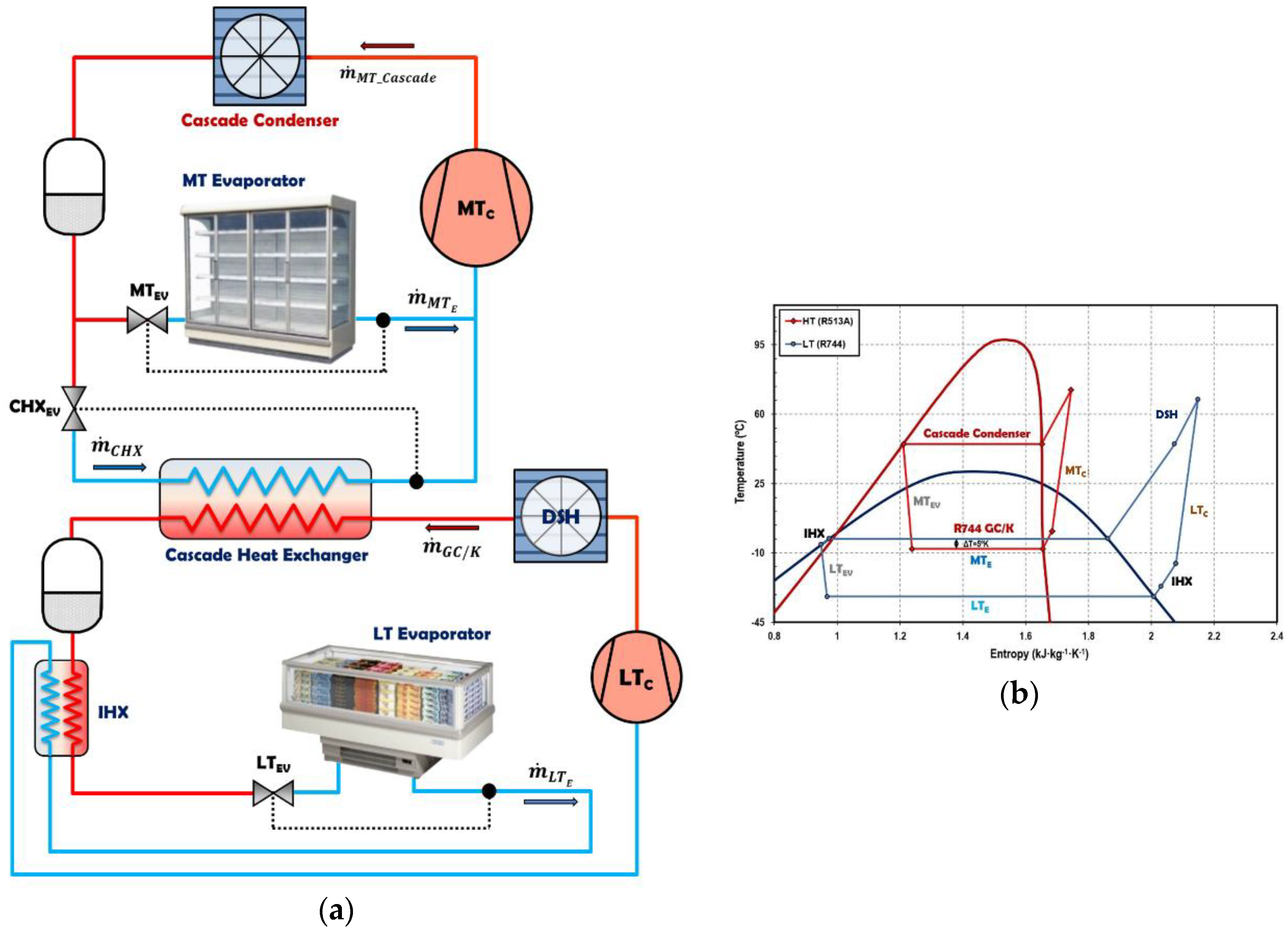
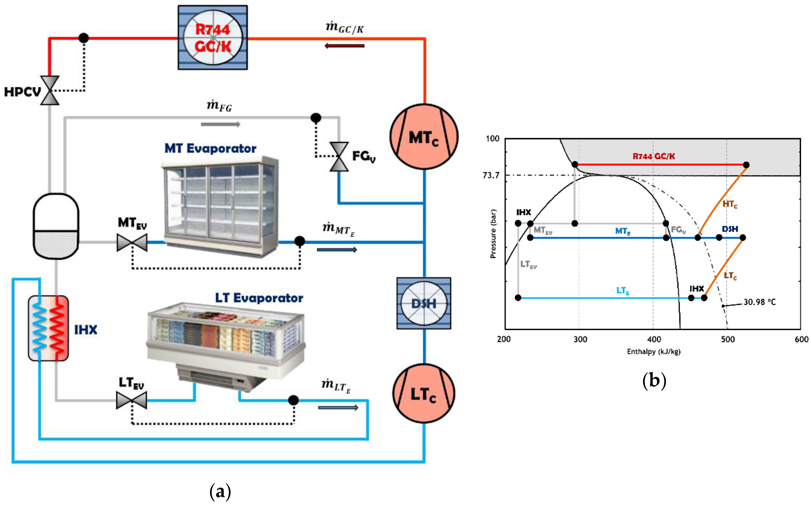
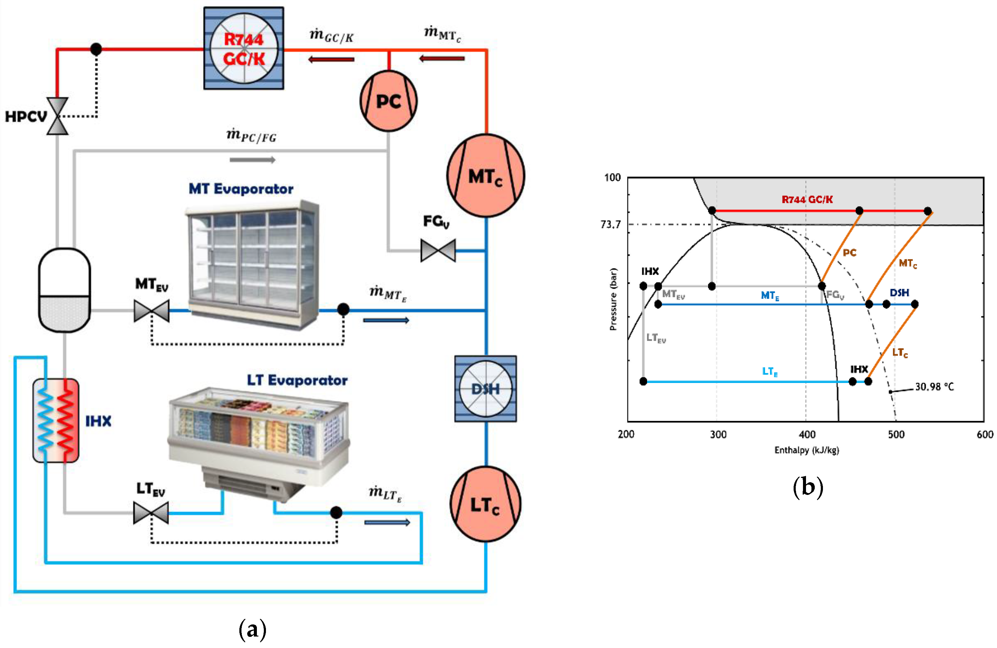
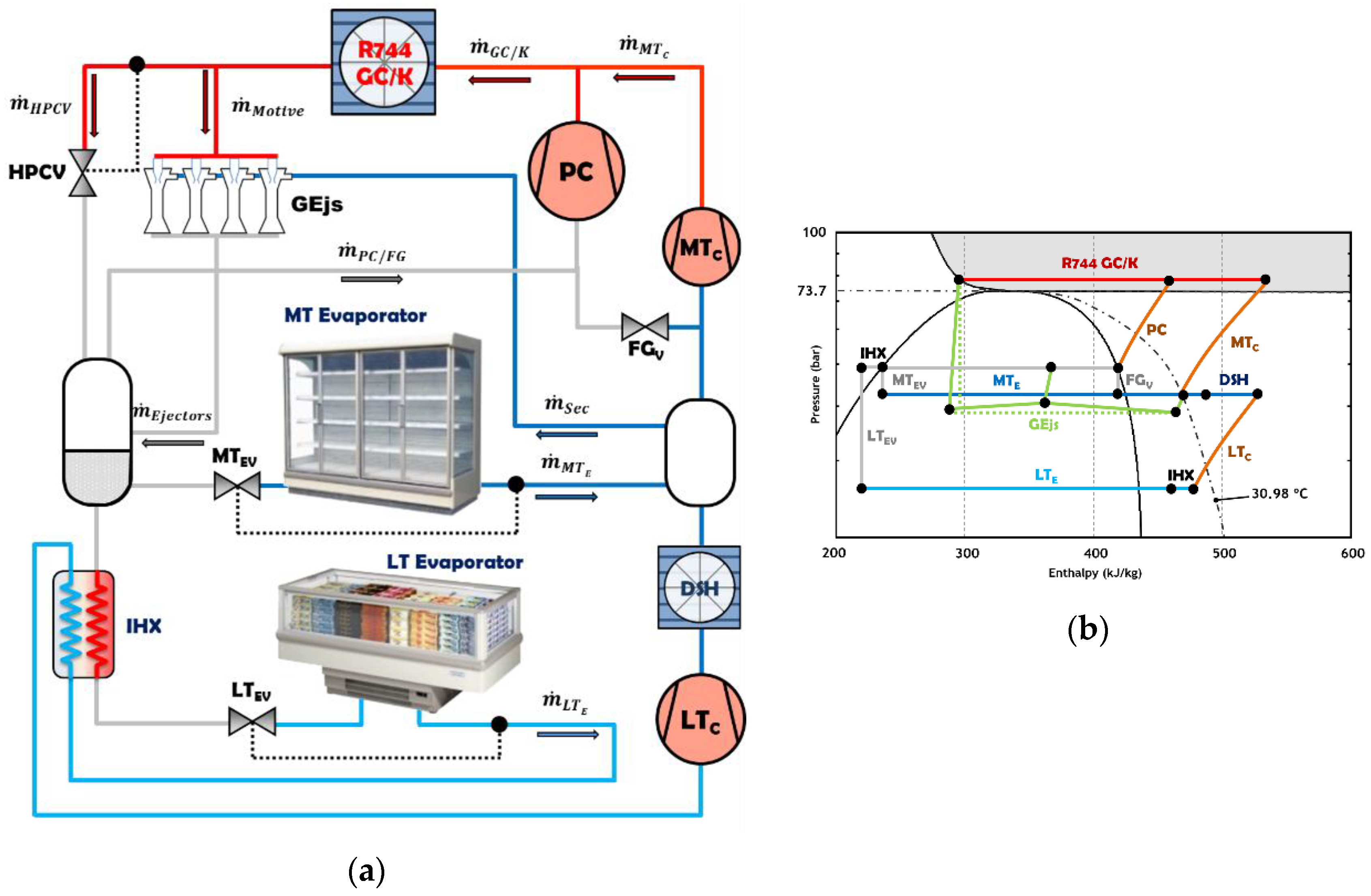
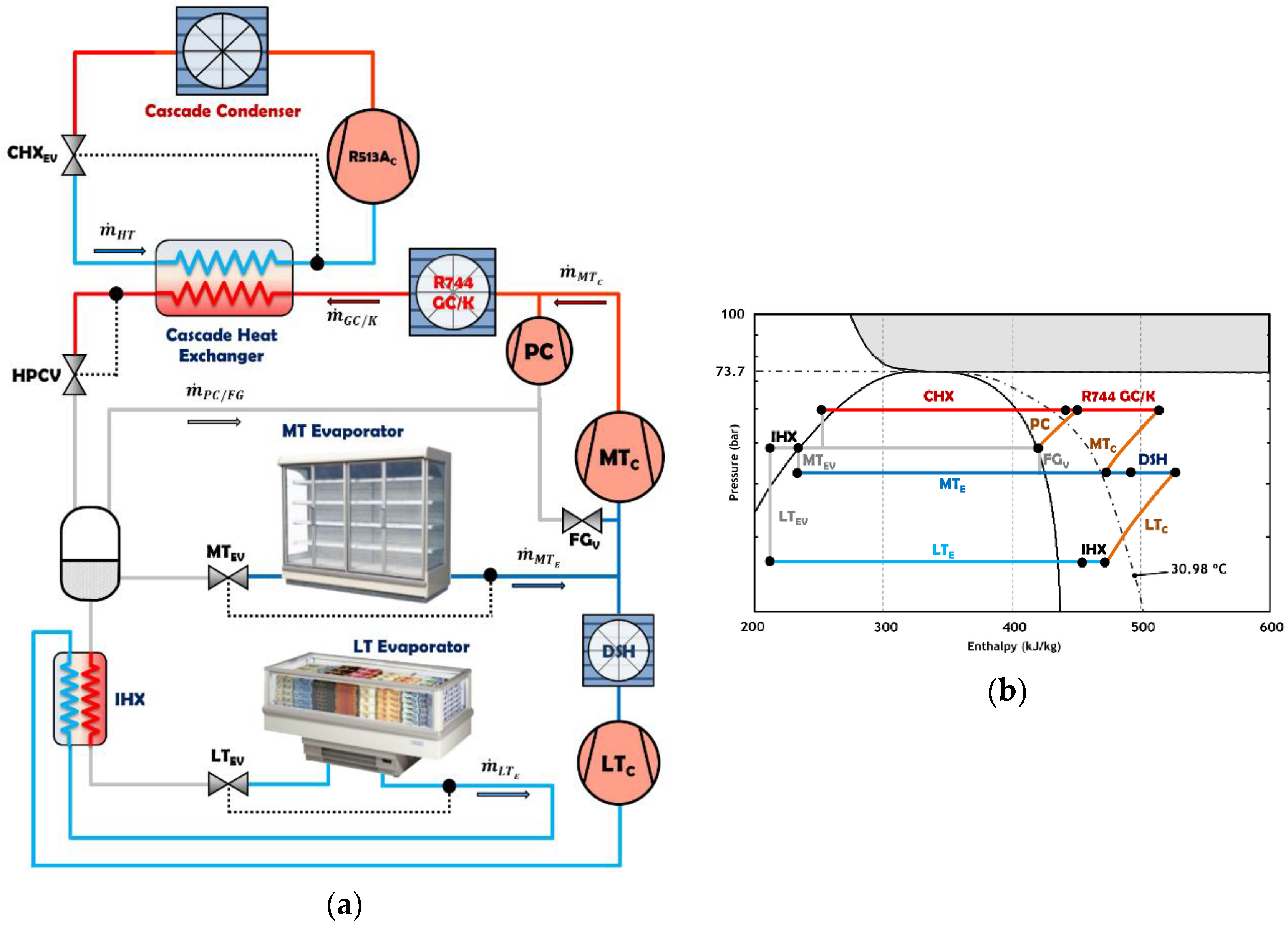
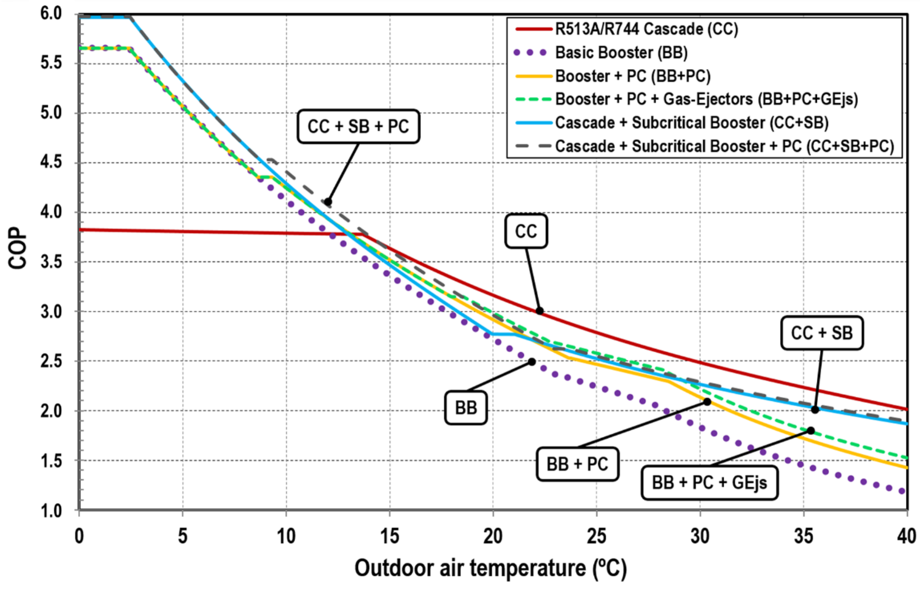
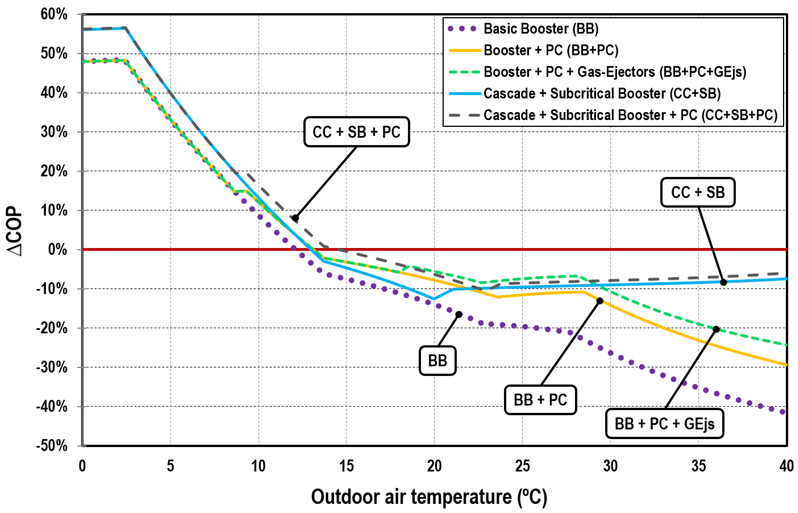
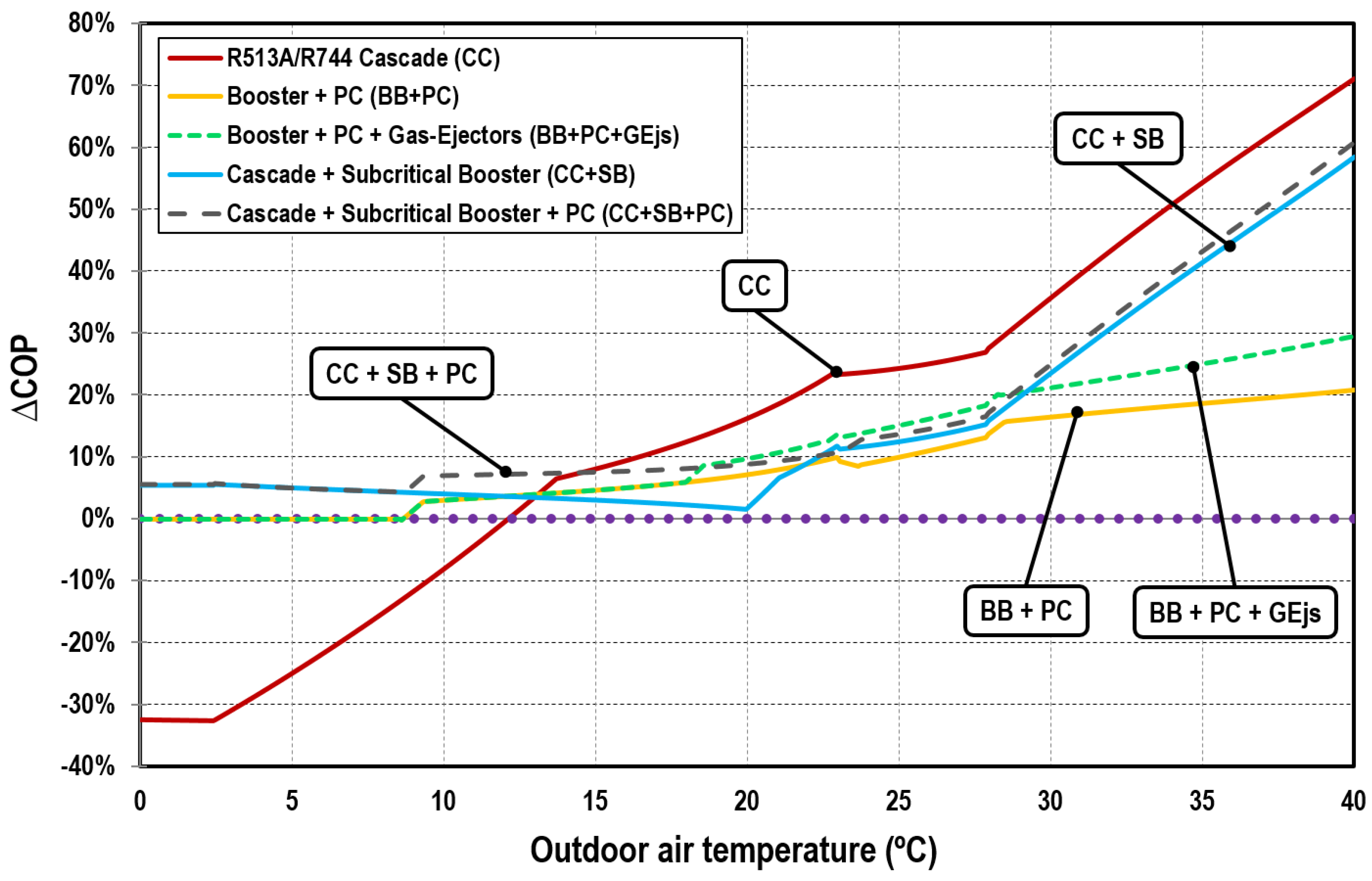
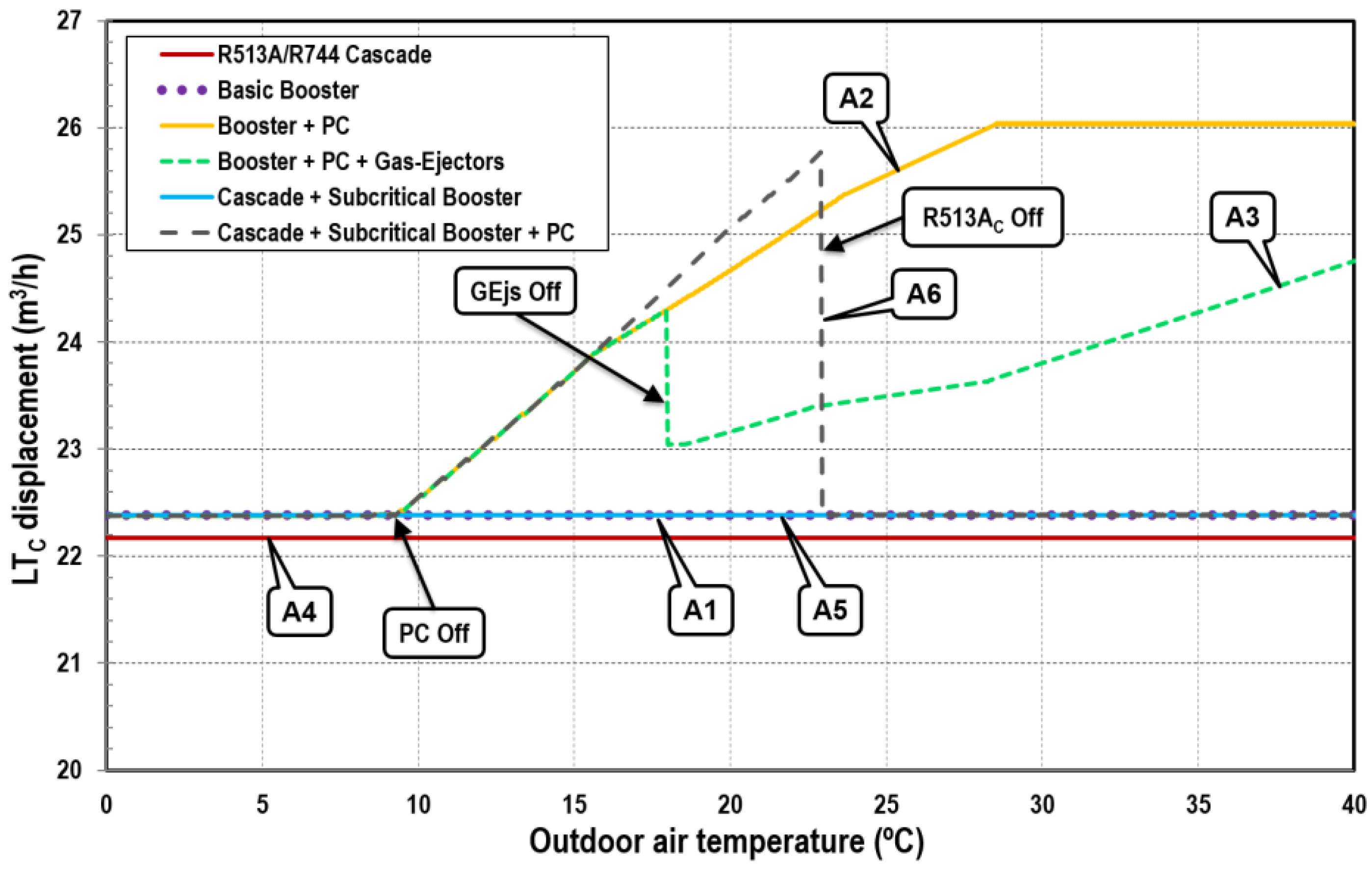
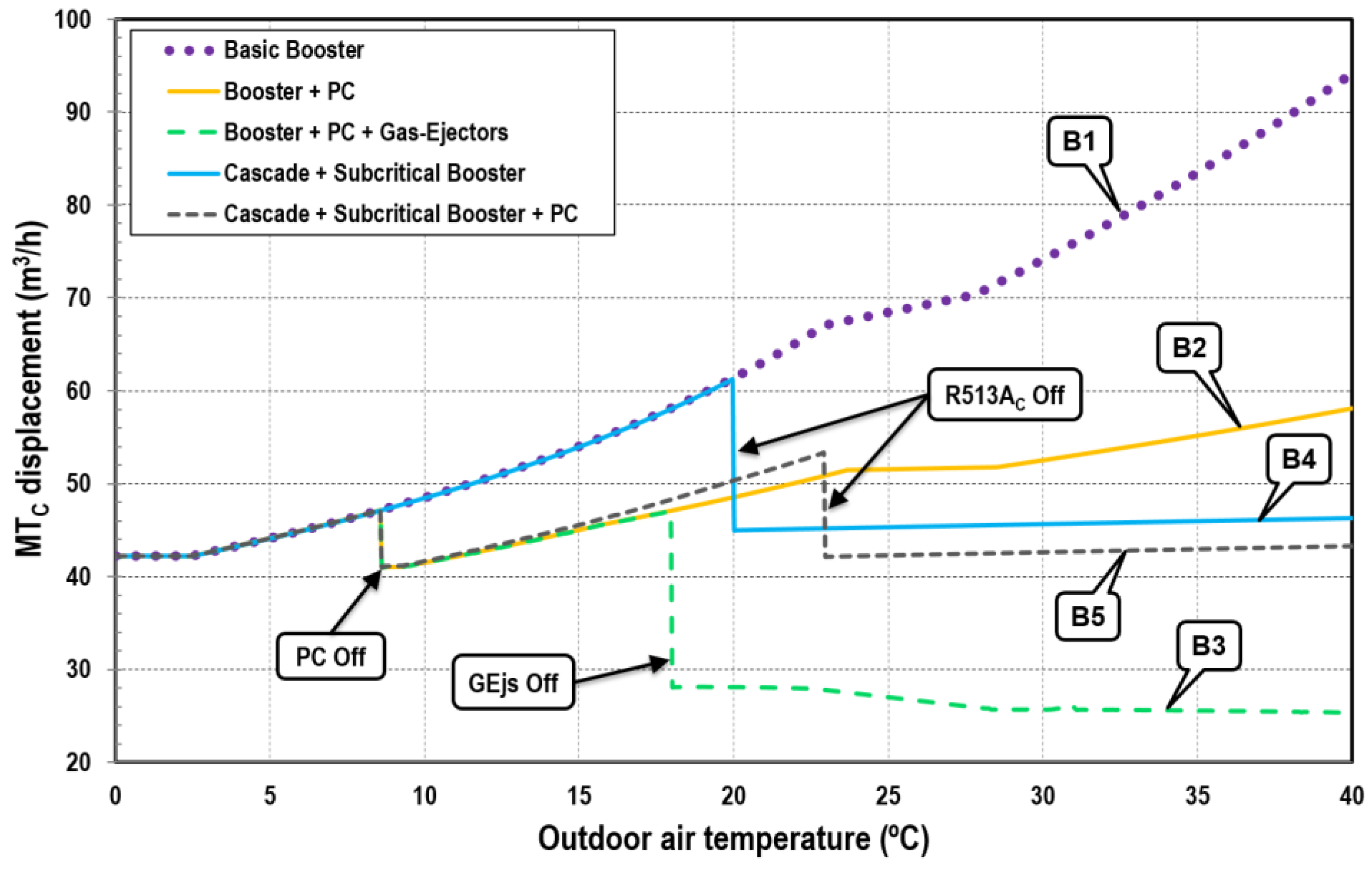
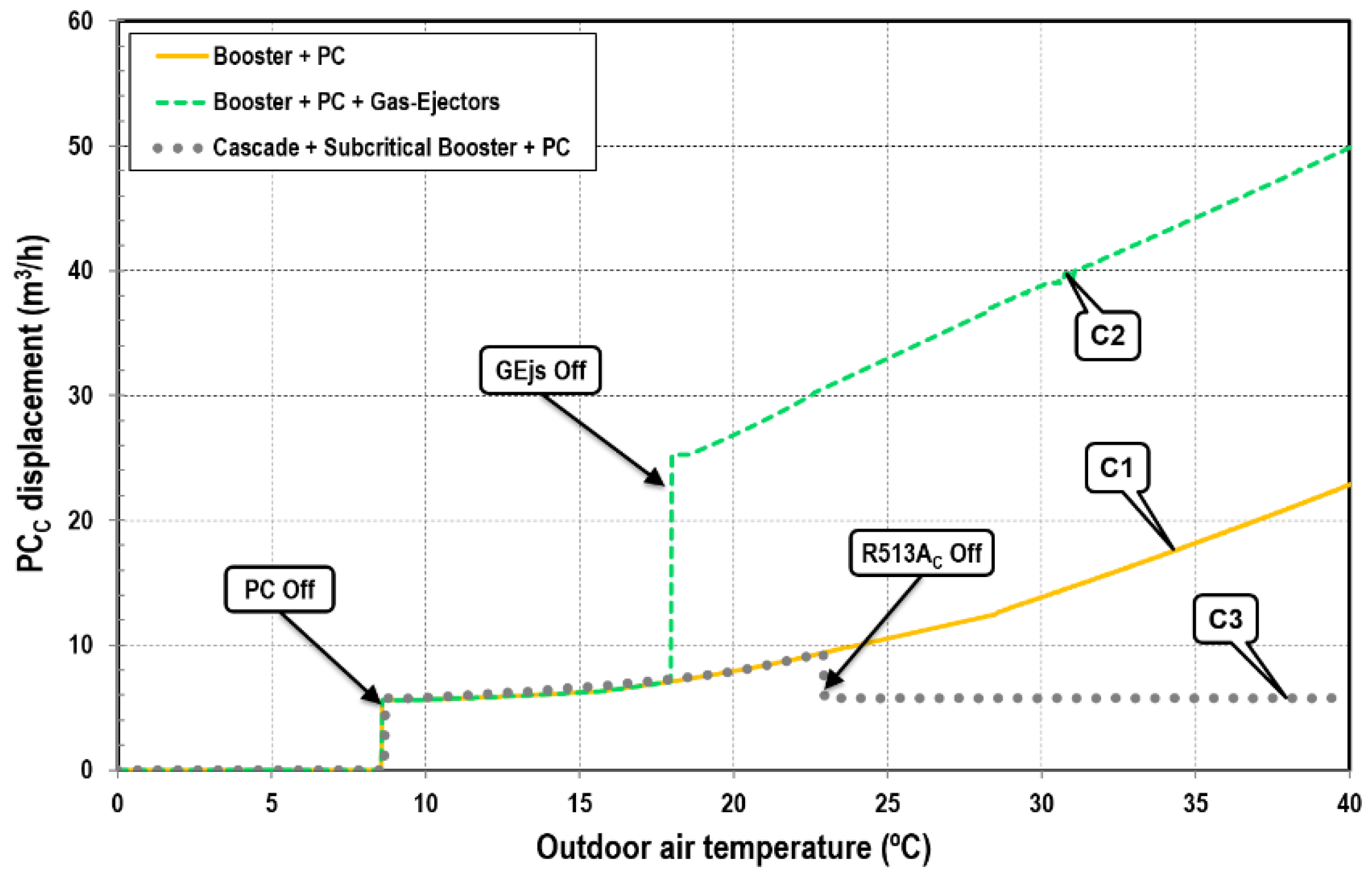
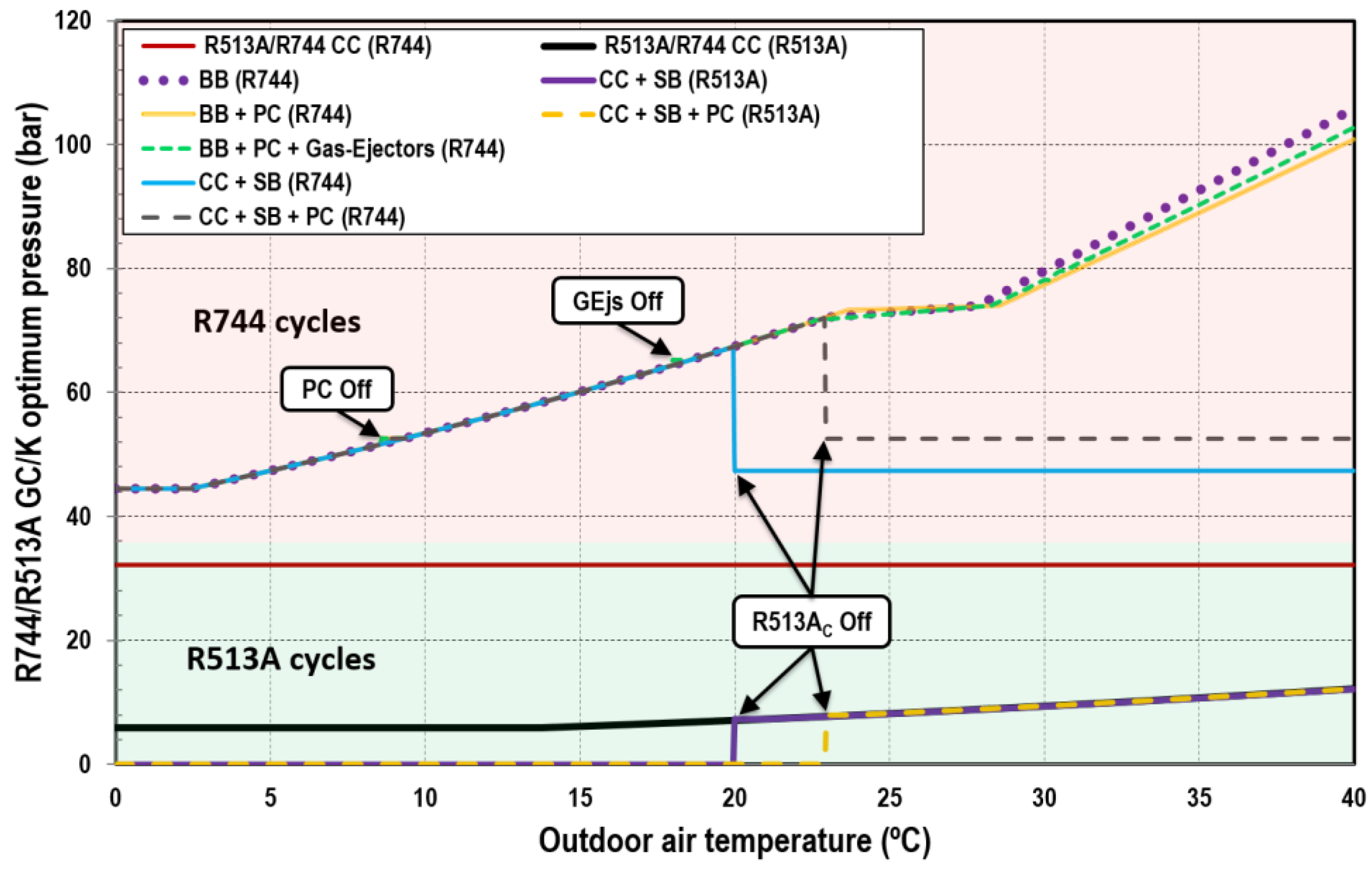
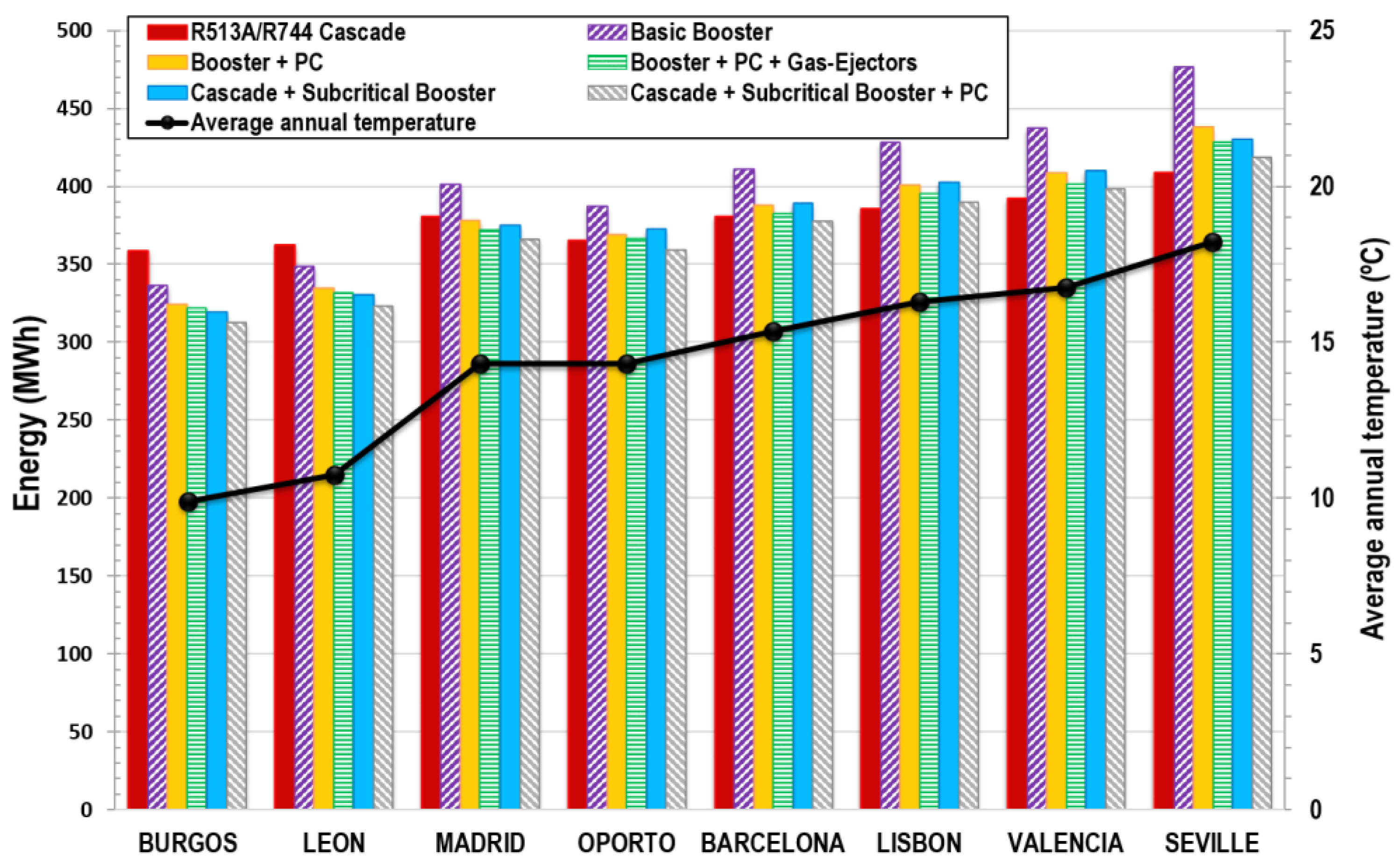
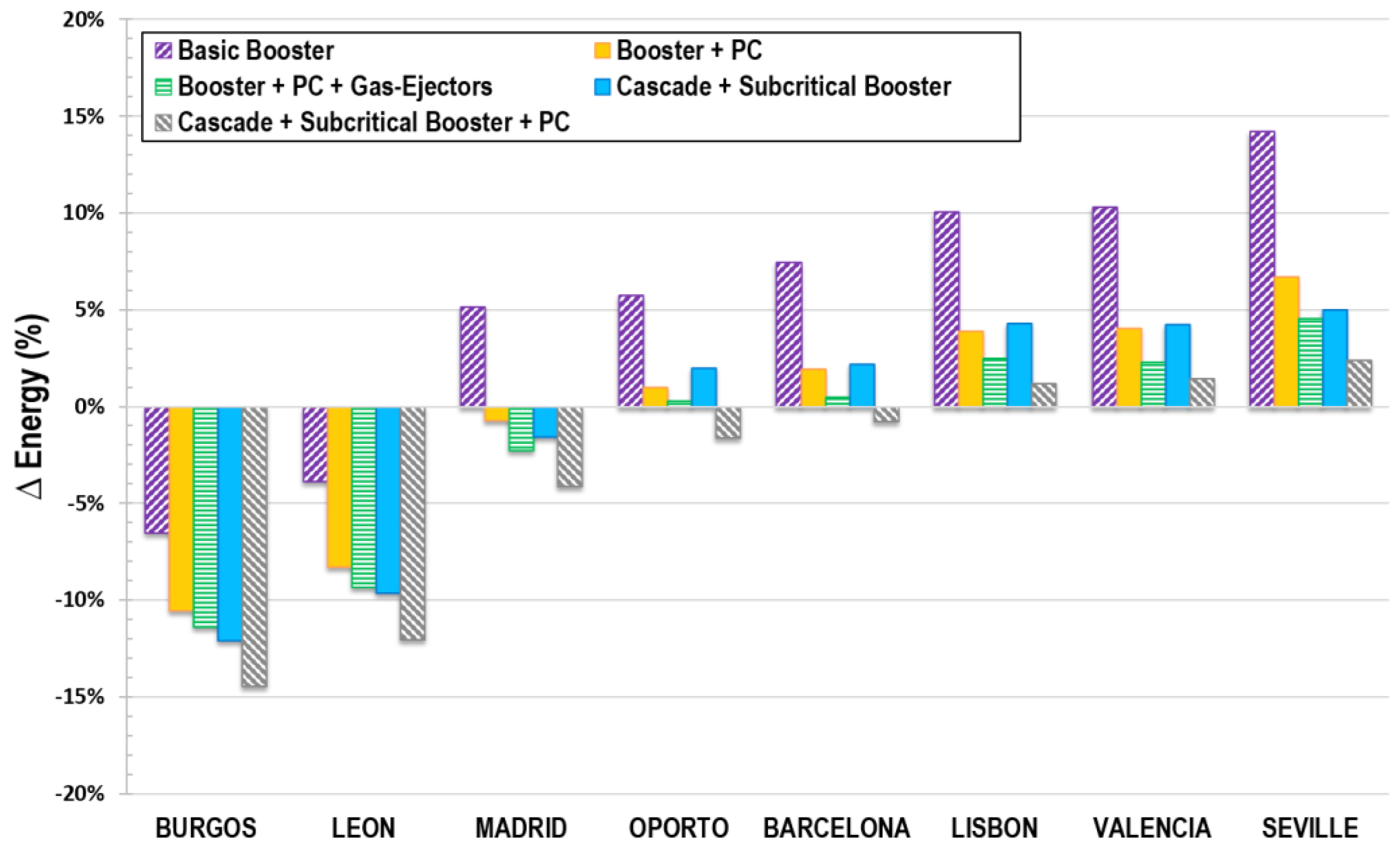
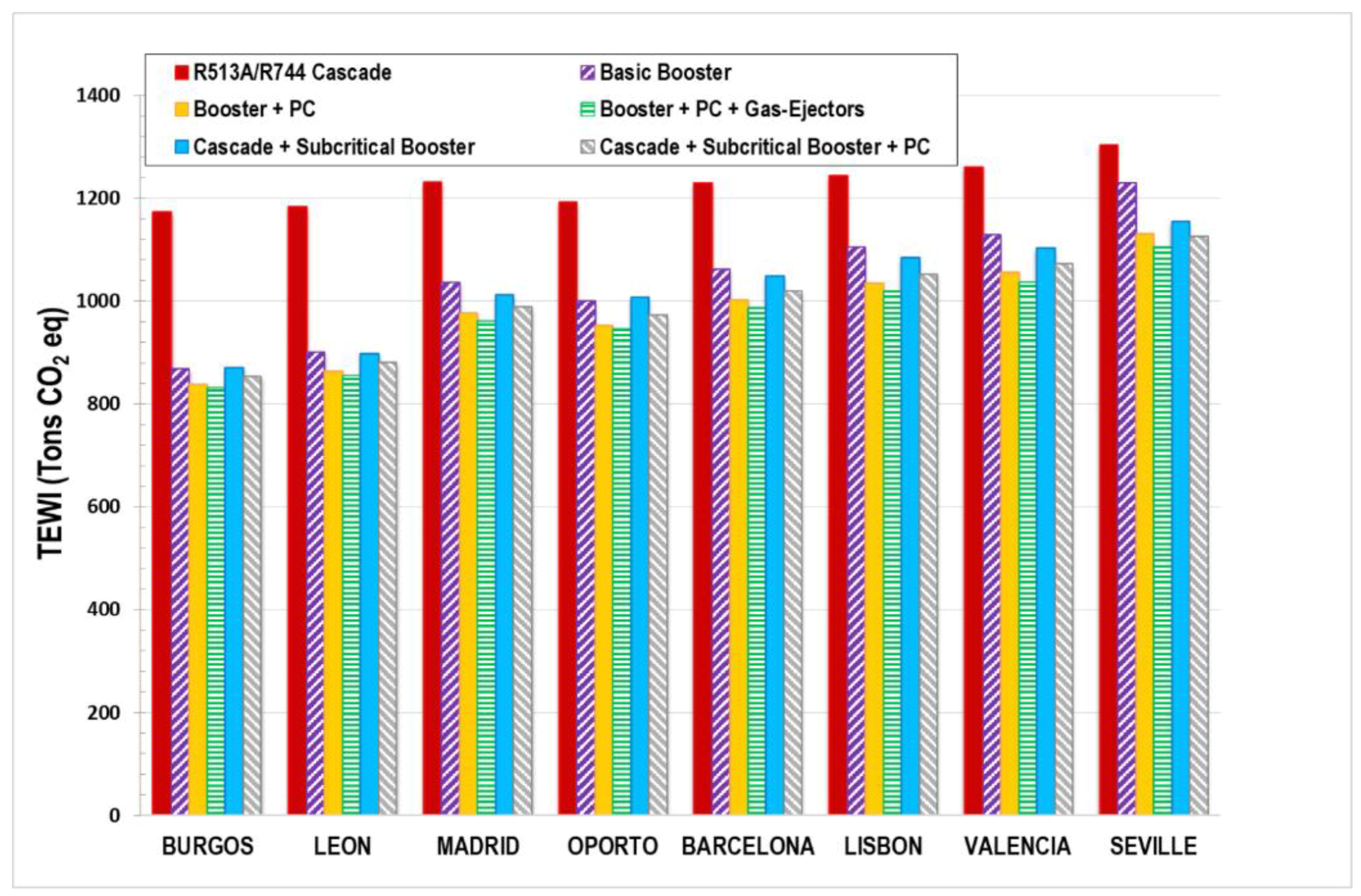
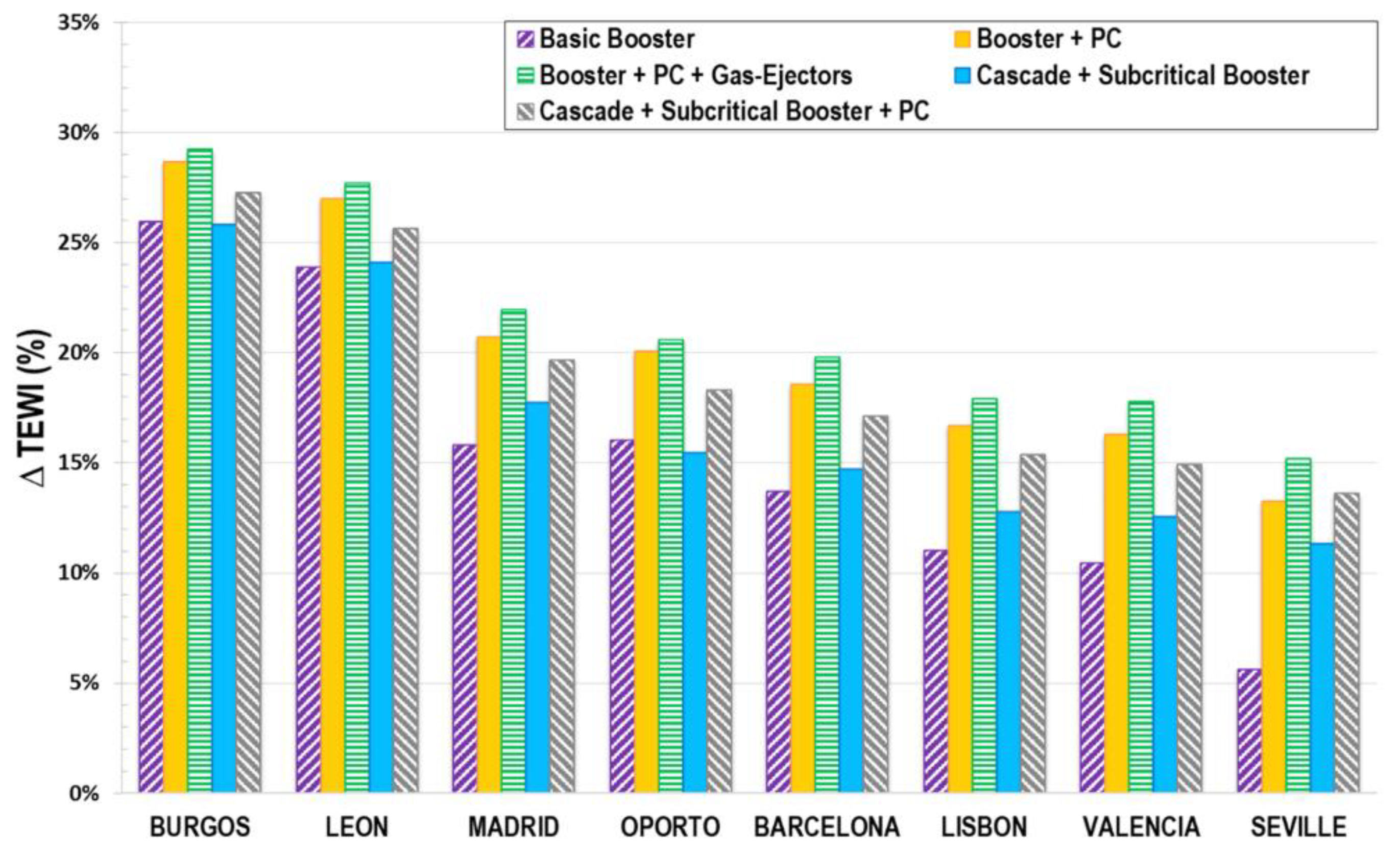
Table 1.
Summary data table.
| CC | CC + BB | CC + BB + PC | BB | BB + PC | BB + PC + GEjs | |
|---|---|---|---|---|---|---|
| Condensing Temp. (R513A) (°C) | Tenv + 5 | - | ||||
| Condensing Temp. (Subcritical R744) (°C) | −3 | 10 | 14.3 | Tenv + 5 | ||
| GCout Temp. (Transcritical R744) (°C) | - | Tenv + 2 | ||||
| Condenser Subcooling (R513A) (°C) | 0 | - | ||||
| Condenser Subcooling (Subcritical R744) (°C) | 0 | 2 | ||||
| DSHout Temp. (Subcritical R744) (°C) | Tenv + 5 | |||||
| LTE Temp. (°C) | −32 | |||||
| MTE Temp. (°C) | −8 | 5 | 9.3 | - | ||
| LTE, MTE and CHX superheating (K) | 5 | |||||
| Evaporatorsout useless superheating (K) | 5 | |||||
| LT Load (kW) | 41 | |||||
| MT Load (kW) | 140 | |||||
| Flash Tank Limit Pressures (bar) | - | 35 | 35–48.5 | 35 | 35–48.5 | 35–48.5 |
Table 2.
COP variation of each architecture compared with the R513A/R744 cascade (CC) and R744 basic booster (BB).
Table 2.
COP variation of each architecture compared with the R513A/R744 cascade (CC) and R744 basic booster (BB).
| Tair (°C) | BB | BB + PC | BB + PC + GEjs | CC + SB | CC + SB + PC | |||||
|---|---|---|---|---|---|---|---|---|---|---|
| ΔCOPCC (%) | ΔCOPBB (%) | ΔCOPCC (%) | ΔCOPBB (%) | ΔCOPCC (%) | ΔCOPBB (%) | ΔCOPCC (%) | ΔCOPBB (%) | ΔCOPCC (%) | ΔCOPBB (%) | |
| 0 | 47.95 | - | 47.95 | 0.00 | 47.95 | 0.00 | 56.03 | 5.46 | 56.03 | 5.46 |
| 5 | 33.16 | - | 33.16 | 0.00 | 33.16 | 0.00 | 39.88 | 5.05 | 39.88 | 5.05 |
| 10 | 8.99 | - | 12.29 | 3.03 | 12.29 | 3.03 | 13.44 | 4.08 | 16.62 | 7.00 |
| 15 | −7.42 | - | −3.12 | 4.64 | −3.12 | 4.64 | −4.57 | 3.08 | −0.43 | 7.55 |
| 20 | −13.89 | - | −7.75 | 7.13 | −5.54 | 9.69 | −12.51 | 1.60 | −6.30 | 8.82 |
| 25 | −19.53 | - | −11.54 | 9.93 | −7.45 | 15.02 | −9.50 | 12.46 | −8.55 | 13.65 |
| 30 | −26.19 | - | −14.07 | 16.42 | −10.61 | 21.11 | −8.95 | 23.36 | −7.90 | 24.78 |
| 35 | −35.12 | - | −23.04 | 18.63 | −18.92 | 24.97 | −8.36 | 41.24 | −7.18 | 43.07 |
| 40 | −41.48 | - | −29.32 | 20.79 | −24.27 | 29.40 | −7.41 | 58.23 | −5.98 | 60.66 |
Table 3.
Compressor displacements and their variation over all the range of environment temperatures analysed.
Table 3.
Compressor displacements and their variation over all the range of environment temperatures analysed.
| CYCLE | LTc (R744) | MTc (R744) | PC (R744) | HFCc (R513A) | ||||||||||||
|---|---|---|---|---|---|---|---|---|---|---|---|---|---|---|---|---|
| MODEL | dmin (m3/h) | dmax (m3/h) | dvar (%) | MODEL | dmin (m3/h) | dmax (m3/h) | dvar (%) | MODEL | dmin (m3/h) | dmax (m3/h) | dvar (%) | MODEL | dmin (m3/h) | dmax (m3/h) | dvar (%) | |
| BB | A1 | 22.4 | 22.4 | 0.0 | B1 | 42.2 | 94.2 | 38.1 | ||||||||
| BB + PC | A2 | 22.4 | 26.0 | 7.6 | B2 | 41.0 | 58.1 | 17.2 | C1 | 5.6 | 22.9 | 60.9 | ||||
| BB + PC + GEjs | A3 | 22.4 | 24.8 | 5.0 | B3 | 25.3 | 47.1 | 30.2 | C2 | 5.6 | 49.9 | 79.9 | ||||
| CC | A4 | 22.2 | 22.2 | 0.0 | D1 | 383.7 | 586.8 | 20.9 | ||||||||
| CC + SB | A5 | 22.4 | 22.4 | 0.0 | B4 | 42.2 | 61.2 | 18.4 | D2 | 247.7 | 364.9 | 19.1 | ||||
| CC + SB + PC | A6 | 22.4 | 25.8 | 7.0 | B5 | 41.0 | 53.3 | 13.0 | C3 | 5.7 | 9.4 | 24.0 | D3 | 212.7 | 302.0 | 17.4 |
Table 4.
Maximum optimum pressures.
| CYCLE | Max Popt (R744) (bar) | Max Popt (R513A) (bar) |
|---|---|---|
| BB | 105.8 | |
| BB + PC | 100.8 | |
| BB + PC + GEjs | 102.7 | |
| CC | 32.2 | 12.2 |
| CC + SB | 67.4 | 12.2 |
| CC + SB + PC | 72.1 | 12.2 |
© 2018 by the authors. Licensee MDPI, Basel, Switzerland. This article is an open access article distributed under the terms and conditions of the Creative Commons Attribution (CC BY) license (http://creativecommons.org/licenses/by/4.0/).
Share and Cite
MDPI and ACS Style
Catalán-Gil, J.; Sánchez, D.; Llopis, R.; Nebot-Andrés, L.; Cabello, R. Energy Evaluation of Multiple Stage Commercial Refrigeration Architectures Adapted to F-Gas Regulation. Energies 2018, 11, 1915. https://doi.org/10.3390/en11071915
AMA Style
Catalán-Gil J, Sánchez D, Llopis R, Nebot-Andrés L, Cabello R. Energy Evaluation of Multiple Stage Commercial Refrigeration Architectures Adapted to F-Gas Regulation. Energies. 2018; 11(7):1915. https://doi.org/10.3390/en11071915
Chicago/Turabian StyleCatalán-Gil, Jesús, Daniel Sánchez, Rodrigo Llopis, Laura Nebot-Andrés, and Ramón Cabello. 2018. "Energy Evaluation of Multiple Stage Commercial Refrigeration Architectures Adapted to F-Gas Regulation" Energies 11, no. 7: 1915. https://doi.org/10.3390/en11071915
Note that from the first issue of 2016, this journal uses article numbers instead of page numbers. See further details here.