Autonomous Control Strategy of DC Microgrid for Islanding Mode Using Power Line Communication


1
Department of Electrical Engineering, Pusan National University, Pusan 46241, Korea
2
Power Conversion and Control Research Center, HVDC Research Division, KERI, Changwon 51543, Korea
3
School of Electrical & Computer Engineering, Ulsan National Institute of Science and Technology (UNIST), Ulsan 44919, Korea
*
Authors to whom correspondence should be addressed.
Energies 2018, 11(4), 924; https://doi.org/10.3390/en11040924
Submission received: 28 February 2018
/
Revised: 8 April 2018
/
Accepted: 9 April 2018
/
Published: 13 April 2018
(This article belongs to the Section F: Electrical Engineering)
Abstract
:This paper proposes a DC-bus signaling (DBS) method for autonomous power management in a DC microgrid, used to improve its reliability. Centralized power management systems require communication between the power sources and loads. However, the DBS method operates based on the common DC-bus voltage and does not require communication. Based on the DC-bus voltage band, the DC-bus voltage can be used to inform the status of the DC-bus in various scenarios. The DC microgrid operates independently to maintain the system stably in the DC-bus voltage band. The DC microgrid can be divided into a grid-connected mode and an islanding mode. This paper proposes a control strategy based on power management of various independent components in islanding mode. In addition, the autonomous control method for switching the converter’s operation between grid-connected mode and islanding mode is proposed. A DC microgrid test bed consisting of a grid-connected AC/DC converter, a bidirectional DC/DC converter, a renewable energy simulator, DC home appliances and a DC-bus protector is used to test the proposed control strategy. The proposed autonomous control strategy is experimentally verified using the DC microgrid test bed.
1. Introduction
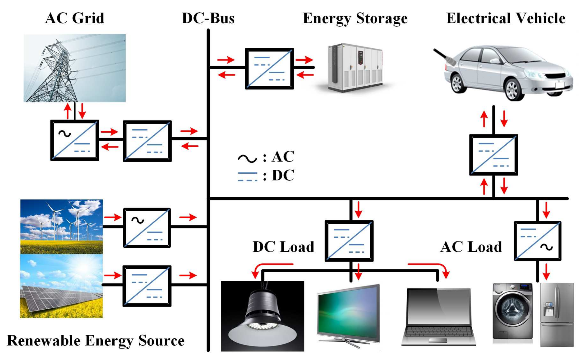
Recently, renewable energy sources such as photovoltaic (PV) cell and wind energy are being used to replace fossil fuels due to resource depletion and environmental issues such as pollution and climate change [1,2,3]. In addition, DC electronic loads such as LED lighting, electric vehicles and data centers have been widely used in industrial fields and commercial areas. In order to interface various renewable energy sources with a high demand for DC electronic loads, a DC microgrid has been developed in the past several years [4,5,6,7]. The DC microgrid can more easily integrate renewable energy sources than conventional AC distribution systems [8,9]. It can also interface energy storage systems (ESS) with the grid system and improve power transfer efficiency by reducing power conversion stages, as shown in Figure 1 [10,11].
A DC microgrid demands appropriate control methods, divided into centralized and distributed control, in order to supply sustainable electrical power to loads. The centralized control method controls each component in the DC microgrid, which requires communication and a central controller [12,13]. It uses a communication network to send operational commands that control power flows in the entire DC grid system. Since the central controller obtains operational information on all the system components, it directly determines and controls the power flow in the DC microgrid. However, the central control structure has a higher cost and a reliable communication network. In addition, the faults or disruptions in the communication system can lead to system operation failures and reliability problems, since the entire system operation depends on the communication network. To overcome this limitation, the distributed control method without a communication network has been proposed. This DC-bus signaling (DBS) method uses power lines instead of the communication network to communicate the DC microgrid’s status and information [14]. The DBS method is based on the DC-bus voltage level. By configuring the DC-bus voltage in bands, all components that make up the DC microgrid can operate independently using power flow information. It is cheaper and more reliable, because the DBS does not depend on a complex communication network.
The operation of a DC microgrid can be classified into grid-connected mode and islanding mode. In grid-connected mode, an AC/DC converter commonly controls the power flow between the AC grid and the DC microgrid. In islanding mode, the AC/DC converter cannot control the power flow, because the DC microgrid is not connected to the AC grid. Instead, the bidirectional power converter charging and discharging the ESS should autonomously take over control of the DC-bus voltage by detecting the AC grid fault. Several control methods using the DBS method have been previously applied to control DC microgrid, such as gain scheduling and droop control [15]. An improved DBS method is proposed in [16], the switching frequency modulation of a grid-connected DC/DC converter was utilized as the operating information for the power line communication. However, this method requires additional component such as spectrum analyzer. The DBS method has also been applied to PV and ESS controls [17,18]. In grid-connected mode, the DBS method is applied to the voltage droop control between the solid-state transformer (SST) and the ESS [19]. However, previous research only focused on the grid-connected mode, without considering the islanding mode operation. The DC microgrid requires emergency operations when the system becomes islanded; however, the control method and operating strategy of islanding mode have not been thoroughly studied yet. In the case of islanding mode, each DC microgrid component should be able to identify fault situations to operate independently. In addition, according to the AC grid status, the operational mode of the DC microgrid should autonomously change from grid-connected mode to islanding mode and vice versa. This autonomous operation has also not been fully studied using the DBS method. The DC-bus voltage of the DC microgrid is regulated by the bidirectional AC/DC converter in grid-connected mode. On the contrary, when AC grid faults occur, the ESS controls the DC-bus voltage using electric power stored in its battery during islanding mode. If the AC grid restores normal function in islanding mode, control of the DC-bus voltage will be conflicted by two voltage sources, since the AC/DC converter connected to the AC grid starts to regulate the DC-bus voltage in grid-connected mode. In the conventional DBS method using the DC-bus voltage level, the ESS converter will not be able to recognize this situation. It is a fatal weakness for implementing autonomous DC microgrid systems using only the conventional DBS method.
In this paper, in order to overcome this weakness in the conventional DBS method, an enhanced DBS method for islanding mode is proposed to achieve power management with the bidirectional converters to improve the stability of the DC microgrid. In addition, the recovery control strategy for switching the operation of the converter between grid-connected mode and islanding mode using power line communication is proposed. This paper proposes a prototype test bed of a 380 V DC microgrid for home and small building power distribution systems. It is implemented with a bidirectional AC/DC converter, a renewable energy simulator, a bidirectional DC/DC converter for the ESS, DC loads including DC home appliances, and a DC protector. Because it applies to DC microgrids for home and small building power distribution systems, only one ESS is considered. The proposed power management algorithm in islanding mode and recovery control strategy using power line communication are implemented to verify the functionality and performance of the DBS method in the 380 V DC microgrid test bed system.
2. Configuration of DC Microgrid
The prototype test bed of the 380 V DC microgrid consists of a bidirectional AC/DC converter, a renewable energy simulator, a bidirectional DC/DC converter for the ESS, DC loads, and DC home appliances. This paper focuses on the autonomous power management algorithm of three isolated power converters and a DC-bus protector.
2.1. DC Microgrid Structure
The bidirectional AC/DC converter is composed of a non-isolated bidirectional AC/DC converter and an isolated bidirectional DC/DC converter for regulating DC-bus voltage. Galvanic isolation capability is required for the safety of end users who live in those places, because DC microgrids can be used as power distribution systems for houses and small buildings. The prototype 5 kW AC/DC converter is designed according to a single-phase boost converter topology using a unipolar sinusoidal pulse width modulation (SPWM) method [20]. In addition, among various bidirectional DC/DC converters, a dual active bridge (DAB) converter is used as the isolated 5kW DC/DC converter for galvanic isolation with high-efficiency bidirectional power conversion, because it has an inherent soft-switching operation [21]. The output voltage is regulated to 380 V by a phase shift modulation (PSM) method in a seamless control manner for bidirectional power flows [22].
A battery-based ESS requires a bidirectional DC/DC converter to interface with the DC microgrid. The applied 3 kW bidirectional DC/DC converter prototype was also developed using the DAB converter topology with a battery voltage range of 150 V to 200 V. The output voltage is regulated in a seamless control manner for battery charging and discharging operations. Therefore, it is useful to the application of power delivery for the battery and can allow for flexible power interfacing between the DC microgrid and the ESS [23,24,25,26]. In addition, the DAB converter can operate under high efficiency and has galvanic isolation.
The renewable energy simulator is used to emulate the power generation of renewable energy sources such as photovoltaic (PV), fuel cell (FC), wind turbine, etc. It acts as a distributed power generator connected to the DC microgrid. Since the ESS converter exists to stably maintain the DC microgrid, the renewable energy simulator is only considered as the model that produces the maximum power without involving DC-bus voltage control. In addition, the DC-bus voltage is regulated by the AC/DC converter, and the simulator should operate as a current source type converter connected to the DC-bus. Since the output power of the renewable energy source depends on various environmental conditions, it is difficult to make an exact design of the renewable energy simulator. Therefore, the renewable energy simulator is simply designed to operate with three current steps of 1 A, 4 A, and 7.5 A to test dynamic responses of the DC microgrid. The output current changes over 15 s and holds the DC voltage level over 20 s. The proposed renewable energy simulator consists of a bridgeless power factor correction (PFC) boost rectifier and LLC resonant converter. The bridgeless PFC boost rectifier has a regulated voltage of 380V and is used as the input voltage of the LLC resonant converter. The LLC resonant converter topology is used for the renewable energy simulator with the bridgeless PFC rectifier because it has high power conversion efficiency, high power density and its zero voltage switching (ZVS) capability over the entire load range [27,28,29].
The DC-bus protector consists of an insulated gate bipolar transistor (IGBT) and a 3kW resistor to suppress DC bus voltage in case of an abnormal increase in DC bus voltage. When the DC-bus voltage increases due to a problem on the DC microgrid, it is composed of 3 kW, which is equal to the rated power of the renewable energy source, in order to consume the power generated by the renewable energy source.
2.2. Operating Mode
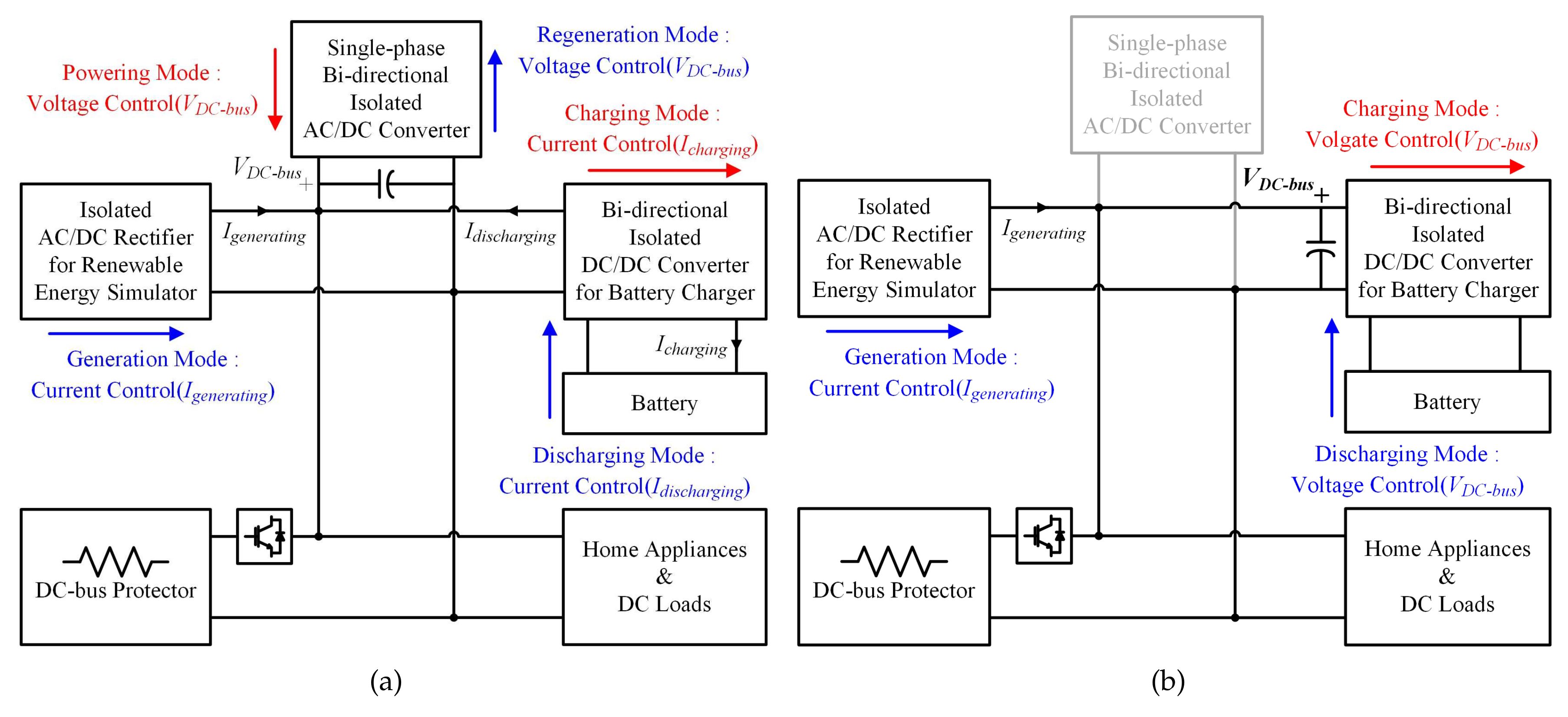
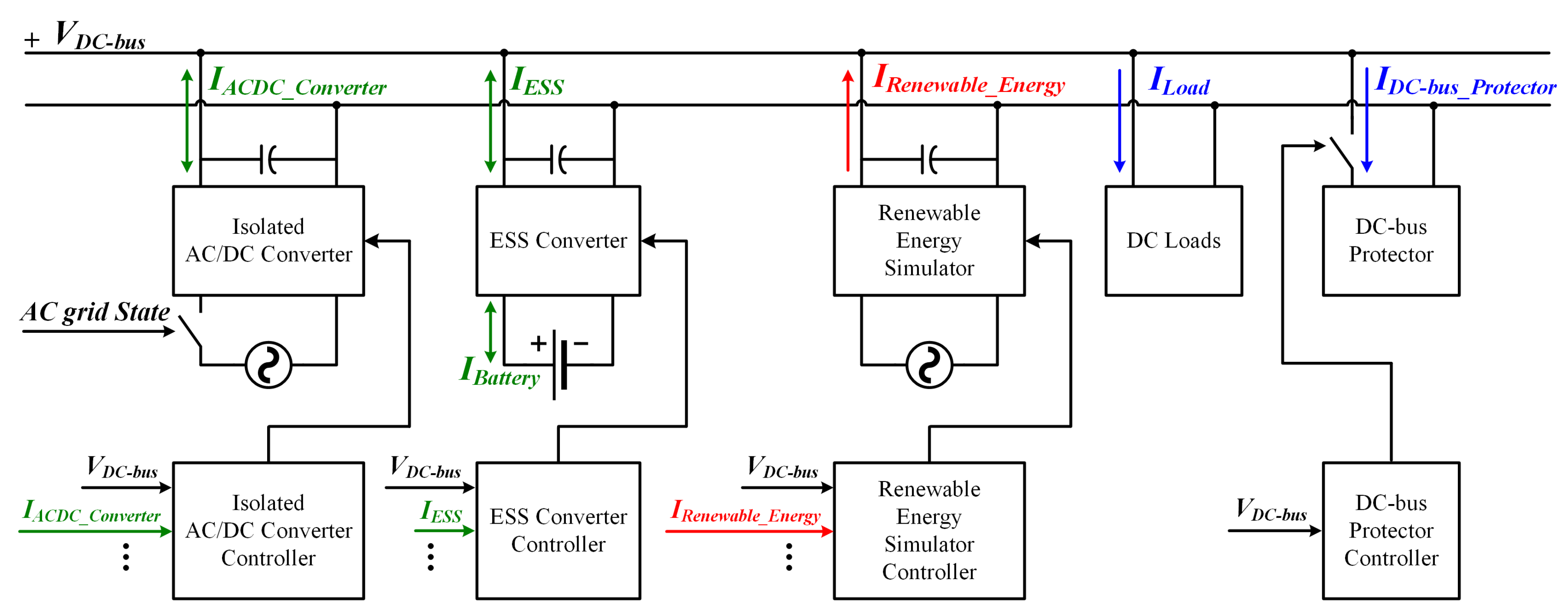
The operating mode of the DC microgrid is classified as grid-connected mode or islanding mode. In grid-connected mode, the isolated bidirectional AC/DC converter regulates the DC-bus voltage used for power interaction between the DC microgrid and the AC grid, as shown in Figure 2a. The renewable energy simulator constantly generates current that emulates distributed power generation. It charges the battery through the bidirectional DC/DC converter and supplies electric energy to the DC loads. Figure 2b shows islanding mode, in which the power flow of the DC microgrid can no longer be controlled through the AC/DC converter. Instead, the DC-bus voltage should be regulated by the bidirectional converter of the ESS. Regardless of the DC microgrid’s operation mode, the renewable energy simulator consistently supplies electric power to the DC microgrid. In order to increase the reliability of the DC microgrid under various operating conditions, a communication method between the AC/DC converter and the ESS converter should be required to properly switch between operating modes.
3. Proposed Control Strategy for Autonomous Operation of DC Microgrid
For communication between the converters connected to the DC microgrid, a DC-bus signaling (DBS) method can be used as the power line communication. In general, the DBS method uses DC-bus voltage level as information about the DC microgrid’s operating status. In order to reliably recognize the status of the DC microgrid, DC-bus voltage bands are proposed to classify operating conditions of the DC microgrid, and they are composed of the voltage levels by 10 V difference from the DC-bus voltage reference (380 V) as shown in Figure 3.
These have two boundaries, the controlled voltage of the energy storage system () and the voltage of the protection boundary point (). The voltage band from (370 V) to (390 V) is a normal regulation region for DC-bus voltage control. The voltage levels of (360 V) and (400 V) are boundary voltage levels used to protect the system from unacceptable fluctuations of the DC-bus voltage. The DC microgrid operations can be divided into grid-connected mode, controlled by the isolated bidirectional AC/DC converter, and islanding mode in abnormal operating situations. Various control methods, such as gain scheduling and voltage droop control, have been proposed for grid-connected mode. The specific control method for grid-connected mode is not with in the scope of this paper. Instead, a the power management algorithm in islanding mode is proposed. In addition, this paper also suggests autonomous control strategies between grid-connected mode and islanding mode to maintain reliability, depending on the AC grid conditions.
3.1. Control Strategy for Entering lslanding Mode
When the AC/DC converter can no longer control the power flow of the DC microgrid, the DC-bus voltage will not be regulated. In order to operate in islanding mode, a criterion is needed to distinguish between grid-connected mode and islanding mode. This paper proposes a criterion that recognizes islanding mode when the DC-bus voltage decreases below for the first time. However, if the AC grid malfunctions when the DC load is less than the power generation, the DC-bus voltage will not drop to , but conversely will rise to . Then, the DC-bus protector operates to drop the DC-bus voltage to to protect the DC microgrid, so this is not a problem. Conversely, if the DC load is larger than the power generation, the DC-bus voltage decreases below for the first time, and the ESS converter will recognize that the DC microgrid entered islanding mode and regulate the DC-bus voltage by changing its control method from current control to voltage control.
In the DC microgrid structure shown in Figure 2b, the obstacles to the power management of the microgrid in islanding mode are as follows:
- The battery of ESS is fully charged or discharged.
- The renewable energy source operates malfunction.
- The DC load is overload condition.
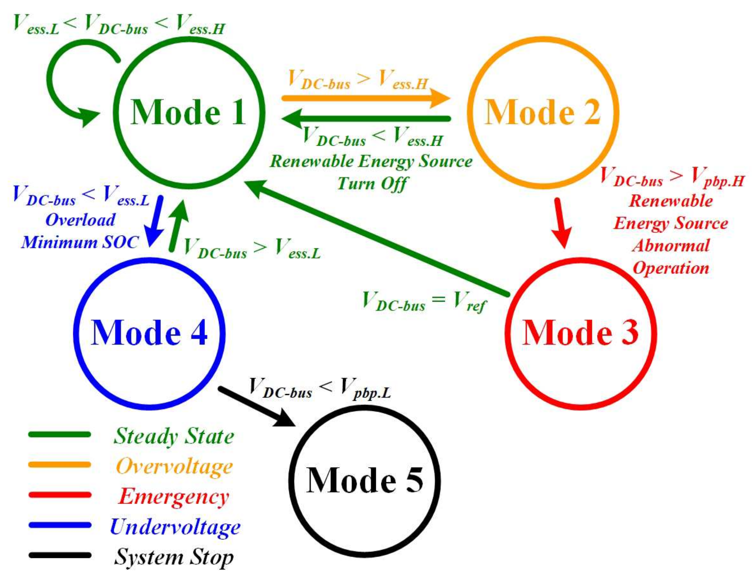
In order to maintain DC microgrid as stable as possible under the following conditions, a power management algorithm is proposed to protect DC microgrids in islanding mode operation from abnormal AC grid or malfunction of the AC/DC converter. Table 1 shows the classified operation states of the DC microgrid for all power components connected to it in islanding mode, based on the proposed power management algorithm for protecting the DC microgrid, as illustrated in Figure 4. All the components individually operate in the DC microgrid to achieve effectiveness and safety during islanding operation according to the DC-bus voltage band.
Mode 1: The ESS converter takes charge of the DC-bus voltage control in the voltage band of to , as illustrated in Figure 3. The power flow of the ESS converter in islanding mode follows Equation (1).
determines the charging or discharging behavior of the ESS converter. The ESS converter charges the battery while the power consumption of the load is less than the power generated from the renewable energy source. Conversely, if the power consumption of the load is higher than the power generated from the renewable energy source, the ESS converter will discharge the battery to provide electric power to the DC microgrid. These conditions are defined in mode 1, shown in Table 1, which is the normal operation of islanding mode when the ESS converter regulates the DC-bus voltage between the voltage band of to .
Mode 2: Since the DC-bus voltage regulation achieved by the ESS converter in islanding mode depends on the charging and discharging operations of the battery, fully charged or fully discharged battery condition should be considered. If the battery is fully charged, the ESS converter will not be able to charge the battery any more. At that time, the battery-charging current will be limited by the ESS converter, and there is no way to prevent the DC-bus voltage increment using only the ESS converter. When the DC-bus voltage is up to the voltage level of , which is defined as mode 2, the power generation from the renewable energy source should be stopped to prevent the increment of the DC-bus voltage level. When the power generation from the renewable energy source stops, the DC-bus voltage will decrease back to due to the power consumption of the DC load. The DC-bus voltage is regulated by the discharging operation of the ESS converter with the fully charged battery.
Mode 3: When the DC-bus voltage level goes up to and the renewable energy source continuously generates electric power, which is an abnormal condition, the DC-bus voltage will be higher than , which is defined as mode 3. At that time, the DC-bus protector will turn on to decrease the DC-bus voltage below to protect the DC microgrid as well as itself.
Mode 4: When the battery is under its minimum state of charge (SOC) or if the power consumption of the DC load is greater than the total power generated by the renewable energy source and the ESS, the DC-bus voltage will decrease without any regulation. When the DC-bus voltage decreases to , which is defined as mode 4, the ESS converter will operate in standby mode to gradually limit the battery discharging current, and will continuously discharge the battery as much as possible. In addition, in this mode, it will be necessary to wait for the generation of renewable energy sources to increase the stored energy in the ESS or to inform the customer in order to reduce the load.
Mode 5: If the DC-bus voltage is decreased to below due to continuous overload or a power shortage in the battery, the entire DC microgrid system should be stopped to protect itself and other power components connected to it. This is defined as mode 5.
The proposed power management algorithm in Figure 4 can cope with a variety of situations that can occur in islanding mode of the DC microgrid, assuming that there is no fault in each component that is not related to power management.
3.2. Control Strategy for Recovering Grid-Connected Mode
In AC grid failure, by sensing serious fluctuations of the DC-bus voltage (), the ESS converter can start regulating it in islanding mode. Conversely, if the AC grid state recovers, the operation of the DC microgrid should be returned to grid-connected mode. When the AC/DC converter restarts by recovering the AC grid, it should regulate the DC-bus voltage as a voltage source. At that time, the DC-bus voltage control will be hit by two voltage sources, the AC/DC converter and the ESS converter. Since the ESS converter already controls the DC-bus voltage during islanding mode, the conflict of its control is expected just after recovering the grid-connected mode. It is difficult for the ESS converter to recognize the AC grid recovery using the DBS based on the DC-bus voltage level. This is a major challenge in designing an autonomous DC microgrid system.
In order to overcome this challenge in the autonomous DC microgrid system using the DBS method, a recovery control strategy is proposed to change between islanding mode and grid-connected mode. The DC-bus voltage is regulated by the ESS converter during islanding mode. When the AC/DC converter is recovered, in order to avoid a control collision of the DC-bus voltage between the AC/DC converter and the ESS converter as the voltage sources, the AC/DC converter should first be connected to the DC-bus as a current source. After connecting of the AC/DC converter to the DC-bus, it should send the ESS converter information on its recovery and connection to request the authority of the DC-bus voltage control. This is a key point of the proposed recovery control strategy, which is a simple communication method between the AC/DC converter and the ESS converter using the power line of the DC microgrid to recover the grid-connected mode.
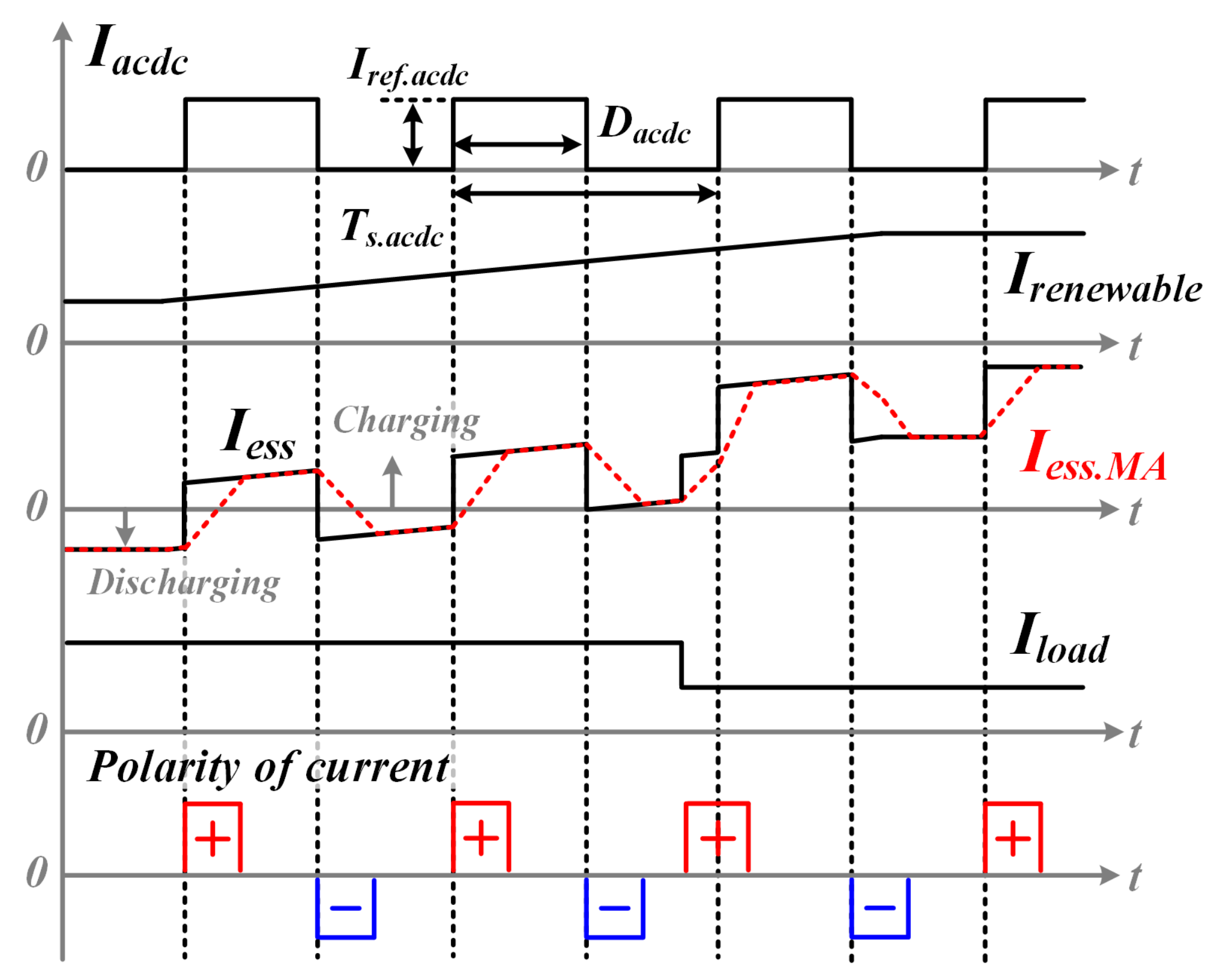
The proposed recovery control strategy makes the AC/DC converter generate a specific current pattern as shown in Figure 5. Just after the AC/DC converter is recovered, it will be connected to the DC-bus as a current source. Therefore, the AC/DC converter can generate the current pattern to the DC-bus. The specific current pattern is configured as a square pulse train that has an amplitude of , a pulse width of and a constant cycle time of . That kind of specific current pattern can be changed flexibly according to the conditions of the DC microgrid. In this paper, the square pulse train as the current pattern is implemented to 2.5 A , 0.5 duty, and a 2.5 s period.
When the AC/DC converter supplies current to the DC microgrid, in order to regulate the DC-bus voltage, the ESS converter will charge or discharge the battery. Therefore, when the AC/DC converter supplies the specific patterned current to the DC-bus, the ESS converter has the same shape, as shown in Figure 5. However, because the special pattern of the ESS converter is affected by the current generated from the renewable energy source or the change of the DC load, as shown in Figure 5, it is difficult to have stable power line communication by using the current pulse train. This paper proposes a method that uses a moving average to resolve this vulnerability. The moving average does not mean the average of all the data to be obtained, but the average of parts of all the data sequentially. Therefore, the special current pattern of the square pulse train is recognized in the ESS converter, and the moving average value () gradually increases and decreases as shown in Figure 5. The moving average value does not change instantaneously, but gradually, so when the current of the ESS converter changes rapidly, there is a difference between the moving average value and the present current state. Figure 5 describes this difference, used to construct the control algorithm of the proposed recovery control strategy.
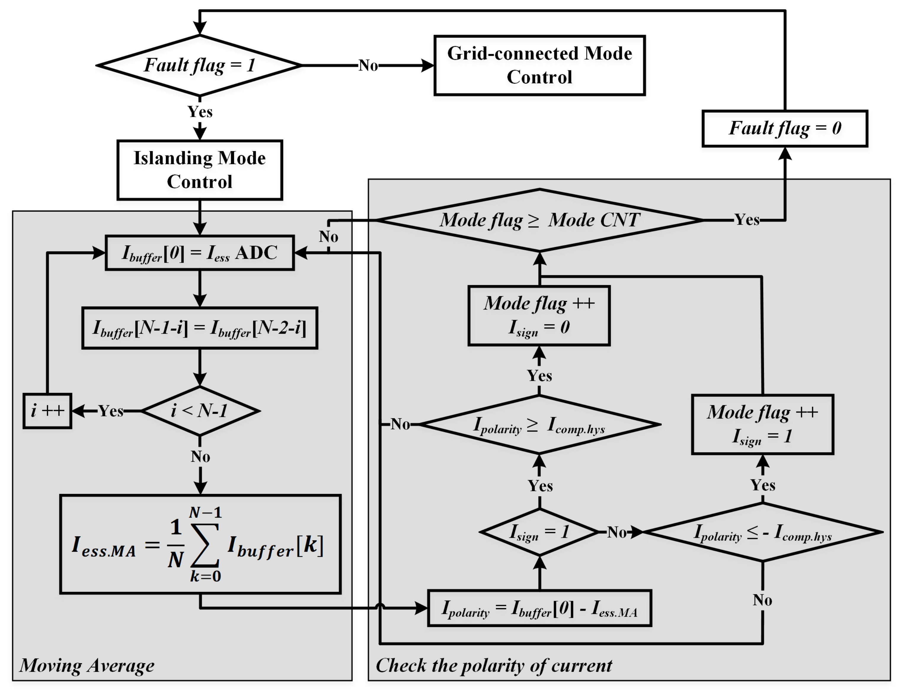
Figure 6 shows a flowchart of the recovery control algorithm in the ESS converter. In islanding mode, the ESS converter continuously samples N number of data () and sequentially moves the collected data to the next data buffer, shown in Equation (2).
From Equation (2), the new current data of the ESS converter is continually added to the N number of data, and reflecting is sequentially calculated from Equation (3).
When the present state current changes rapidly, since there is a difference between and , the ESS converter compares and to determine the polarity of the current () (Equation (4)). is used to distinguish the information of the grid state in the power line communication.
Because the AC/DC converter continuously supplies the specific patterned current until the ESS converter recognizes it, the ESS converter can identify the continuous polarity change of . The is compared with a reference value applied to hysteresis to improve the accuracy of polarity detection, as shown in Figure 6. If the polarity of is continuously positive and negative, as many as the user-specified count (Mode CNT), the ESS converter will determine that the AC grid is restored and the AC/DC converter is connected to the DC-bus simultaneously. When the ESS converter recognizes this patterned current, its operation mode is changed from voltage source mode for regulating the DC-bus voltage to current source mode for charging and discharging the battery. Then, the DC-bus voltage decreases to the voltage level of because of the power consumption of the DC load. By measuring this fluctuation of the DC-bus voltage, the operation mode of the AC/DC converter is changed from current source mode for generating the specific patterned current to voltage source mode for regulating the DC-bus voltage, which means the grid-connected mode returns. When the ESS converter checks the current of the specific pattern and switches from islanding mode to grid-connected mode, if the DC load is less than the power generation from the renewable energy source, the DC-bus voltage will not drop to , but rather increase to or more. If the DC-bus voltage continuously increases above , the DC-bus protector will operate to make voltage less than .
4. Simulation and Experimental Results
4.1. Control Strategy Verification Using Simulation Results
This paper uses the PSIM simulation tool (Version 10.0.6.564, POWERSIM, Rockville, MD, USA). Figure 7 describes the simulation setup of the proposed 380 V DC microgrid test bed. The capacitance affecting the change in DC-bus voltage and simulation parameters of each power converter is set to be the same as in the experimental conditions shown in Appendix A to obtain experimental results closest to the simulation results.
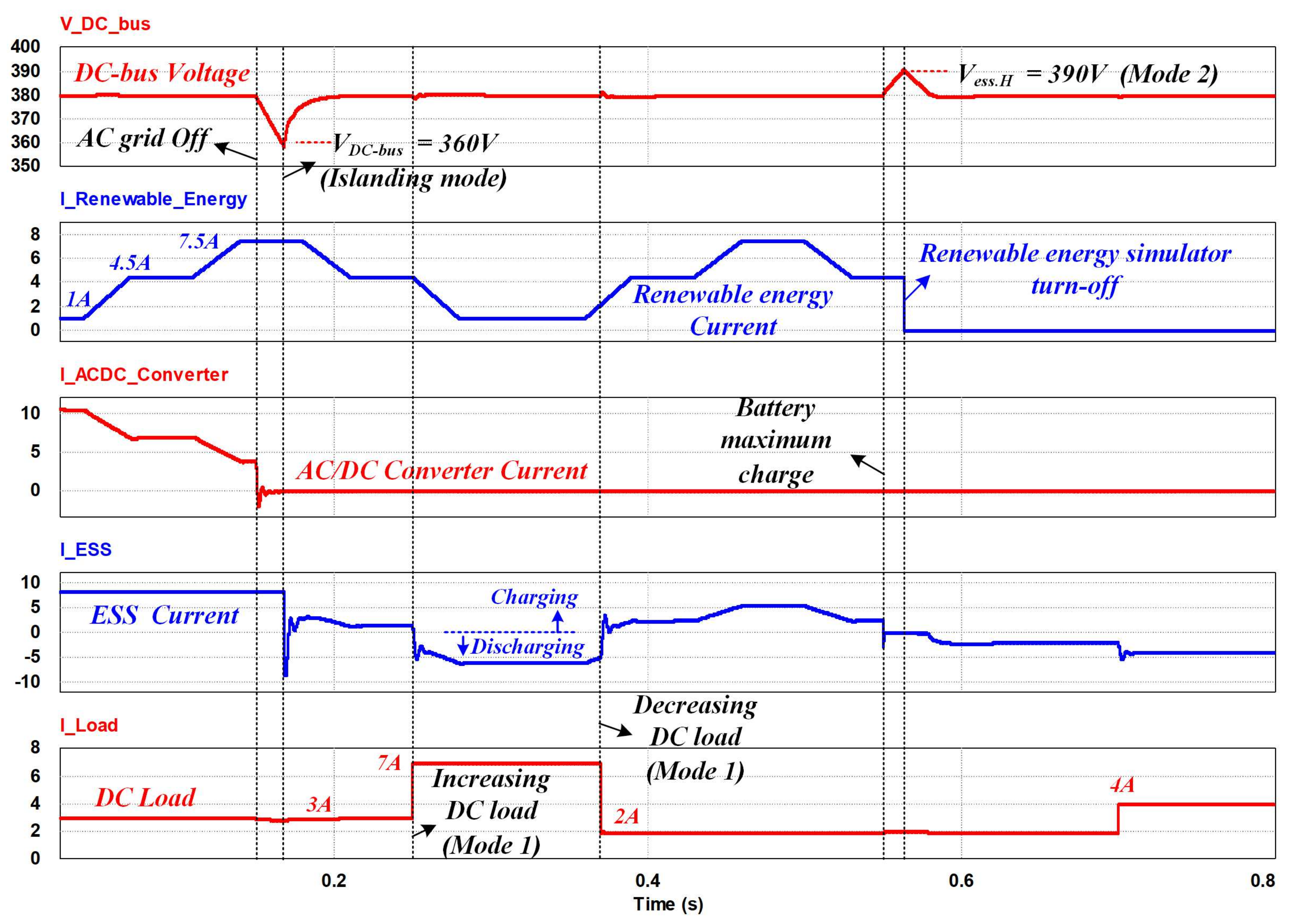
The proposed simulation model is designed to simulate islanding mode, which operates without DC-bus voltage regulation by the AC/DC converter. In the simulation results, several modes are verified according to the DC-bus voltage levels presented in the proposed power management algorithm. When the DC-bus voltage falls below for the first time due to AC/DC converter and/or AC grid faults, the ESS converter will regulate the DC-bus voltage by changing its control algorithm from current control to voltage control in islanding mode, as shown in Figure 8.
Figure 8 describes mode 1 and 2. According to the mode 1, the ESS converter controls the DC-bus voltage within the range of to . The battery is charged by the extra power through the ESS converter while the power consumption of the DC load is less than the power generation from the renewable energy simulator. When the DC load increases, the generated power is lower than the power consumption in the DC load. At that time, the ESS converter changes its operation from charging to discharging mode because of insufficient electric power. When the power consumption of the DC load is less than the power generation of the renewable energy simulator, and if the ESS battery is fully charged, the DC-bus voltage rises to , because the ESS converter can no longer regulate the DC-bus voltage, which gradually limits the charging current. In order to prevent the DC-bus voltage from rising abnormally, the renewable energy system is stopped, as shown in Figure 8, which defines mode 2. Then, according to mode 1, the ESS converter regulates the DC-bus voltage by discharging the ESS battery.
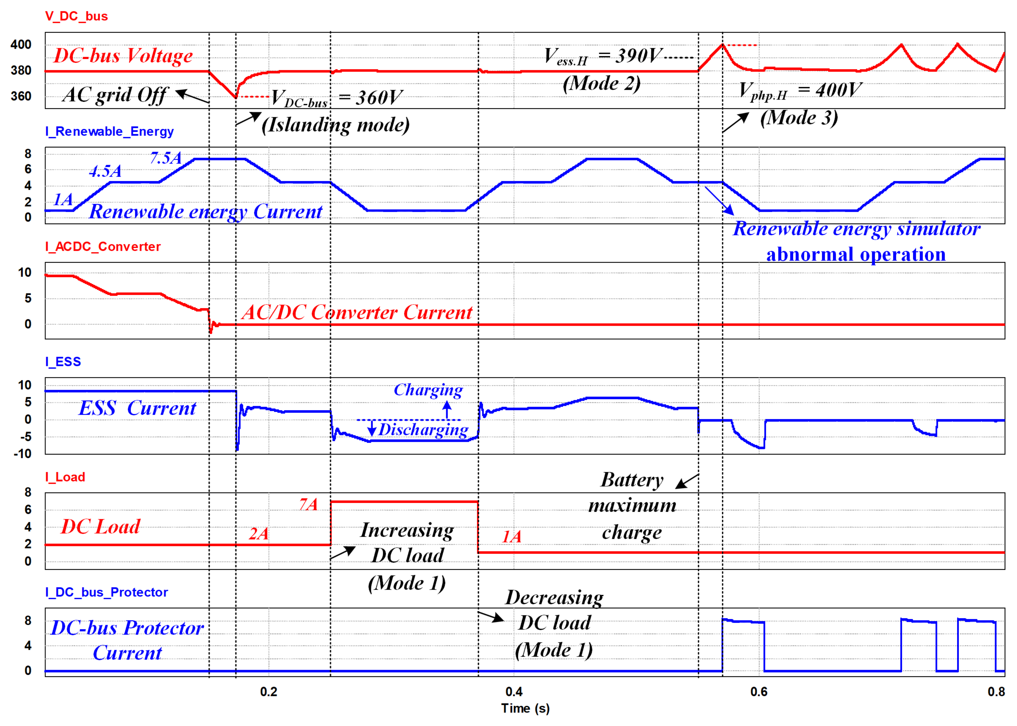
Figure 9 shows that the ESS converter changes its charging or discharging mode according to the transition of the DC load. In mode 2, if the renewable energy system operates abnormally, which means it cannot be stopped when the DC-bus voltage rises to , the DC-bus voltage rises to due to the power generation of the renewable energy system. In mode 3, the DC-bus protector is activated to protect the DC microgrid, decreasing the DC-bus voltage to , as shown in Figure 9. When the DC-bus voltage drops below , the DC-bus protector stops its operation. Then, the DC-bus voltage repeatedly increases and decreases in the mode 3.
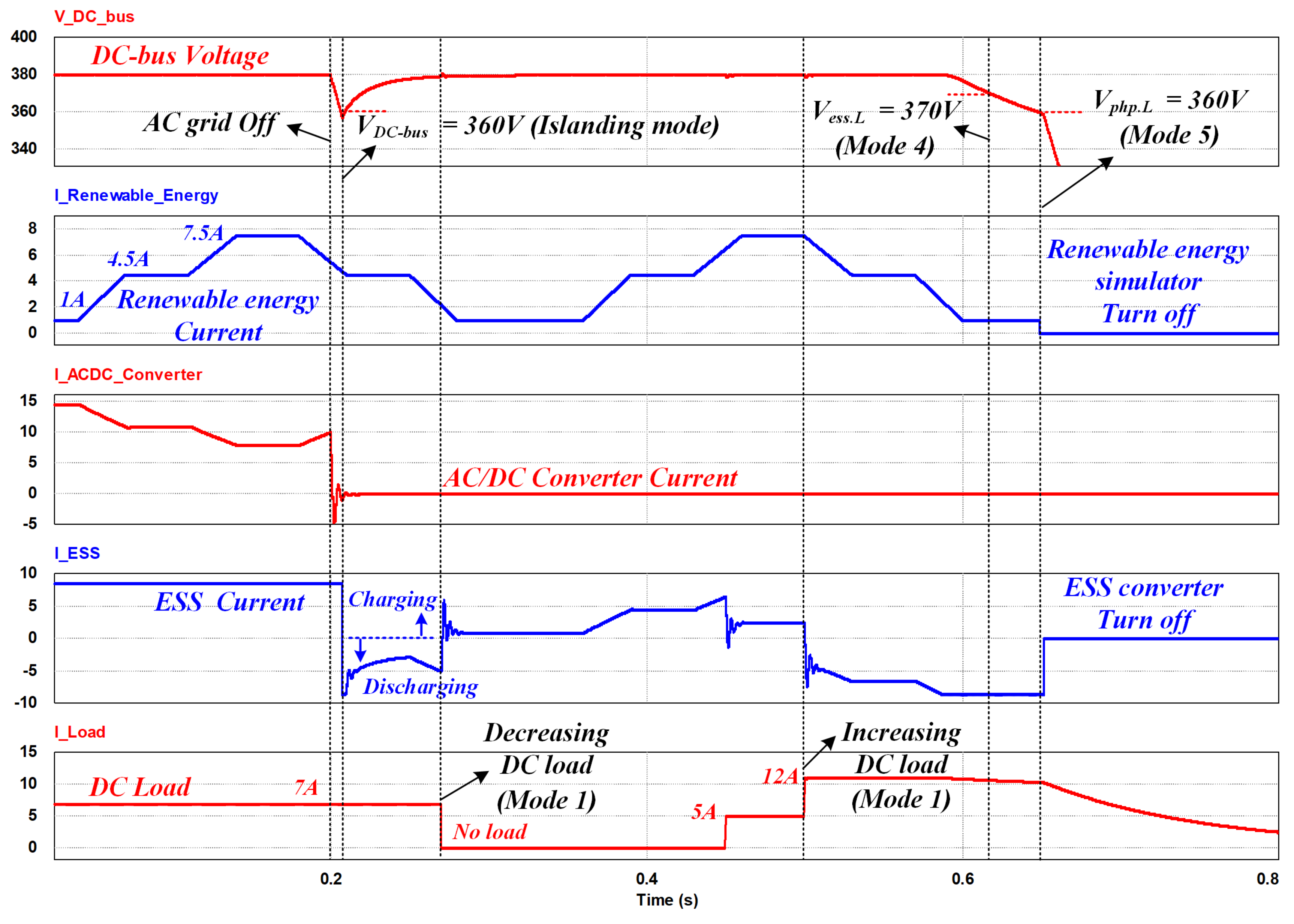
Figure 10 shows modes 1, 4, and 5. In mode 4, if the power consumption in the DC load is larger than the power generation and power dissipation from the renewable energy source and the ESS battery, the DC-bus voltage will drop below . In Figure 10, the ESS converter discharges the battery to the maximum in mode 4. At that time, the DC-bus voltage is continuously decreased to less than due to the power shortage. When the DC-bus voltage drops below , in mode 5, the entire DC microgrid system stops and all the grid components are disconnected from the DC-bus for their protection, which is simulated in Figure 10.
Figure 11 shows the proposed autonomous operation of the DC microgrid according to AC grid conditions. In grid-connected mode, the AC/DC converter regulates the DC-bus voltage. First, the ESS converter charges the battery. If the DC-bus voltage falls below due to AC grid faults, the ESS converter will regulate the DC-bus voltage in islanding mode. When the AC grid is restored, the AC/DC converter continuously supplies current to the DC-bus with specific patterns, as shown in Figure 11. The current pattern generated from the AC/DC converter has the effect of generating a similarly shaped current pattern in the ESS converter. By using the moving average method proposed in Figure 6, the ESS converter recognizes the special current pattern independent of load variation and supplied current from the renewable energy source, as shown in Figure 11. When the ESS converter detects this current pattern, its operation mode changes from regulating DC-bus voltage to charging the battery. Then, the DC-bus voltage decreases under , due to the DC load. Since the AC/DC converter can recognize this DC-bus voltage collapse, its operation mode changes from current control with a specific pattern to voltage control for regulating DC-bus voltage in grid-connected mode.
4.2. Experimental Results Using DC Microgrid Test-Bed
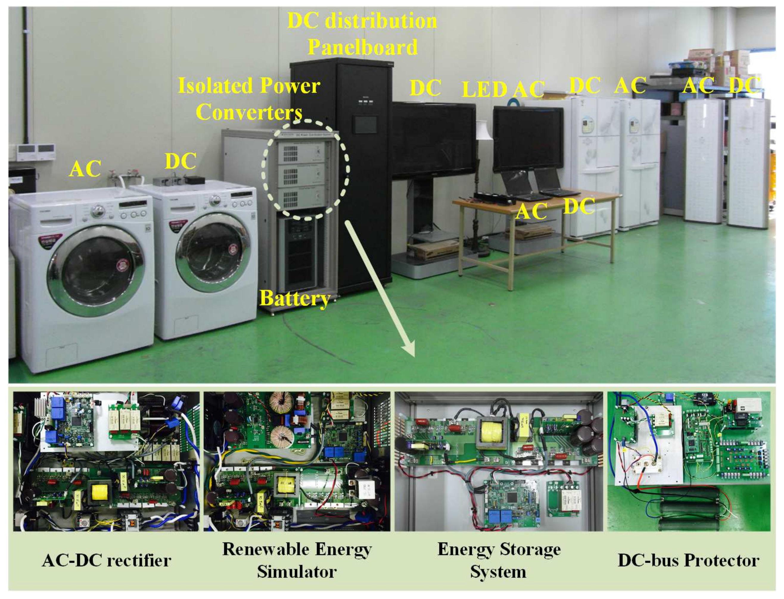
The DC microgrid test bed, including the proposed power management algorithm, is implemented as shown in Figure 12. It is composed of a bidirectional AC/DC converter, a renewable energy simulator, an ESS, a DC distribution panel board, a DC plug, AC home appliances, DC home appliances, and a DC-bus protector. The bidirectional AC/DC converter connects the AC grid and DC microgrid, and all other converters are connected parallel to the DC microgrid, except the DC distribution panel board, which is series connected to the microgrid to distribute DC power to all the components.
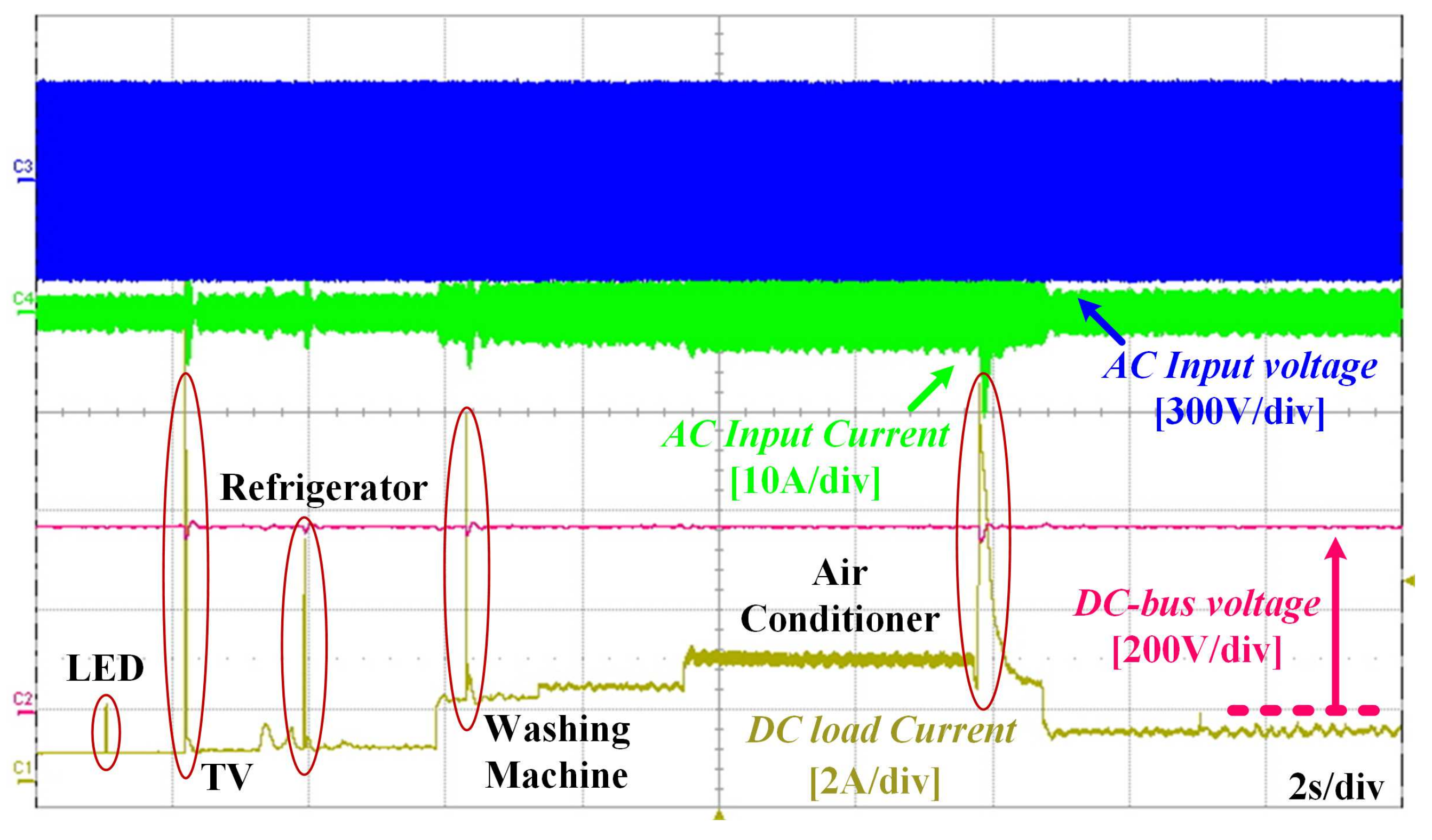
Figure 13 shows the steady-state operation of the prototype 380 V DC microgrid interfaced with DC home appliances in grid-connected mode. When the DC loads are connected to the DC-bus using a DC contactor, the inrush current is caused by their inside capacitors.
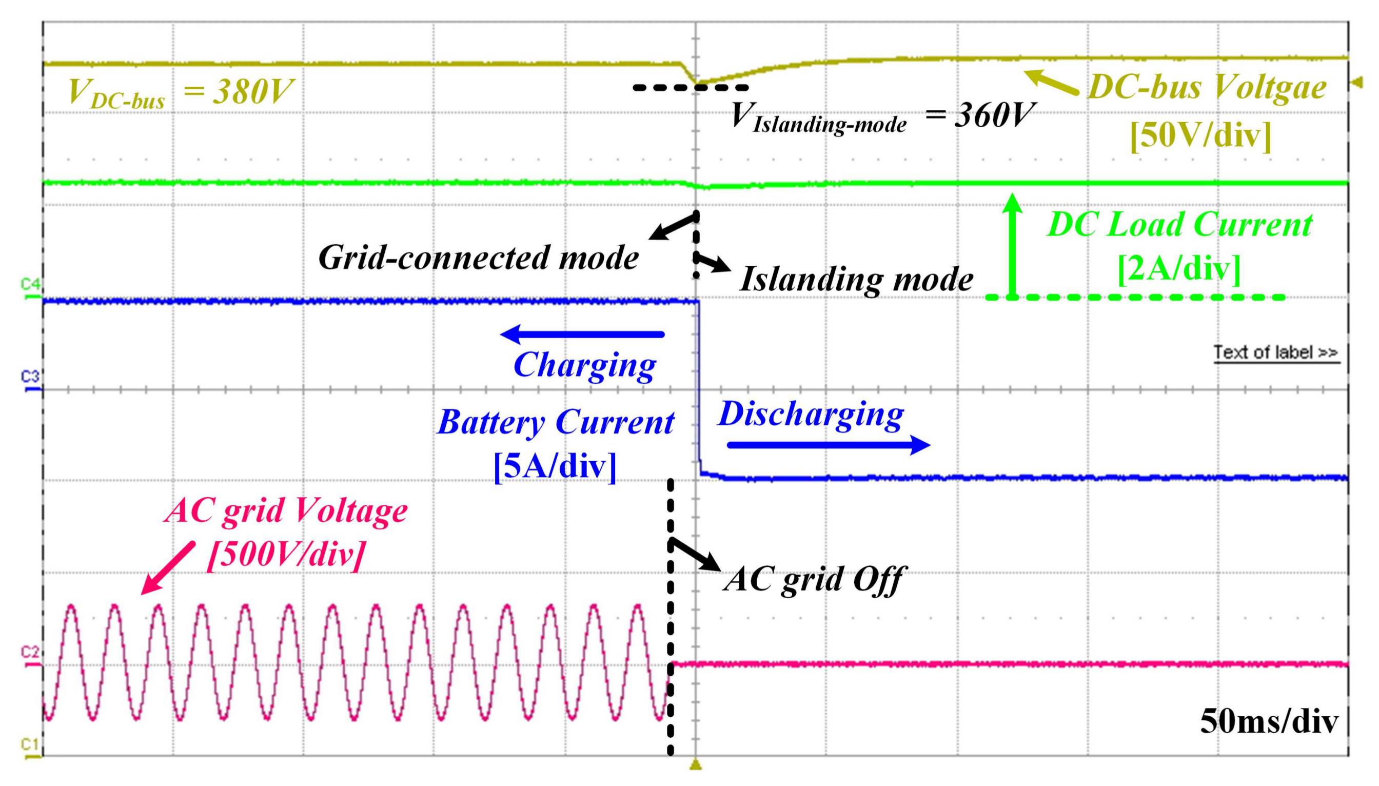
Figure 14 shows experimental waveforms for the test-bed system changing from grid-connected mode to islanding mode due to the AC grid being turned off. In grid-connected mode, the AC/DC converter regulates the DC-bus voltage to and the ESS battery is charged by 5 A current supplied from the AC/DC converter. When the AC grid shuts down abnormally, the DC-bus voltage collapses to before entering islanding mode. Then, to compensate for this voltage collapse, the ESS converter regulates the DC-bus voltage to by discharging electric power from the battery during islanding mode, which is shown in Figure 14.
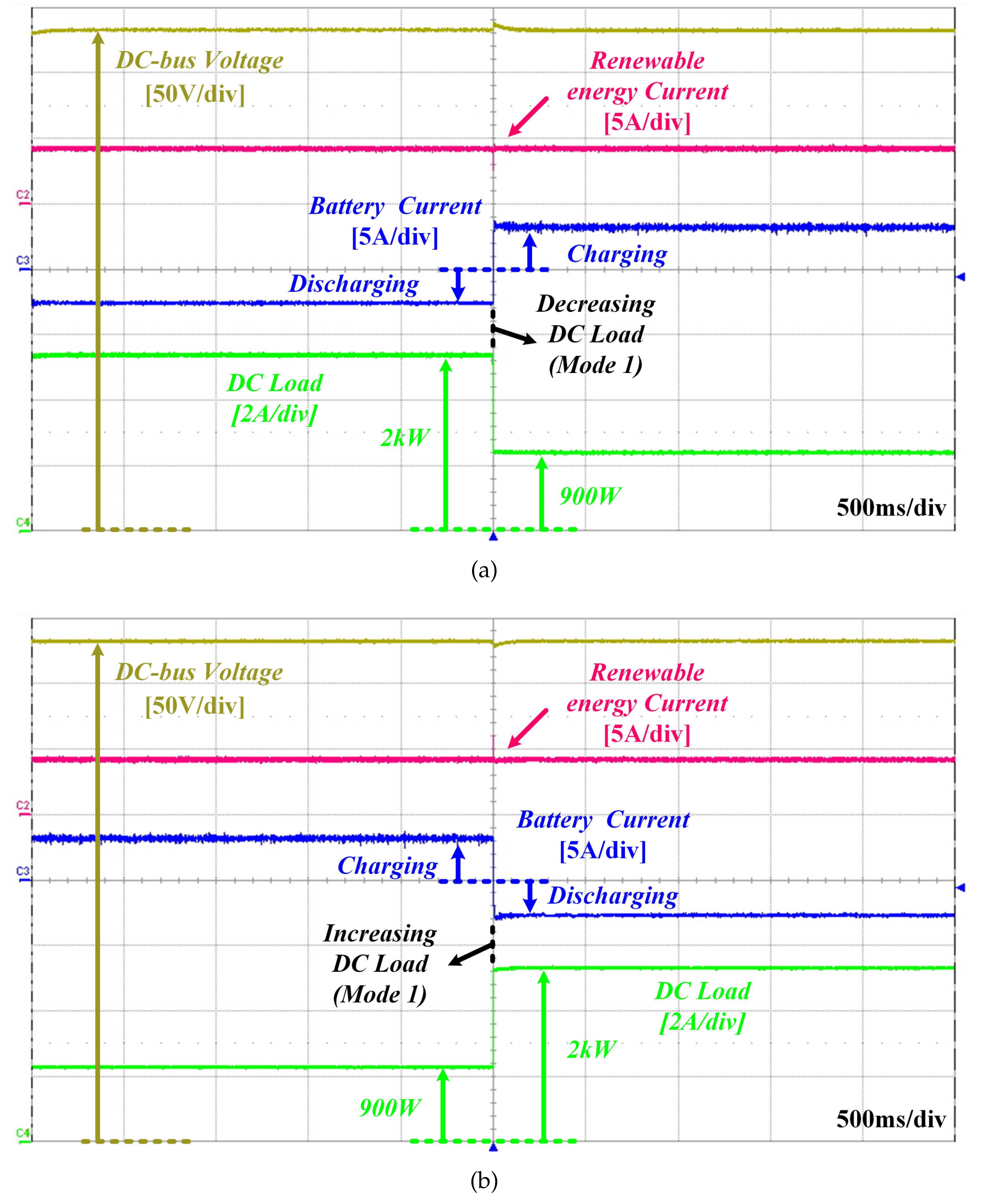
In islanding mode, the experimental results were tested based on Table 1, which shows the operation mode according to the DC-bus voltage band. The ESS converter regulates the DC-bus voltage such that the renewable energy simulator, DC protector, and DC loads operate properly during islanding mode. In mode 1, when the power consumption of the DC load is less than the power generation of the renewable energy simulator, the ESS converter changes from discharging mode to charging mode because of the increased DC-bus voltage, as shown in Figure 15a. The renewable energy simulator supplies 4 A current, which generates 1.5 kW power in the DC microgrid. As the DC load is 2 kW, the ESS converter supplies insufficient power of 500 W by discharging the battery. When the DC load decreases from 2 kW to 900 W, 600 W electric power remains in the DC microgrid, which increases the DC-bus voltage level. To regulate the DC-bus voltage, operation of the ESS converter changes from discharging mode to charging mode. Then, the 600 W of remaining power can be transferred to the battery without the DC-bus voltage increment. In contrast, when load power consumption is higher than the power generated from the renewable energy simulator, the ESS converter changes from charging mode to discharging mode to increase the power discharged from the battery, as shown in Figure 15b. The renewable energy simulator generates 4 A, which supplies 1.5 kW to the DC microgrid. When 900 W power is consumed by the DC load, the remaining 600 W power should be discharged from the battery through the ESS converter. When the DC load is increased from 900 W to 2 kW, the DC-bus voltage decreases even if all of the 1.5 kW electric power generated from the renewable energy simulator supplies the DC load because of the insufficient 500 W. Since the ESS converter can regulate the DC-bus voltage by using its bidirectional power control ability, it supplies the insufficient 500 W power from the battery to the DC microgrid.
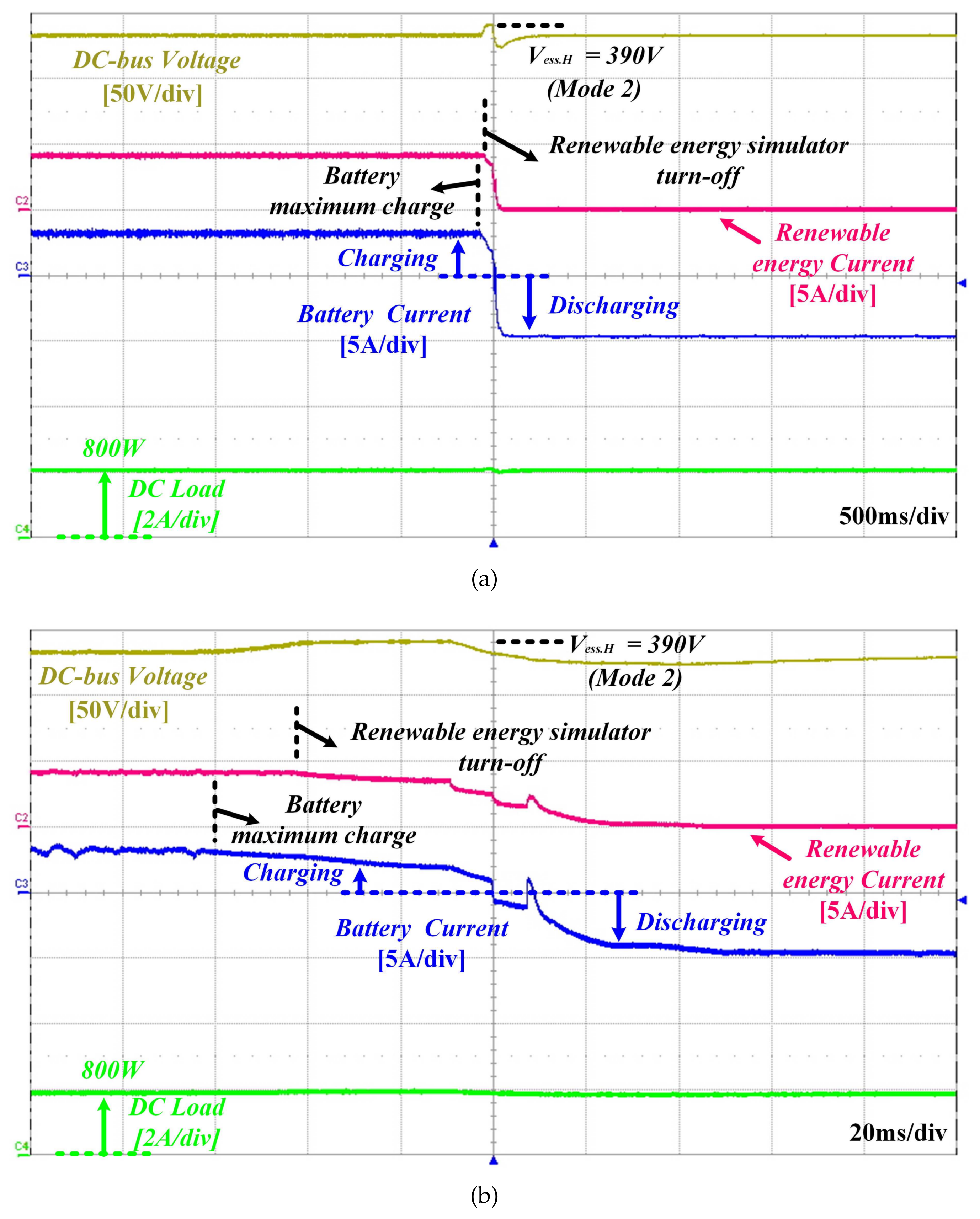
In mode 2, since the battery is fully charged, the ESS converter gradually limits the charging current. The renewable energy simulator continuously generates 4 A current which supplies 1.5 kW power to the DC microgrid. The DC-bus voltage is increased by the remaining 700 W power because the DC load is at most 800 W. When the DC-bus voltage rises to , the renewable energy simulator stops its power generation, which is illustrated in Table 1. Then, mode 2 follows mode 1, which means that the ESS converter changes its operation to discharging mode to regulate the DC-bus voltage, as shown in Figure 16. Figure 16a shows the experimental results of 500 ms/div. For more details, Figure 16b shows the experimental result of 50 ms/div.
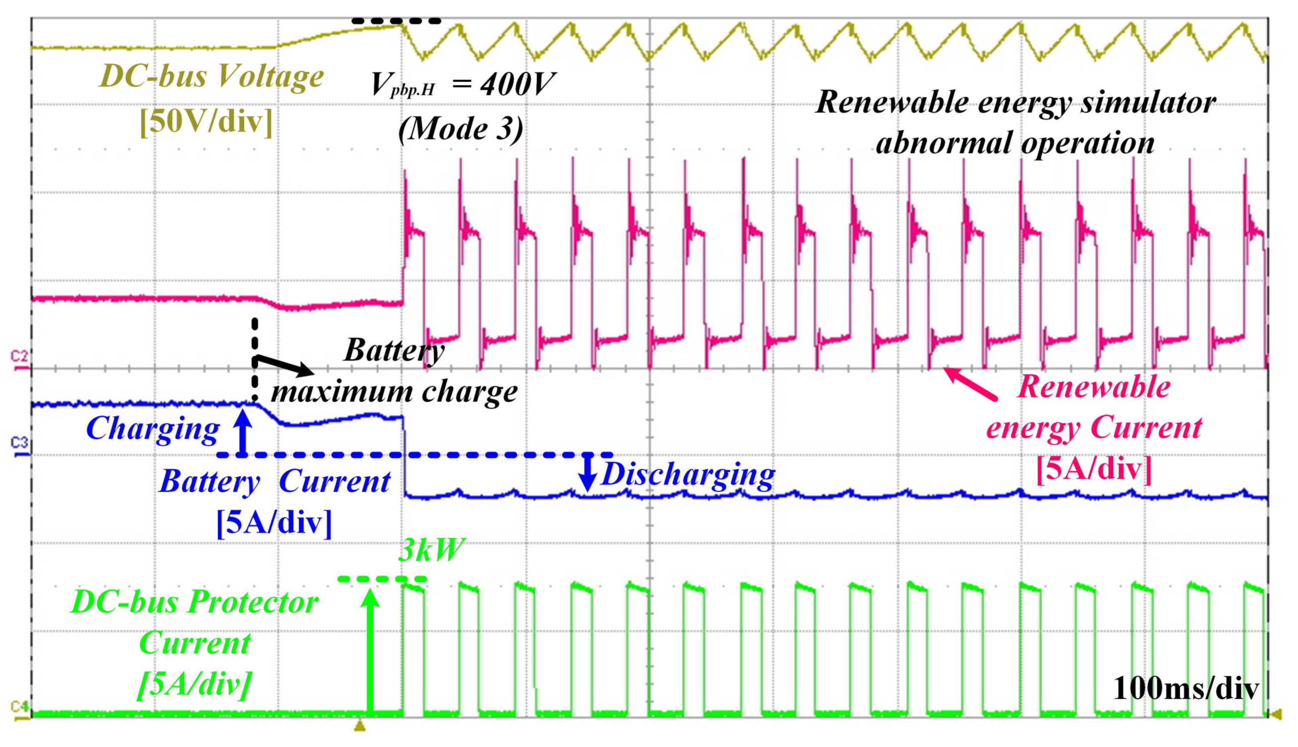
In mode 3, the battery and the ESS converter are in the same situation as in mode 2. If the renewable energy source cannot stop at , which assumes a malfunction, the DC-bus voltage increases to because of the 4 A current supply from the renewable energy simulator. The DC-bus protector consists of an IGBT and 3 kW resistors, which suppresses the DC-bus voltage when it goes higher than . The DC bus protector can consume electric power using the 3 kW resistors in this abnormal condition. When the DC-bus voltage decreases to lower than , the DC-bus protector stops its operation. Then, the DC-bus voltage repeatedly increases and decreases such that the DC-bus protector also repeatedly operates and stops, as shown in Figure 17.
Figure 17 shows a sudden collapse in the generated current from the renewable energy simulator, since it is implemented using the voltage source type DC/DC converter. In normal operation, if the DC-bus voltage reaches , the DC-bus protector will operate to protect the DC microgrid from overvoltage hazard. At that time, the renewable energy simulator continuously supplies generated current to the DC load and DC-bus protector, which is more than 3 kW. In addition, insufficient electric power caused by power consumption of the DC load and the DC-bus protector is supplied by discharging the battery. Figure 17, on the other hand, shows that the generated current from the renewable energy simulator suddenly collapses when the DC bus protector turns off, since the renewable energy simulator is implemented using the voltage source type topology, the LLC resonant converter. In normal operation, the renewable energy source is designed as a current source. However, the practical renewable energy simulator consists of the voltage source type LLC resonant converter and an inductor used as a power interface between the DC-bus and the output stage of the converter. When the DC-bus voltage increases to , the output voltage of the renewable energy simulator also increases over to generate a constant output current of 4 A. The reduced DC-bus voltage instantaneously induces high current caused by a high voltage difference between the DC-bus voltage and the output voltage of the renewable energy simulator. Since the proposed renewable energy simulator is not an ideal current source, there is current fluctuation of simulator, as shown in Figure 17.
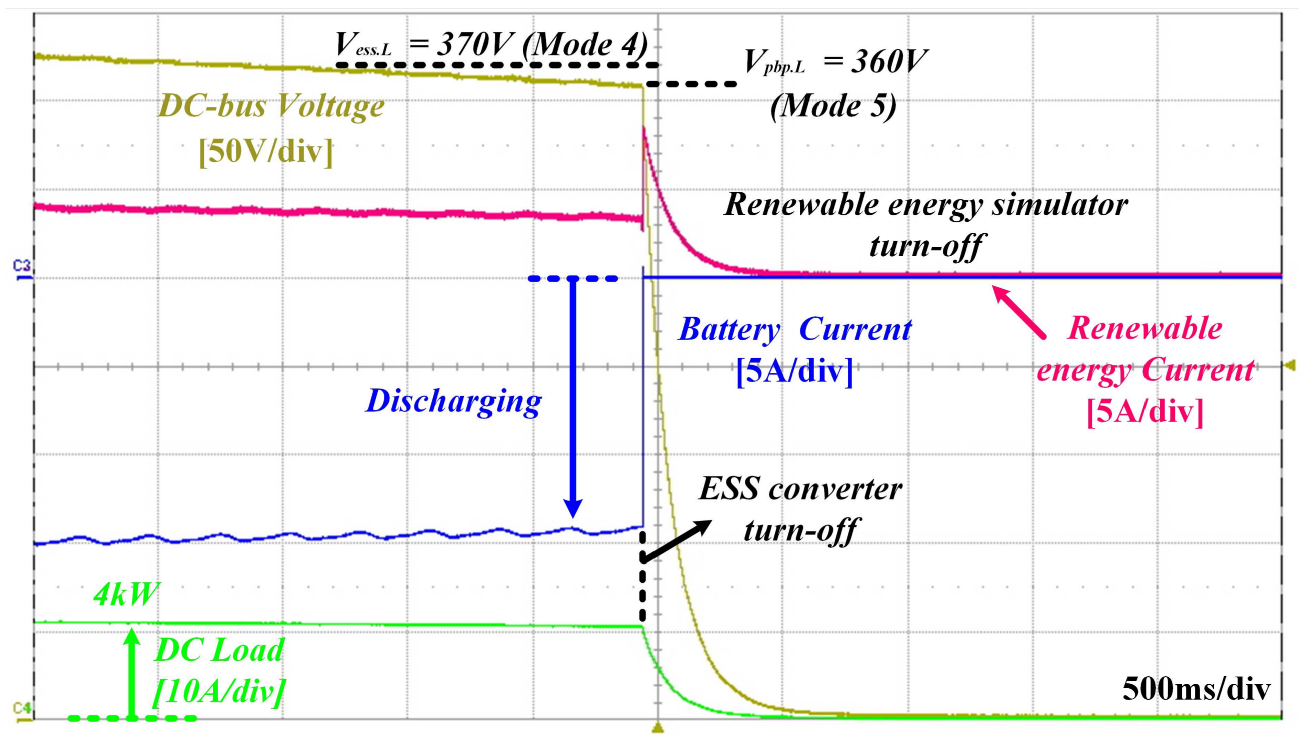
The power consumption of the DC load is larger than the entire power generation of the renewable energy and the battery. Figure 18 shows that the power consumption of the DC load is larger than 4 kW, and the current supply of the renewable energy simulator gradually decreases from 4 A to 3 A. At that time, the ESS converter fully discharges the battery. However, the DC-bus voltage continues to decrease below due to overload, which defines mode 4. As shown in Figure 18, since the DC load is not reduced and the amount of power generated by renewable energy does not increased, the DC-bus voltage continuously decreases to . According to the mode 5, the entire DC microgrid system stops and turns off, and all the grid components are disconnected for their protection.
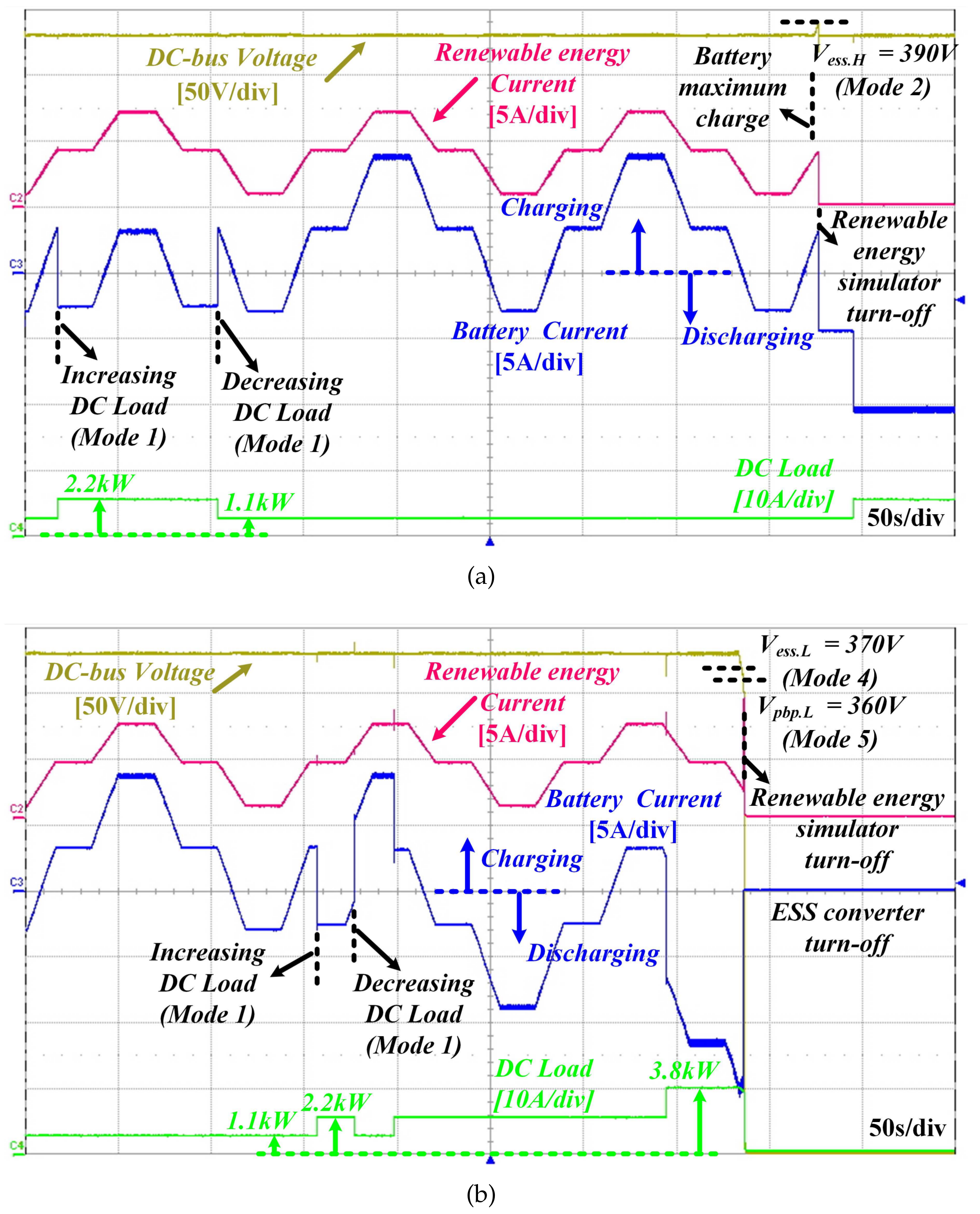
Figure 19 shows the experimental waveforms of autonomous operation in modes 1, 2, 4, and 5 in islanding mode. Figure 19a shows the operation of the mode 1. The ESS converter operates under charging or discharging mode, which can regulate the DC-bus voltage described in mode 1. In addition, according to the sequence of mode 2, if the battery is fully charged, the renewable energy simulator will stop at the DC-bus voltage of and the ESS converter will regulate the DC-bus voltage under discharging mode, described in mode 2, as shown in Figure 19a. Similarly, Figure 19b shows the operational modes 1, 4, and 5. However, the power consumption of the DC load is larger than the entire power generation of the renewable energy and the battery. The DC-bus voltage continuously drops to and enters mode 4. The DC-bus voltage steadily decreases, because there is no decrease in DC load or increase in power generation. Then, when the DC-bus voltage decreases below , the entire DC microgrid system stops to protect the DC microgrid itself, which is described in mode 5.
Figure 20 describes the experimental results of the autonomous operation of the DC microgrid system according to AC grid conditions. In islanding mode, the ESS converter controls the power flow instead of the AC/DC converter. When the AC grid is restored, the AC/DC converter continuously resumes to supply the patterned current, as shown in Figure 20. The proposed current pattern is configured as a square wave of the specific current pattern having 3 A , 0.5 duty, and a 1 s period. When the ESS converter detects this current pattern, its operation mode changes from regulating the DC-bus voltage to charging the battery. Then, the DC-bus voltage decreases under due to the DC load. Since the AC/DC converter recognizes the collapsibility of the DC-bus voltage, its operation mode is changed from current source to voltage source to regulate DC-bus voltage in grid-connected operation.
5. Conclusions
This paper proposes the autonomous DC microgrid operation to maintain the DC microgrid stably according to the AC grid status. In entering islanding mode, the DBS method using DC-bus voltage band was applied, and the ESS converter controlled the DC-bus voltage by charging and discharging the battery to maintain power balance. In addition, several modes for the DC-bus voltage band were considered to verify that the proposed power management algorithm properly operated in islanding mode. When the AC grid returned to normal, since the DBS method was not sufficient to make a decision to reenter grid-connected mode from islanding mode, the recovery control strategy was proposed using the specific current pattern and moving average in power line communication. The proposed autonomous power management with specific current pattern was implemented on a DC microgrid test bed and experimentally verified under various operating modes. Simulation and experimental results show the functionality and performance of the proposed algorithm in islanding mode. In addition, results show that the proposed recovery control strategy also operates normally in the DC microgrid test bed system according to the AC grid status.
Acknowledgments
This research was supported by Korea Electrotechnology Research Institute(KERI) Primary research program through the National Research Council of Science & Technology(NST) funded by the Ministry of Science and ICT (MSIT)(No. 18-12-N0101-03).
Author Contributions
Dong-Keun Jeong, Hee-Je Kim and Jee-Hoon Jung conceptualized the idea of this research project. Dong-Keun Jeong, Ho-Sung Kim and Ju-Won Baek designed the structure and components of DC microgrid test bed. Ho-Sung Kim designed a DSP controller board. Dong-Keun Jeong and Ho-Sung Kim developed the control algorithm and DSP program of components. Dong-Keun Jeong made an experimental setup and did experiment. The data was analyzed by the team and the paper was written by Dong-Keun Jeong, Hee-Je Kim and Jee-Hoon Jung.
Conflicts of Interest
The authors declare no conflict of interest.
Appendix A. Design Specifications of System Component in DC Microgrid

Table A1.
Design Specifications of Isolated AC/DC Converter.
| AC/DC Converter | DAB Converter | ||
|---|---|---|---|
| Input Voltage | AC 220 | Input Voltage | 380 V |
| Output Voltage | 380 V | Output Voltage | 380 V |
| Rated Power | 5 kW | Rated Power | 5 kW |
| Switching Frequency | 13.8 kHz | Switching Frequency | 50 kHz |
| Filter Inductance | 1.6 mH | inductance | 69 H |
| Output Capacitors | 2.7 mF | Transformer turn ratio | 1:1 |
| Output Capacitors | 2 mF | ||
Table A2.
Design Specifications of ESS.
| DAB Converter | |
|---|---|
| Input battery Voltage | 150∼200 V |
| Output Voltage | 380 V |
| Rated Power | 3 kW |
| Switching Frequency | 50 kHz |
| Transformer turn ratio | 1:0.53 |
| Coupling inductance(Lm) | 31 H |
| Output Capacitors | 1.3 mF |
Table A3.
Design Specifications of Renewable Energy Simulator.
| Bridgeless PFC Boost Rectifier | LLC Resonant Converter | ||
|---|---|---|---|
| Input Voltage | AC 220 | Input Voltage | 380 V |
| Output Voltage | 380 V | Output Voltage | 380 V |
| Rated Power | 3.3 kW | Rated Power | 3 kW |
| Switching Frequency | 50 kHz | Switching Frequency | 55∼60 kHz |
| Filter Inductance | 680 H | Transformer turn ratio | 1:0.9 |
| Output Capacitors | 2 mF | Magnetizing inductance(Lm) | 250 H |
| Resonant inductance(Lr) | 50 H | ||
| Resonant Capacitance(Cr) | 141 nF | ||
| Output Capacitors | 2 mF | ||
References
- Riad, C.; Saifur, R. Unit sizing and control of hybrid wind-solar power systems. IEEE Trans. Energy Convers. 1997, 12, 79–85. [Google Scholar]
- Walter, D.; Mariacristina, R.; Dario, Z. Hybrid photovoltaic system control for enhancing sustainable energy. In Proceedings of the IEEE Power Engineering Society Summer Meeting, Chicago, IL, USA, USA, 21–25 July 2002; Volume 1, pp. 134–139. [Google Scholar]
- Masato, K.; Masato, M. Experimental study of 380 Vdc power distribution system with wind-power-generation. In Proceedings of the IEEE 34th International Telecommunications Energy Conference (INTELEC), Scottsdale, AZ, USA, 30 September–4 October 2012; pp. 1–4. [Google Scholar]
- Wu, T.-F.; Chang, C.-H.; Lin, L.-C.; Yu, G.-R.; Chang, Y.-R. DC-bus voltage control with a three-phase bidirectional inverter for DC distribution systems. IEEE Trans. Power Electron. 2013, 28, 1890–1899. [Google Scholar] [CrossRef]
- Hiroaki, K.; Yushi, M.; Toshifumi, I. Low-voltage bipolar-type DC microgrid for super high quality distribution. IEEE Trans. Power Electron. 2010, 25, 3066–3075. [Google Scholar]
- Guy, A.; William, T. DC-bus voltage control with a three-phase bidirectional inverter for DC distribution systems. IEEE Power Energy Mag. 2012, 10, 50–59. [Google Scholar]
- Lee, J.; Han, B.; Choi, N. DC micro-grid operational analysis with detailed simulation model for distributed generation. In Proceedings of the IEEE Energy Conversion Congress and Exposition, Atlanta, GA, USA, 12–16 September 2010; pp. 3153–3160. [Google Scholar]
- Faridaddin, K.; Reza, I.M. Power management strategies for a microgrid with multiple distributed generation units. IEEE Trans. Power Syst. 2006, 21, 1821–1831. [Google Scholar]
- Chen, D.; Xu, L. DC microgrid with variable generations and energy storage. In Proceedings of the IET Conference on Renewable Power Generation, Edinburgh, UK, 6–8 September 2011; pp. 1–6. [Google Scholar]
- Zhang, H.; Mollet, F.; Saudemont, C.; Robyns, B. Experimental validation of energy storage system management strategies for a local dc distribution system of more electric aircraft. IEEE Trans. Ind. Electron. 2010, 57, 3905–3916. [Google Scholar] [CrossRef]
- Ryu, M.; Kim, H.; Baek, J.; Kim, H.; Jung, J. Effective Test Bed of 380 V DC Distribution System using Isolated Power Converters. IEEE Trans. Ind. Electron. 2015, 62, 4525–4536. [Google Scholar] [CrossRef]
- Zhang, Y.; Jiang, Z.; Yu, X. Control strategies for battery/supercapacitor hybrid energy storage systems. In Proceedings of the IEEE Energy 2030 Conference, Atlanta, GA, USA, 17–18 November 2008; pp. 1–6. [Google Scholar]
- Jiang, W.; Babak, F. Active current sharing and source management in fuel cell-battery hybrid power system. IEEE Trans. Ind. Electron. 2010, 57, 752–761. [Google Scholar] [CrossRef]
- Schönberger, J.; Duke, R.; Round, S.D. DC-Bus Signaling: A Distributed Control Strategy for a Hybrid Renewable Nanogrid. IEEE Trans. Ind. Electron. 2006, 53, 1453–1460. [Google Scholar] [CrossRef]
- Lu, X.; Sun, K.; Guerrero, J.M.; Vasquez, J.C.; Huang, L. State-of-charge balance using adaptive droop control for distributed energy storage systems in DC microgrid applications. IEEE Trans. Ind. Electron. 2014, 61, 2804–2815. [Google Scholar] [CrossRef]
- Choi, H.J.; Jung, J.H. Enhanced power line communication strategy for DC microgrids using switching frequency modulation of power converters. IEEE Trans. Power Electron. 2017, 4140–4144. [Google Scholar] [CrossRef]
- Sun, K.; Zhang, L.; Xing, Y.; Guerrero, J.M. A Distributed Control Strategy Based on DC Bus Signaling for Modular Photovoltaic Generation Systems With Battery Energy Storage. IEEE Trans. Power Electron. 2011, 26, 3032–3045. [Google Scholar] [CrossRef]
- Xiao, J.; Wang, P. Multiple modes control of household DC microgrid with integration of various renewable energy sources. In Proceedings of the Industrial Electronics Society, IECON 2013, Vienna, Austria, 10–13 November 2013; pp. 1773–1778. [Google Scholar]
- Yu, X.; She, X.; Zhou, X.; Huang, A.Q. Power Management for DC Microgrid Enabled by Solid-State Transformer. IEEE Trans. Smart Grid 2013, 5, 954–965. [Google Scholar] [CrossRef]
- Kim, H.; Ryu, M.; Baek, J.; Jung, J. High-Efficiency Isolated Bidirectional AC-DC Converter for a DC Distribution System. IEEE Trans. Power Electron. 2013, 28, 1642–1654. [Google Scholar] [CrossRef]
- Naayagi, R.T.; Forsyth, A.J.; Shuttleworth, R. High-power bidirectional dc-dc converter for aerospace applications. IEEE Trans. Power Electron. 2012, 27, 4366–4379. [Google Scholar] [CrossRef]
- Kheraluwala, M.N.; Gascoigne, R.W.; Divan, D.M.; Baumann, E.D. Performance characterization of a high-power dual active bridge DC-to- DC converter. IEEE Trans. Ind. Appl. 1992, 28, 1294–1301. [Google Scholar] [CrossRef]
- Inoue, S.; Akagi, H. A bidirectional dc-dc converter for an energy storage system with galvanic isolation. IEEE Trans. Power Electron. 2007, 22, 2299–2306. [Google Scholar] [CrossRef]
- Tan, N.M.L.; Abe, T.; Akagi, H. Design and Performance of a Bidirectional Isolated DC-DC Converter for a Battery Energy Storage System. IEEE Trans. Power Electron. 2012, 27, 1237–1248. [Google Scholar] [CrossRef]
- Krismer, F.; Kolar, J.W. Efficiency-optimized high-current dual active bridge converter for automotive applications. IEEE Trans. Ind. Electron. 2012, 59, 2745–2760. [Google Scholar] [CrossRef]
- Jeong, D.; Ryu, M.; Kim, H.; Kim, H. Optimized design of bidirectional dual active bridge converter for low voltage battery charger. J. Power Electron. 2014, 14, 468–477. [Google Scholar] [CrossRef]
- Huber, L.; Jang, Y.; Jovanovic, M.M. Performance evaluation of bridgeless PFC boost rectifiers. IEEE Trans. Power Electron. 2008, 23, 1381–1390. [Google Scholar] [CrossRef]
- Yang, B.; Lee, F.C.; Zhang, A.J.; Huang, G. LLC resonant converter for front end DC/DC conversion. In Proceedings of the Applied Power Electronics Conference and Exposition, Dallas, TX, USA, 10–14 March 2002; Volume 2, pp. 1108–1112. [Google Scholar]
- Lu, B.; Liu, W.; Liang, Y.; Lee, F.C.; van Wyk, J.D. Optimal Design Methodology for LLC Resonant Converter. In Proceedings of the Applied Power Electronics Conference and Exposition, Dallas, TX, USA, 19–23 March 2006; pp. 533–538. [Google Scholar]
Figure 1.
Structure of a DC microgrid system.

Figure 2.
Configuration of electrical interface in the DC microgrid. (a) Grid-connected mode. (b) Islanding mode.
Figure 2.
Configuration of electrical interface in the DC microgrid. (a) Grid-connected mode. (b) Islanding mode.

Figure 3.
Graphical border lines according to DC voltage levles at islanding mode.

Figure 4.
State chart of the proposed power management algorithm in the islanding mode.

Figure 5.
The proposed recovery control strategy for changing the operation mode of the DC microgrid from the islanding mode to the grid-connected mode.
Figure 5.
The proposed recovery control strategy for changing the operation mode of the DC microgrid from the islanding mode to the grid-connected mode.

Figure 6.
Flow chart of the proposed ESS converter the recovery control for changing the operating mode of DC microgrid from islanding mode to grid-connection mode.
Figure 6.
Flow chart of the proposed ESS converter the recovery control for changing the operating mode of DC microgrid from islanding mode to grid-connection mode.

Figure 7.
Simulation Setup of the proposed 380V DC microgrid test-bed.

Figure 8.
Simulation waveforms of the proposed power management algorithm in islanding mode: Mode 1 and 2.
Figure 8.
Simulation waveforms of the proposed power management algorithm in islanding mode: Mode 1 and 2.

Figure 9.
Simulation waveforms of the proposed power management algorithm in islanding mode: Mode 1 and 3.
Figure 9.
Simulation waveforms of the proposed power management algorithm in islanding mode: Mode 1 and 3.

Figure 10.
Simulation waveforms of the proposed power management algorithm in islanding mode: Mode 1, 4 and 5.
Figure 10.
Simulation waveforms of the proposed power management algorithm in islanding mode: Mode 1, 4 and 5.

Figure 11.
Simulation waveforms of the proposed autonomous DC microgrid system according to AC grid condition.
Figure 11.
Simulation waveforms of the proposed autonomous DC microgrid system according to AC grid condition.

Figure 12.
Experimental Setup of the proposed prototype 380V DC microgrid test-bed.

Figure 13.
Experimental waveforms of the DC microgrid’s steady-states operation with DC home appliance in grid-connected mode.
Figure 13.
Experimental waveforms of the DC microgrid’s steady-states operation with DC home appliance in grid-connected mode.

Figure 14.
Experimental waveforms of entering islanding mode from grid-connected mode at AC grid off.
Figure 14.
Experimental waveforms of entering islanding mode from grid-connected mode at AC grid off.

Figure 15.
Experimental waveforms of autonomous operation at Mode 1: (a) Discharging to Charging. (b) Charging to Discharging.
Figure 15.
Experimental waveforms of autonomous operation at Mode 1: (a) Discharging to Charging. (b) Charging to Discharging.

Figure 16.
Experimental waveforms of autonomous operation at Mode 2: (a) 500 ms/div. (b) 20 ms/div.

Figure 17.
Experimental waveforms of autonomous operation: Mode 3.

Figure 18.
Experimental waveforms of autonomous operation: Mode 4 and 5.

Figure 19.
Experimental waveforms of autonomous operation: (a) Mode 1 and 2. (b) Mode 1, 4 and 5.

Figure 20.
Experimental waveforms of the re-entering the grid-connected mode from Islanding mode according to the AC grid condition.
Figure 20.
Experimental waveforms of the re-entering the grid-connected mode from Islanding mode according to the AC grid condition.

Table 1.
The proposed Operation Mode for Islanding Mode.
| DC-Bus Voltage | Energy Storage System | Renewable Energy Source | DC-Bus Protector | Mode |
|---|---|---|---|---|
| (400 V) | ON | OFF | ON | 3 |
| (390 V) | ON (Discharge) | OFF | OFF | 2 |
| (380 V) | ON (Charge/Discharge) | ON | OFF | 1 |
| (370 V) | ON (Discharge) | ON | OFF | 4 |
| (360 V) | OFF | OFF | OFF | 5 |
© 2018 by the authors. Licensee MDPI, Basel, Switzerland. This article is an open access article distributed under the terms and conditions of the Creative Commons Attribution (CC BY) license (http://creativecommons.org/licenses/by/4.0/).
Share and Cite
MDPI and ACS Style
Jeong, D.-K.; Kim, H.-S.; Baek, J.-W.; Kim, H.-J.; Jung, J.-H. Autonomous Control Strategy of DC Microgrid for Islanding Mode Using Power Line Communication. Energies 2018, 11, 924. https://doi.org/10.3390/en11040924
AMA Style
Jeong D-K, Kim H-S, Baek J-W, Kim H-J, Jung J-H. Autonomous Control Strategy of DC Microgrid for Islanding Mode Using Power Line Communication. Energies. 2018; 11(4):924. https://doi.org/10.3390/en11040924
Chicago/Turabian StyleJeong, Dong-Keun, Ho-Sung Kim, Ju-Won Baek, Hee-Je Kim, and Jee-Hoon Jung. 2018. "Autonomous Control Strategy of DC Microgrid for Islanding Mode Using Power Line Communication" Energies 11, no. 4: 924. https://doi.org/10.3390/en11040924
Note that from the first issue of 2016, this journal uses article numbers instead of page numbers. See further details here.