A New Approach of Minimizing Commutation Torque Ripple for BLDCM

1
Shaanxi Key Laboratory of Small & Special Electrical Machine and Drive Technology, Northwestern Polytechnical University, Xi’an 710072, China
2
Xi’an Flight Automatic Control Research Institute, Xi’an 710065, China
*
Author to whom correspondence should be addressed.
Energies 2017, 10(11), 1735; https://doi.org/10.3390/en10111735
Submission received: 21 August 2017
/
Revised: 14 September 2017
/
Accepted: 26 October 2017
/
Published: 30 October 2017
(This article belongs to the Section I: Energy Fundamentals and Conversion)
Abstract
:The properties of brushless DC motor (BLDCM) are similar to the fractional, slot-concentrated winding of permanent-magnet synchronous machines, and they fit well for electric vehicle application. However, BLDCM still suffers from the high commutation torque ripple in the case of the traditional square-wave current control (SWC) method, where the current vector rotates asynchronously with back-EMF. A current optimizing control (COC) method for BLDCM is proposed in the paper to minimize the commutation torque ripple. The trajectories of the three phase currents are planned by the given torque and the optimized result of the copper loss and motor torque equations. The properties of COC are analyzed and compared with that of SWC in the stationary reference frame. The results show that the way of making the current vector rotate synchronously with back-EMF (back-Electromotive Force) can minimize the modulus and velocity of the current vector in the commutation region, and reduce the torque ripple. Experimental tests obtained from an 82 W BLDCM are done to confirm the theoretical findings.
1. Introduction
BLDCM with trapezoid wave back-EMF has been widely used in industry and civil equipment due to its advantages of high torque and power density, and low inverter capacity demand [1]. BLDCM is particularly suitable for applications with rigorous requirements on weight, space, and efficiency, such as electric vehicles. Its properties are similar to fractional slot-concentrated winding permanent magnet synchronous machines. However, BLDCM has the disadvantage of high commutation torque ripple in the traditional square-wave current control method, which increases the operating noise and reduces the torque control precision. These problems limit the application of BLDCM in electric vehicles and servo systems.
The main studies on reducing the commutation torque ripple include overlap commutation, two-phase and three-phase conduction modes combination, adding power supply circuits in front of the three phase inverter, modifying power topology, decoupling control, and the sinusoidal current supply [2,3,4,5,6,7,8,9,10,11]. Overlapping commutation and duty pulse width modulation (PWM) optimization are adopted to reduce the torque ripple in [2]. Each period of PWM is divided into three segments during commutation time, and it is selected properly to reduce the commutation torque ripple [3]. The commutation torque ripple is reduced by commutation control with the two-phase switching mode or the three-phase switching mode [4]. The optimal switching status is generated according to the established predictive model to reduce the commutation torque ripple [5]. A method of Z-source inverter-fed BLDCM is proposed in [6], which can reduce the commutation torque ripple by regulating the duty cycle of the shoot-through vector and the active vector. A novel inverter topology, which can supply higher dc-link voltage for the freewheeling phase and reduce commutation time, is presented [7]. In [8], the three-level inverter is combined with the single-ended primary-inductor converter (SEPIC) to reduce the current and torque ripples. The electromagnetic torque can be controlled by the q axis component of the current vector [9]. The work in [10] minimizes the torque ripple by selective elimination of torque harmonics achieved through the supply of the motor phases with a sinusoidal-like current waveform. The sinusoidal current supply outperforms the real square-wave current supply over almost the speed range [11]. Summarizing the above studies, it can be concluded that the overlap commutation and conduction modes combination will extend commutation time, increase switching losses, and decrease efficiency [4]. Adding power supply circuits or modifying the power topology will make the power current and control method complex, and decrease the reliability of the driver. The trapezoidal phase back-EMFs of BLDCM are rich in harmonics. However, the characters of the trapezoidal phase back-EMFs may not be reflected in the decoupling control, because the complex process of decoupling for high order harmonics is usually neglected. It is worth mentioning that the harmonic components of the back-EMF, apart from being the fundamental component, do not give any contribution to the active electric power when the current is sinusoidal but just determine the torque ripple of the BLDCM [11].
In the premise of the three phase inverter topology and the non-decoupling strategy, a current optimizing control method for BLDCM is proposed in the paper to minimize the commutation torque ripple. The trajectories of the three phase currents are calculated by the given torque and the optimized result of copper loss and motor torque equations. Although other papers have already dealt with the current optimizing method for BLDCM, the decoupling control involving the d q synchronous frame is always adopted in analyses or experiments [12,13,14,15,16]. Unlike the work above, this paper provides a current optimizing method in the natural a–b–c reference frame and its properties are compared with the traditional method. Experimental results are carried out to verify the proposed method.
2. Description of the Traditional SWC
Torque equation of BLDCM is:
where is electromagnetic torque; is electrical angular velocity of rotor; , and are three-phase currents; and , and are three-phase back-EMF. With the changes of the back-EMF, the rotor position can be divided into 6 sectors as shown in Figure 1. is electrical angle of rotor; is the amplitude of back-EMF flat-topped wave.
In SWC, only two phases are conducted simultaneously. When the rotor position locates in the 4th sector, , , and . The torque equation is written as:
Assuming , , and can be expressed as:
is a constant value. The per-unit values of three phase currents are:
Similarly, the per-unit values of three phase currents in the 5th sector are written as:
In SWC, ideal wave of per phase current is square and with 120° non-conduction interval as shown in Figure 1. However, the non-commutation phase current will curve in for the different change rates of upcoming phase current and outgoing current during the commutation region, and the commutation torque ripple is induced. The difference is induced by limited current change rates which are restrained by the winding inductance, current path and voltage of the DC source. The main goal of overlap commutation and adding power supply circuits is to make the non-commutation phase current constant by keeping the current change rates equal in the commutation region.
3. Theory of the Proposed COC
If phase currents can keep conducting and changing synchronously with back-EMF in the 120° non-conduction interval, the phase currents will be continuous. The continuous currents, which can be realized by a lower current change rates, will avoid problems induced by the limited current change rates in SWC. So, the commutation torque ripple would be reduced.
When the rotor position is in the 4th sector, , and can be expressed as:
The sum of three phase currents is zero. Then, from Equation (6), we can find that:
Assuming , the torque equation is written as:
The copper loss equation is:
where is phase resistance. The partial derivative of and can be calculated as:
From Equation (8) we find that:
With Equation (11), Equation (10) can be written as:
From Equation (12), we get:
The per-unit values of three phase currents are given by:
When the rotor position is located in the 5th sector, the per-unit values of three phase currents can be derived as:
When the rotor position is located in the 6th sector, the per-unit values of three phase currents can be expressed as:
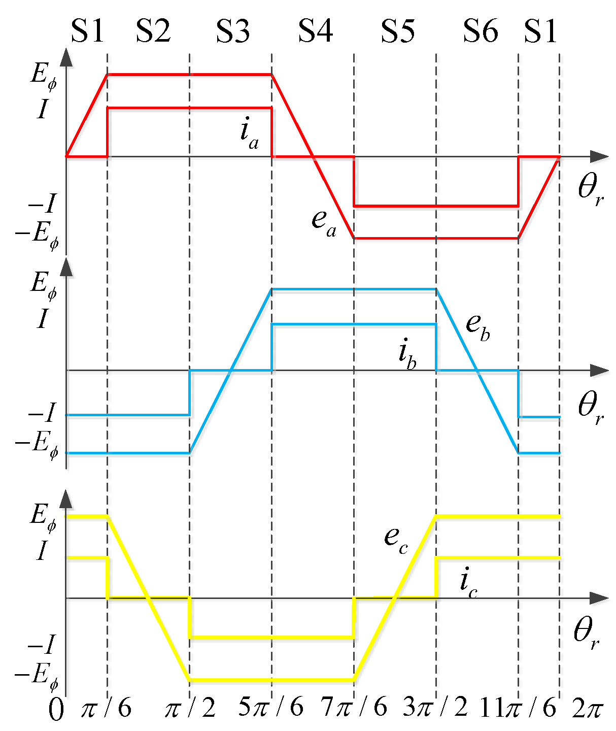
The per-unit values of the other 3 sectors can be calculated similarly. The waveforms of current and back-EMF are shown in Figure 2. Three phase currents are continuous without step changes.
4. Comparison of Commutation Torque Ripple
The commutation torque ripple of COC is analyzed and compared with traditional SWC in the stationary reference frame.
4.1. Square-Wave Control
When the rotor position is in the 4th sector, the phase current equations shown in Equation (4) are decomposed and considered as a vector in the stationary reference frame, then:
Assuming current vector , the modulus of is:
The angle of the current vector is . So, the angular velocity of the current vector is 0 in the 4th sector.
Back-EMF in the stationary reference frame is written as:
Assuming back-EMF vector , the modulus of back-EMF vector is:
When is in the middle of the 4th sector, is minimum. While, when is in the commutation region, is maximum:
The angle of back-EMF vector is:
can be expressed as:
The angular velocity of the back-EMF vector is:
When is in the middle of the 4th sector, is maximum. While, when is in the commutation region, is minimum:
The per-unit values value of torque can be expressed as:
When the rotor is in the 5th sector, the three-phase current equation shown in Equation (5) is decomposed in the stationary reference frame, then:
Its modulus is the same as Equation (18). The angle of the current vector is . The angular velocity of the current vector is 0 in the 5th sector. However, will be infinite in the commutation region for the step change of .
The similar study is carried out in the other sectors. The modulus, angular velocity and angle of current and back-EMF vector with SWC are shown in Figure 3, which are got according to the Equations (17)–(27). In the figure, the period of rotor electrical angle is set to 0.2 s, and the corresponding velocity of rotor is 31.4 rad/s.
In SWC, the properties of current and back-EMF vector are shown as follows.
- (1)
- The modulus of current vector is a constant.
- (2)
- The modulus of back-EMF vector is continuous and fluctuates with the angle of rotor. It is maximum in the commutation region, and minimum at the middle of sectors.
- (3)
- The velocity of current vector is 0 in sectors, and infinite in the commutation region.
- (4)
- The velocity of back-EMF vector is continuous and fluctuates with the angle of rotor. It is minimum in the commutation region, and maximum at the middle of sectors.
- (5)
- Current vector rotates asynchronously with back-EMF.
In the commutation region, the torque can be ripple-free if the modulus of current vector is constant and its velocity is infinite. However, the constant modulus and infinite velocity can hardly be satisfied for the limited current change rates restricted by the winding inductance, different current path, the voltage of the DC source and the speed of controller. So, few paper focus on how to keep the velocity of current vector infinite and the modulus constant to make the torque ripple free in the commutation region, because the actual current change rates cannot be infinite. And at present, most papers focus on keeping the change rates of currents equal to reduce commutation torque ripple. However, these methods cannot make the torque ripple free or minimum. So, a new driver method is necessary to solve the problems with SWC.
4.2. Current Optimizing Control
When the rotor position is in the 4th sector, the phase current equations shown in Equation (14) are decomposed in the stationary reference frame, then:
The modulus of the current vector is:
When is in the middle of the 4th sector, is maximum. When is in the commutation region, is minimum:
The angle of the current vector is the same as shown in Equation (22), and the velocity of the current vector is the same as shown in Equation (24).
The per-unit value of torque can be expressed as:
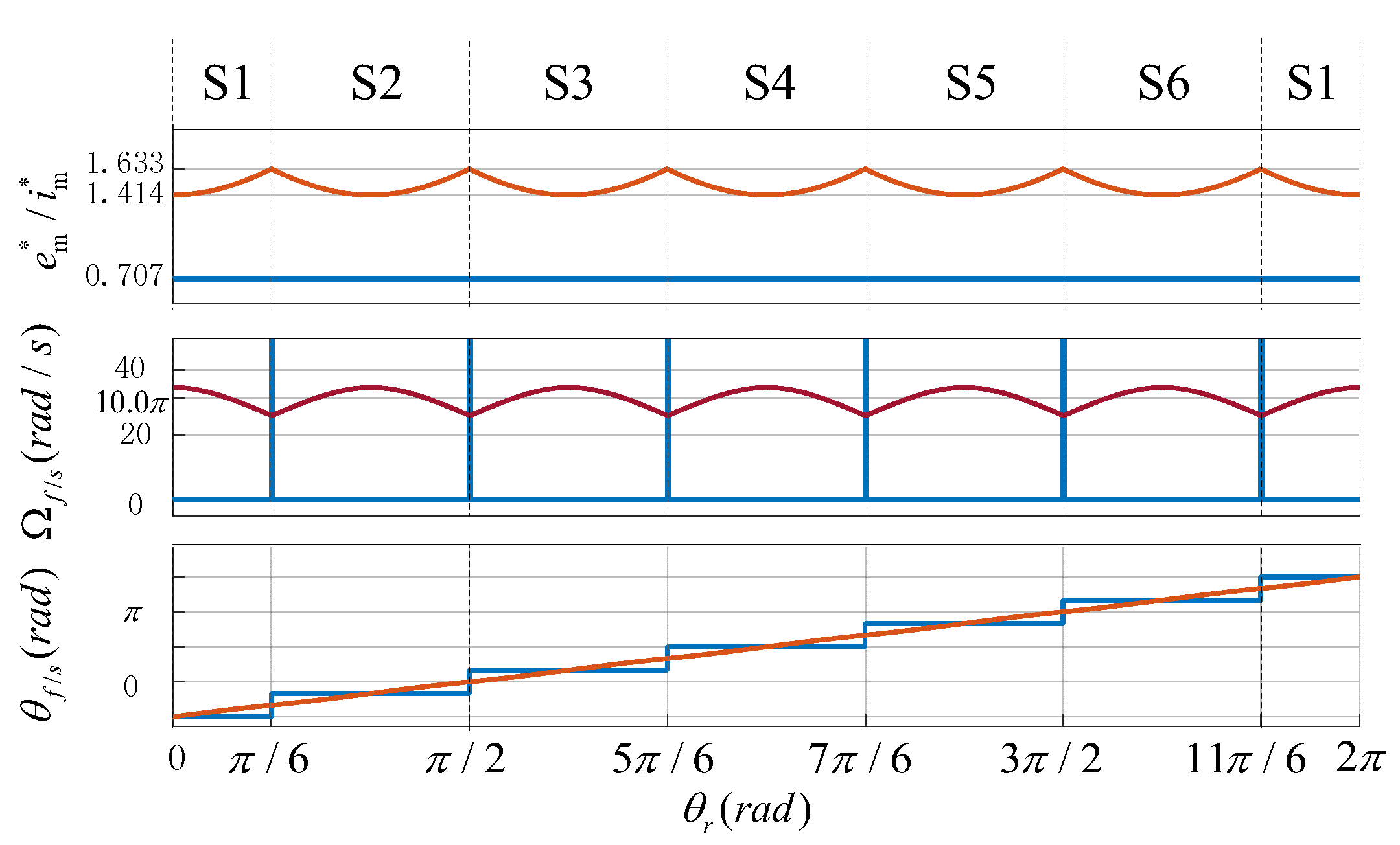
From Equations (20) and (29), the modulus of current and back-EMF vector is in inverse proportion. From Equations (22) and (24), the angle and velocity of current and back-EMF vector are synchronize. The velocity and modulus of current vector are minimum at the commutation time From Equations (25) and (30). From Equation (31), the dot product of current vector and back-EMF vector equals 1, and commutation torque is ripple-free. The modulus, angular velocity, and angle of current and back-EMF vector with COC are shown in Figure 4, which are got according to the Equations (28)–(31). In the figure, the period of rotor angle is also set to 0.2 s, the rotor angular velocity is 31.4 rad/s, the angular velocity and the angles of current vector and back-EMF vector are the same (blue cannot be displayed).
In COC, the properties of current and back-EMF vector are shown as follows:
- (1)
- The modulus of current vector is continuous and fluctuates with the angle of rotor. It is maximum at the middle of sectors, and minimum in the commutation region.
- (2)
- The velocity of current vector is continuous and fluctuates with the angle of rotor. It is maximum at the middle of sectors, and minimum in the commutation region.
- (3)
- Current vector rotates synchronously with back-EMF vector, the modulus of these vectors are in inverse proportion, and the angles and velocities are the same.
When the angle of rotor is in the commutation point of the 4th sector, the properties of current and back-EMF vector are shown in Table 1. Compared with SWC, the modulus of current vectors is decreased by 13.4%, and the velocity accounting for 82.7% of is limited in COC. The inner power factor angle is in SWC, while it is 0 in COC.
It can be seen that, the lowest modulus and limited velocity of current vector with COC in the commutation region reduce the demands of high current change rate. The contradiction between limited current change rate and the infinite velocity and higher modulus of current vector with SWC in the commutation region can be avoided. So, COC method has a natural advantage in terms of commutation torque ripple suppression.
5. Experiments
5.1. Experiment Setup
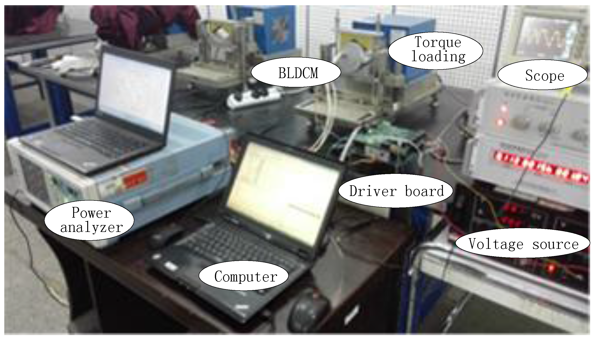
The experiment platform shown in Figure 5 is consisted of BLDCM, driver board, voltage source, computer, torque loading and power analyzer. The specifications of BLDCM are shown in Table 2.
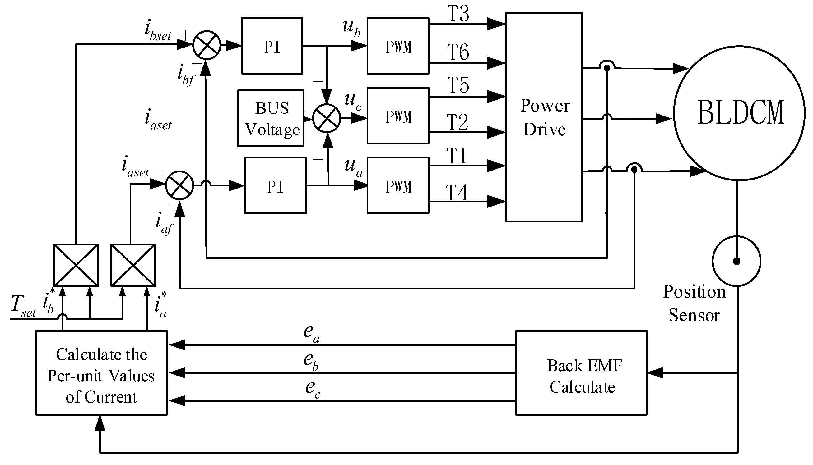
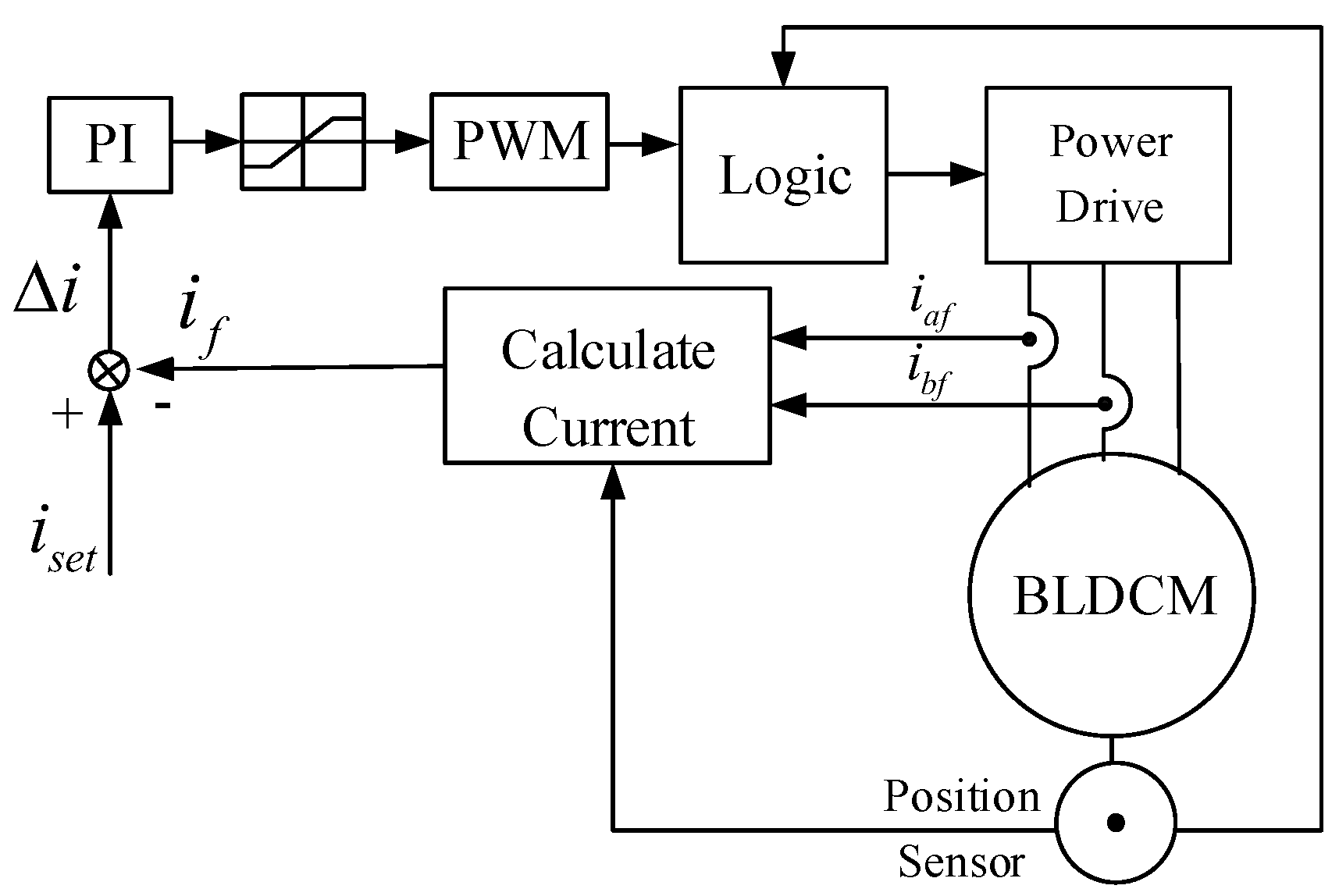
In the experiment, the voltage of DC source is kept constant, the reference speed is set by computer, and the load is regulated by torque loading. Torque is measured by sensor in torque loading. Current waveforms and torque are recorded by power analyzer. In driver board, double closed-loop (velocity loop outside, current loop inside) control strategy is adopted. Traditional PI control strategy is used in the velocity loop. COC and SWC method are adopted in the current loop. The control diagrams of COC and SWC are shown in Figure 6 and Figure 7 respectively.
In Figure 6, the per-unit values of three phase back-EMF are calculated by the rotor position. and are the per-unit values of given phase A and phase B currents, and they are calculated according to the back-EMF. Multiplying the given torque by and , the actual given current and can be calculated. is the output of velocity loop. Based on the PI regulator composed of the actual given and feedback currents, and is produced. can be derived from , and bus voltage. Six drive signals with dead band are produced by the PWM modular, and the signals drive the BLDCM through power current.
In Figure 7, the given current is the output of velocity loop, and is the feedback current calculated by the rotor position and two phase current. Based on the PI regulator composed of and , the given signal of PWM modular is produced. Six drive signals is produced by logic modular according to the PWM and rotor position. Power current is driven by the six drive signals.
5.2. Experiment Result
In the experiment, load torque and bus voltage are set to the rated values. Switching frequency is 20 kHz. The reference velocities are set to 1500 r/min and 3000 r/min respectively.
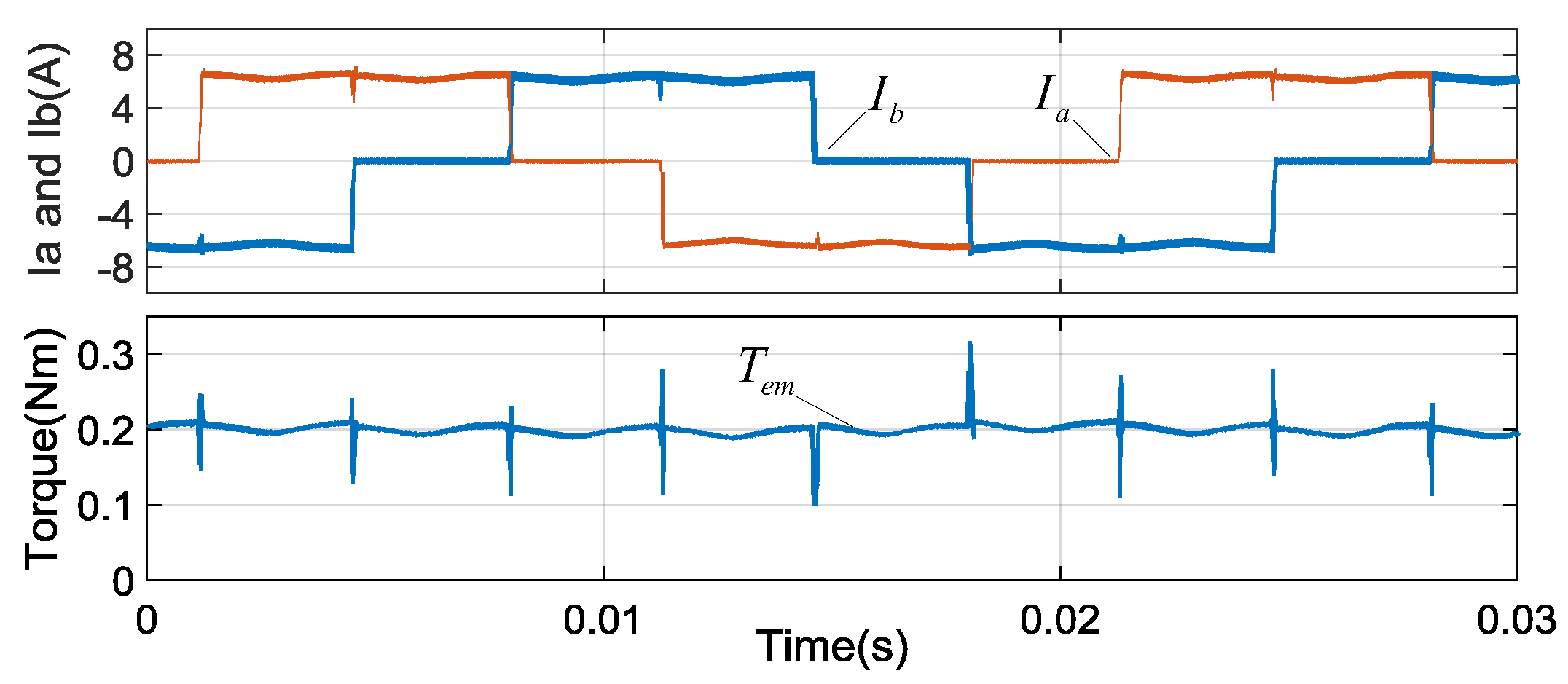
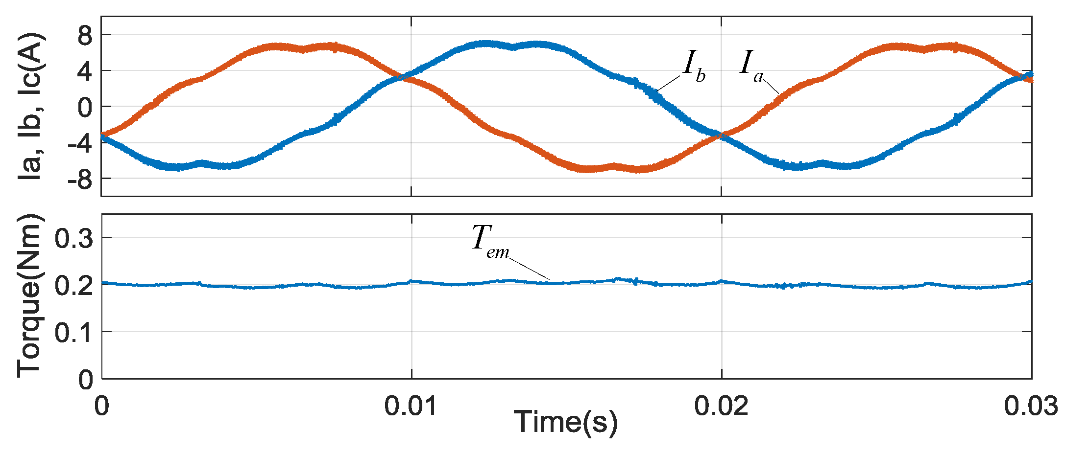
When the reference velocity is 1500 r/min, the test waveforms are shown in Figure 8 with SWC and Figure 9 with COC respectively.
In Figure 8, the phase currents are similar to square waves, and have two ripples during conduction region for the non-ideal trapezoidal back-EMF. However, the non-commutation current curves in during the commutation region. Commutation torque ripples 6 times every 20 ms.
In Figure 9, the phase currents are continuous and similar to that of Figure 2. In the commutation region, the phase current are smooth and commutation torque ripple is reduced. The torque ripple also concludes elements affected by the sampling errors of phase current and non-ideal trapezoidal back-EMF.
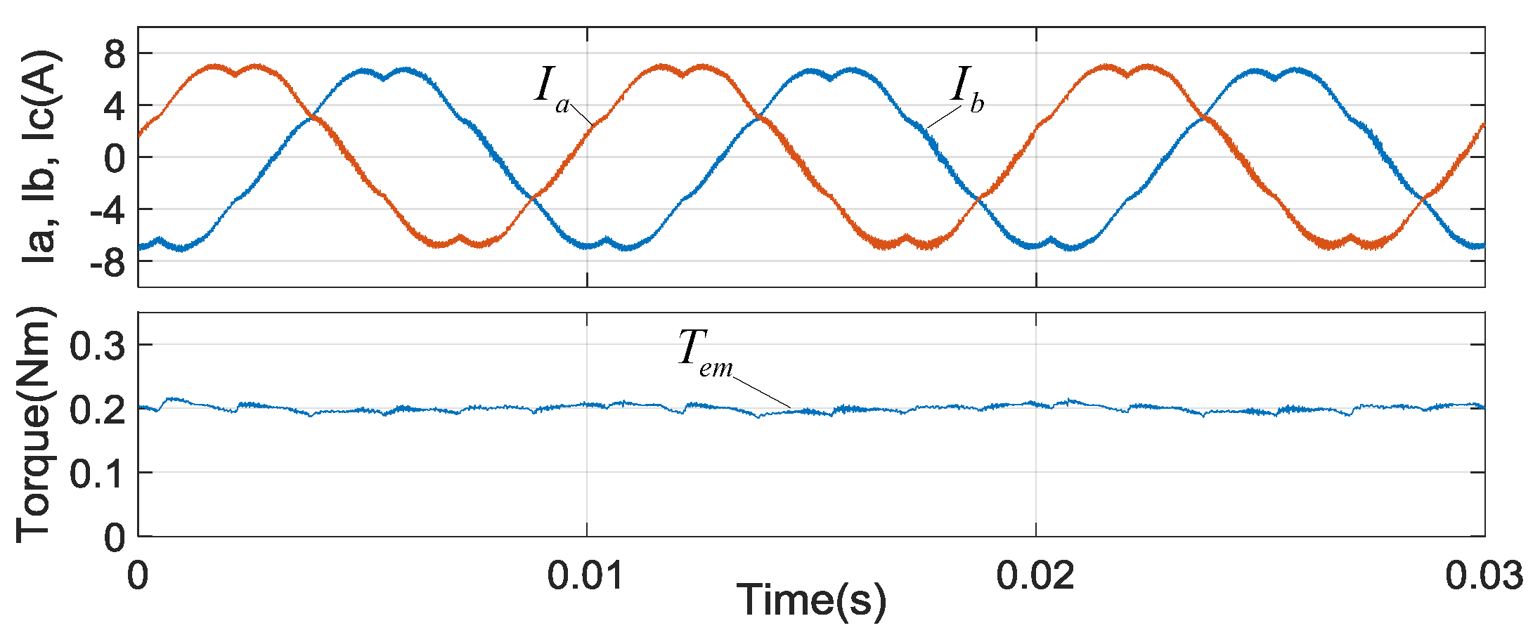
When the reference velocity is 3000 r/min, the test waveforms are shown in Figure 10 with SWC and Figure 11 with COC. In Figure 10, commutation torque ripple increases with the increasing of velocity. While in Figure 11, commutation torque ripple is still reduced.
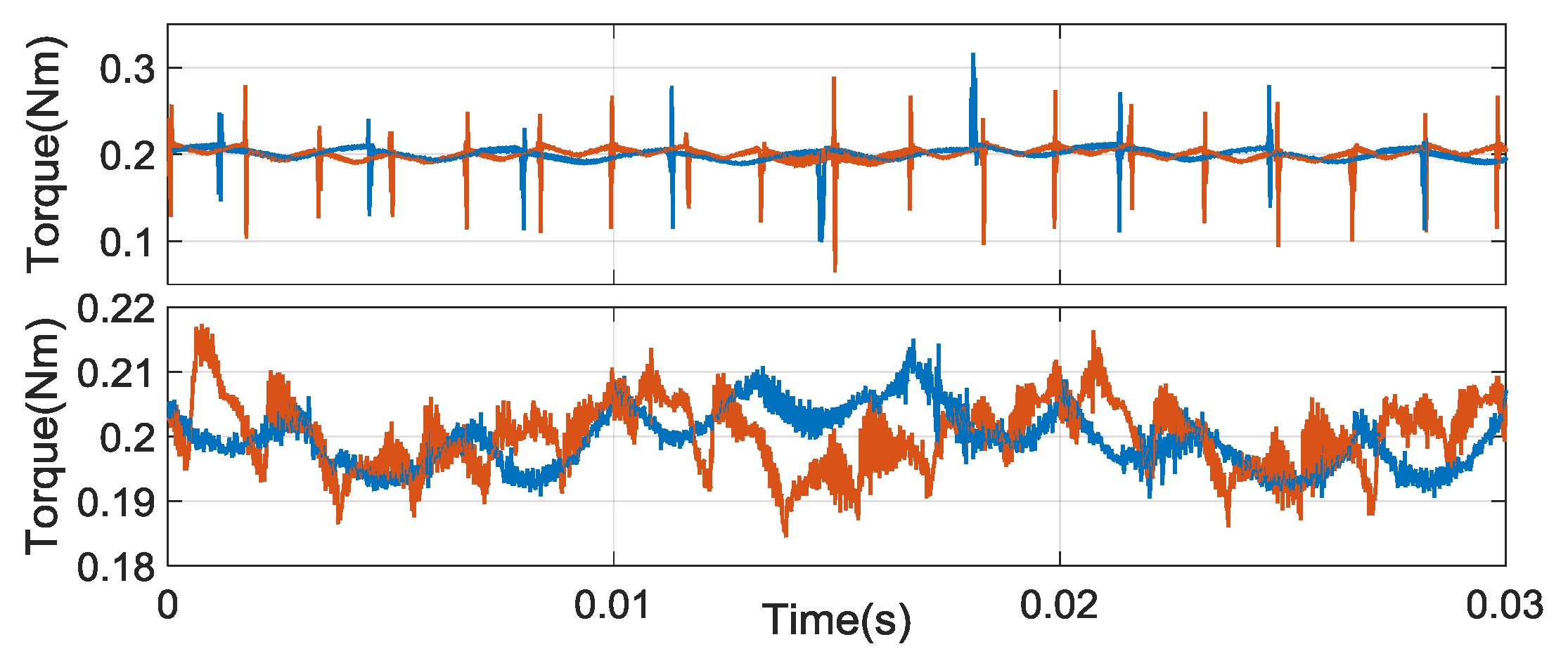
The waveforms of torque are enlarged in Figure 12. In SWC, torque ripples are affected by commutation events, PWM, the sampling errors and non-ideal trapezoidal back-EMF. The commutation torque ripple increasing with the rising of velocity is the main element. Other torque ripples having little relation to velocity are the minor. In COC, the ranges of torque ripples are mainly the same in both 1500 r/min and 3000 r/min. Commutation torque ripple is reduced. The results are shown in Table 3.
6. Conclusions
BLDCM has the disadvantage of the high commutation torque ripple, which limits its application in electric vehicles and servo systems. Analysis shows that the torque ripple is induced by the asynchrony of the current vector and the back-EMF vector in SWC. This is because the infinite velocity and constant modulus of the current vector is demanded in the commutation region by the asynchrony. However, the velocity is limited and the modulus is non-constant for the limited current change rates. A COC method in the natural a–b–c reference frame is proposed in the paper, which can keep the current vector and the back-EMF vector rotating synchronously. In COC, the modulus and velocity of the current vector demanded are minimum in the commutation region. The current change rates are reduced for the lowest modulus and the velocity of the current vector in the commutation region. The commutation torque ripple is minimum. Finally, the experimental results show that the COC method can reduce the commutation torque ripple in a wide speed range.
Acknowledgments
This work was supported in part by Shaanxi Key Research Project (2017GY-048).
Author Contributions
Bo Tan propose the COC method and designed the experiments; Lu Zhang and Bo Tan performed the experiments; Zhiguang Hua and Chun Fang analyzed the data and wrote the paper.
Conflicts of Interest
The authors declare no conflict of interest.
References
- Pillay, P.; Krishnan, R. Application characteristics of permanent magnet synchronous and brushless DC motors for servo drives. IEEE Trans. Ind. Appl. 1991, 27, 986–996. [Google Scholar] [CrossRef]
- Fang, J.C.; Zhou, X.X.; Liu, G. Precise Accelerated Torque Control for Small Inductance Brushless DC Motor. IEEE Trans. Power Electron. 2013, 28, 1400–1412. [Google Scholar] [CrossRef]
- Shi, J.; Li, T.C. New Method to Eliminate Commutation Torque Ripple of Brushless DC Motor With Minimum Commutation Time. IEEE Trans. Ind. Electron. 2013, 60, 2139–2146. [Google Scholar] [CrossRef]
- Xia, C.L.; Xiao, Y.W.; Chen, W.; Shi, T.N. Torque Ripple Reduction in Brushless DC Drives Based on Reference Current Optimization Using Integral Variable Structure Control. IEEE Trans. Ind. Electron. 2014, 61, 738–752. [Google Scholar] [CrossRef]
- Xia, C.L.; Wang, Y.F.; Shi, T.N. Implementation of Finite-State Model Predictive Control for Commutation Torque Ripple Minimization of Permanent-Magnet Brushless DC Motor. IEEE Trans. Ind. Electron. 2013, 60, 896–905. [Google Scholar] [CrossRef]
- Li, X.M.; Xia, C.L.; Cao, Y.F.; Chen, W.; Shi, T.N. Commutation Torque Ripple Reduction Strategy of Z-Source Inverter Fed Brushless DC Motor. IEEE Trans. Power Electron. 2016, 31, 7677–7690. [Google Scholar] [CrossRef]
- Xu, Y.X.; Wei, Y.Y.; Wang, B.C.; Zou, J.B. A Novel Inverter Topology for Brushless DC Motor Drive to Shorten Commutation Time. IEEE Trans. Ind. Electron. 2016, 63, 796–807. [Google Scholar] [CrossRef]
- Viswanathan, V.; Jeevananthan, S. Approach for torque ripple reduction for brushless DC motor based on three-level neutral-point-clamped inverter with DC-DC converter. IET Power Electron. 2015, 8, 47–55. [Google Scholar] [CrossRef]
- Li, Z.G.; Gao, X.F.; Wang, J.H.; Zhang, C.J. Phase back EMF space vector oriented control of brushless DC motor for torque ripple minimization. In Proceedings of the 2016 IEEE 8th International Power Electronics and Motion Control Conference, Hefei, China, 22–25 May 2016; pp. 2564–2570. [Google Scholar]
- Le-Huy, H.; Perret, R.; Feuillet, R. Minimization of Torque Ripple in Brushless DC Motor Drives. IEEE Trans. Ind. Appl. 1986, 748–755. [Google Scholar] [CrossRef]
- Bertoluzzo, M.; Buja, G.; Keshri, R.K.; Menis, R. Sinusoidal Versus Square-Wave Current Supply of PM Brushless DC Drives: A Convenience Analysis. IEEE Trans. Ind. Electron. 2015, 62, 7339–7349. [Google Scholar] [CrossRef]
- Park, S.J.; Park, H.W.; Lee, M.H.; Harashima, F. A new approach for minimum-torque-ripple maximum-efficiency control of BLDC motor. IEEE Trans. Ind. Electron. 2000, 47, 109–114. [Google Scholar] [CrossRef]
- Buja, G.; Bertoluzzo, M.; Keshri, R.K. Torque Ripple-Free Operation of PM BLDC Drives With Petal-Wave Current Supply. IEEE Trans. Ind. Electron. 2015, 62, 4034–4043. [Google Scholar] [CrossRef]
- Gatto, G.; Marongiu, I.; Perfetto, A.; Serpi, A. Brushless DC generator controlled by constrained predictive algorithm. In Proceedings of the 2010 IEEE International Symposium on Industrial Electronics, Bari, Italy, 4–7 July 2010; pp. 1224–1229. [Google Scholar]
- Damiano, A.; Deiana, F.; Fois, G.; Gatto, G.; Marongiu, I.; Serpi, A.; Perfetto, A. Performance comparison between two-phase-on and three-phase-on operation of Brushless DC drives. In Proceedings of the 2014 International Symposium on Power Electronics, Electrical Drives, Automation and Motion, Ischia, Italy, 18–20 June 2014; pp. 489–494. [Google Scholar]
- Serpi, A.; Fois, G.; Porru, M.; Damiano, A.; Marongiu, I. Space vector control of permanent Magnet Brushless DC Machines. In Proceedings of the 2016 XXII International Conference on Electrical Machines, Lausanne, Switzerland, 4–7 September 2016; pp. 1194–1200. [Google Scholar]
Figure 1.
Ideal waveforms of back-EMF and phase current in square-wave current control (SWC).

Figure 2.
The waveforms of current and back-EMF.

Figure 3.
The waveforms of vector modulus, angular velocity, and angle with square-wave current control (SWC): (up) modulus of current vector (blue) and back-EMF (red); (middle) angular velocity of current vector (blue) and back-EMF vector (red); (down) angles of current vector (blue) and back-EMF vector (red).

Figure 4.
The waveforms of vector modulus, angular velocity, and angle with current optimizing control (COC): (up) modulus of current vector (blue) and back-EMF (red); (middle) angular velocity of current vector (blue) and back-EMF vector (red); (down) angles of current vector (blue) and back-EMF vector (red).

Figure 5.
The experiment platform.

Figure 6.
Control diagram of COC.

Figure 7.
Control diagram of square-wave current control (SWC).

Figure 8.
Test waveforms at the speed of 1500 r/min with SWC.

Figure 9.
Test waveforms at the speed of 1500 r/min with COC.

Figure 10.
Test waveforms at the speed of 3000 r/min with SWC.

Figure 11.
Test waveforms at the speed of 3000 r/min with COC.

Figure 12.
Test waveforms of torque: (up) with SWC (red line: 3000 r/min; blue line: 1500 r/min); (down) with COC (red line: 3000 r/min; blue line: 1500 r/min).
Figure 12.
Test waveforms of torque: (up) with SWC (red line: 3000 r/min; blue line: 1500 r/min); (down) with COC (red line: 3000 r/min; blue line: 1500 r/min).


Table 1.
The properties of current vector and back-EMF when .
| Type | Modulus | Velocity | Angle |
|---|---|---|---|
| Current vector of SWC | |||
| Current vector of COC | |||
| Back-EMF vector |
Table 2.
Specifications of the brushless DC motor (BLDCM).
| Specification | Value |
|---|---|
| Rated voltage | 24 V |
| Rated torque | 0.2 Nm |
| Rated Velocity | 3950 r/min |
| Rated current | 5 A |
| Rated power | 82 W |
| Torque coefficient | 0.0475 Nm/A |
| Resistance of phase | 0.49 Ω |
| Inductance of phase | 0.16 mH |
| Numbers of pole pairs | 2 |
Table 3.
Torque ripple comparison of SWC and COC.
| Type | Velocity (r/min) | Commutation Ripple (Nm) | Other Ripple (Nm) |
|---|---|---|---|
| SWC | 1500 | 0.115 | 0.008 |
| COC | 1500 | 0.014 | 0.008 |
| SWC | 3000 | 0.135 | 0.008 |
| COC | 3000 | 0.016 | 0.009 |
© 2017 by the authors. Licensee MDPI, Basel, Switzerland. This article is an open access article distributed under the terms and conditions of the Creative Commons Attribution (CC BY) license (http://creativecommons.org/licenses/by/4.0/).
Share and Cite
MDPI and ACS Style
Tan, B.; Hua, Z.; Zhang, L.; Fang, C. A New Approach of Minimizing Commutation Torque Ripple for BLDCM. Energies 2017, 10, 1735. https://doi.org/10.3390/en10111735
AMA Style
Tan B, Hua Z, Zhang L, Fang C. A New Approach of Minimizing Commutation Torque Ripple for BLDCM. Energies. 2017; 10(11):1735. https://doi.org/10.3390/en10111735
Chicago/Turabian StyleTan, Bo, Zhiguang Hua, Lu Zhang, and Chun Fang. 2017. "A New Approach of Minimizing Commutation Torque Ripple for BLDCM" Energies 10, no. 11: 1735. https://doi.org/10.3390/en10111735
Note that from the first issue of 2016, this journal uses article numbers instead of page numbers. See further details here.