Design and Development of MIMO Antennas for WiGig Terminals
by
 , , and
Sultan Shoaib
1 ,
,
Nosherwan Shoaib
2,*,
Riqza Y. Y. Khattak
3,
Imran Shoaib
4,
Masood Ur Rehman
5 and
Xiaodong Yang
6 1
School of Applied Science, Computing and Engineering, Wrexham Glyndwr University (WGU), Mold Road, Wrexham, Wales LL11 2AW, UK
2
Research Institute for Microwave and Millimeter-Wave Studies (RIMMS), National University of Sciences and Technology (NUST), Islamabad 44000, Pakistan
3
Department of Electrical Engineering, HITEC University, Taxila 47080, Pakistan
4
School of Electronic Engineering and Computer Science, Queen Mary University of London, 327 Mile End Road, London E1 4NS, UK
5
James Watt School of Engineering, University of Glasgow, Glasgow G12 8QQ, UK
6
School of Electronic Engineering, Xidian University, Xi’an 710071, China
*
Author to whom correspondence should be addressed.
Electronics 2019, 8(12), 1548; https://doi.org/10.3390/electronics8121548
Submission received: 31 October 2019
/
Revised: 28 November 2019
/
Accepted: 3 December 2019
/
Published: 16 December 2019
(This article belongs to the Section Microwave and Wireless Communications)
Abstract
:This article presents a design for high-gain MIMO antennas with compact geometry. The proposed design is composed of four antennas in MIMO configuration, wherein, each antenna is made up of small units of microstrip patches. The overall geometry is printed on the top layer of the substrate, i.e., Rogers RT-5880 with permittivity of 2.2, permeability of 1.0, dielectric loss of 0.0009, and depth of 0.508 mm. The proposed design covers an area of 29.5 × 61.4 mm2, wherein each antenna covers an area of 11.82 × 25.28 mm2. The dimensions of the microstrip lines in each MIMO element were optimized to achieve a good impedance matching. The design is resonating at 61 GHz, with a wide practical bandwidth of more than 7 GHz, thereby covering IEEE 802.11ad WiGig (58–65 GHz). The average value of gain ranges from 9.45 to 13.6 dBi over the entire frequency bandwidth whereas, the average value of efficiency ranges from 55.5% to 84.3%. The proposed design attains a compact volume, wide bandwidth, and good gain and efficiency performances, which makes it suitable for WiGig terminals.
1. Introduction
Nowadays, there is an increasing demand for high data rates, high voice quality, and video applications around the world. Data rates of 3G and 4G technology do not satisfy the future data-rate requirements. Wireless Gigabit Alliance (WiGig) is an emerging technology that will play a vital role in providing higher data rates for industrial and communication sectors. It has its own standardized protocol that is IEEE 802.11ad (58–65 GHz). The high operating frequency of WiGig will meet the future requirements of higher data rates to transfer data, voice, and video streaming at multigigabits per seconds. It is therefore a mandatory requirement to design and build advanced antennas to support an ultra-high data rate. Antenna designing at millimeter (mm)-wave frequencies is currently a highly demanded area of research around the world. In addition, the fabrication of these antennas is very challenging, since the antenna dimensions are very small.
Several designs of antennas for mm-wave frequencies have been presented in [1,2,3,4,5,6,7,8,9,10,11,12,13,14,15,16,17,18,19,20,21,22,23,24,25,26,27,28]. In [1], a low-temperature co-fired ceramic (LTCC) material is used for low-cost, wide bandwidth and high performance of the magnetoelectric dipole antenna. The design presented incorporates plated through-hole technology and waveguide feed for achieving high gain and excitation of higher-order modes. Another design is shown in [2] in which authors presented that for antenna designing at 60 GHz, Sukhoi Su-8 substrate (ɛ = 3.1, tangent loss = 0.021) with coplanar feed is a better option. One such reconfigurable patch antenna with co-planar feed, using Su-8 substrate, is presented in [3]. The design being narrow band partially covers IEEE 802.11ad WiGig with a gain of 7 dB at 62 GHz. In order to expand the bandwidth, a higher order EM mode patch antenna is presented in [4]. The author presented the techniques of using slots and multiple antennas to increase the gain. Another design with enhanced bandwidth is presented in [5]. In this design, a magnetoelectric dipole antenna array is proposed which provides multibeam end fire radiation at 60 GHz. It is an horizontally polarized antenna fed by substrate integrated waveguide and multilayer zigzag topology for beam forming. The proposed design is compact and possesses a good percentage of bandwidth, however, the peak efficiency achieved is not better than 65%, which primarily occurred due to poor return loss performance of the antenna. In order to improve the return loss, a stacked planar antenna, using Rogers RT-5880 substrate, is presented in [6]. The design resonates at 60.1 GHz with a bandwidth ranging from 59.5 to 60.5 GHz. The peak gain achieved for the design is 7.5 dBi, which makes it unsuitable for WiGig high-data-rate terminals. In order to achieve a high gain and efficiency, while covering a wide bandwidth, array antennas can be used. One such design is presented in [7]. An array of dipole antenna is proposed that is stuffed with substrate integrated H-plain cut of a horn antenna. It is designed for broadband and multiband wireless applications. The bandwidth achieved for the proposed design is greater than 13 GHz, with a gain ranging from 9 to 12 dBi. A design presented in [8] shows a bowtie antenna that uses 4 × 4 arrays for achieving a multibeam radiation pattern in the E-plane. The design comprises magnetic resonators, implemented using double-sided split-ring unit cells (DSRRs). Its bandwidth ranges from 56 to 66 GHz, and the peak value of the gain is 11.4 dBi at 62 GHz.
With an increasing trend toward miniaturization, the sizes of the components in the antenna industry are reducing day by day. In [9], the author presented an antenna with reduced size. The design incorporates the approach of system-in-packaging in which a high-temperature co-fired ceramics (HTCC) substrate is used to achieve gain value of 7.8 dBi at 60 GHz. Similarly, in [10], a small printed antenna that is the size of a shirt button is presented for 60 GHz frequency. The design is unique and can be attached to garments, etc. The bandwidth achieved by the design is 56–65 GHz bandwidth with peak realized gain of 4 dBi, which is quite low for high-data-rate applications. In [11], a magnetoelectric dipole antenna was designed at the WiGig frequency that gives maximum radiation at theta 0° direction. It is horizontally polarized and fed by the open-ended substrate integrated waveguide (SIW). Every couple of electric dipoles consists of four patches, which provide high impedance bandwidth and 11.7 dBi peak gain. By increasing the number of pairs of SIW and using multilayers zigzag topology, the size of end-fire dipole can be reduced further. Another compact design is presented in [12], which shows a single-patch dual-band antenna at 60 GHz frequency. It is designed on two higher modes, to operate it as a dual-band antenna at 59 and 63.5 GHz, and the gain values achieved at these frequencies are 9.3 and 10.1 dBi, respectively. Another design of dual-band antenna is presented in [13]. The design proposed operates on both Wi-Fi and WiGig channels. In the Wi-Fi mode, the antenna operates as a printed monopole, whereas, at 60 GHz, it operates as a patch antenna that is shorted to operate at a higher mode. It is designed on single-layer printed circuit board, and through-plated holes are used to achieve its multiband characteristics. Also, it includes a low pass filter to feed the monopole antenna and to isolate it from the patch. Though the proposed design is dual-band, the fabrication of the design is complex, along with small gain performance of 5–6 dBi at mm-wave frequency. In [14], a distinctive methodology was adopted to design a two-beam radiator at 57–64 GHz bandwidth. The design presented is a gap waveguide-based antenna with slots. The peak gain achieved by this approach is 10 dBi with an efficiency of 91.4% at WiGig frequency.
The true benefits of WiGig technology can be exploited by incorporating modern techniques of antenna designing predominantly multiple input multiple output (MIMO). MIMO technology promises an increased range, an enhanced data throughput, and a better capacity performance, without consuming additional power and frequency bandwidth. One such antenna is shown in [15], wherein a switched beam 2 × 2 MIMO antenna is presented, along with a detailed analysis of the MIMO performance. The results presented by the author show that the design provides a high data rate, a better capacity performance, and a high gain compared to the single-element antennas. Another design of MIMO antenna is presented in [16], wherein a printed MIMO antenna with a defected ground plane is designed at 60 GHz. It is a folded L-shaped patch antenna made on Si-wafer. The design presented by the author possesses poor efficiency and gain performances, thus making it unsuitable for WiGig terminals. Similarly, a design with poor gain performance is presented in [17]. The design comprises a dual polarized mobile antenna at 60 GHz, with vertical polarized directivity of 3.8 dBi and horizontal polarized directivity of 4.5 dBi. In addition, the design possesses poor isolation in MIMO configuration. In MIMO, mutual coupling between multiple antenna elements is a key problem and is a potential area under research. Different techniques have been proposed in the literature by authors across the globe. One such technique is presented in [18] in which a meta-material polarization rotator (MPR) wall is used to improve the decoupling between the two dielectric resonator antennas (DRAs). The isolation achieved at 60 GHz is 22 dB. The proposed design, however, is composed of metamaterials and dielectric resonators, which are quite costly, making it not suitable for future portable terminals. Another methodology for improving the decoupling performance of MIMO antennas is presented in [19]; it uses a meta-surface shield for the improvement of decoupling. The shield presented is made up of multiple split-ring resonator (SRR) cells that are combined in the form of an array. The isolation achieved is approximately 43 dB, with a gain of 7.9 dBi and efficiency of 91%. Most of the designs presented from the literature are of single antennas, whereas few designs of MIMO antennas are presented. The antennas that are discussed above have major issues, such as narrow bandwidth, poor gain and efficiency, high cost, and complex fabrication. It is therefore a necessary requirement to design advanced MIMO and array antennas for achieving a high gain over a wide bandwidth with acceptable isolation performance.
In this paper, a novel design for high-gain MIMO antennas with compact geometry is presented for WiGig frequency. The proposed design is composed of four antennas in MIMO configuration, wherein each antenna comprises small microstrip patches. The novelty of the proposed design lies in its capability of being MIMO, high-gain, and wideband at the same time, a combined feature missing in the designs discussed earlier. The proposed design is thus suitable for the applications which require large throughput and increased channel capacity, simultaneously. The antenna design, along with the parametric analysis and the simulation and the measurement results, is presented in the next sections.
2. Antenna Modelling
2.1. Antenna Design
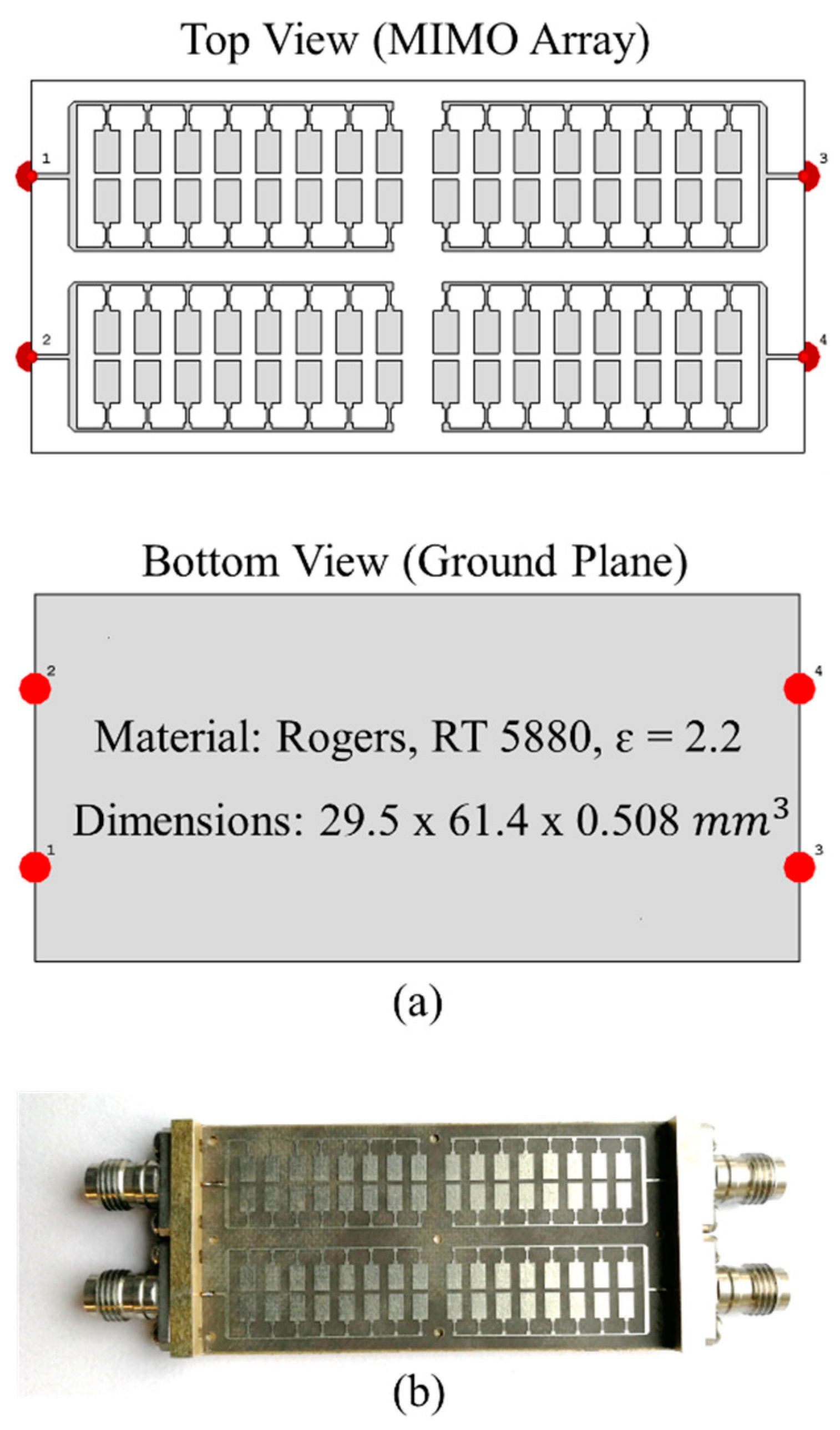
The simulated and fabricated prototype of the MIMO antennas for WiGig terminals is shown in Figure 1. The antennas were designed and simulated in CST Microwave Studio® [29]. Each antenna of the MIMO configuration is composed of 16 microstrip patches, which are fed simultaneously by using microstrip lines. The length of each patch element is 3.40 mm, and that is approximately 0.68 λ at 60 GHz. The substrate material used for the design is Rogers RT-5880 with permittivity of 2.2, permeability of 1.0, dielectric loss of 0.0009, and depth of 0.508 mm. The proposed design is compact and covers an area of 29.5 × 61.4 mm2, wherein each antenna covers 11.82 × 25.28 mm2. The design is prototyped in the antenna laboratory at Xidian University, China, and the connectors used for the input ports are 1.85 mm end launch connectors, with the main pins soldered to the design, whereas the connectors are adjusted with the housing by means of the screws.
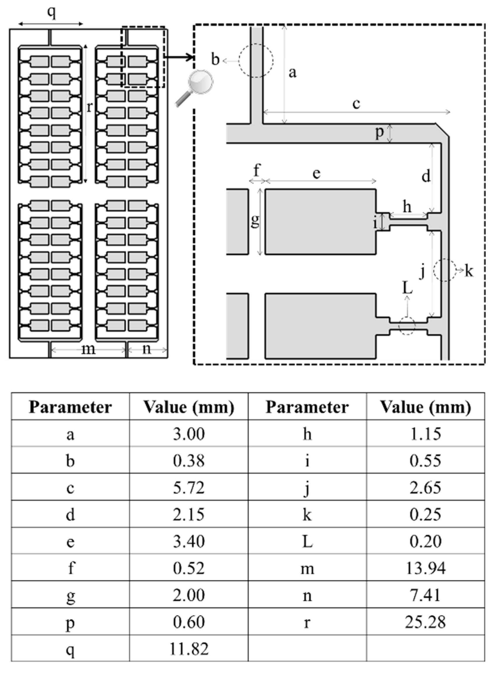
The detailed dimensions of the antenna design are shown in Figure 2. It can be seen that the design comprises numerous electrically small elements whose dimensions were optimized through extensive simulation work. Each parameter is tuned through repeated optimization in CST Microwave Studio for achieving a good impedance matching and an excellent radiation performance. Also, the position and spacing between the MIMO elements were carefully tuned, to achieve optimum decoupling, while retaining a wide bandwidth. A parametric analysis of some of the key dimensions is presented in the next section.
2.2. Parametric Analysis
A comprehensive analysis on various parameters of the antenna design was carried out to visualize the effect on the performance of the MIMO antennas. This section presents the effect of each parameter.
2.2.1. Stepwise Design
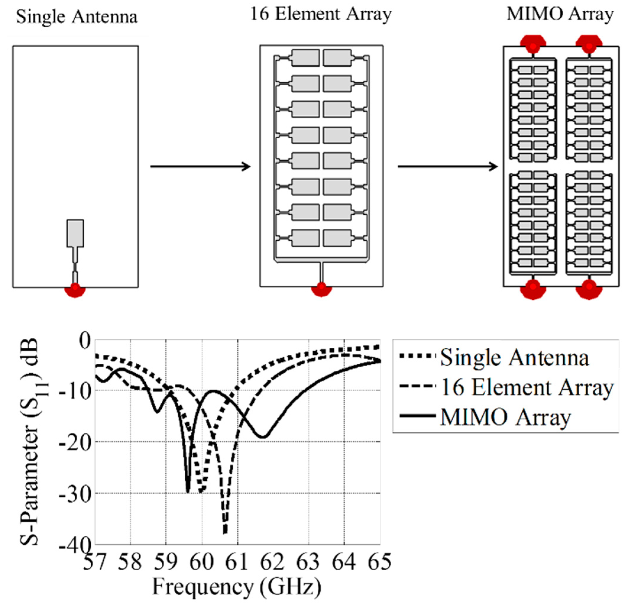
The design presented in this work can be dissected into three distinct configurations. Configuration 1 is composed of a simple patch antenna printed on the substrate with optimized dimensions of the antenna and the feed line. Configuration 2 is composed of a single antenna of the MIMO Configuration, whereas, Configuration 3 is the proposed MIMO design. The S-parameters (S11) of each configuration are shown in Figure 3. It can be seen that the MIMO configuration gives a wider frequency −6 dB/−10 dB bandwidth as compared to the other two configurations. Also, extensive simulation work has shown that the positioning and alignment of 16 patch elements in each antenna gives better current distribution, gain, and efficiency as compared to if the elements were aligned in any other configuration.
2.2.2. Parameter ‘b’
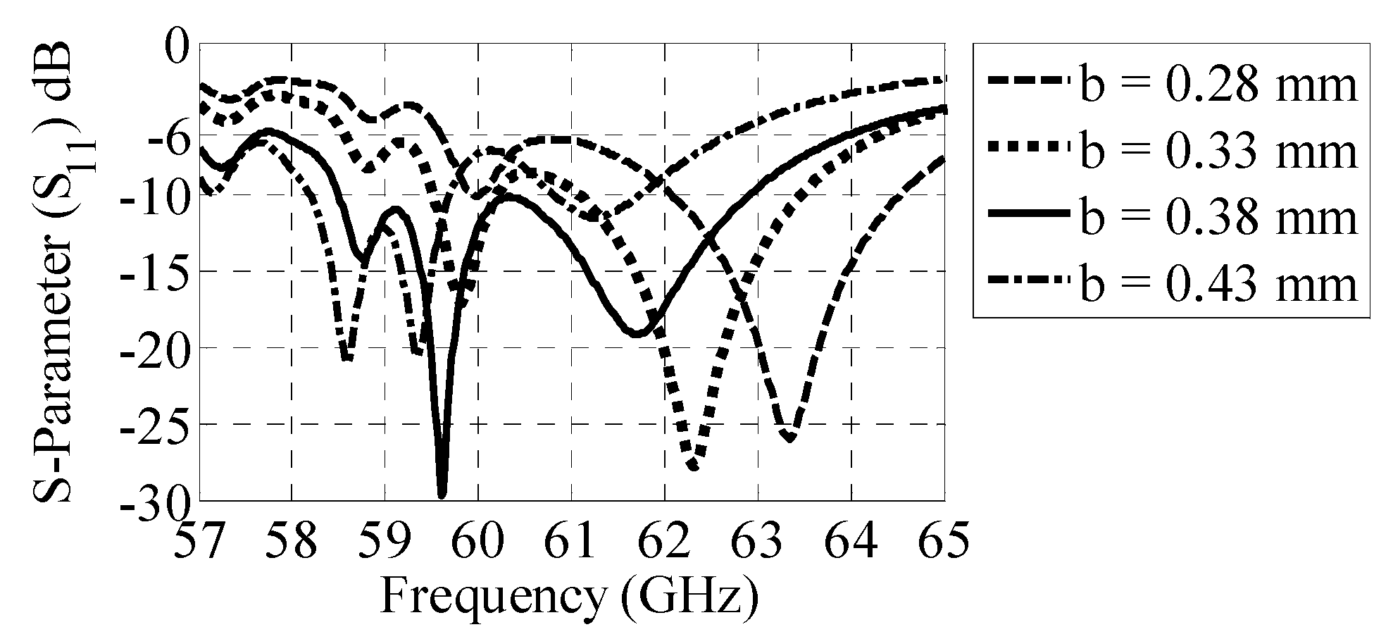
Parameter ‘b’, as shown in Figure 2, presents the width of the main feed line of each MIMO element. The value of parameter ‘b’ is varied from 0.28 to 0.43 mm, and the S-parameters (S11) at different values are shown in Figure 4. It can be seen that the parameter value of 0.38 mm gives a wider frequency bandwidth as compared to the other values.
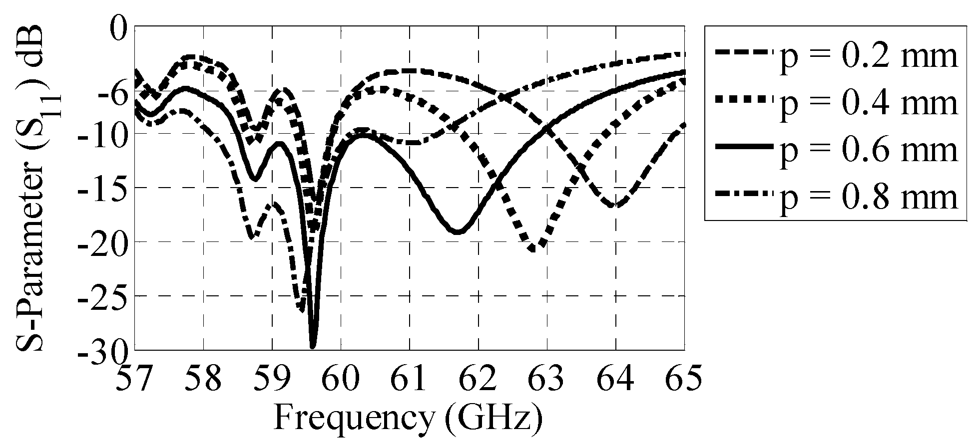
2.2.3. Parameter ‘p’
Parameter ‘p’, as shown in Figure 2, presents another width of the feed line in each MIMO element. The value of parameter ‘p’ is varied from 0.2 to 0.8 mm, and the S-parameters (S11) at different values are shown in Figure 5.
It can be seen that the parameter value of 0.6 mm gives a wider frequency bandwidth as compared to the other values. Moreover, as the value of parameter ‘p’ increases from 0.2 mm to 0.8 mm, the resonant frequency shifts from 64 to 59 GHz.
2.2.4. Parameter ‘k’
Parameter ‘k’, as shown in Figure 2, presents the width of the feed line feeding 16 microstrip patches in each MIMO element. The value of parameter ‘k’ is varied from 0.15 to 0.3 mm, and the S-parameters (S11) at different values are shown in Figure 6. It can be seen that the parameter value of 0.25 mm gives a better return-loss performance as compared to the other values.
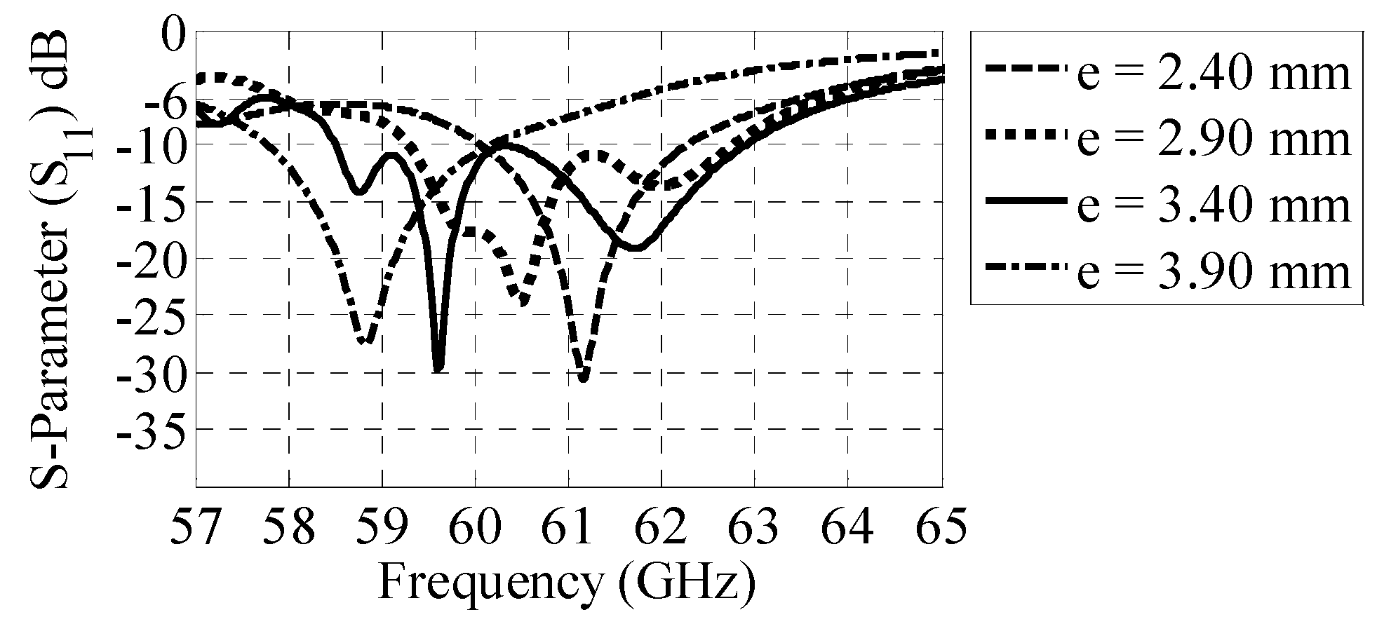
2.2.5. Parameter ‘e’
Parameter ‘e’, as shown in Figure 2, presents the length of the microstrip patch that, in combination with 15 other identical elements, makes up the individual antenna of the MIMO configuration. The value of parameter ‘e’ is varied from 2.40 to 3.90 mm, and the S-parameters (S11) at different values are shown in Figure 7. It can be seen that the parameter value of 3.40 mm gives a better return-loss performance and frequency bandwidth as compared to the other values. Moreover, as the value of parameter ‘e’ increases, the resonant frequency decreases, and vice versa.
3. Results and Discussions
This section presents the simulation and measurement results of the proposed MIMO antennas for WiGig terminals.
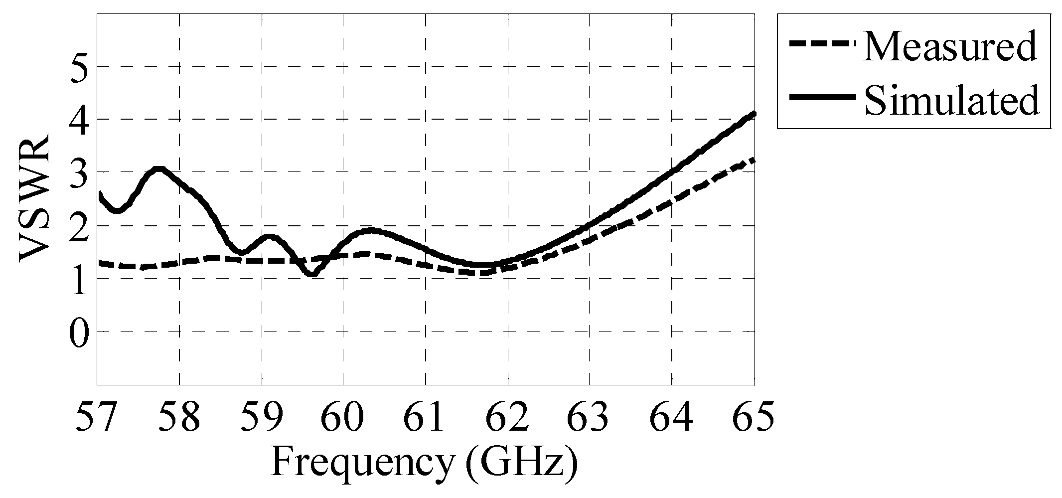
3.1. Reflection Coefficient (VSWR)
The VSWR curves for the MIMO antennas are shown in Figure 8.
The proposed antennas attain a simulated bandwidth of 6.14 GHz, which is approximately 10.3% and ranges from 57.9 to 64 GHz when referenced to a VSWR ratio of 3:1, whereas the practical bandwidth achieved is greater than 7 GHz, which ranges from <57 to 64.7 GHz, when referenced to a VSWR ratio of 3:1. The design possesses a wide bandwidth and almost completely covers the IEEE 802.11ad WiGig frequency band, which ranges from 58 to 65 GHz [30].
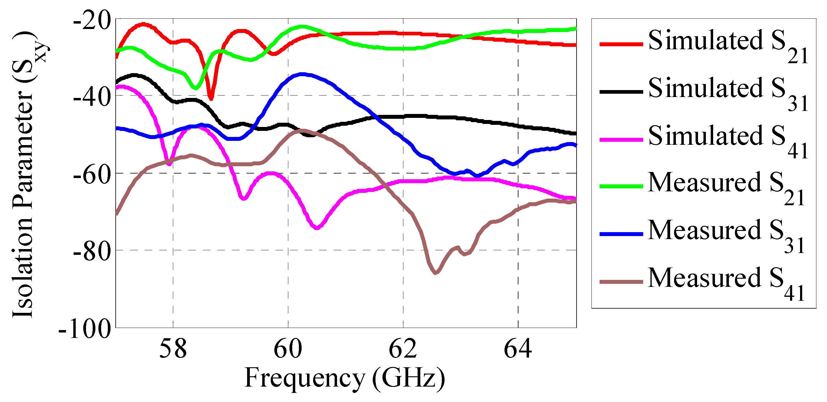
3.2. Isolation (SXY)
The SXY curves of the MIMO antennas are shown in Figure 9. It can be seen that the antennas in MIMO configuration possess excellent isolation performance. The average measure isolation at 60 GHz is approximately –36 dB. The simulated and measured isolation between port 1 and port 2 is less than the isolation between other port pairs, such as port 1 and port 3 or port 1 and port 4. This is because the coupling of the surface current between port 1 and port 2 is comparatively large due to a close separation distance compared to that of the other port pairs.
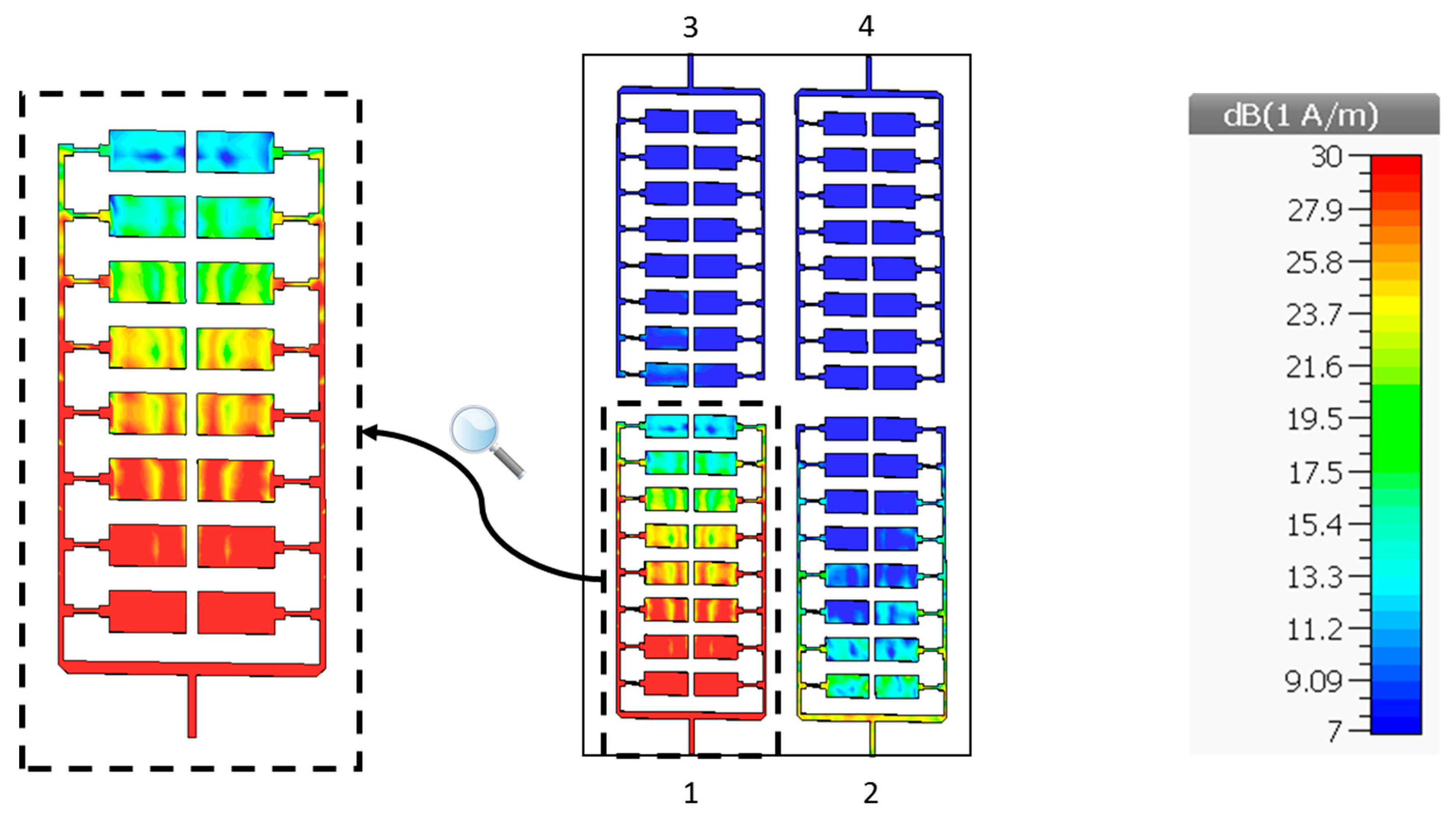
3.3. Current Distribution
Each element of the MIMO configuration is composed of 16 patch elements and the microstrip lines feeding the patch elements. The feeding lines were carefully modelled to maximize the distribution of the current, as presented in Figure 10.
The distribution of the surface current is presented at 60 GHz. It can be seen that the feeding lines distribute the current such that individual patch elements get a good share of the current, which means that the 16 patch elements contribute toward the radiation of the antenna. However, the current is more concentrated in the first four rows than the final four rows, which means that the first four rows contribute toward the radiation of antenna more than the final four rows, thus making the radiation directional. However, it can be anticipated that the radiation would be more directional with narrower beamwidth if all rows had received an equal concentration of surface current. It can also be seen that a high isolation is achieved between MIMO elements, as the amount of coupling current is minor in comparison to the maximum current.
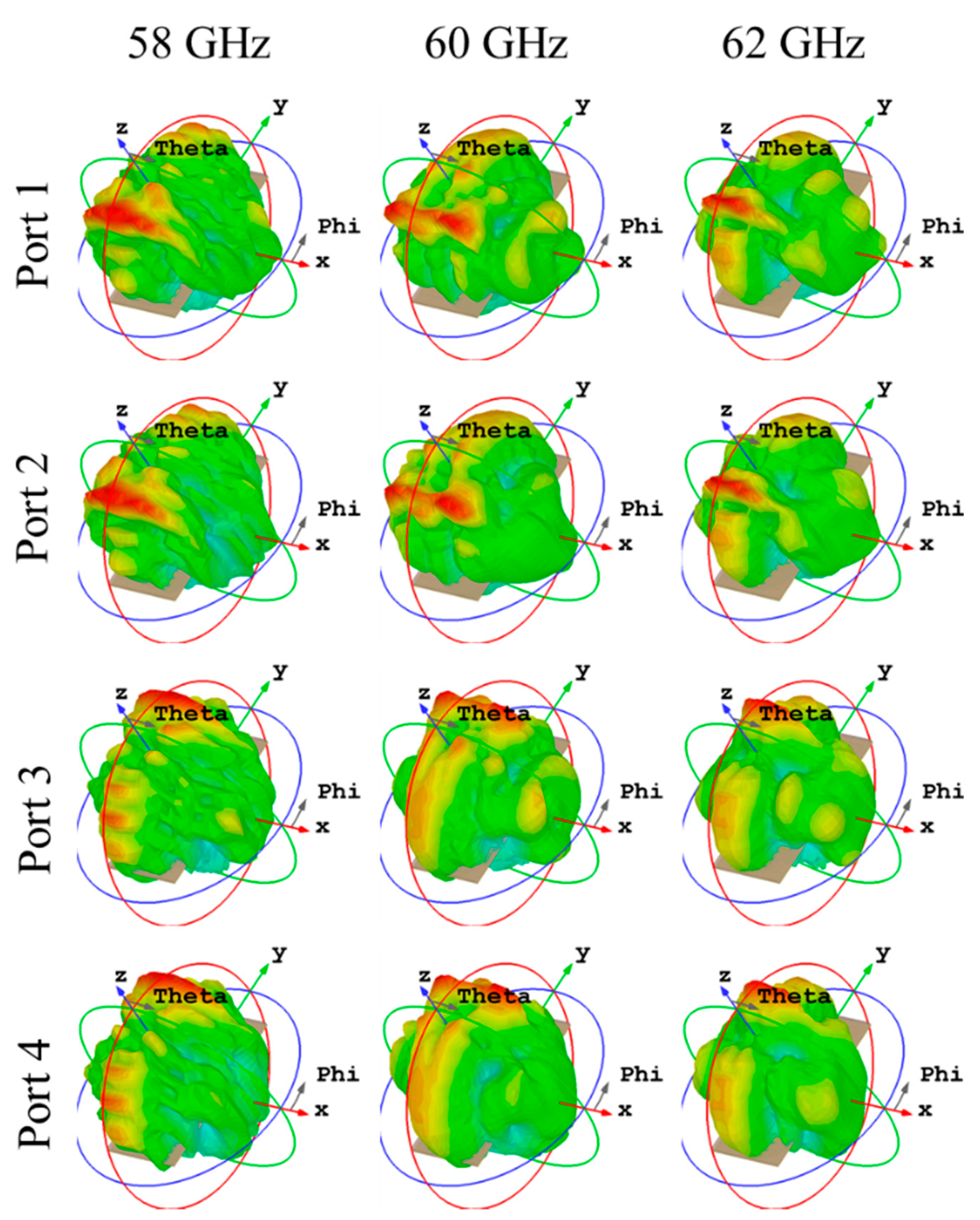
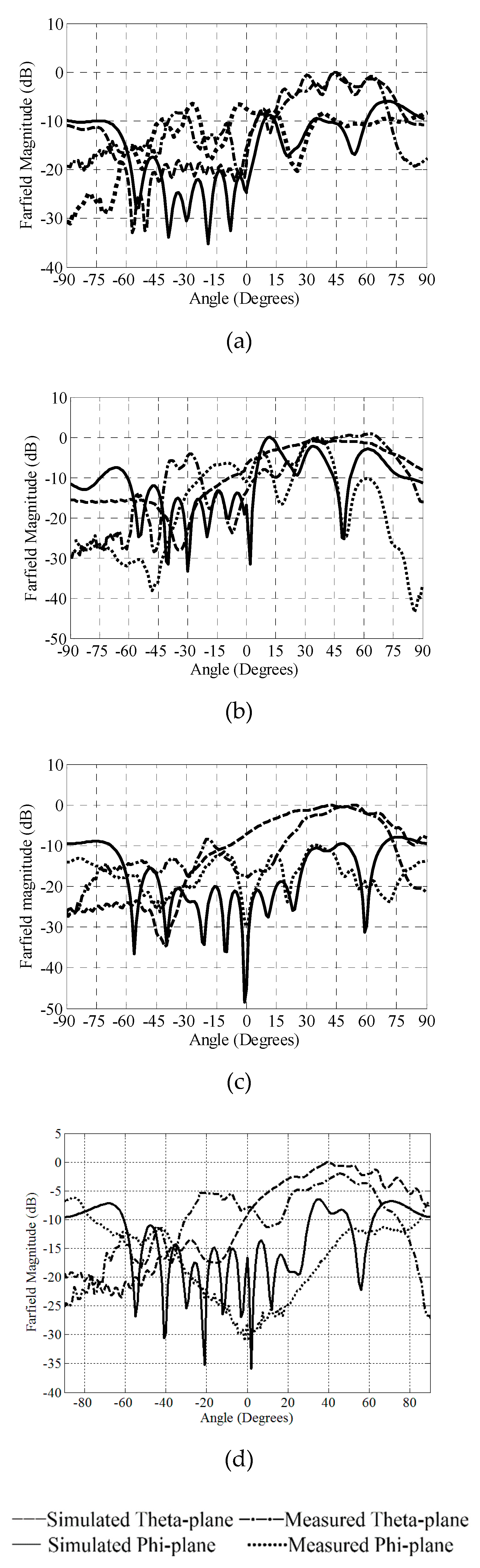
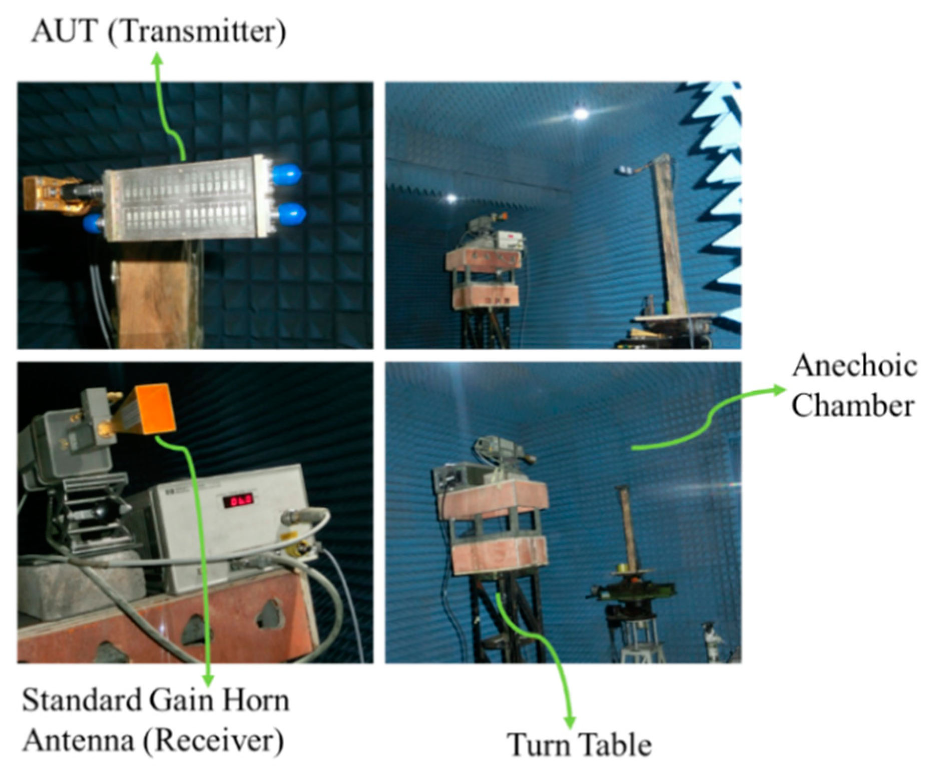
3.4. Radiation Pattern
The simulated 3D radiation patterns (realized gain) of the proposed design are shown in Figure 11. The simulation and measurement results were postprocessed in MATLAB®, for the ease of comparison and analysis, and are shown in Figure 12. The theta-plane is plotted when the theta angle is varied while the phi angle is fixed at 90°, whereas, the phi-plane is plotted by varying the phi-angle while keeping theta fixed at 0°. The measurements were carried out in the Antenna Laboratory at Xidian University, Xian, China, with the setup shown in Figure 13. It can be seen that the antennas possess directional radiation patterns, with the main beams lying in the y-z plane. Also, the polarization of each MIMO antenna is elliptical in the entire frequency range. The simulations on CST Microwave Studio have shown that the axial ratio is greater than 7 over the complete bandwidth covered by the design. The simulation results agreed with the measurement results, except slight differences which may have occurred due to fabrication imperfection, measurement setup, and connectors.
The simulated and measured 3 dB beamwidths at different frequencies are shown in Table 1. It can be seen that the design possesses narrow a beamwidth, which makes the design fairly directional. Also, the simulated and measured results match closely.
3.5. Gains and Efficiencies
The computed values of gain of the MIMO antennas are shown in Table 2, and the efficiency results are shown in Table 3. The gains and efficiencies for each port are measured. It can be seen that, in simulation, the efficiency of all ports is the same, whereas, in measurements, the efficiencies slightly differ. The gains are calculated by using the gain comparison method, [31], and the Wheeler cap method is used for the measurement of efficiency [32]. The simulated gain is less than the measured gain at some frequency points. This is due to a better VSWR in measurements which also results in a measured efficiency better than simulation efficiency. Also, the proposed antennas possess good gain and efficiency performances, which makes them suitable for wireless terminals in both indoor and outdoor environments. The simulation and measurement results agreed very well with small differences which may have incurred due to imperfections in measurements.
4. MIMO Performance Analysis
The parameters, which have been studied to analyze the performance of MIMO antennas include:
4.1. Envelope Correlation Coefficient ‘ρ’ (ECC)
The envelope correlation coefficient (ρ) is used to quantify the amount of coupling between multiple antenna elements in MIMO configuration. The lesser the value of envelope correlation coefficient, the better the decoupling performance. For the computation of the accurate values of ECC, 3D simulated and measured radiation patterns are required. However, a good approximation can be made by using the S-parameters method. The ECC values between different MIMO pair combinations are computed by using the S-parameters method and are shown in Table 4. The average value of ECC represents an average of all the ECC values plotted between 58 and 65 GHz, whereas the peak value represents the maximum value of ECC in the entire bandwidth. It can be seen that the antennas possess extremely low values of ECC, which are well below the practical threshold. [33]. The correlation between antennas 1 and 2 is more than the correlation between other MIMO pairs. This is because the S21 between antennas 1 and 2 is higher than it is between the other MIMO pairs.
4.2. Mean Effective Gain (MEG)
Mean effective gain (MEG) is another parameter that is used to quantify the combined performance of MIMO elements. The equation used for the calculation of MEG is as follows [34]:
The MEG is simulated and measured for each port and is shown in Table 5.
It can be seen that the antennas possess a good MEG which validates a good MIMO performance. This is mainly due to an excellent de-correlation between the elements of MIMO design which assures a good decoupling and efficiency performance.
4.3. Effective Diversity Gain (EDG)
The effective diversity gains of the MIMO antennas are included in Table 6 and are calculated by using the following equation [35]:
where, Gmax is the maximum diversity gain for 4 × 4 MIMO, i.e., 15 dB [36], and ρe presents the average value of ECC at each frequency.
It can be seen from the EDG results that the diversity gain depends mainly on the efficiency of the antennas. As the efficiency increases, the effective diversity gain increases, and vice versa. The proposed MIMO antennas possess good diversity gain performance, except at the edge frequencies, where efficiency value is poor. The diversity gain can be improved by employing efficiency-improvement techniques.
5. Conclusions
In this paper, a new design of four antennas that are arranged symmetrically in MIMO configuration was proposed for 60 GHz WiGig communication. Each element of the MIMO configuration is composed of small units of microstrip patches with optimized dimensions for enhanced gain and frequency bandwidth. The feeding lines were tuned to give minimum reflection loss and a good efficiency performance. It was shown in the measurements that the antennas cover a wide bandwidth exceeding 6.4 GHz, with an average gain of 11.6 dBi and average efficiency of 69%, while maintaining a high isolation between MIMO elements. The design possesses good return loss and radiation characteristics, with a compact size, thus making it suitable for high-data-rate multipath communication. A comparison between the performance of the proposed design and similar antennas from the literature is shown in Table 7. It can be seen that the performance of the proposed antenna, in majority of the compared parameters, is better than the other designs of WiGig antennas. Measurement of throughput, capacity, and axial ratio will be a part of future works.
Author Contributions
Conceptualization—S.S. and N.S.; supervision—N.S.; investigation—I.S., S.S., N.S., and R.Y.K.; software and validation—I.S., S.S., M.U.R., X.Y., and R.Y.K.; visualization—I.S., M.U.R., and X.Y.; writing—S.S. and N.S.; and reviewing and editing—S.S., R.Y.K., and M.U.R.
Funding
This research work is a part of the project titled “Design and Fabrication of 5G MIMO Antenna for Mobile Communication”, funded by Higher Education Commission (HEC), Pakistan, under Grant no. 1319.
Acknowledgments
The authors would like to thank Xiaodong Chen from Queen Mary University of London, London, for his guidance and support in the measurements of the design. This research work is a part of the project titled “Design and Fabrication of 5G MIMO Antenna for Mobile Communication”, funded by Higher Education Commission (HEC), Pakistan, under Grant no. 1319.
Conflicts of Interest
The authors declare no conflict of interest. The funders had no role in the design of the study; in the collection, analyses, or interpretation of data; in the writing of the manuscript, or in the decision to publish the results.
References
- Chan, C.H.; Ng, K.B.; Wang, D.; Wong, H.; Qu, S.W. Antennas for 60 GHz high-speed radio systems. In Proceedings of the 2012 IEEE International Workshop on Electromagnetics: Applications and Student Innovation Competition, Chengdu, China, 6–9 August 2012; pp. 1–2. [Google Scholar]
- Mopidevi, H.; Hunerli, H.V.; Cagatay, E.; Biyikli, N.; Imbert, M.; Romeu, J.; Jofre, L.; Cetiner, B.A. Three-Dimensional Micro-fabricated Broadband Patch Antenna for WiGig Applications. IEEE Antennas Wirel. Propag. Lett. 2014, 13, 828–831. [Google Scholar] [CrossRef] [Green Version]
- Hunerli, H.V.; Mopidevi, H.; Cagatay, E.; Imbert, M.; Romeu, J.; Jofre, L.; Cetiner, B.A.; Biyikli, N. Three dimensional micro fabricated broadband patch and multifunction reconfigurable antennae for 60 GHz applications. In Proceedings of the 2015 9th European Conference on Antennas and Propagation (EuCAP), Lisbon, Portugal, 12–17 April 2015; pp. 1–5. [Google Scholar]
- Wang, D.K.; Ng, B.; Chan, C.H. Higher-order mode microstrip antennas for WiGig applications. In Proceedings of the 2015 Asia-Pacific Microwave Conference (APMC), Nanjing, China, 6–9 December 2015; pp. 1–3. [Google Scholar]
- Wang, J.; Li, Y.; Ge, L.; Wang, J.; Luk, K.M. A 60 GHz Horizontally Polarized Magnetoelectric Dipole Antenna Array with 2-D Multibeam Endfire Radiation. IEEE Trans. Antennas Propag. 2017, 65, 5837–5845. [Google Scholar] [CrossRef]
- Jun, S.; Chang, K. A 60 GHz monopole antenna with slot defected ground structure for WiGig applications. In Proceedings of the 2013 IEEE Antennas and Propagation Society International Symposium (APSURSI), Orlando, FL, USA, 7–13 July 2013; pp. 2139–2140. [Google Scholar]
- Wang, J.; Li, Y.; Ge, L.; Wang, J.; Chen, M.; Zhang, Z.; Li, Z. Wideband Dipole Array Loaded Substrate Integrated H-Plane Horn Antenna for Millimeter Waves. IEEE Trans. Antennas Propag. 2017, 65, 5211–5219. [Google Scholar] [CrossRef]
- Dadgarpour, A.; Sorkherizi, M.S.; Kishk, A.A.; Denidni, T.A. Single-element antenna loaded with artificial mu-near-zero structure for 60 GHz MIMO applications. IEEE Trans. Antennas Propag. 2016, 64, 5012–5019. [Google Scholar] [CrossRef]
- Pilard, R.; Gianesello, F.; Gloria, D. 60 GHz antennas and module development for WiGig applications: “Mm-wave antenna-systems” convened session. In Proceedings of the 6th European Conference on Antennas and Propagation (EUCAP), Prague, Czech Republic, 26–30 March 2012; pp. 2595–2598. [Google Scholar]
- Saravanya, B. A miniaturized wearable button antenna for WiGig applications. In Proceedings of the 4th International Conference on Advanced Computing and Communication Systems (ICACCS), Coimbatore, India, 6–7 January 2017; pp. 1–4. [Google Scholar]
- Wang, J.; Li, Y.; Wang, J. Two-dimensional multi-beam end-fire antenna array of magneto-electric dipoles with horizontal polarization. In Proceedings of the IEEE International Symposium on Antennas and Propagation & USNC/URSI National Radio Science Meeting, San Diego, CA, USA, 9–14 July 2017; pp. 2565–2566. [Google Scholar]
- Rabbani, M.S.; Ghafouri-Shiraz, H. A dual band patch antenna designed with size improvement method for 60 GHz-band duplexer applications. Microw. Opt. Technol. Lett. 2017, 59, 2867–2870. [Google Scholar] [CrossRef]
- Wang, D.; Chan, C.H. Multiband Antenna for WiFi and WiGig Communications. IEEE Antennas Wirel. Propag. Lett. 2016, 15, 309–312. [Google Scholar] [CrossRef]
- Dadgarpour, A.; Sorkherizi, M.S.; Denidni, T.A.; Kishk, A.A. Passive Beam Switching and Dual-Beam Radiation Slot Antenna Loaded with ENZ Medium and Excited Through Ridge Gap Waveguide at Millimeter-Waves. IEEE Trans. Antennas Propag. 2017, 65, 92–102. [Google Scholar] [CrossRef]
- Raj, J.S.K.; Schoebel, J. Switched beam antennas as elements of 2 × 2 MIMO in indoor environment at 60 GHz. In Proceedings of the IEEE Microwave Conference, Munich, Germany, 16–18 March 2009; pp. 1–4. [Google Scholar]
- Lahmadi, S.; Tahar, J.B.H. Optimization of 60 GHz MIMO antenna by adding ground stub to reduce mutual coupling for WPAN applications. In Proceedings of the 25th IEEE International Conference on Software, Telecommunications and Computer Networks (SoftCOM), Split, Croatia, 21–23 September 2017; pp. 1–4. [Google Scholar]
- Jo, O.; Kim, J.J.; Yoon, J.; Choi, D.; Hong, W. Exploitation of Dual-Polarization Diversity for 5G Millimeter-Wave MIMO Beamforming Systems. IEEE Trans. Antennas Propag. 2017, 65, 6646–6655. [Google Scholar] [CrossRef]
- Farahani, M.; Pourahmadazar, J.; Akbari, M.; Nedil, M.; Sebak, A.R.; Denidni, T.A. Mutual coupling reduction in millimeter-wave MIMO antenna array using a metamaterial polarization-rotator wall. IEEE Antennas Wirel. Propag. Lett. 2017, 16, 2324–2327. [Google Scholar] [CrossRef]
- Dadgarpour, A.; Zarghooni, B.; Virdee, B.S.; Denidni, T.A.; Kishk, A.A. Mutual Coupling Reduction in Dielectric Resonator Antennas Using Metasurface Shield for 60-GHz MIMO Systems. IEEE Antennas Wirel. Propag. Lett. 2017, 16, 477–480. [Google Scholar] [CrossRef] [Green Version]
- Lin, W.; Ziolkowski, R.W. Compact, omni-directional, circularly-polarized mm-Wave antenna for device-to-device (D2D) communications in future 5G cellular systems. In Proceedings of the 10th Global Symposium on Millimeter-Waves, Hong Kong, China, 24–26 May 2017; pp. 115–116. [Google Scholar]
- Parchin, N.O.; Shen, M.; Pedersen, G.F. UWB MM-Wave antenna array with quasi omnidirectional beams for 5G handheld devices. In Proceedings of the IEEE International Conference on Ubiquitous Wireless Broadband (ICUWB), Nanjing, China, 16–19 October 2016; pp. 1–4. [Google Scholar]
- Wang, K.; Kornprobst, J.; Eibert, T.F. Microstrip fed broadband mm-wave patch antenna for mobile applications. In Proceedings of the IEEE International Symposium on Antennas and Propagation (APSURSI), Fajardo, Puerto Rico, 26 June–1 July 2016; pp. 1637–1638. [Google Scholar]
- Nezhad-Ahmadi, M.R.; Fakharzadeh, M.; Biglarbegian, B.; Safavi-Naeini, S. High-Efficiency On-Chip Dielectric Resonator Antenna for mm-Wave Transceivers. IEEE Trans. Antennas Propag. 2010, 58, 3388–3392. [Google Scholar] [CrossRef]
- Jarufe, C.; Rodriguez, R.; Tapia, V.; Astudillo, P.; Monasterio, D.; Molina, R. Optimized Corrugated Tapered Slot Antenna for mm-Wave Applications. IEEE Trans. Antennas Propag. 2018, 66, 1227–1235. [Google Scholar] [CrossRef]
- Kornprobst, J.; Wang, K.; Hamberger, G.; Eibert, T.F. A mm-Wave Patch Antenna with Broad Bandwidth and a Wide Angular Range. IEEE Trans. Antennas Propag. 2017, 65, 4293–4298. [Google Scholar] [CrossRef]
- Da Costa, I.F.; Cerqueira, S.A.; Spadoti, D.H.; da Silva, L.G.; Ribeiro, J.A.J.; Barbin, S.E. Optically Controlled Reconfigurable Antenna Array for mm-Wave Applications. IEEE Antennas Wirel. Propag. Lett. 2017, 16, 2142–2145. [Google Scholar] [CrossRef] [Green Version]
- Alreshaid, A.T.; Hussain, R.; Podilchak, S.K.; Sharawi, M.S. A dual-element MIMO antenna system with a mm-wave antenna array. In Proceedings of the 10th European Conference on Antennas and Propagation (EuCAP), Davos, Switzerland, 10–15 April 2016; pp. 1–4. [Google Scholar]
- Baniya, P.; Bisognin, A.; Melde, K.L.; Luxey, C. Chip-to-Chip Switched Beam 60 GHz Circular Patch Planar Antenna Array and Pattern Considerations. IEEE Trans. Antennas Propag. 2018, 66, 1776–1787. [Google Scholar] [CrossRef]
- Computer Simulation Technology (CST). Microwave Studio®, Version, 2016.00, Release Date Jan 22, 2018. Available online: http://www.cst.com (accessed on 22 January 2018).
- Wireless Gigabit Alliance. IEEE 802.11 ad, Wikipedia. Available online: https://en.wikipedia.org/wiki/Wireless_Gigabit_Alliance (accessed on 19 June 2018).
- Balanis, C.A. Antenna Theory Analysis and Design, 3rd ed.; John Wiley & Sons, Inc.: Hoboken, NJ, USA, 2005. [Google Scholar]
- Pozar, D.M.; Kaufman, B. Comparison of three methods for the measurement of printed antenna efficiency. IEEE Trans. Antennas Propag. 1988, 36, 136–139. [Google Scholar] [CrossRef]
- Vaughan, R.G.; Andersen, J.B. Antenna Diversity in Mobile Communications. IEEE Trans. Veh. Technol. 1987, 36, 149–172. [Google Scholar] [CrossRef]
- Karaboikis, M.P.; Papamichael, V.C.; Tsachtsiris, G.F.; Soras, C.F.; Makios, V.T. Integrating Compact Printed Antennas onto Small Diversity/MIMO Terminals. IEEE Trans. Antennas Propag. 2008, 56, 2067–2078. [Google Scholar] [CrossRef]
- Fijimoto, K.; James, J.R. Mobile Antenna System Handbook; Artech House: Norwood, MA, USA, 2000. [Google Scholar]
- Shoaib, S. MIMO Antennas for Mobile Handsets and Tablet Application. Ph.D. Thesis, Queen Mary University of London, London, UK, May 2016. Available online: https://qmro.qmul.ac.uk/xmlui/handle/123456789/12921 (accessed on 2 December 2019).
- Bisognin, A.; Titz, D.; Ferrero, F.; Jacquemod, G.; Pilard, R.; Gianesello, F. PCB Integration of a Vivaldi Antenna on IPD Technology for 60-GHz Communications. IEEE Antennas Wirel. Propag. Lett. 2014, 13, 678–681. [Google Scholar] [CrossRef]
- Bisognin, A.; Cihangir, A.; Luxey, C.; Jacquemod, G.; Pilard, R.; Gianesello, F.; Costa, J.R.; Fernandes, C.A.; Lima, E.B.; Panagamuwa, C.J.; et al. Ball Grid Array-Module with Integrated Shaped Lens for WiGig Applications in Eyewear Devices. IEEE Trans. Antennas Propag. 2016, 64, 872–882. [Google Scholar] [CrossRef] [Green Version]
- Ibrahim, M.S. Low-Cost, Circularly Polarized, and Wideband U-Slot Microstrip Patch Antenna with Parasitic Elements for WiGig and WPAN Applications. In Proceedings of the 13th European Conference on Antennas and Propagation (EuCAP), Krakow, Poland, 31 March–5 April 2019; pp. 1–4. [Google Scholar]
- Chi, P.; Chou, Y. Planar Quasi-Yagi Antenna for Future 5G and WiGig Applications. In Proceedings of the IEEE International Symposium on Antennas and Propagation & USNC/URSI National Radio Science Meeting, Boston, MA, USA, 8–13 July 2018; pp. 1213–1214. [Google Scholar]
- Bisognin, A. BGA organic module for 60 GHz LOS communications. In Proceedings of the International Symposium on Antennas and Propagation (ISAP), Okinawa, Japan, 24–28 October 2016; pp. 1038–1039. [Google Scholar]
Figure 1.
Model (a) and fabricated prototype (b) of the proposed MIMO antennas for WiGig terminals.

Figure 2.
Dimensions of the proposed MIMO antennas for WiGig terminals.

Figure 3.
Stepwise approach toward the final design of the proposed MIMO antennas.

Figure 4.
Effect of the variation of parameter ‘b’ on the performance of the proposed MIMO antennas.
Figure 4.
Effect of the variation of parameter ‘b’ on the performance of the proposed MIMO antennas.

Figure 5.
Effect of the variation of parameter ‘p’ on the performance of the proposed MIMO antennas.
Figure 5.
Effect of the variation of parameter ‘p’ on the performance of the proposed MIMO antennas.

Figure 6.
Effect of the variation of parameter ‘k’ on the performance of the proposed MIMO antennas.
Figure 6.
Effect of the variation of parameter ‘k’ on the performance of the proposed MIMO antennas.

Figure 7.
Effect of the variation of parameter ‘e’ on the performance of the proposed MIMO antennas.
Figure 7.
Effect of the variation of parameter ‘e’ on the performance of the proposed MIMO antennas.

Figure 8.
Simulated and measured VSWR of the MIMO antennas for WiGig terminals.

Figure 9.
Simulated and measured SXY of the proposed MIMO antennas for WiGig terminals.

Figure 10.
Simulated current distribution of the MIMO antennas for WiGig terminals.

Figure 11.
Simulated 3D radiation patterns of the MIMO antennas for WiGig terminals.

Figure 12.
Two-dimensional far-field radiation patterns of the MIMO antennas for WiGig terminals. (a) At 58 GHz. (b) At 60 GHz. (c) At 62 GHz. (d) At 65 GHz.
Figure 12.
Two-dimensional far-field radiation patterns of the MIMO antennas for WiGig terminals. (a) At 58 GHz. (b) At 60 GHz. (c) At 62 GHz. (d) At 65 GHz.

Figure 13.
Setup in the antenna laboratory for the measurement of radiation patterns.


Table 1.
Half-power (3 dB) beamwidth of the MIMO array antennas.
| Freq. (GHz) | Half Power (3 dB) Beamwidth | |||
|---|---|---|---|---|
| Simulated | Measured | |||
| Theta Plane | Phi Plane | Theta Plane | Phi Plane | |
| 58 | 25 | 11 | 29 | 8 |
| 60 | 64 | 10 | 45 | 14 |
| 62 | 53 | 23 | 36 | 16 |
| 65 | 56 | 19 | 36 | 16 |
Table 2.
Gains of the proposed MIMO antennas.
| Freq. (GHz) | Gain (+ dBi) | |||||||
|---|---|---|---|---|---|---|---|---|
| Simulated | Measured | |||||||
| P1 | P2 | P3 | P4 | P1 | P2 | P3 | P4 | |
| 58 | 9.6 | 9.6 | 9.6 | 9.6 | 9.66 | 9.35 | 9.35 | 9.45 |
| 60 | 10.9 | 10.9 | 10.9 | 10.9 | 11.4 | 11.6 | 11.7 | 11.8 |
| 62 | 13.2 | 13.2 | 13.2 | 13.2 | 12.9 | 12.8 | 12.4 | 12.7 |
| 65 | 10.5 | 10.5 | 10.5 | 10.5 | 13.3 | 13.6 | 13.7 | 13.8 |
Table 3.
Efficiencies of the proposed MIMO antennas.
| Freq. (GHz) | Efficiency (%) | |||||||
|---|---|---|---|---|---|---|---|---|
| Simulated | Measured | |||||||
| P1 | P2 | P3 | P4 | P1 | P2 | P3 | P4 | |
| 58 | 66 | 66 | 66 | 66 | 56 | 54 | 55 | 57 |
| 60 | 84 | 84 | 84 | 84 | 73 | 74 | 75 | 75 |
| 62 | 94 | 94 | 94 | 94 | 85 | 84 | 84 | 84 |
| 65 | 52 | 52 | 52 | 52 | 66 | 65 | 65 | 67 |
Table 4.
ECC (ρ) of the proposed MIMO antennas.
| MIMO Pair | Average and Peak Values of ECC | |||
|---|---|---|---|---|
| Simulated | Measured | |||
| Average | Peak | Average | Peak | |
| 1–2 | 0.00056 | 0.00515 | 0.00035 | 0.00254 |
| 1–3 | 0.00013 | 0.00161 | 0.00019 | 0.00119 |
| 1–4 | 0.00001 | 0.00013 | 0.00003 | 0.00021 |
Table 5.
MEG of the proposed MIMO antennas.
| Freq. (GHz) | MEG (− dB) | |||||||
|---|---|---|---|---|---|---|---|---|
| Simulated | Measured | |||||||
| P1 | P2 | P3 | P4 | P1 | P2 | P3 | P4 | |
| 58 | 4.8 | 4.8 | 4.8 | 4.8 | 5.5 | 5.7 | 5.6 | 5.5 |
| 60 | 3.8 | 3.8 | 3.8 | 3.8 | 4.4 | 4.3 | 4.3 | 4.3 |
| 62 | 3.3 | 3.3 | 3.3 | 3.3 | 3.7 | 3.8 | 3.8 | 3.8 |
| 65 | 5.8 | 5.8 | 5.8 | 5.8 | 4.8 | 4.9 | 4.9 | 4.7 |
Table 6.
EDG of the proposed MIMO antennas.
| Frequency (GHz) | EDG (+ dB) | ||
|---|---|---|---|
| ρe | Average Efficiency % | EDG | |
| 58 | 0.0012864 | 66 | 9.894 |
| 60 | 0.0005950 | 84 | 12.60 |
| 62 | 0.0014505 | 94 | 14.09 |
| 65 | 0.0061122 | 52 | 7.776 |
© 2019 by the authors. Licensee MDPI, Basel, Switzerland. This article is an open access article distributed under the terms and conditions of the Creative Commons Attribution (CC BY) license (http://creativecommons.org/licenses/by/4.0/).
Share and Cite
MDPI and ACS Style
Shoaib, S.; Shoaib, N.; Y. Khattak, R.Y.; Shoaib, I.; Ur Rehman, M.; Yang, X. Design and Development of MIMO Antennas for WiGig Terminals. Electronics 2019, 8, 1548. https://doi.org/10.3390/electronics8121548
AMA Style
Shoaib S, Shoaib N, Y. Khattak RY, Shoaib I, Ur Rehman M, Yang X. Design and Development of MIMO Antennas for WiGig Terminals. Electronics. 2019; 8(12):1548. https://doi.org/10.3390/electronics8121548
Chicago/Turabian StyleShoaib, Sultan, Nosherwan Shoaib, Riqza Y. Y. Khattak, Imran Shoaib, Masood Ur Rehman, and Xiaodong Yang. 2019. "Design and Development of MIMO Antennas for WiGig Terminals" Electronics 8, no. 12: 1548. https://doi.org/10.3390/electronics8121548
Note that from the first issue of 2016, this journal uses article numbers instead of page numbers. See further details here.