Analysis of Equivalent Inductance of Three-Phase Induction Motors in the Switching Frequency Range


1
Department of Electrical, Electronic, and Information Engineering, University of Bologna, 40136 Bologna, Italy
2
Department of Mechatronics, Faculty of Electrical Engineering, University of Ljubljana, 1000 Ljubljana, Slovenia
*
Author to whom correspondence should be addressed.
Electronics 2019, 8(2), 120; https://doi.org/10.3390/electronics8020120
Submission received: 31 December 2018
/
Revised: 17 January 2019
/
Accepted: 19 January 2019
/
Published: 22 January 2019
(This article belongs to the Special Issue Applications of Power Electronics)
Abstract
:The equivalent inductance of three-phase induction motors is experimentally investigated in this paper, with particular reference to the frequency range from 1 kHz to 20 kHz, typical for the switching frequency in inverter-fed electrical drives. The equivalent inductance is a basic parameter when determining the inverter-motor current distortion introduced by switching modulation, such as rms of current ripple, peak-to-peak current ripple amplitude, total harmonic distortion (THD), and synthesis of the optimal PWM strategy to minimize the THD itself. In case of squirrel-cage rotors, the experimental evidence shows that the equivalent inductance cannot be considered constant in the frequency range up to 20 kHz, and it considerably differs from the value measured at 50 Hz. This frequency-dependent behaviour can be justified mainly by the skin effect in rotor bars affecting the rotor leakage inductance in the considered frequency range. Experimental results are presented for a set of squirrel-cage induction motors with different rated power and one wound-rotor motor in order to emphasize the aforesaid phenomenon. The measurements were carried out by a three-phase sinusoidal generator with the maximum operating frequency of 5 kHz and a voltage source inverter operating in the six-step mode with the frequency up to 20 kHz.
1. Introduction
A well pronounced frequency-dependent behaviour of an equivalent inductance in a three-phase induction motor (IM) has been analysed several times so far. Generally, the equivalent inductance of an IM, i.e., leakage inductance seen from the stator side at a stand-still, is at times determined as the sum of the stator and rotor inductances, both constant [1,2]. Such a simplification is not acceptable for higher order harmonics due to the frequency-dependent character of the rotor leakage inductance as a result of a skin effect in squirrel-cage rotor bars [3,4,5].
There are just a few analyses where the high-frequency behaviour of three-phase IMs was carried out over the actual switching-frequency range, but using impedance meters with an insufficient voltage level, and occasionally supplying just one out of three phases. The low power supply voltage might cause a significant limitation on the validity and applicability of proposed measurements [6,7]. Furthermore, supplying just one phase is not an entirely accurate approach and it might lead to a mismatch between estimated parameters when comparing them with the ones obtained at symmetrically supplied three phases.
The phenomenon of varying the rotor leakage inductance with frequency, and consequently the equivalent inductance, contributes considerably to motors’ characteristics. The estimation of inverter current harmonic distortion, current ripple rms, and peak-to-peak current ripple amplitude [1,2,3,4,8,9] is strongly affected as well. Especially, in the case of multiphase IMs, the equivalent inductance of each α-β plane seen from the stator side may additionally vary due to the different arrangements of machine connections [4].
On the whole, variation of the rotor leakage inductance over the frequency range is firmly connected to motor parameters, such as the power range, pole-pairs number, rotor bar shape, and depth [7]. In [10], a comprehensive equation for calculating the rotor leakage inductance considering some of the aforesaid parameters was introduced. The equation was derived with respect to the DC value of the rotor leakage inductance. The rotor leakage inductance decreases following a reciprocal value of the frequency square root over the whole frequency range. On the other hand, in [7], it was noted that the rotor leakage behaviour for frequencies lower than 1 kHz is reciprocally dependent on the square of frequency, and for frequencies higher than 1 kHz, the behaviour is the same as it was given by the equation in [10]. The explanation is that for lower frequencies, the skin depth and conductor size of squirrel-cage IM are of the same order of magnitude. Considering this, the ratio of leakage inductances at 20 kHz compared to the rated motor frequency is about 0.5 to 0.6. In [7], it was experimentally noted that the equivalent inductance of one IM had an increasing behaviour above a certain given frequency value, but without a proper explanation. Since a similar phenomenon was observed also in one of the tested motors, a capacitive effect was introduced, considering it as an adequate explanation. Similar effects were analysed in [11,12].
This paper gives a comprehensive set of experimental results for three different IMs with squirrel-cage rotors and one IM with a wound-rotor. The comparison between theoretical developments and the experiments are given over the considered frequency range, resulting in good correspondence. Apart from this, an additional experiment was carried out in order to show the effect of the total inductance frequency dependence on the current ripple estimation in case of one IM supplied by a three-phase inverter. Based on this, the graphical evidence of the analytically calculated current ripple envelopes at 50 Hz and at the switching frequency of 3 kHz are presented.
2. Theoretical Background and Basic Assumptions
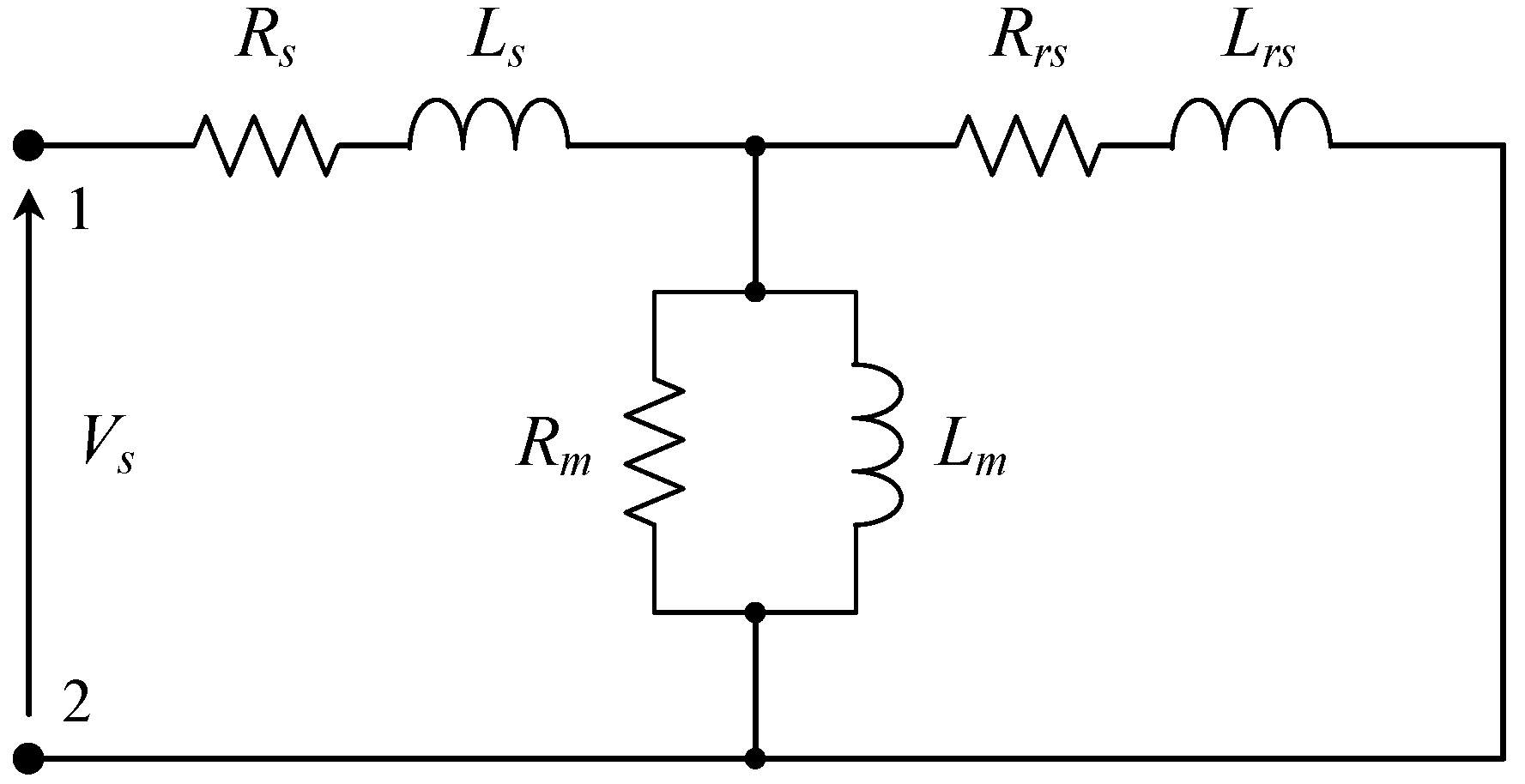
In order to analyse the high-frequency behaviour of IM, the basic electrical scheme at a standstill is presented in Figure 1.
The model consists of stator resistance, Rs, and stator leakage inductance, Ls, rotor resistance, Rrs, and rotor leakage inductance, Lrs, both seen from the stator side, and the magnetizing branch with parallel resistance, Rm, and inductance, Lm. For the higher order harmonics, the stator and rotor resistances can be neglected due to the fact that stator and rotor leakage inductances dominate [4]. By omitting these two parameters, the equivalent circuit is simplified to just four parameters. The parallel connection between the rotor leakage inductance and magnetizing inductance can be replaced with just one inductance with the proper equivalent value. If the magnetizing inductance is much higher than the rotor leakage inductance, which is usually the case in IMs, the parallel connection can be considered as the rotor leakage inductance per se, where Lrs||Lm ≅ Lrs.
Such an assumption is made in this paper. After simplifying the proposed model, the equivalent impedance seen from the terminals 1 and 2 (Figure 1) can be derived:
where f is the frequency, and ω = 2πf is the angular frequency. The frequency dependent behaviour of the rotor leakage inductance in case of rotor bars having a depth, d, is presented in [10,13]:
where denotes the rotor leakage inductance at DC (in our case, at the lowest initial measured frequency [5,6,7]), and:
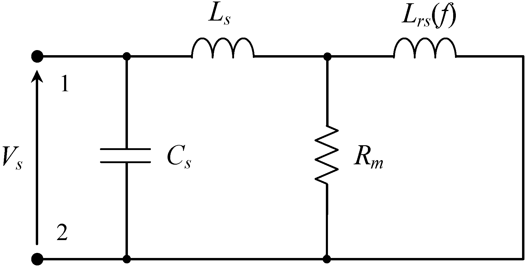
The relative permeability of free space in (3) is μo = 4π × 10−7 H/m and the resistivity of the aluminium bars is ρ = 2.65 × 10⁻⁸ Ω·m. It can be noted that the behaviour of the rotor leakage inductance is inversely proportional to the square root of the frequency. In order to introduce the effect of stray capacitances for higher frequencies, the modified IM equivalent circuit at the standstill is presented in Figure 2.
The value of the capacitor, Cs, which is connected in parallel to the simplified circuit, is within the range of 0.5 nF to 5 nF [11,12]. Usually, the capacitive effect is not noticeable in the lower switching frequency range; however, in some particular cases, it has a relatively small contribution for higher frequencies. Considering the equivalent series resistance, R′, and inductance, L′, as defined in (1), and introducing the parallel capacitor, Cs, the overall equivalent inductance becomes:
3. Experimental Evaluation of Equivalent Inductance
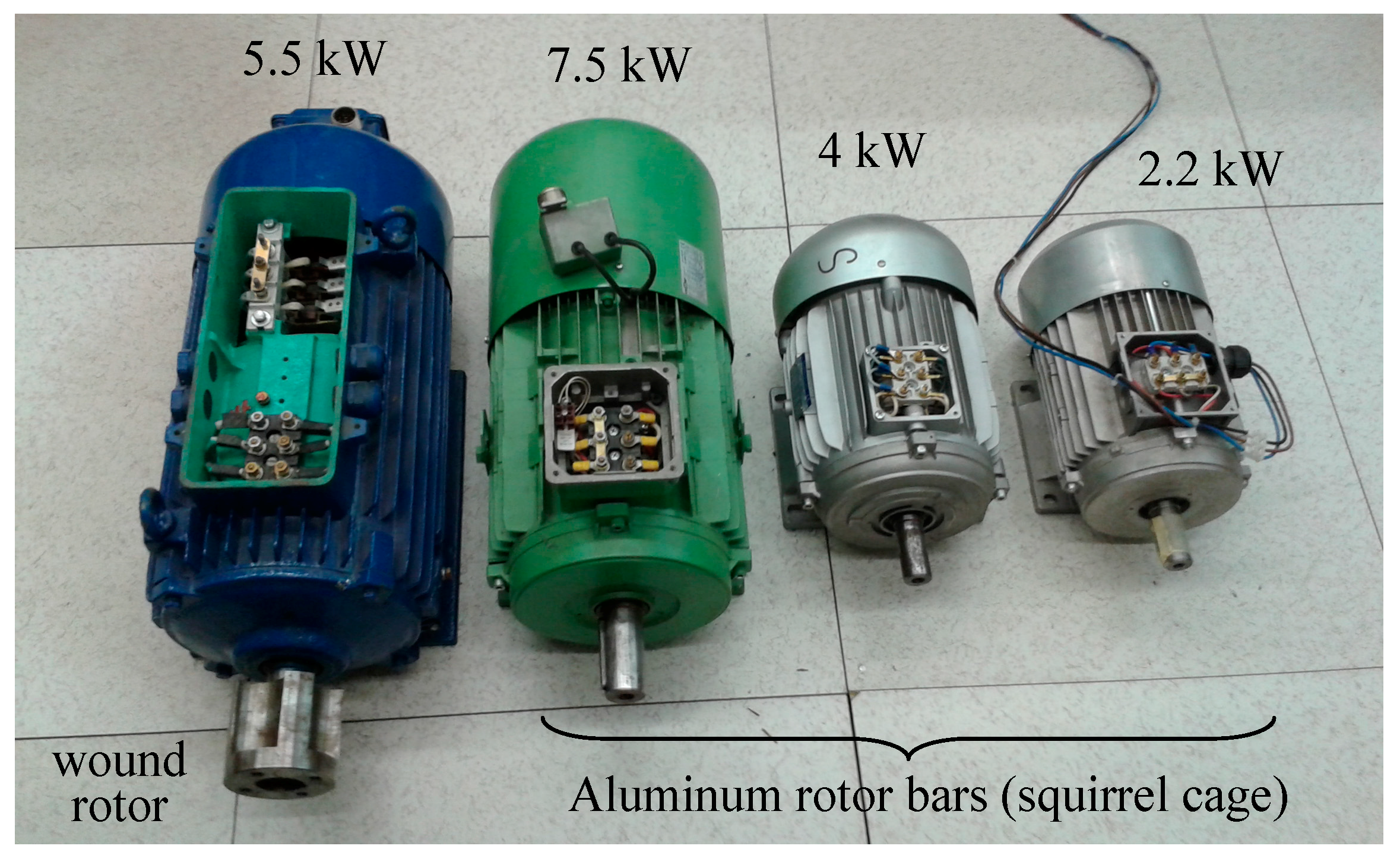
Experimental analyses were carried out in order to estimate the frequency dependent behaviour of the equivalent inductance of three-phase IMs and to verify the analytical developments based on the simplified equivalent circuit presented in Figure 2. The set of motors under investigation consists of four IMs with different rated power (see Figure 3). Three out of four tested IMs have squirrel-cage rotors, where the skin effect in aluminium rotor bars must be considered. The fourth one has wound-rotor windings, mainly used experimentally to emphasise the considerably less pronounced skin effect in such rotor windings.
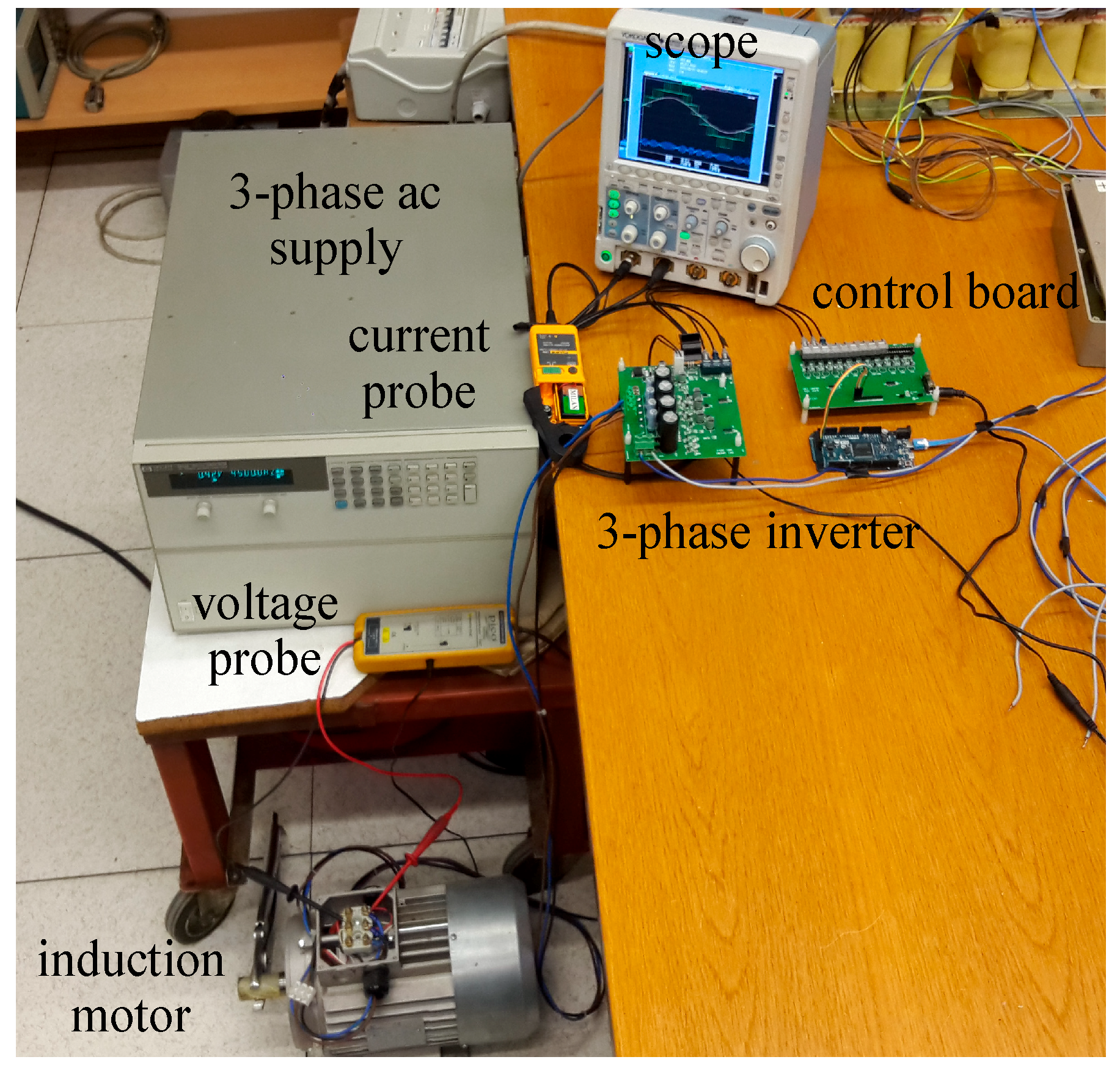
During measurements, each rotor shaft was mechanically locked to prevent its rotation. A three-phase sinusoidal power source, HP6834B (300 V, 4500 VA, 1Φ/3Φ, Keysight Technologies, Santa Rosa, CA, USA), was used for supplying the star-connected motors at a standstill. Due to its upper frequency limit of 5 kHz, in order to extend the test frequency range up to 20 kHz, a three-phase custom-made inverter operating in the six-step mode was used for the additional set of measurements, also guaranteeing almost sinusoidal motor currents. It consists of the three-phase IGBT Mitsubishi PS22A76 intelligent power module (1200 V, 25 A, Mitsubishi Electric Corporation, Tokyo, Japan) controlled by the Arduino Due microcontroller board (84 MHz Atmel, SAM3X83 Cortex-M3 CPU, Somerville, MA, USA). The Yokogawa DLM 2024 oscilloscope (Yokogawa Electric Corporation, Tokyo, Japan) with the PICO TA057 differential voltage probe (25 MHz, ±1400 V, ±2%, Pico Technology, Tyler, TX, USA) and LEM PR30 current probe (DC to 20 kHz, ±20 A, ±1%, LEM International SA, Plan-les-Ouates, Switzerland) were used to acquire motors’ phase voltage and current. The whole experimental setup is shown in Figure 4.
The measurement determines the equivalent impedance for all the four IMs, calculated as the ratio between rms values of fundamental components of the voltage and current in the frequency range from 1 kHz to 20 kHz, with an equidistant step of 1 kHz. The equivalent reactance, and consequently the equivalent inductance (seen from the stator side), was calculated based on the phase displacement between the two fundamental components. In addition, the same quantities were also determined at the motor rated frequency of 50 Hz. The built-in digital filters of the oscilloscope were used to properly handle the current and voltage waveforms.
To exclude the possible influence of voltage harmonics on the inductance measurements, a correlation between results acquired using the three-phase sinusoidal power source (up to 5 kHz) and the three-phase inverter with the six-step mode control was examined for all four motors. Comparing the results given in Table 2 for the 2.2 kW and 4.0 kW IMs clearly shows that the applied voltage source does not considerably influence the accuracy (within ±5%) of the determined equivalent inductance; therefore, only results for inverter supplied motors were presented to cover the whole frequency range from 1 kHz to 20 kHz. In Table 2, the parameter, Leq,~ represents the equivalent inductance measured in the case of the sinusoidal power source, Leq,inv denotes the equivalent inductance for the inverter supplied motor, and ε is the relative difference (in percent) between them.
Due to the voltage limitation of the supply source, it was not possible to perform the short circuit test at the rated current for the whole frequency range up to 20 kHz (the necessary voltage would also destroy the motor isolation). Therefore, the input inductance was determined at the same highest possible % of rated current for a particular IM. To evaluate the magnetizing conditions at lower currents than the rated stator currents and to eliminate possible mistakes in the determination of the equivalent inductance, verification tests with different currents were done for two motors at the rated frequency. The results presented in Table 3 show that the equivalent inductance, Leq, practically, does not change (regularly within ±5%), considering different test currents (Is).
The equivalent inductance, experimentally determined by the procedure described above, was compared with the value calculated by the proposed method (4), considering the motors’ parameters given in Table 4. The results show an acceptable agreement in the whole considered frequency range from 1 kHz to 20 kHz.
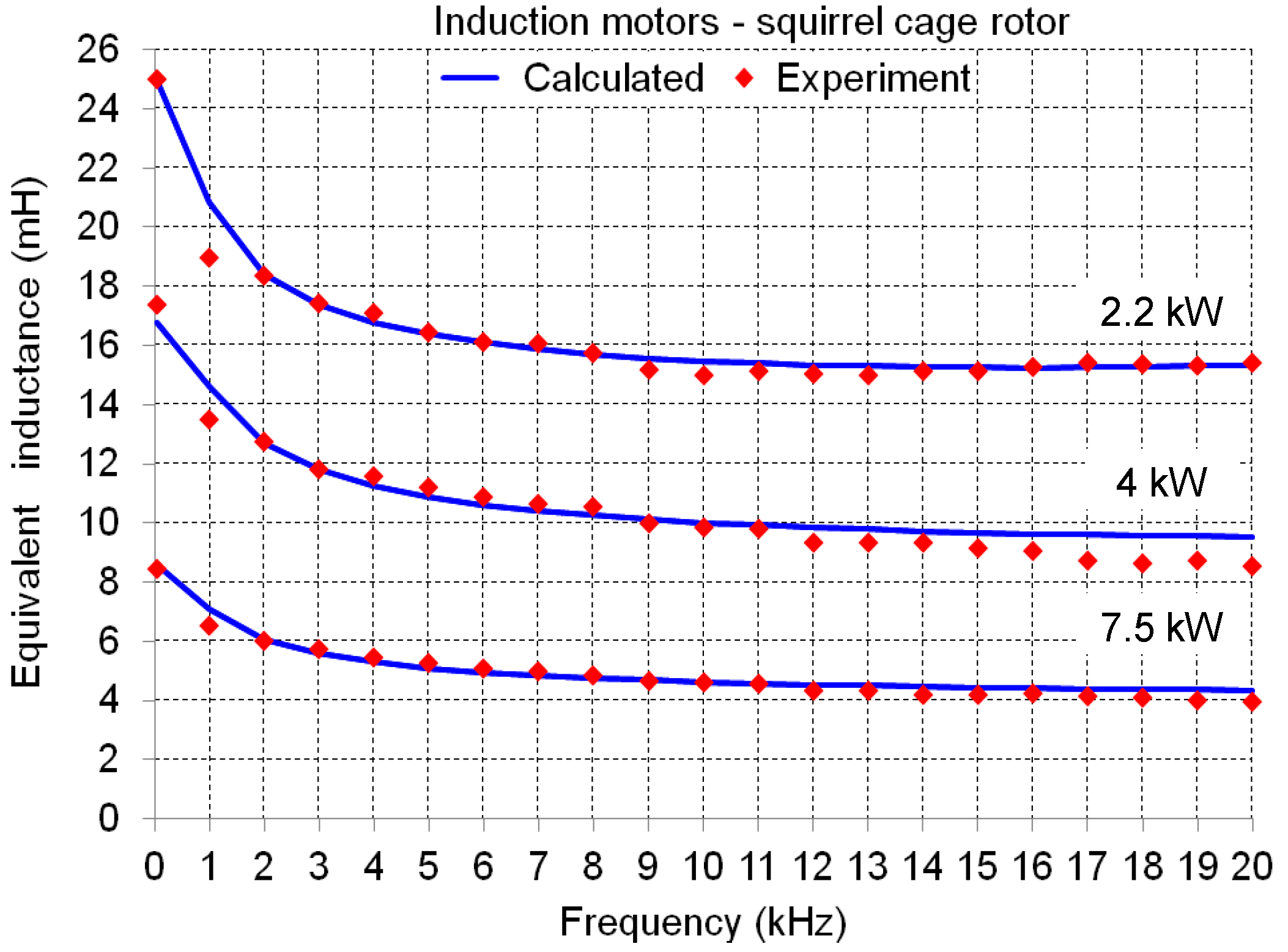
Particularly, in Figure 5, the case of IMs with rotor bars is presented, showing the expected decreasing behaviour of the equivalent inductance over the frequency due to the rotor leakage inductance frequency dependence. In the case of the 2.2 kW IM, the effect of stray capacitances is noticeable after the frequency of 15 kHz (modelled by the capacitor connected parallel to the equivalent circuit, Figure 2). The capacitive effects regarding the other two IMs (4 kW and 7.5 kW) are not visible within the considered frequency range.
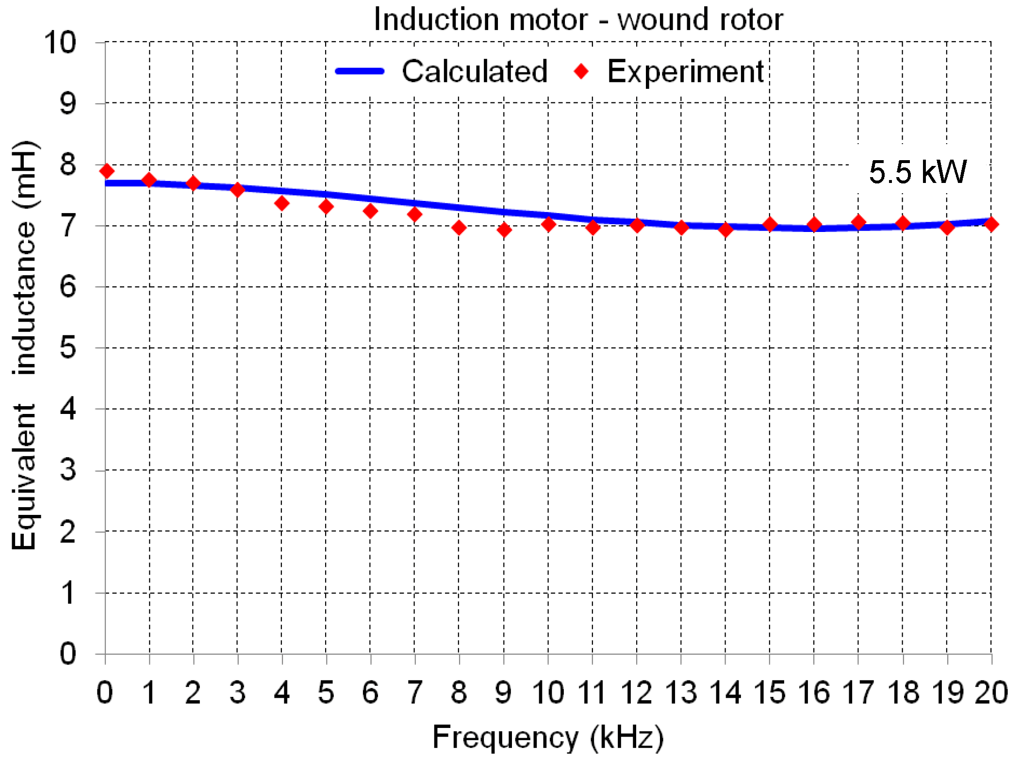
In the case of the IM with a wound rotor, as shown in Figure 6, the rotor leakage inductance is almost constant, with the skin effect being ineffective in such a rotor winding construction. The smooth decrease of the equivalent inductance is motivated by the resistive and reactive branches in the equivalent circuit (Figure 2), acting as a variable current divider as function of the frequency. A small increase of the Leq after 15 kHz is also noticeable, well represented by the parallel capacitor.
4. Application Example
When analysing the output current ripple regarding different PWM techniques and inverter configurations [9,14,15], the switching frequency and the load inductance are directly involved. In case of a squirrel-cage IM supplied by an inverter operating in the typical switching frequency range from 1 kHz to 20 kHz, and considering its equivalent inductance measured at a standstill at 50 Hz, this will result in a wrong current ripple estimation due to the frequency dependency of Leq, which could generally decrease more than 50% (Figure 5).
Experimental results were carried out in order to demonstrate the influence of Leq on the peak-to-peak current ripple amplitude in case of a three-phase squirrel-cage IM drive. The modulation technique used in this analysis was the space vector PWM technique, practically obtained by centering the three sinusoidal modulating signals of a carrier-based PWM with a common-mode injection (the so-called min/max injection).
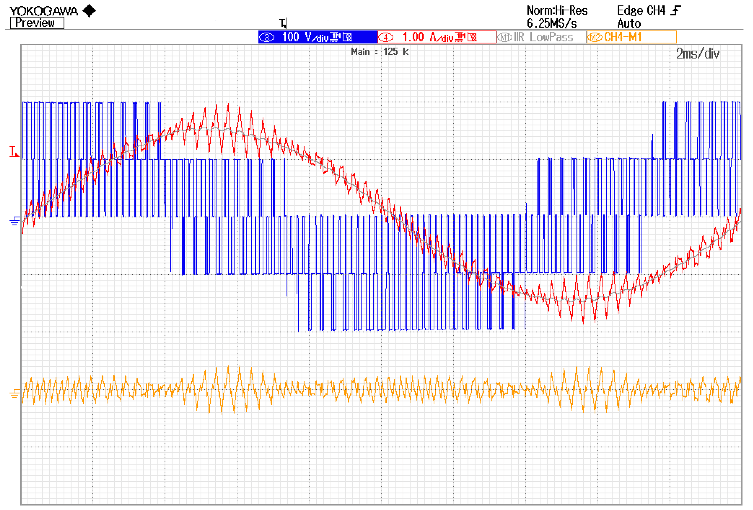
The IM under test is the first given one in Table 2; Table 4 (2.2 kW). Figure 7 shows the line-to-neutral voltage (blue trace), instantaneous output current (red trace), and its fundamental component (grey trace) and ripple (orange trace), over one fundamental period (20 ms). The presented case corresponds to the DC bus voltage of Vdc = 300 V, switching frequency of 3 kHz, and modulation index, m = 0.5 (mmax= 0.577). The current ripple was obtained by subtracting the fundamental component from the instantaneous current [15]. All waveforms in Figure 7 are given in real scales.
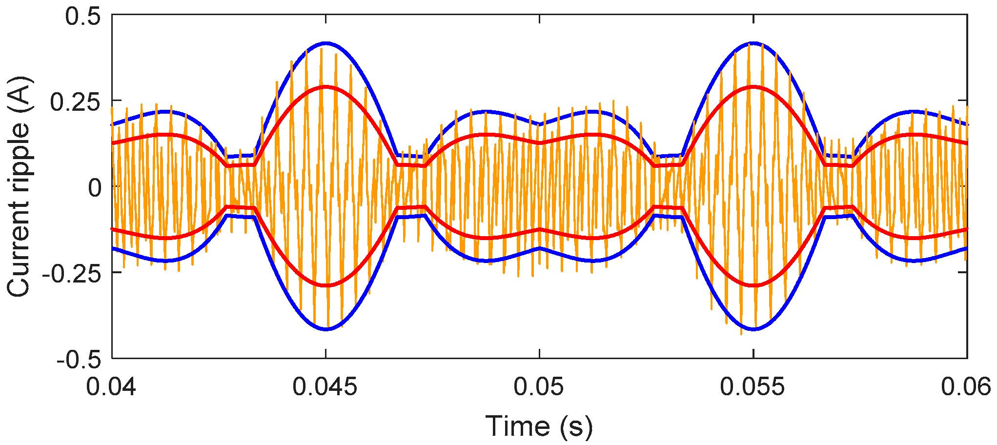
In Figure 8, the following waveforms are presented: Measured current ripple (orange trace, obtained by downloading the experimental data with a high sample resolution and post-processing in Matlab/Simu-link), current ripple envelope analytically calculated by using Leq = 17.36 mH, measured at fsw = 3 kHz (blue trace), and the current ripple envelope, analytically calculated by using Leq = 24.98 mH, measured at 50 Hz (red trace). The procedure of the current ripple envelope calculation is explained in detail in [9,14,15].
The results clearly emphasise the case of an incorrect current ripple estimation when considering Leq measured at the rated frequency instead of the switching frequency, giving a smaller current ripple amplitude (red envelope) compared with the correct one (blue envelope). Leq further changes with the switching frequency according to Figure 5. Such an explicit discrepancy may lead to several mismatches in the procedures of current ripple minimization, modulation strategies’ optimization, harmonic losses evaluation, EMC analysis, etc.
5. Conclusions
In this paper, the frequency-dependent behaviour of the IM equivalent inductance was presented in more detail compared to the existing literature. A simplified circuit model was proposed for induction motors in order to evaluate the equivalent inductance over the switching frequency range from 1 kHz to 20 kHz, which is the typical operating range of a PWM inverter in industrial ac motor drives.
Analytical results were compared with experimental ones, carried out by considering IMs with different rated powers, both squirrel-cage and wound-rotor types. The results show a good match, proving that the skin effect in rotor bars is mainly responsible for the equivalent inductance variation. There was huge variation in the frequency range up to 10 kHz, leading to a value that was 0.5 to 0.6 times more than the corresponding value measured at 50 Hz, depending on the IM design and power range. For higher frequencies, in the considered range up to 20 kHz, the equivalent inductance was almost constant. Thus, while selecting the switching frequency, it is very important to take into account the corresponding equivalent inductance, especially in the case of precise and sensitive motor control algorithms. The effect of stray capacitances was just noticeable, and it starts to be effective for frequencies higher than 20 kHz, which is already above the commonly used switching frequencies of mass-produced industrial inverters. More precise evaluation of the stray capacitance would require more complex circuits, instruments with higher resolution, and experiments in the capacitively-dominant working region; however, its influence is hardly noticeable in most cases. In the case of IM with wound rotor winding, the overall decrease of equivalent inductance was much less pronounced, and was not determined by the skin effect, and was well represented by the proposed circuit model. Apart from the presented analysis of the equivalent inductance, the evaluation of the equivalent resistance over the switching frequency range that is responsible for other relevant changes in some parameters could be performed in further research.
Author Contributions
Conceptualization, M.S. and G.G.; methodology, M.S., R.F., and G.G.; validation, M.S.; formal analysis, M.S., R.F. and G.G.; writing—original draft preparation, M.S.; writing—review and editing, R.F. and G.G..; funding acquisition, M.S.
Funding
This research received no external funding.
Conflicts of Interest
The authors declare no conflict of interest.
References
- Casadei, D.; Serra, G.; Tani, A.; Zarri, L. Theoretical and experimental analysis for the RMS current ripple minimization in induction motor drives controlled by SVM technique. IE 2004, 51, 1056–1065. [Google Scholar] [CrossRef]
- Kubo, H.; Yamamoto, Y.; Kondo, T.; Rajashekara, K.; Zhu, B. Current ripple analysis of PWM methods for open-end winding induction motor. In Proceedings of the 2014 IEEE Energy Conversion Congress and Exposition (ECCE), Pittsburgh, PA, USA, 14–18 September 2014. [Google Scholar]
- Dujic, D.; Jones, M.; Levi, E. Analysis of output current-ripple RMS in multiphase drives using polygon approach. PEL 2010, 25, 1838–1849. [Google Scholar] [CrossRef]
- Jones, M.; Dujic, D.; Levi, E.; Prieto, J.; Barrero, F. Switching ripple char-acteristics of space vector PWM schemes for five-phase two-level voltage source inverters—Part 2: Current ripple. IA 2011, 57, 2799–2808. [Google Scholar]
- Calin, M.; Rezmerita, F.; Ileana, C.; Iordache, M.; Galan, N. Performance analysis of three phase squirrel cage induction motors with deep rotor bars in transient behavior. Electr. Electron. Eng. 2012, 2, 11–17. [Google Scholar] [CrossRef]
- Potter, B.A.; Shirsavar, S.A.; Mcculloch, M.D. Study of the variation of the input impedance of induction machines with frequency. IET Electr. Power Appl. 2007, 1, 36–42. [Google Scholar] [CrossRef]
- Novotny, D.W.; Nasar, S.A.; Jeftenic, B.; Maly, D. Frequency depend-ence of time harmonic losses in induction machines. In Proceedings of the ICEM, Boston, FL, USA, 13–15 August 1990. [Google Scholar]
- Jiang, D.; Wang, F. Current ripple prediction for three-phase PWM converters. IA 2014, 50, 531–538. [Google Scholar] [CrossRef]
- Grandi, G.; Loncarski, J.; Dordevic, O. Analysis and comparison of peak-to-peak current ripple in two-level and multilevel PWM inverters. IE 2015, 62, 2721–2730. [Google Scholar] [CrossRef]
- Kwon, Y.S.; Lee, J.H.; Moon, S.H.; Kwon, B.K. Standstill parameter identification of vector-controlled induction motors using the frequency characteristics of rotor bars. IA 2009, 45, 1610–1618. [Google Scholar]
- Hidaka, T.; Ishida, M.; Hori, T.; Fujita, H. High-frequency equivalent cir-cuit of an induction motor driven by a PWM inverter. Electr. Eng. Jpn. 2001, 135, 65–76. [Google Scholar] [CrossRef]
- Grandi, G.; Casadei, D.; Reggiani, U. Equivalent circuit of mush wound AC windings for high frequency analysis. In Proceedings of the ISIE, Guimarães, Portugal, 7–11 July 1997. [Google Scholar]
- Cho, K.R.; Seok, J.K. Induction motor rotor temperature estimation based on high-frequency model of a rotor bar. IA 2009, 45, 1267–1275. [Google Scholar]
- Grandi, G.; Loncarski, J.; Srndovic, M. Analysis and minimization of output current ripple for discontinuous pulse-width modulation techniques in three-phase inverters. Energies 2016, 9, 380. [Google Scholar] [CrossRef]
- Loncarski, J.; Leijon, M.; Srndovic, M.; Rossi, C.; Grandi, G. Comparison of output current ripple in single and dual three-phase inverters for electric vehicle motor drives. Energies 2015, 8, 3832–3848. [Google Scholar] [CrossRef]
Figure 1.
Basic per-phase equivalent circuit of the IM at a standstill.

Figure 2.
Proposed per-phase equivalent circuit of IM in the switching-frequency range, including stray capacitance and a simplified RL network.
Figure 2.
Proposed per-phase equivalent circuit of IM in the switching-frequency range, including stray capacitance and a simplified RL network.

Figure 3.
The considered set of IMs under testing.

Figure 4.
Experimental setup for measuring frequency dependence of Leq.

Figure 5.
Model and experimental results for Leq vs. supply frequency for three squirrel-cage IMs.

Figure 6.
Model and experimental results for Leq vs. supply frequency for the rotor-wound IM.

Figure 7.
Details of experimentally obtained line-to-neutral voltage (blue trace), instantaneous current (red trace), fundamental current (grey trace), and current ripple (orange trace) for the 2.2 kW IM supplied by a three-phase inverter (centered PWM): Vdc = 300 V, fsw = 3 kHz and m = 0.5.
Figure 7.
Details of experimentally obtained line-to-neutral voltage (blue trace), instantaneous current (red trace), fundamental current (grey trace), and current ripple (orange trace) for the 2.2 kW IM supplied by a three-phase inverter (centered PWM): Vdc = 300 V, fsw = 3 kHz and m = 0.5.

Figure 8.
Measured current ripple (orange trace) and calculated current ripple envelopes (blue trace: Leq measured at fsw = 3 kHz, red trace: Leq measured at 50 Hz).
Figure 8.
Measured current ripple (orange trace) and calculated current ripple envelopes (blue trace: Leq measured at fsw = 3 kHz, red trace: Leq measured at 50 Hz).


Table 1.
Rated parameters of tested induction motors.
| IM | Squirrel Cage Rotor | Wound Rotor | |||
|---|---|---|---|---|---|
| Power (kW) | 2.2 | 4.0 | 7.5 | 5.5 | |
| Voltage (V) | 400 | 400 | 400 | Stator | Rotor |
| 380 | 186 | ||||
| Current (A) | 5.2 | 9.2 | 15.3 | 14.0 | 19.5 |
| Frequency (Hz) | 50 | 50 | 50 | 50 | |
| Speed (r/min) | 1400 | 1425 | 1450 | 1400 | |
Table 2.
Variance of equivalent inductance with two different supplies.
| IM | 2.2 kW | 4.0 kW | ||||
|---|---|---|---|---|---|---|
| fsw (kHz) | Leq~ (mH) | Leq,inv (mH) | ε (%) | Leq~ (mH) | Leq,inv (mH) | ε (%) |
| 1 | 19.43 | 18.95 | +2.53 | 13.53 | 13.49 | +0.29 |
| 2 | 17.95 | 18.37 | −2.39 | 12.37 | 12.76 | −3.06 |
| 3 | 17.63 | 17.44 | +1.09 | 11.60 | 11.83 | −1.94 |
| 4 | 17.09 | 17.11 | −0.12 | 11.06 | 11.57 | −4.41 |
| 5 | 16.79 | 16.46 | +2.00 | 10.66 | 11.20 | −4.82 |
Table 3.
Variance of equivalent inductance at reduced stator currents.
| IM 2.2 kW | ||||||
| Is (A) | 5.2 (*) | 4 | 3 | 2 | 1 | 0.35 |
| Leq (mH) | 23.56 | 23.44 | 24.04 | 24.64 | 24.04 | 25.02 |
| ε (%) | 0.00 | −0.51 | +2.04 | +4.58 | +2.04 | +6.19 |
| IM 4.0 kW | ||||||
| Is (A) | 9.2 (*) | 7 | 5 | 3 | 1 | 0.33 |
| Leq (mH) | 16.20 | 16.56 | 15.83 | 16.49 | 16.41 | 16.30 |
| ε (%) | 0.00 | +2.22 | -2.28 | +1.79 | +1.30 | +0.62 |
* Rated current.
Table 4.
Equivalent circuit parameters of tested induction motors.
| IM | Squirrel-Cage Rotor | Wound-Rotor | ||
|---|---|---|---|---|
| Power (kW) | 2.2 | 4.0 | 7.5 | 5.5 |
| Cs (nF) | 0.25 | 0.1 | 0.1 | 3.5 |
| Ls (mH) | 13 | 8.8 | 4 | 4 |
| (mH) | 12 | 8 | 4.6 | 3.7 |
| Rm (Ω) | 500 | 150 | 80 | 350 |
| d (mm) | 6 | 5 | 5.5 | — |
© 2019 by the authors. Licensee MDPI, Basel, Switzerland. This article is an open access article distributed under the terms and conditions of the Creative Commons Attribution (CC BY) license (http://creativecommons.org/licenses/by/4.0/).
Share and Cite
MDPI and ACS Style
Srndovic, M.; Fišer, R.; Grandi, G. Analysis of Equivalent Inductance of Three-Phase Induction Motors in the Switching Frequency Range. Electronics 2019, 8, 120. https://doi.org/10.3390/electronics8020120
AMA Style
Srndovic M, Fišer R, Grandi G. Analysis of Equivalent Inductance of Three-Phase Induction Motors in the Switching Frequency Range. Electronics. 2019; 8(2):120. https://doi.org/10.3390/electronics8020120
Chicago/Turabian StyleSrndovic, Milan, Rastko Fišer, and Gabriele Grandi. 2019. "Analysis of Equivalent Inductance of Three-Phase Induction Motors in the Switching Frequency Range" Electronics 8, no. 2: 120. https://doi.org/10.3390/electronics8020120
Note that from the first issue of 2016, this journal uses article numbers instead of page numbers. See further details here.