

Python Framework for Modular and Parametric SPICE Netlists Generation

1
TIMA Laboratory, University Grenoble Alpes, 38100 Grenoble, France
2
CNRS, 38000 Grenoble, France
*
Author to whom correspondence should be addressed.
Electronics 2023, 12(18), 3970; https://doi.org/10.3390/electronics12183970
Submission received: 14 August 2023
/
Revised: 9 September 2023
/
Accepted: 13 September 2023
/
Published: 20 September 2023
(This article belongs to the Special Issue Design of Mixed Analog/Digital Circuits, Volume 2)
Abstract
:Due to the complex specifications of current electronic systems, design decisions need to be explored automatically. However, the exploration process is a complex task given the plethora of design choices such as the selection of components, number of components, operating modes of each of the components, connections between the components and variety of ways in which the same functionality can be implemented. To tackle these issues, scripts are used to generate designs based on high-level abstract constructions. Still, this approach is usually ad hoc and platform dependent, making the whole procedure hardly reusable, scalable and versatile. We propose a generic, open-source framework tackling rapid design exploration for the generation of modular and parametric electronic designs that is able to work on any major simulator.
1. Introduction
Design complexity, ultra-low-power requirements, reliability, robustness and security are becoming increasingly important concerns when designing electronic systems. Due to the increasing complexity of analogue circuits, it is more difficult to design and assess their performance. Moreover, the aggressive scaling of CMOS technology makes the process of testing the same design under different technologies very tedious, as normally the process has to be repeated for every technology node. Moreover, the aggressive scaling of CMOS technology makes the process of testing the same design under different technologies very tedious, as the circuit needs to be redesign from scratch to account for the different technology characteristics. Furthermore, several issues must be considered at design time such as fabrication-induced variability, technology-dependent defects, extreme operating/environmental conditions, stochastic behaviours, ageing and possible perturbations (noise, radiations, malicious attacks). All these factors make the verification and testing of each circuit an arduous process.
To explore the behaviour of an electrical circuit under different designs and conditions, multiple iterations and simulations need to be performed under the desired environment. The interdependencies of large and complex circuits can quickly become a significant challenge due to the extensive amount of choices at play. Design space exploration (DSE) examines the different possibilities and design options within the allowed design space considering the constraints and requirements in order to fulfil the specified performance goals. DSE normally involves the use of tools as well as high-level abstract models of the system, to automate and streamline the exploration process since the design space is too large to be explored by hand. There is an interest in the industry to accelerate this process and reduce the time between iteration cycles. Computer Aided Design (CAD) and Electronic Design Automation (EDA) have drastically improved in recent decades, thanks to new methodologies, tools (i.e., cadence, synopsys, xyce) and very recently the addition of artificial intelligence, like genetic algorithms [1,2] or machine learning.
The idiosyncrasies of some technologies are very well understood and can be translated to higher levels of abstraction. However, with the present issues faced by today’s designs, electrical-level simulations are unavoidable since they allow designers to accurately model and understand the behaviour of the target system. They are a crucial pillar of analogue and mixed signal design space exploration, simulation of circuit under the presence of perturbations and research of novel computation paradigms. But unlike digital circuits, where the low-level phases of the design process are automated using fairly standard methodologies, synthesis and layout of analogue circuits are still carried out manually or through some sort of ad hoc automated solution.
In this paper, we show a Python framework [3] for the generation of modular and reusable electronic designs through the use of powerful manipulation primitives. The purpose of this framework is twofold: (i) to provide tools to create electrical components whose characteristics can be expressed through dynamic models or defined by logical rules and (ii) to provide powerful manipulation primitives to quickly create complex arrangements of components in a simple fashion. This framework benefits from the utilities and flexibility of a programming language like Python to generate modular and re-usable components. The designs created in Python can then be converted to any text format specified by the user (special focus on SPICE netlists). The framework is focused on the quick generation of complex designs. However, users could write extensions to automatically simulate the generated designs or perform other tools such as Electrical Rule Checker (ERC).
This paper is organised as follows: the current state of the art is summarised in Section 2, followed by the motivation for this project in Section 3. In Section 4, the framework is described in detail and some use cases are provided in Section 4.4. Future lines of work are discussed in Section 5, and, finally, our conclusions are extracted in Section 6.
2. State of the Art
There are currently a plethora of tools available that tackle design space exploration. Chisel [4] and PyMTL3 [5] provide frameworks with a high abstraction level that are able to compile a high level language code, like Scala and Python, into fully functional Verilog code for hardware description. In this way, circuit designers have the expressiveness and power of a programming language in order to quickly create reusable circuits. These tools target Register Transfer Level (RTL) and thus are not very well suited for analogue and mixed signal designs.
PySpice [6] is an utility to generate SPICE netlists and launch simulations by embedding the design and the simulator configuration under the same language, which facilitates the whole design iteration process. However the simulator is limited to NGspice and Xyce and the netlists can only be exported for PCB designs. Skidl [7] is a layer built on top of PySpice that attempts to to facilitate the process of connecting different components. SPICE netlists are the universal format that any available electronic simulator uses, albeit each simulator has it’s slightly different format. Our framework seeks to provide designs for any available simulator by providing the necessary tools to export the designs to different.
Alongside these tools, there are projects that provide automatic layout generation mechanism. One of the most famous known tools in this category is Magic [8]. Magic (available online at http://opencircuitdesign.com/magic/) is an interactive software for creating and modifying very large scale integration (VLSI) circuit layouts. Its most important feature is the creation of a layout and plowing it to scale it for different technology nodes. The ease of use of this utility comes with a penalty of 5 to 10% increase in area usage. Other tools found online like LibreCell [9] try to reduce this tradeoff by reducing the fan of possibilities that are provided to the user. Lower level tools such as GDSTK [10] and GDSFactory [11] enable the creation and manipulation of GDSII and OASIS files, which are the standard file format for foundries to specify circuit layouts. These tools can be used as the basis of a much more complete software that is able to generate the layout based on a circuit definition. Researchers have also put focus on intelligent methodologies for automatic layout generation for both PCB [12,13,14] and ASIC [15]. Genetic algorithms have proven very useful and performant for this type of tasks.
AIDA [16] is a tool that tackles analogue IC sizing and layout. It provides powerful utilities to perform parametric analysis, where the underlying parameters and properties of a circuit can be generated and swapped in place before every simulation cycle. However, the user needs to generate the design beforehand, which does not solve the issue of design exploration.
There are complete projects like OpenRAM [17] that provide a Python framework to create the layout, netlists, timing and power models, placement and routing models to use SRAMs in ASIC design. This tool provides an easy interface to configure the characteristics of the SRAM. This is a very powerful tool but is limited to SRAMs and a selected number of technology nodes (currently NCSU FreePDK 45 nm, MOSIS 0.35 μm and Skywater 130 nm).
3. Motivation
The proposed framework focuses on providing utilities that enables users to perform quick design space exploration and parametrization of electronic designs. A high-level abstract interface is provided in order to create modular and reusable components, that can be seamlessly parametrised in order to provide users a general overview of the design under different design constraints and environments.
The advantage of using a programming language like Python as an abstraction layer to generate circuits is that we are not limited by a drag-and-drop graphical user interface and we can exploit the expressiveness of Python to quickly generate complex structures as well as having support for the plethora of available scientific libraries. Graphical Interfaces tend to change in time, while a programming language stays fixed. This eliminates the need of learning different software and users can quickly start designing. Moreover, changes in the design are represented as changes in the source code which can make the process of versioning much simpler. Moreover, using a tool that is properly debugged and formalised provides also the advantage of not having to check the finished netlist, whereas in the case where the netlist is created by hand, it needs to be checked and corrected for every modification.
Most of the commercially available software provides an interface to perform parametric analysis on a design. However, if we want to generate different versions of a circuit, each version has to be generated by hand (e.g., a flash ADC with different number of bits), thus reducing the possible space of exploration due to time or complexity constraints. With our tool, parametric characteristics can be embedded directly into the components and the multiple designs can be generated in a modular and programmable fashion.
Furthermore, most of the available tools that perform automatic circuit generation are either closed-source or they are application-specific tools (e.g., SRAM generators). The Python tools described in the section before (PySpice and Skidl) are focused on PCB design, which is out of the scope of this paper.
4. Overview of the Tool
4.1. Electrical Components and Parameters
The parameters of an electronic component can be described easily with a Python dictionary. They can also be defined defined statically or dynamically calculated (i.e., through Python functions or SymPy formulas, that may not be available or accessible in EDA tools). Dynamic parameters bring the possibility of embedding parametric analysis directly into the circuit definition. These parameters can be grouped into ParamSets that behave similar to process corners. The following example shown in Listing 1 shows a reduced number of parameters for a NMOSFET transistor, where the vth of the transistor is drawn from a Gaussian distribution.
| Listing 1. Example parameters for a NMOSFET transistor where the vth is defined dynamically. |
 |
In order to automatically generate parameters from files that are commonly used, this framework provides a parser interface to extract information from different file formats and Process Design Kits (PDKs). Multiple parsers are already available but users can extend this functionality by defining their own custom parsers. Certainly this functionality makes the process of testing different technology nodes or constraints more accessible, as the parameters and component names can be updated in the moment and swapped in place depending on the desired environment. Since the parsing and translation procedures are independent processes, users can read data from one SPICE format and output their new design to a different format, which enables quick prototyping.
This also allows a progressive adaptation of the framework by users, or easy change between different architectures. The same complex circuit can be generated using different basic cells by providing netlists that defined the same subcircuit defined in different architectures. The example shown in Listing 2 describes how a netlist can be parsed and converted into a Circuit object that we can manipulate in Python. The parser also retrieves information about directives so simulators can also be configured directly from the Circuit object.
| Listing 2. Example netlist containing multiple spectre directives a subcircuit definition and 2 instances. |
 |
The previous netlist is parsed into the following Python object.
 |
Electronic components themselves can be created through the Component class as it is shown in Listing 3. Besides the basic properties like component name, connected nets and parameters, users can embed metadata to provide additional information that can be shared between different tools. These components serve as templates to generate the modular circuits. Since electrical components can be treated as black boxes with inputs, outputs and parameters. Other type of components, like the ones described in Verilog-A, can also be used without problem (as long as the simulator accepts them) as it is shown in Listings 3, 9 and 10.
| Listing 3. Example creation of a capacitor and a custom NMOS model. The parameters are extracted from a file using an example Reader. |
 |
Once the components have been defined, it can be instantiated multiple times by using the operators @ and % which are overloaded to quickly modify the connections and the parameters of a component.
4.2. Manipulations and Operations
As it has been show in Section 2, there are already tools that allow to generate netlists. The core objective of this framework is to provide very efficient manipulation primitives to quickly create complex and reusable connection patterns that can be customised through variables. This framework provides a small list of operations that can be used to create more complex patterns, like the Parallel and Chain operations that create components in parallel and in a daisy chain as their name imply. The manipulations automatically instantiate the number of desired components and update their connections or parameters as it can be seen in Listing 4. In this way, the connection between components occurs in a deterministic and reusable way so it’s easier to avoid mistakes when connecting components, which could minimise the need of Electrical Rule Checking (ERC) tools.
| Listing 4. Example of the basic manipulation operations. |
 |
Although only a limited number of manipulations are already provided by the library, users can use them to create and extend their own manipulation operations. The components generated by a manipulation can be accessed and modified directly. This ease of modification is handy to simulate process-induced variability or even to evaluate the resilience of a system to faults or errors. Said faults can be injected, as an example, into a list of components and their behaviour can be measured. In the Listing 5, the manipulation Inject receives a chain of components and a probability of defect injection. For each component in the chain it has a chance of generating the desired defect and connecting it to the output of the component. We can also see in this example how the Inject and Chain manipulation can be concatenated to produce the desired circuit.
| Listing 5. Example of defect injection in a chain of 7 transistors. |
 |
Another useful manipulation is the Array, which that allows instantiating components in a 1D or 2D array and their connections can be updated dynamically trough their coordinates, as it is shown in the Listing 6. This array generation utility can be of great use to create crossbar arrays, two-dimensional CMOS sensors and Micro Electro-Mechanical Systems (MEMS) matrix that contain a very large number of components.
| Listing 6. Example of 2D crossbar array. The size of the array is determined by the arr_size variable. |
 |
The previous code results in the following netlist. We can see that the array dimensions is parametrized and we can quickly create very large 1D or 2D arrays.

Both 2D and 1D arrays are very easy to implement with this framework due to the expressiveness of Python. The following examples shown in Listing 7 illustrate how easy it is to implement a chain and a matrix of components just by exploiting the list comprehensions or for loops. The matrix of size is generated using only two lines. While this example is intentionally simple, it can be more complex for example by providing different parameters depending on the position of the component in the matrix or chain. These type of modular circuits can be easily created since they be mapped from a mathematical construct, like vectors, arrays or recursive formulas, directly into programming constructs like loops or lists, that can then be shortened through Python expressions, like lists comprehension.
| Listing 7. Example of a matrix and component chain generation using list comprehensions. |
 |
It is this direct mapping from mathematical to programming constructs that allow generating large number of parametric components very easily. This means that the weakness of this framework lies on circuits that cannot described easily with loops or by composition of basic blocks and it does not offer any advantage over the usual CAD tools. But in this case we can argue that is infeasible to create a tool for the automatic generation of a non modular or reusable circuit.
To allow for reusable designs and more complex logic, multiple components can be grouped inside a subcircuit, just like SPICE subcircuits. Subcircuits can be fixed so that no more components can be added. This can be used to stop the addition of components in a loop based on logical tests. Once a subcircuit has been defined, it can be used as a component and thus the manipulation primitives can be applied. The components and subcircuits created can be grouped inside a Circuit. A circuit behaves very similarly to a SPICE netlist and can be then converted into a subcircuit to be used in other designs. This is the one of the main interfaces for code re-usability and modular designs.
4.3. Exporting Elements
All the elements created can be exported to text files so that they can be shared between different utilities or read back in a later future. Moreover, this framework provides an interface to export the elements to different file formats that users can extend to create their desired exporters. This process makes the framework simulator agnostic, as the same design can be exported to different simulators just by using different Exporters as it is shown in the Listing 8. Furthermore, users are not only bounded to simulators as the different components and nets can be exported to other kind of file formats for analysis.
| Listing 8. Example exporting a design into a file. |
 |
4.4. Circuit Examples
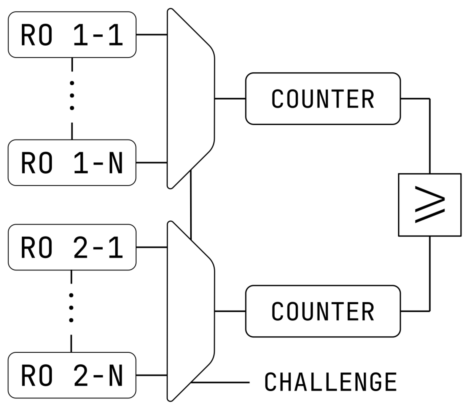
This tool has been used to create the circuits used in the study [20]. A ring oscillator is a chain of inverters, designed normally as shown in Figure 1, that oscillates when an input signal is applied to the first inverter in the chain due to the gate delay. Multiple of this ring oscillators can be connected to multiplexers that allow the selection of a pair of ring oscillators. The output signal of the multiplexer can be fed to a counter to measure the oscillation frequency of the ring oscillators.
In the Listing 9, it is shown a detailed example, where the number of inverters per ring oscillator and the total number of chains are determined by the N_RO_PER_CHAIN and N_CHAINS variables, respectively. The number of inputs of the multiplexer can be defined dynamically also from the N_CHAINS variable. The Counter component has been created in Verilog-A.
| Listing 9. Example of creating the ring oscillator chains. |
 |
As it has been said before, the framework is not limited to basic HDL components. Any kind of component that is valid in SPICE can be created with this framework. As an example, the BSIM Common Multi-Gate Model (BSIM-CMG) http://bsim.berkeley.edu/models/bsimcmg/ (accessed on 12 September 2023) which allows FinFET to be modelled, can be used directly by many SPICE simulators, even if the model is described in Verilog-A. The component, called bsimcmg_va, needs to be created in the Python code to instantiate FinFET transistors, as the Listing 10 shows.
| Listing 10. FinFET component through the BSIM-CMG model. |
 |
Other type of circuits that could benefit from this framework are Analogue to Digital Converters (ADC) and Digital to Analogue Converters (DAC).
5. Discussion
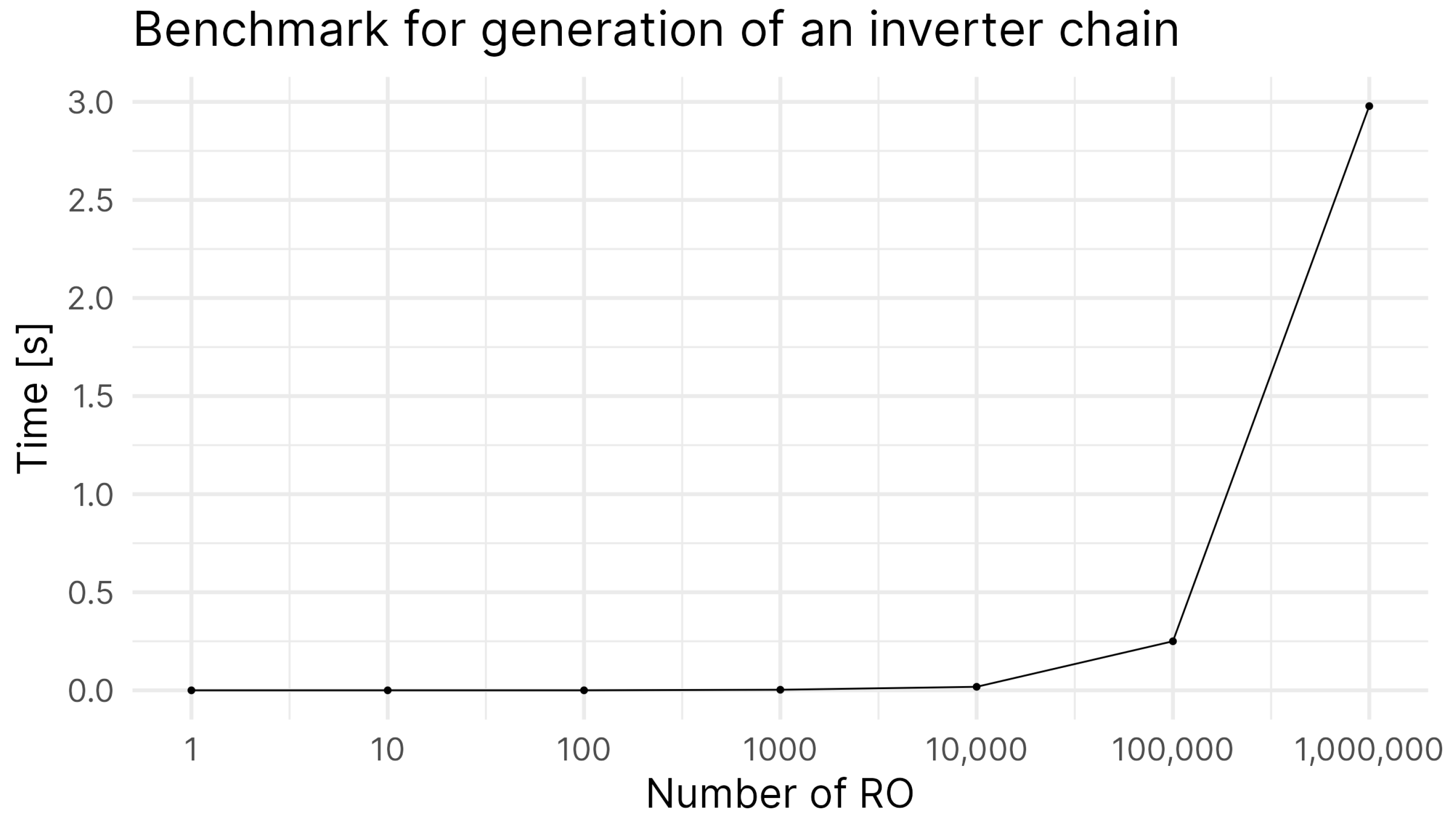
The framework described here is a powerful interface between Python and SPICE. It can be used as the basis to implement more complex methodologies such as prototyping, design optimisation and variability simulations. Other advantages of using Python to generate netlists is the speed improvement, as compared to generating the circuit by hand. The framework does not impose any time overhead as it can be seen from the next benchmark. The framework is able to create create 1 million instances in approximately 4 s and the SPICE netlist itself can be exported in less than 2 s as it can be seen from the results of a benchmark in Figure 2.
These benchmarks were performed on a ASUS ZenBook (Intel® Core™ i5-8250U processor 1.6 GHz Quad-core, 8 GB RAM DDR3 sourced from ASUS, Madrid, Spain). The graph from the benchmark shows that the initial time complexity of the generation of components is linear. However, the time complexity of the circuit generation is heavily dependent on the circuit itself. If components are simply instantiated directly in the circuit, the time complexity is . If every instance needs to run a specific calculation of each instance (e.g., unique parameter values) the time complexity can quickly increase. However, due to the nature of most test circuits, the timing overhead of this tool should be negligible, specially when iterating multiple times since most transient simulations can take minutes or even hours to finish.
Moreover, we have at our disposition all the tools provided by a fully fledged programming language, so the generated circuit can be debugged and formalized programatically, whereas in the case where the netlist is created by hand, it needs to be checked and corrected for every modification.
This framework allows us to create subcircuits or certain instances from another tool (e.g., Cadence), parsing already created circuits from netlists, modify them in place (for example to perform process variability simulations) or extend them by creating the circuit depending on a user defined configuration (e.g., macro compilers for SRAM, MACs, chains, etc). As such, it was not designed to substitute the commercially available CAD tools, rather boost the designer productivity by easing the process of working with modular circuits.
This framework has been used successfully for memristive-based computing in-memory [21] in order to find the best configuration of size and voltage.
6. Conclusions
The framework proposed in this article provides tools focused on fast design space exploration and modular and re-usable electronic designs. Electronic circuits are modelled through the use of Python objects that allow for easy manipulation and quick iteration cycles. The examples provided above show how the framework excels at generating modular architectures and can adapt to multiple technologies and devices. Moreover, the electrical components can be imported from a plethora of file formats and the designs can be exported to various SPICE formats suitable for any available simulator.
Author Contributions
Software, S.V.G.; supervision, E.-I.V. and G.D.N. All authors have read and agreed to the published version of the manuscript.
Funding
This research received no external funding.
Informed Consent Statement
Not applicable.
Data Availability Statement
The software is open source under the MIT license and is available online at https://servinagrero.github.io/nimphel, accessed on 12 September 2023.
Conflicts of Interest
The authors declare no conflict of interest.
References
- Huang, G.; Hu, J.; He, Y.; Liu, J.; Ma, M.; Shen, Z.; Wu, J.; Xu, Y.; Zhang, H.; Zhong, K.; et al. Machine learning for electronic design automation: A survey. Acm Trans. Des. Autom. Electron. Syst. (TODAES) 2021, 26, 1–46. [Google Scholar] [CrossRef]
- Zebulum, R.S.; Pacheco, M.A.; Vellasco, M.M.B. Evolutionary Electronics: Automatic Design of Electronic Circuits and Systems by Genetic Algorithms; CRC Press: Boca Raton, FL, USA, 2018. [Google Scholar]
- Gutierrez, S.V. Nimphel. Available online: https://servinagrero.github.io/nimphel (accessed on 12 September 2023).
- Bachrach, J.; Vo, H.; Richards, B.; Lee, Y.; Waterman, A.; Avižienis, R.; Wawrzynek, J.; Asanović, K. Chisel: Constructing hardware in a scala embedded language. In Proceedings of the DAC Design Automation Conference 2012, San Francisco, CA, USA, 3–7 June 2012; IEEE: New York, NY, USA, 2012; pp. 1212–1221. [Google Scholar]
- Jiang, S.; Pan, P.; Ou, Y.; Batten, C. Pymtl3: A python framework for open-source hardware modeling, generation, simulation, and verification. IEEE Micro 2020, 40, 58–66. [Google Scholar] [CrossRef]
- Salvaire, F. Pyspice. Available online: https://pyspice.fabrice-salvaire.fr (accessed on 12 September 2023).
- Vandenbout, D. Skidl. Available online: https://devbisme.github.io/skidl/ (accessed on 12 September 2023).
- Ousterhout, J.K.; Hamachi, G.T.; Mayo, R.N.; Scott, W.S.; Taylor, G.S. The magic vlsi layout system. IEEE Des. Test Comput. 1985, 2, 19–30. [Google Scholar] [CrossRef]
- Kramer, T. Librecell. Available online: https://codeberg.org/librecell (accessed on 12 September 2023).
- Gabrielli, L.H. Gdstk. Available online: https://github.com/heitzmann/gdstk (accessed on 12 September 2023).
- Gdsfactory. Available online: https://github.com/gdsfactory/gdsfactory (accessed on 12 September 2023).
- Nielsen, A.A.; Der, B.S.; Shin, J.; Vaidyanathan, P.; Paralanov, V.; Strychalski, E.A.; Ross, D.; Densmore, D.; Voigt, C.A. Genetic circuit design automation. Science 2016, 352, aac7341. [Google Scholar] [CrossRef] [PubMed]
- Jain, S.; Gea, H.C. Pcb layout design using a genetic algorithm. J. Electron. Packag. 1996, 118, 11–15. [Google Scholar] [CrossRef]
- Chapman, C.D.; Saitou, K.; Jakiela, M.J. Genetic algorithms as an approach to configuration and topology design. J. Mech. Des. 1994, 116, 1005–1012. [Google Scholar] [CrossRef]
- Shahookar, K.; Mazumder, P. A genetic approach to standard cell placement using meta-genetic parameter optimization. IEEE Trans.-Comput.-Aided Des. Integr. Circuits Syst. 1990, 9, 500–511. [Google Scholar] [CrossRef]
- Lourenço, N.; Martins, R.; Canelas, A.; Povoa, R.; Horta, N. Aida: Layout-aware analog circuit-level sizing with in-loop layout generation. Integration 2016, 55, 316–329. [Google Scholar] [CrossRef]
- Guthaus, M.R.; Stine, J.E.; Ataei, S.; Chen, B.; Wu, B.; Sarwar, M. Openram: An open-source memory compiler. In Proceedings of the 2016 IEEE/ACM International Conference on Computer-Aided Design (ICCAD), Austin, TX, USA, 7–10 November 2016; pp. 1–6. [Google Scholar]
- Casper, T.; Duque, D.; Schöps, S.; Gersem, H.D. Automated netlist generation for 3d electrothermal and electromagnetic field problems. J. Comput. Electron. 2019, 18, 1306–1332. [Google Scholar] [CrossRef]
- Youssef, S.; Javid, F.; Dupuis, D.; Iskander, R.; Louerat, M.-M. A python-based layout-aware analog design methodology for nanometric technologies. In Proceedings of the 2011 IEEE 6th International Design and Test Workshop (IDT), Beirut, Lebanon, 11–14 December 2011. [Google Scholar]
- Sergio, V.G.; Di Natale Giorgio, V.E.-I. On-line reliability estimation of ring oscillator puf. In Proceedings of the IEEE Electronic Test Symposium 2022, Barcelona, Spain, 23–27 May 2022. [Google Scholar]
- Inglese, P.; Vatajelu, E.I.; Natale, G.D. On the limitations of concatenating boolean operations in memristive-based logic-in-memory solutions. In Proceedings of the 2021 16th International Conference on Design & Technology of Integrated Systems in Nanoscale Era (DTIS), Montpellier, France, 28–30 June 2021. [Google Scholar]
- Jehng, Y.-S.; Chen, L.-G.; Parng, T.-M. Asg: Automatic schematic generator. Integration 1991, 11, 11–27. [Google Scholar] [CrossRef]
- Naveen, B.; Raghunathan, K. An automatic netlist-to-schematic generator. IEEE Des. Test Comput. 1993, 10, 36–41. [Google Scholar] [CrossRef]
Figure 1.
Schematic of a ring oscillator physical unclonable function.

Figure 2.
Benchmark for the generation of Inverter chains. X axis in logarithmic scale.

Disclaimer/Publisher’s Note: The statements, opinions and data contained in all publications are solely those of the individual author(s) and contributor(s) and not of MDPI and/or the editor(s). MDPI and/or the editor(s) disclaim responsibility for any injury to people or property resulting from any ideas, methods, instructions or products referred to in the content. |
© 2023 by the authors. Licensee MDPI, Basel, Switzerland. This article is an open access article distributed under the terms and conditions of the Creative Commons Attribution (CC BY) license (https://creativecommons.org/licenses/by/4.0/).
Share and Cite
MDPI and ACS Style
Vinagrero Gutiérrez, S.; Di Natale, G.; Vatajelu, E.-I. Python Framework for Modular and Parametric SPICE Netlists Generation. Electronics 2023, 12, 3970. https://doi.org/10.3390/electronics12183970
AMA Style
Vinagrero Gutiérrez S, Di Natale G, Vatajelu E-I. Python Framework for Modular and Parametric SPICE Netlists Generation. Electronics. 2023; 12(18):3970. https://doi.org/10.3390/electronics12183970
Chicago/Turabian StyleVinagrero Gutiérrez, Sergio, Giorgio Di Natale, and Elena-Ioana Vatajelu. 2023. "Python Framework for Modular and Parametric SPICE Netlists Generation" Electronics 12, no. 18: 3970. https://doi.org/10.3390/electronics12183970
Note that from the first issue of 2016, this journal uses article numbers instead of page numbers. See further details here.