1. Introduction
In recent years, the growth of electrical and electronic industries led to the broadening of the frequency spectrum and the increase in different sources of electromagnetic disturbances. Both magnetic field and high-frequency electromagnetic radiation may then coexist in a practical working environment. Thus, it is necessary to provide adequate shielding solutions, which cover a wide frequency band.
Metals are widely used in shielding applications due to their high conductivity and/or permeability. Conductive metals are known to shield high-frequency electromagnetic fields [
1,
2] thanks to eddy currents. Magnetic metals are able to shield low-frequency electromagnetic fields [
3,
4,
5] thanks to their capacity to channel magnetic flux. Multilayered shields or biphasic composite, combining both conductive and magnetic metals, give interesting results in different frequency ranges [
6,
7,
8,
9,
10]. Indeed, the authors previously observed the magnetic shielding effectiveness of a 230 μm Al/steel/Al composite is 8 dB at 10 kHz, higher than a single 250 μm Al layer, which is 6 dB [
6]. Similarly, Ma et al. [
8] elaborated a 1 mm Fe/Al/Fe composite and showed its static magnetic shielding effectiveness is around 10 dB, about 2.5 times that of a pure iron plate. Moreover, its electromagnetic shielding effectiveness reaches 40–70 dB in the frequency range of 30 kHz–1.5 GHz. Watanabe et al. [
9] showed the shielding effectiveness of a stack of five Cu(0.7 μm)NiFe(0.3 μm) layers is 37.6 dB at 40 MHz, 3.9 times higher compared with a 5 μm copper layer.
However, metals generally have a high mass density, and in order to reduce the mass of equipment and pollution, recent studies are focused on lightweight composites in bulk or foam structures based mainly on metal foams [
11], a polymer matrix with metallic particles [
12,
13], metallic fibers [
14], metallic microwires [
15,
16,
17], carbon nanotubes [
18,
19,
20], carbon fibers [
21,
22], or graphene [
23]. Carbon fillers are used in polymer composites for their lower conductivities than metallic fillers in order to reduce reflectivity. However, in counterpart, their shielding effectiveness is also lower. The electromagnetic shielding effectiveness of a 5 mm stainless-steel fibers/polymer composite is around 78 dB at 2 GHz with a filler content of 25 wt%, a fiber diameter of 8 μm, and an aspect ratio of 1000 [
14]. A 2 mm ferromagnetic microwires-graphene/silicone elastomer composite has maximum shielding effectiveness of 18 dB at 8.2–12.4 GHz with a 0.059 wt% filler content [
17]. In comparison, a 2 mm carbon nanotubes/epoxy foam composite has constant shielding effectiveness of around 23 dB between 12 and 18 GHz with a 5 wt% filler content [
19]. Thus, to reach similar shielding effectiveness, the filler content must be higher for carbon fillers than with metallic fillers. Those composites are nevertheless less conductive than bulk metals and show lower shielding effectiveness. Moreover, most studies on those composites are only focused on a limited frequency range, and mainly at a high frequency (GHz). The use of those composites in near-field applications is therefore not assured.
Thus, a composite that joins lightness and capacity to shield a large frequency band is still to be studied. In this context, the novelty of this work is to design a wide-frequency-band, lightweight, multilayered, composite shielding structure that can perform at very low and high frequencies, from 1 Hz to 20 GHz. This paper studies the shielding effectiveness of a trilayer composite associated with a support layer (SL) used for mechanical strength, a metallic magnetic layer (ML) for low-frequency shielding, and a conductive layer (CL) for high-frequency shielding. Initially, two possible structures are considered: ML/SL/CL and SL/CL/ML. In both cases, the SL, ML, and CL thicknesses are 2 mm, 23 μm (+25 μm of adhesive), and 50 μm, respectively. Such thickness values correspond to many practical cases related to embedded enclosures in automotive or aircraft vehicles. The small thicknesses of the ML and CL ensure the lightness of the composite.
The shielding effectiveness of the composite is evaluated with analytical and numerical models. In order to study the shielding effectiveness for a wide frequency range, two analytical models are used: The Moser model [
24] in the case of a near-field magnetic shielding at a low frequency and Schelkunoff decomposition [
25] in the case of a far-field plane wave shielding at a high frequency. Both models give accurate results in their specific frequency range. For example, Kühn et al. [
26] observed, in the case of an aluminum layer of 300 μm with an area of 0.3 m × 0.2 m, the near-field magnetic shielding effectiveness obtained from the Moser model is close to the experimental measurements, especially in the lower frequency range (f < 1 kHz). The frequency range f < 2.5 kHz is not described correctly by the Schelkunoff decomposition. Both the Moser model and Schelkunoff decomposition match the experimental results by 2.5 kHz to 200 kHz.
Moreover, two numerical models are also implemented in COMSOL Multiphysics: One with an AC/DC module for the near-field application and one with an RF module for the far-field application. Thin-layer modeling is quite challenging, especially for 3D applications. In order to simplify numerical calculations and consider integrating the proposed multilayered composite into future 3D models, a homogenization method [
6] and Artificial Material Single Layer (AMSL) method [
27] are used. The limits of these methods are determined by comparing the shielding effectiveness of the trilayer composite, the homogenized layer, and the artificial layer.
2. Materials and Electromagnetic Model
2.1. Materials
The SL, CL, and ML refer to a glass-fiber-reinforced epoxy composite, a graphene sheet, and a mu-ferro sheet, respectively. Mu-ferro is the commercial name for soft magnetic metal with a relative permeability within 10,000 and 25,000 at direct current [
28]. The properties of these materials are resumed in
Table 1. The conductivity is calculated from a resistivity measurement obtained by a four-probe method. The relative permeability of the mu-ferro sheet given in
Table 1 corresponds to those calculated in the near-field at 1 Hz and 1 MHz from experimental measurements. Further details will be specified in
Section 3.1. The change in permeability with frequency is considered in the developed model. For far-field applications (f > 1 MHz), its relative permeability is set to 1.
2.2. Analytical Models
The analytical model of Moser [
24] gives the shielding effectiveness (SE) for an infinite plane sheet illuminated by a magnetic field produced by a loop (near-field). In this model, the shield is centered between the emitting loop and the receiving loop. The SE is then defined as follows:
is the Bessel function of the first kind of order 1, is the propagation constant in the shield, is the free-space propagation constant, is the angular frequency, c is the free-space velocity of light, is the shield thickness, is the emitting loop radius, is the distance between the emitting loop and the receiving loop, (,) are, respectively, the free-space permittivity and permeability equal to F/m and H/m, and (,,) are, respectively, the relative permittivity, the relative permeability, and the conductivity of the shield. In all of our calculations, the relative permittivity is considered equal to 1.
The Schelkunoff decomposition [
25] gives the SE for an infinite plane sheet illuminated by a normal incident plane wave (far-field). The SE is defined as follows:
is the reflection coefficient, is the free-space wave impedance equal to 377 Ω, and is the shield impedance.
2.3. Numerical Models
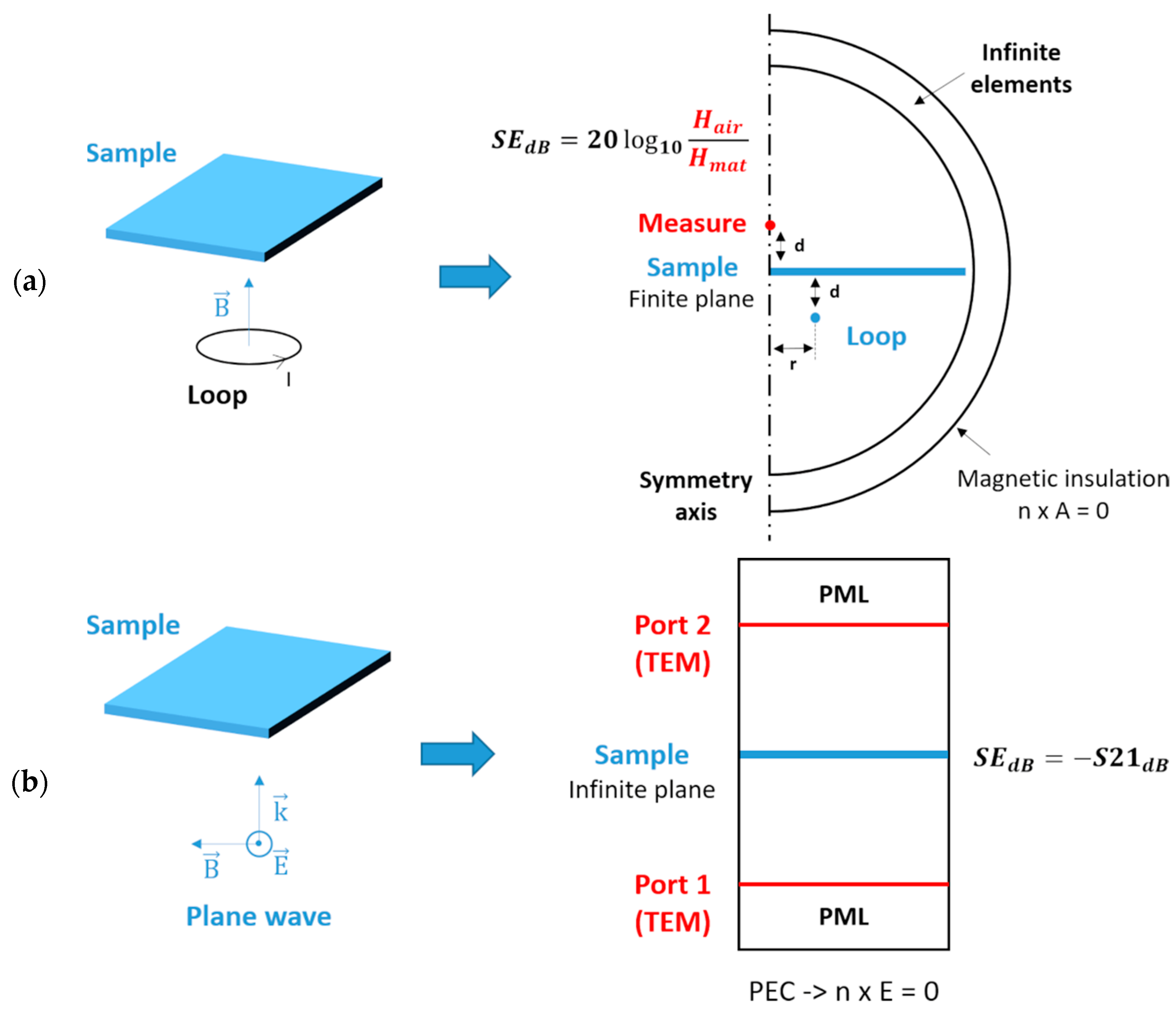
The geometries of the two numerical models, corresponding to analytical models, are represented in
Figure 1 for the near-field (a) and far-field (b) applications. For the near-field case, due to symmetry, the numerical model is developed in 2D-axisymmetric with the AC/DC module. A loop of a radius r of 1.5 cm illuminates the sample, modeled as a circular disc with a radius of 10.5 cm. The sample radius is 7 times the loop radius to approach the infinite plane assumption in the Moser model, which is not conceivable in this numerical model, while keeping an adequate computation time. The distance d between the loop and the sample and between the sample and the measuring point is fixed at 2 cm. A layer of infinite elements bounds the computational domain. The SE is calculated by computing the magnetic field on the symmetry axis with and without the sample.
For the far-field analysis, the numerical model is developed in 2D with the RF module. Two ports are defined, one emitting a transverse electromagnetic wave and one receiving it. Two layers of the Perfectly Matched Layer (PML) bound the model. The edges are defined as a Perfect Electric Conductor (PEC) for symmetry. The sample is in contact with the model edges to consider it as an infinite plane. The SE is directly related to the transmission loss S21dB.
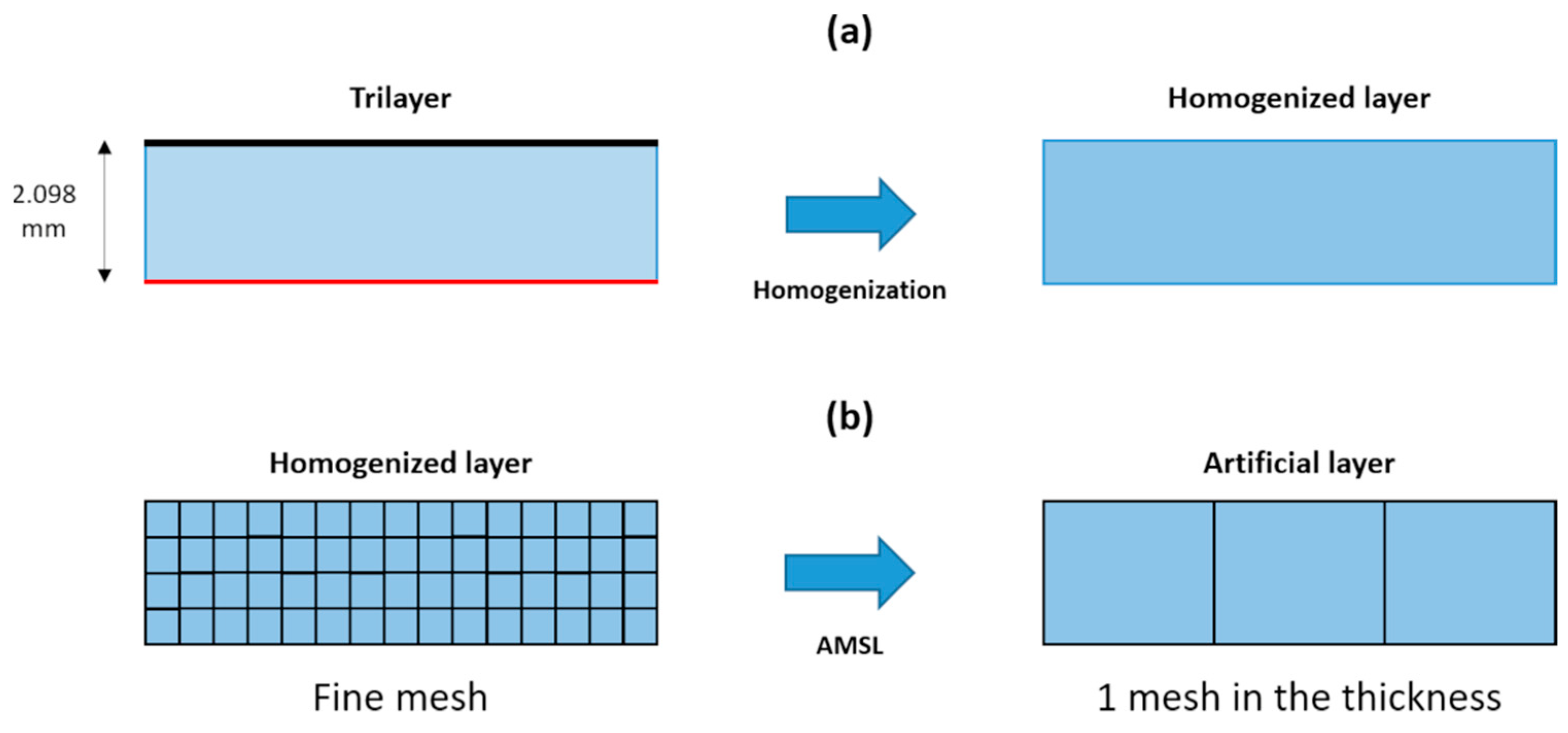
Figure 2 shows a schematic diagram of the homogenization (a) and the AMSL (b) methods. The homogenization method, based on an energetic approach at a direct current [
6], allows considering the trilayer composite as a homogenized layer with effective conductivity and permeability. Then, the AMSL method [
27] allows considering the homogenized layer as an artificial layer where only one element mesh is required in the thickness for the numerical calculation, instead of a standard fine mesh discretizing the homogenized layer.
3. Results and Discussion
3.1. Relative Permeability of the Mu-Ferro and SE of One-Material Sheet
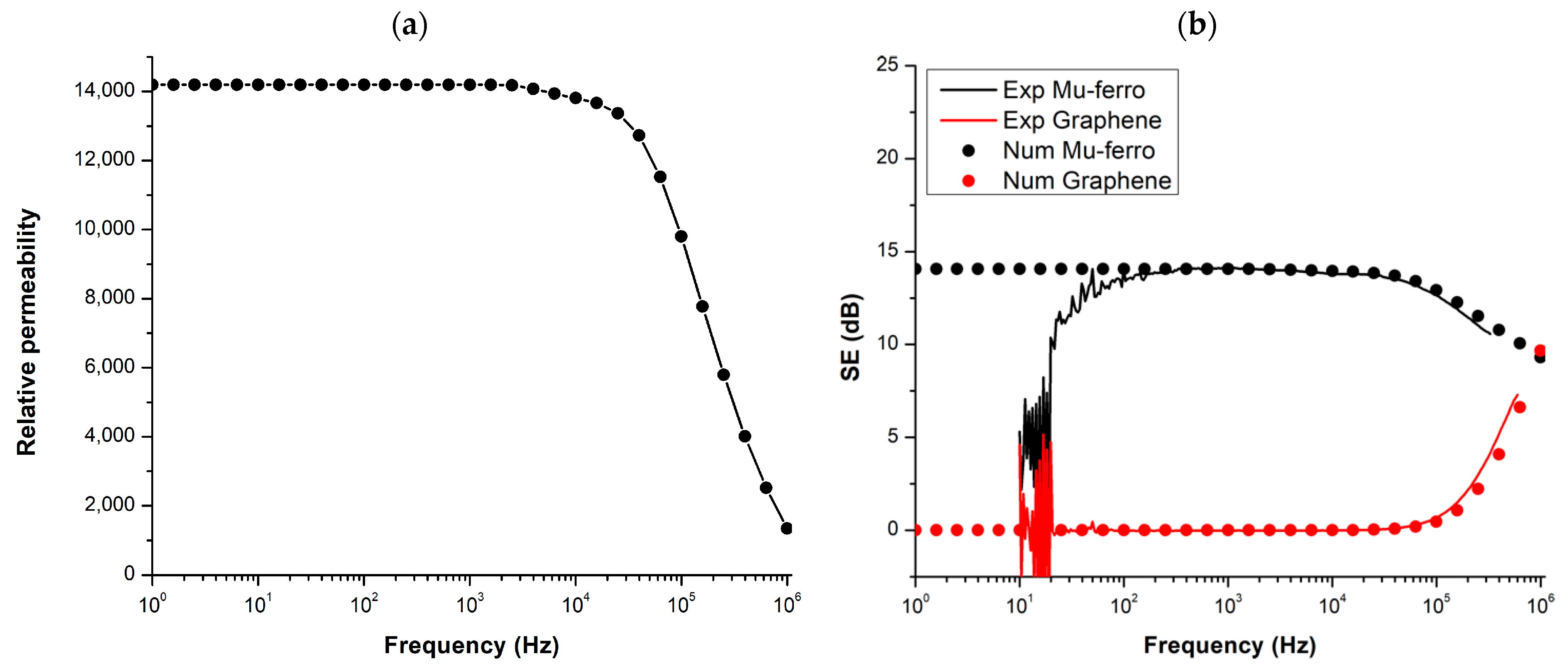
The relative permeability of the mu-ferro sheet is determined from experimental measurements. The experimental SE is measured with a gain-phase analyzer (HP 4194A) from 10 Hz to 1 MHz. The permeability is calculated by minimizing the difference between the SE obtained numerically with the 2D-axi model and the experimental one. The resulting relative permeability, plotted in
Figure 3a, is constant at 14,200, until around 2 kHz. For the case of a distance d of 3.05 cm, the experimental SE and the SE obtained from the numerical model for both mu-ferro and graphene layers are plotted in
Figure 3b. Experimental and numerical results show a good concordance from around 100 Hz where experimental measures are less noisy.
3.2. Layer Arrangements
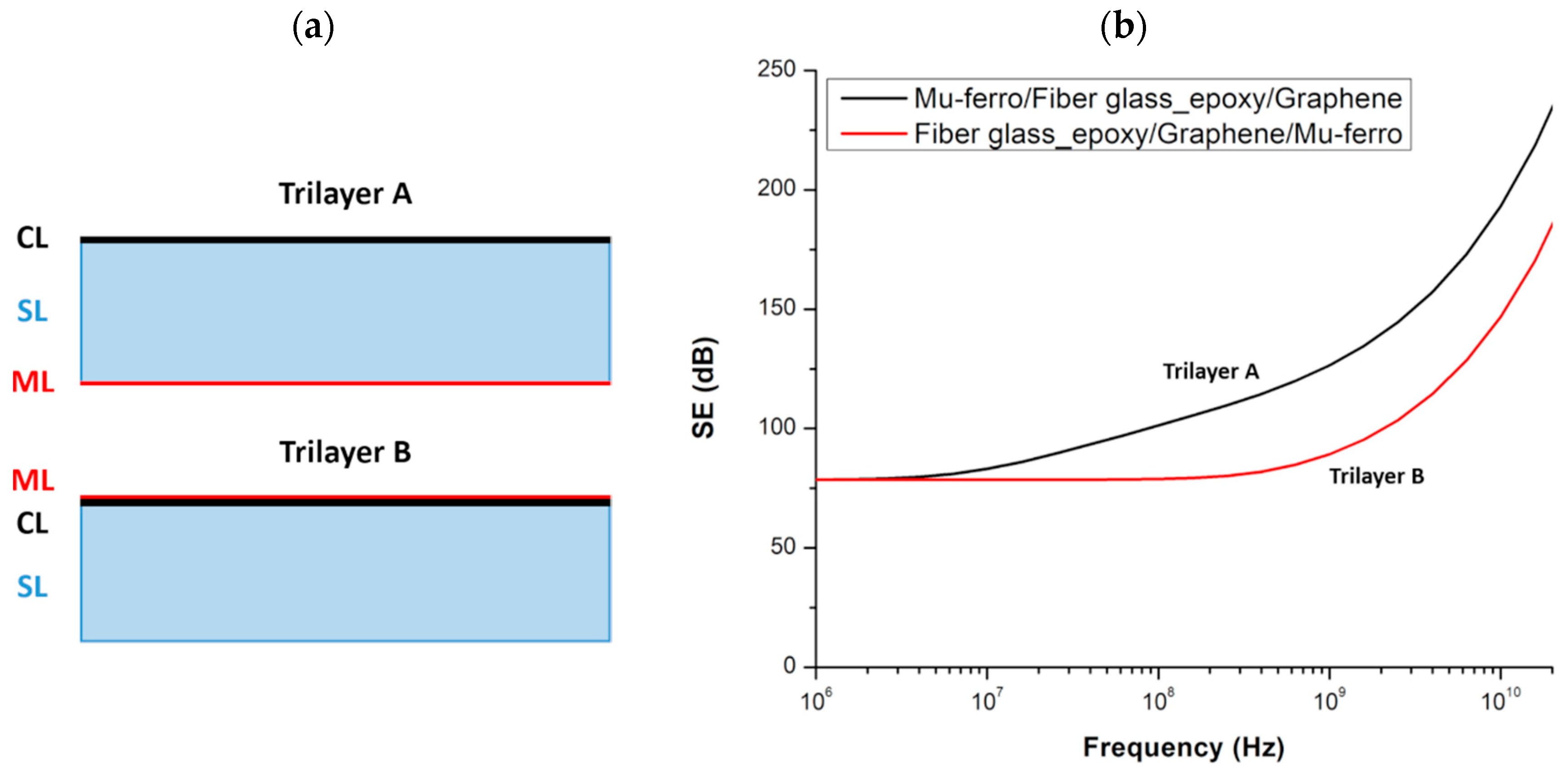
Initially, two layer arrangements are considered: The first case where the CL and the ML are separated by the SL, and a second case where both layers are on the same side of the SL (
Figure 4a). The SE for these two structures obtained numerically in far-field is plotted in
Figure 4b. It is observed that the SE of the ML/SL/CL composite is greater than the SE of the SL/CL/ML composite for frequencies higher than 2 MHz. As expected, no difference between the two layers’ arrangement is noted in the near-field for a low frequency.
3.3. Materials Contribution
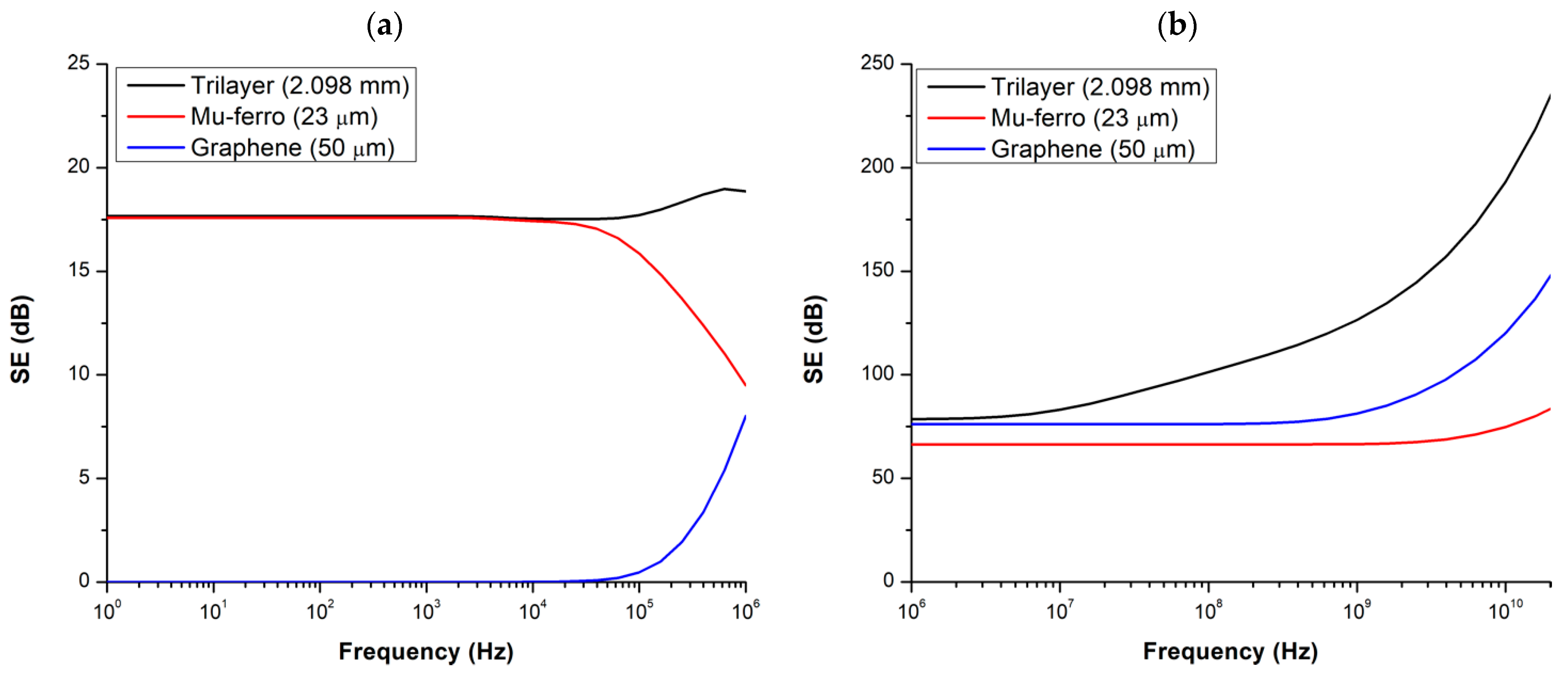
The SE of the trilayer composite, a single graphene layer, and a single mu-ferro layer is calculated in near-field from 1 Hz to 1 MHz and in the far-field from 1 MHz to 20 GHz. The results of the numerical models are presented in
Figure 5a,b, respectively, in the near-field and far-field.
In the near-field, thanks to its high relative permeability, the mu-ferro layer has an SE of 17.6 dB from 1 Hz to 10 kHz that then decreases to 9.5 dB at 1 MHz. The SE of the graphene layer increases only from 20 kHz. The trilayer composite shows both interesting behaviors with the capacity to shield at a low frequency thanks to the mu-ferro layer. Above 20 kHz, the decrease in SE with the frequency is compensated by an increase thanks to the graphene layer.
In the far-field, as both graphene and mu-ferro layers are conductive, their SE is high enough. By combining both layers, the SE of the trilayer composite is greater than 75 dB for the whole frequency range.
Note that the SE at 1 MHz in the near-field is different from the one in the far-field due to the different assumptions of AC/DC and HF approaches. As a consequence, AC/DC and RF modules of COMSOL Multiphysics are limited to their respective range of frequencies and give accurate results only in those frequency bands.
3.4. Validity of Homogenization and AMSL Methods
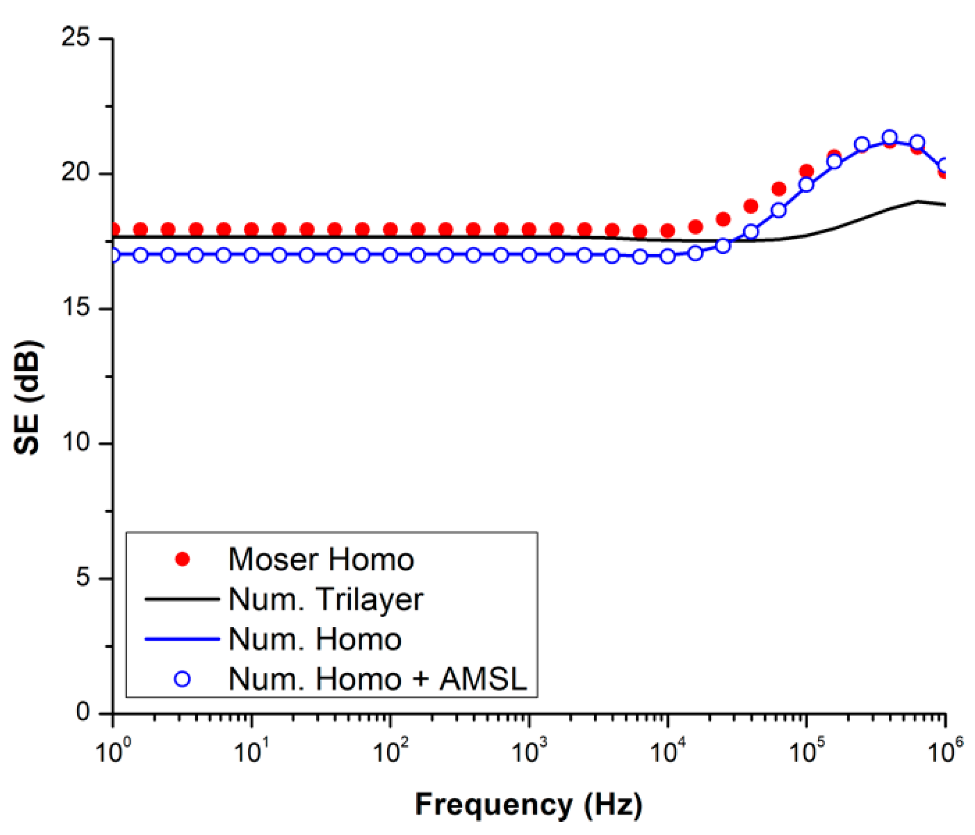
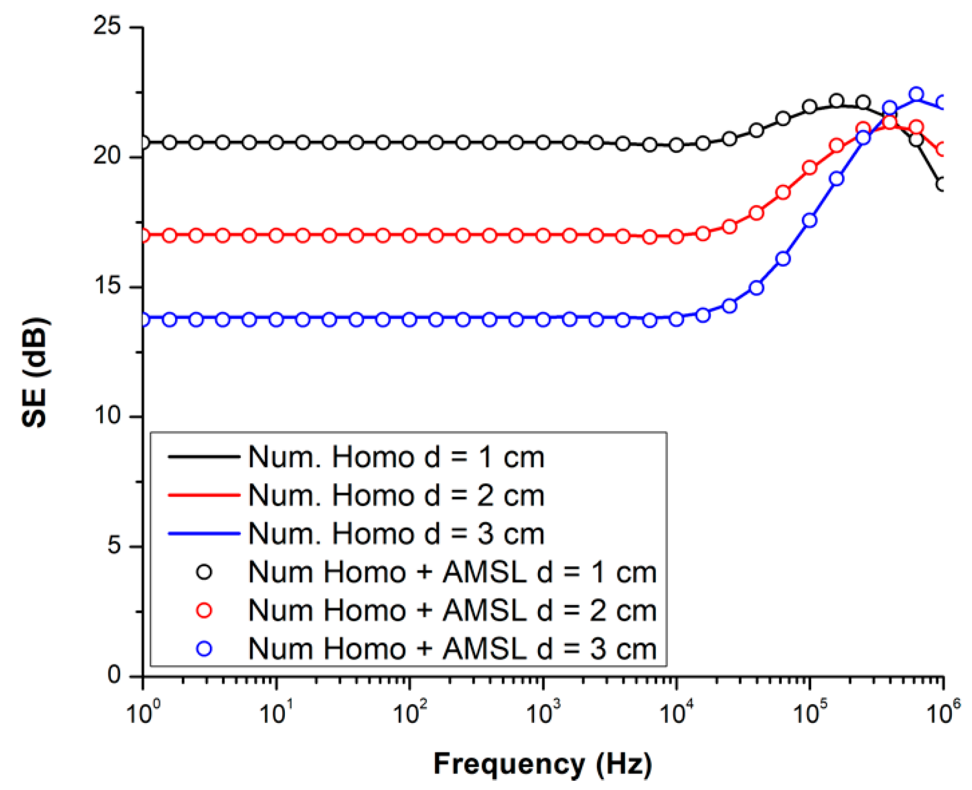
The results of the analytical model and numerical model in the near-field are compared for the trilayer study in
Figure 6. In the case of the numerical approach, the SE of the actual trilayer composite, the homogenized layer, and the artificial layer are plotted.
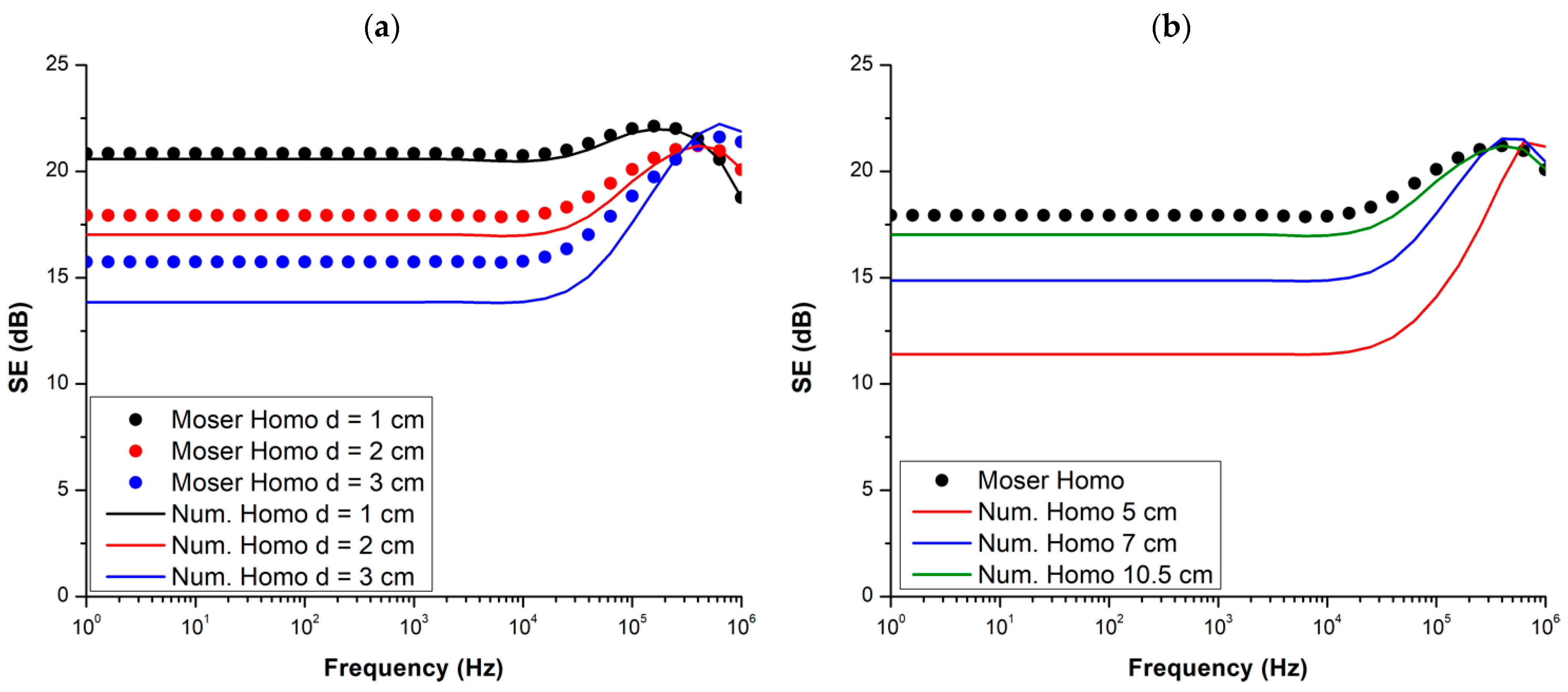
First, it should be noted that the Moser model was developed only for single layers and cannot be used for multilayers. Thus, in the near-field, the comparison between analytical and numerical models is performed with the homogenized layer. The SE of the homogenized layer obtained analytically with the Moser model and numerically presents a difference of around 0.9 dB at a low frequency. This difference is due to the finite dimensions of the composite in the numerical model. Indeed, by reducing the distance d between the loop and the sample, and between the sample and the measuring point, or by increasing the radius of the sample, the difference between analytical and numerical results decreases, as shown in
Figure 7a,b respectively. For a low frequency (<10 kHz), this difference is around 1.9, 0.9, and 0.3 dB for a distance d of 3, 2, and 1 cm, respectively. Reducing the sample radius in the numerical model deviates from the infinite plane assumption in the Moser model, and the difference is then greater at around 6.5, 3.1, and 0.9 dB, respectively, for a sample radius of 5, 7, and 10.5 cm.
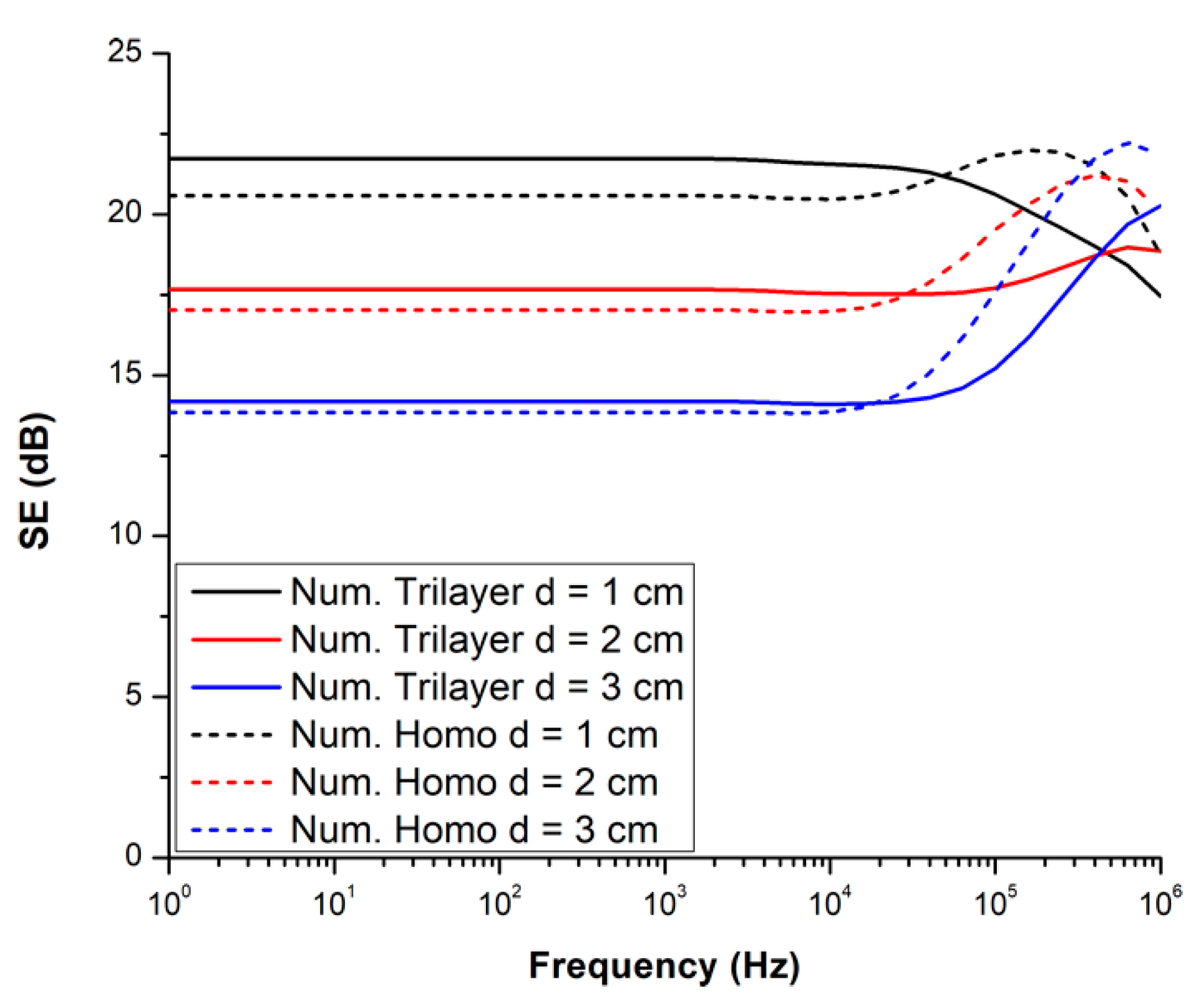
Comparing the numerical results, the SE of the actual trilayer composite is slightly higher, around 0.6 dB, at low frequencies than the SE of the homogenized layer. It is observed that this difference can be reduced by increasing the distance d, as shown in
Figure 8. For a low frequency (<10 kHz), this difference is around 1.1, 0.6, and 0.3 dB, respectively, for a distance d of 1, 2, and 3 cm. It can also be noted that the conductivity of the graphene layer is not sufficient to compensate for the decrease in the SE for higher frequencies when the emitting loop is close to the sample (d = 1 cm). The graphene layer is more impactful for higher distances.
Above 20 kHz, when the skin depth of the homogenized layer begins to be smaller than 2 mm, the SE of this layer rises more rapidly than the ones for the trilayer composite. This indicates that the homogenization method is less suitable for high frequencies when the skin depth is too thin compared to the total composite thickness.
The SE of the artificial layer is identical to the homogenized layer for the whole studied frequency range (see
Figure 6 and
Figure 9). As in the case of homogenization only, the AMSL method is then also limited to a low frequency when the skin depth is not too thin. However, both homogenization and AMSL methods allow for reducing the calculation time. Indeed, the calculation time with the trilayer composite is around 30 min, reduced to 8 min with the homogenized layer, and to only a few seconds with the artificial layer (processor: Intel(R) Core(TM) i5-8265U CPU @ 1.60 GHz, 8GB RAM).
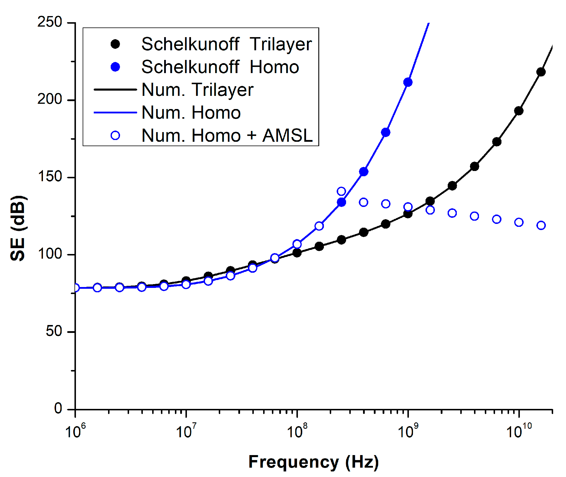
For the far-field study, the SE obtained analytically with Schelkunoff decomposition and numerically, plotted in
Figure 10, are identical for both the trilayer and homogenized layer since both methods considered an infinite plane.
However, as observed in the near-field approach, the SE of the homogenized layer increases more rapidly with the frequency than the trilayer one, indicating that the homogenization method is not suitable for high frequencies (>60 MHz). Similarly, the AMSL method is not appropriate for high frequencies (>250 MHz).
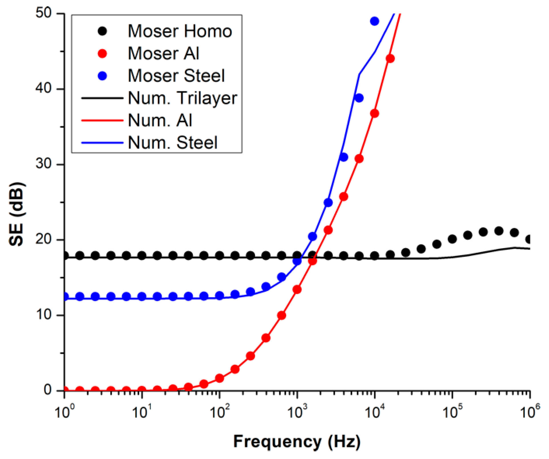
3.5. Iso-Mass Study
The SE of the trilayer composite is now compared in an iso-mass study to the SE of aluminum (Al) and steel layers. The conductivity is set to 37.74 × 10
6 and 9 × 10
6 S/m for the Al and steel sheets, respectively. The relative permeability of steel is fixed to 200. The mass density of the trilayer composite, the Al, and steel layers are 2.55, 2.71, and 7.85 g/cm
3, respectively. Then, the thickness of Al and steel corresponding to an equal mass is 1.974 mm and 652 μm, respectively. The SE of each studied material, calculated in the near-field, is plotted in
Figure 11.
The SE calculated with the Moser model and numerically are close for both Al and steel layers. As the steel is magnetic, a slight difference, less than 0.3 dB, is observed at a low frequency (<100 Hz). Due to their high conductivity, the SE of Al and steel layers increase quickly with the frequency. However, the trilayer composite has a higher SE until 1 kHz. Furthermore, its SE is always superior to 17 dB for the whole studied frequency range. In comparison, the SE of Al and steel layers exceeds 17 dB from around 1.5 and 1 kHz, respectively.
In the far-field, Al and steel layers are expected to show greater SE than the trilayer composite due to their higher conductivities.


 ,
, 


