1. Introduction
Internet of Things (IoT) has been emerging as the third most innovative wave in the information, communication, and technology (ICT) field, after the Internet and computer. However, some collaborative technologies are co-existing, such as radio frequency identification (RFID), to assist IoT for realizing low-cost item-level or things-level inexpensive tagging or sensing [
1,
2,
3]. The UHF RFID systems are most prevalent due to their low-cost inkjet printable tags, fast reading, and sensing capabilities [
4,
5,
6,
7,
8,
9,
10]. Compared with the traditional far-field UHF RFID systems, the near-field UHF RFID system is more suitable for item-level tagging [
11]. Similarly, the near-field UHF RFID systems are very useful in application scenarios where confined interrogation volume is required. Previously, most of the research work was done on flux-type UHF near-field systems, which are quite similar to the HF RFID system. In these designs, the in-phase current loop is used as the reader antenna to produce a uniform magnetic field in the normal plane, and the electrically small ring was adopted as the tag antenna to receive the magnetic energy [
12,
13,
14].
For practical application, the near-field RFID systems usually require a read distance of about 0–10 cm. As we know, the RFID chip activation determines the reading distance of the whole RFID system. In previous researches, most of them use the commercial button tag as a test label to prove the uniformity of magnetic field in normal determined height. However, the electric-small antenna’s energy reception capability is limited by its size, so if we want to achieve an expected height, the transmitting power of the reader antenna should be enhanced. Unfortunately, the in-phase current loop also has an about 2 dBi omnidirectional gain in the azimuth plane. In the case of high transmitting power usage, it is very easy to read other distant tags, which are unwilling for most of the practical application scenarios. So, the tag’s energy reception capability should be enhanced. It is worth noting that just increasing the radius of the tag’s antenna is not a good way because, when the radius of the antenna increases, the uniformity of the electric-small ring’s current and magnetic field will be changed. Moreover, the near-field UHF RFID tag antennas [
15,
16] get very little attention compared with the reader antenna. Therefore, the design of a near-field tag antenna with uniform magnetic field characteristics, simple structure, and 100% reading rate is still challenging for many practical applications.
A quadruple loop near-field reader antenna with uniform magnetic field performance was designed in [
17]. This quadruple design consists of fan-shaped loops, feeding lines, and vias for connecting feed lines to those loops. The quadruple tag design achieved uniform magnetic field distribution by opposite direction current cancellation effects. However, this tag design is costly and difficult to fabricate due to the intervention of vias. Moreover, this tag design is fabricated on a 0.8 mm FR4 substrate. In order to overcome previously mentioned drawbacks, and by attaining motivation from [
18], we know that a non-closed ring can also be excited by the normal magnetic field (H
z).
In addition to Electromagnetic (EM) techniques and solvers, the use of optimization techniques and algorithms are becoming prevalent both in the EM field and antenna design applications. There are several of algorithms used for antenna and RFID tag optimizations such as PSO, Artificial Bee Colony Optimization, and so forth [
19,
20,
21,
22,
23,
24]. PSO is one of the best mainstream algorithms used for the optimization of antennas and RFID tags. PSO algorithm mimics the behavior of swarm of flying bees. Recently, PSO has been employed in a wide variety of electromagnetic structures and antennas. In Reference [
23], a hybrid PSO algorithm was proposed for bandwidth improvement of inverted F (IFA) antenna. Similarly, PSO was employed for gain enhancement of RFID reader antenna [
25], and the planning of a RFID-network by identifying mutual interference and mutual coverage of read-zones among the readers [
26].
Therefore, in this paper, a novel inkjet-printed logarithmic spiral UHF RFID near-field tag, based on TCM and PSO, is presented. The benefit of the logarithmic spiral structure lies in its inherited uniform and large magnetic field receiving area that can be extended to achieve a higher reading distance. TCM can define the potential radiation capacity of a conductor with inherent structure along with near and far-field characteristics. Since the antennas’ receiving and transmitting characteristics are reciprocal, the PSO is used to optimize the antenna structure to have a uniform magnetic field in the normal phase plane. After the radiation structure is determined, a T-match matching circuit is used to meet the conjugate match with RFID chip impedance [
27]. The performance of the proposed design was tested by adopting the same chip as used by the commercial tag (J41). Moreover, to get a robust comparison, the same reader antenna was used for tag reading by previously published researches [
12].
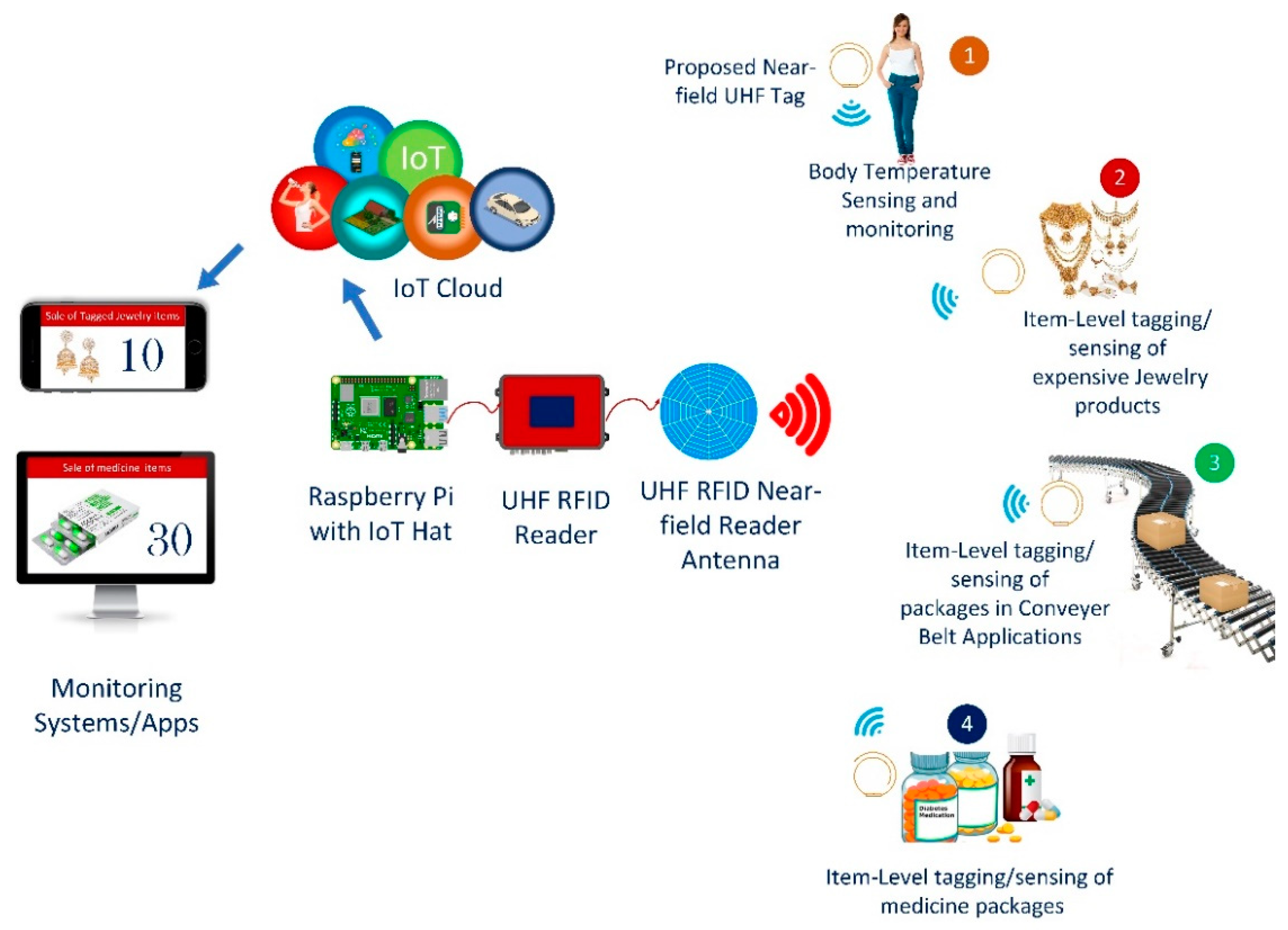
The proposed tag can be readable from very close proximity. It achieves three times more read distance as compared to frequently-used commercial near field tag (Impinj J41) with 10 dBm transmission power, thereby greatly reducing the pressure on reader antenna designers. The proposed tag design is used to demonstrate tagging applications, such as item-level tagging of jewelry items, as shown in
Figure 1. Furthermore, since the tag reading mechanism is based on magnetic field characteristics thereby, it can be used in many sensing and tagging applications [
27,
28,
29,
30] in collaboration with IoT technology, as shown in
Figure 1. For IoT technology assistance, a raspberry pi based setup with LoRa IoT Chip HAT was utilized to connect the RFID reader. The LoRa device provides the connectivity using the LoRa gateway, which helps to store data on the IoT cloud. The data from the IoT cloud can be retrieved for illustration purposes using Web Apps.
The paper is organized as follows:
Section 2 briefly explains the design principle and antenna configuration.
Section 3 demonstrates the antenna optimization process using PSO.
Section 4 elaborates the results and discusses several performance metrics, such as the read range of the proposed tag design. Moreover, it also discusses jewelry item-level tagging and reading experimental setup using proposed near-field tag design. Finally, conclusions are presented in
Section 5.
2. Design Principle and Antenna Configuration
In the HF RFID systems, the read distance relates to the size of the tag’s coil, which means the bigger size of the tag’s coil, the higher the read distance. Whereas, in the UHF RFID systems, just the electrically small loop can meet this condition due to its small wavelength features. Additionally, if the size of the UHF loop tag is increased, the non-uniform and opposite currents will tend to appear.
As mentioned earlier, due to reciprocity property of antennas, the field generated by the same antenna as the receiver is consistent with that generated by the transmitter. If the field distribution of the receiving antenna is consistent with that of the transmitting antenna, the receiving antenna can extract more energy from the field. The higher the consistency between transmitting and receive antennas, the higher the energy captured by the receiving antenna. It is quite similar to the fact that, when the polarization mismatch between transmitting and receiving antennas will be minimum, the associated energy transfer will be maximum.
Therefore, the structure UHF band near-field tag is not necessarily a closed-loop structure, as long as its near-field magnetic field distribution is consistent with the magnetic field distribution generated by the transmitting coil in space. More precisely, if the field distribution of the mode near-field magnetic field, obtained by the characteristic mode theory analysis, is consistent with the field distribution of the magnetic field in space, the structure has the potential ability to receive energy from the field distribution of the magnetic field.
By TCM theory, we can get physical insight into a metal object’s radiation pattern and near field without any external feed excitation. So, we can search for a suitable structure that meets the requirement by analyzing its characteristic field.
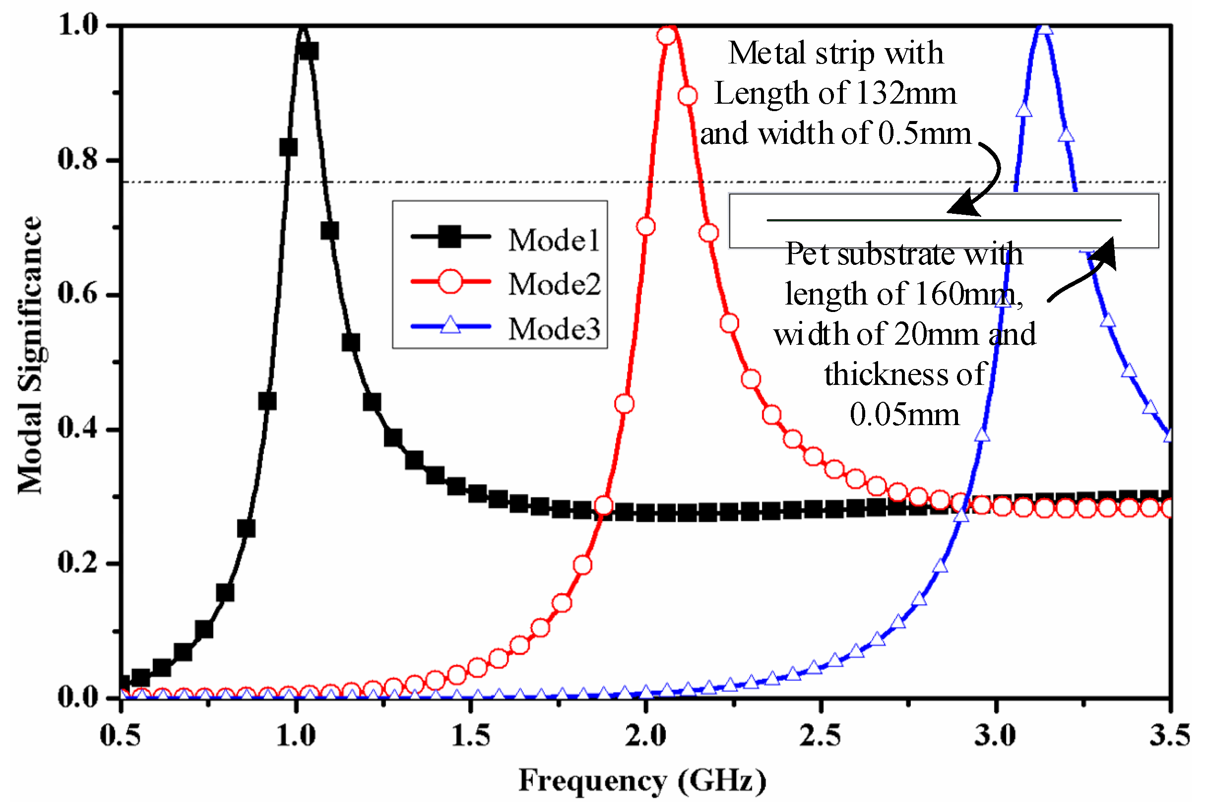
Figure 2 shows the modal Significance (MS) values of the first three characteristic modes of the metal strip (the length of metal strip is chosen as half-wavelength of 915 MHz), characteristic current distribution, and the characteristic near magnetic field associated with these modes (the relative dielectric constant of PET material is 4).
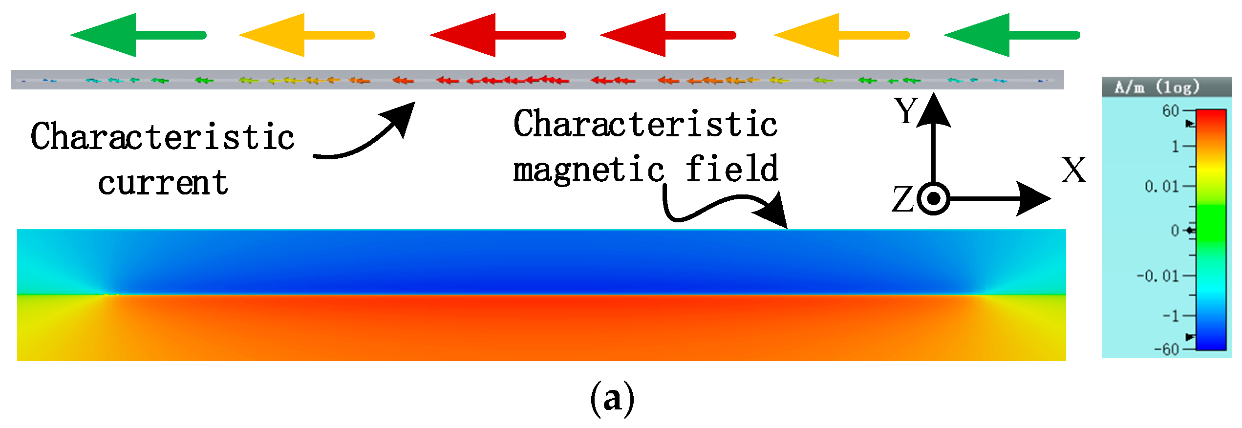
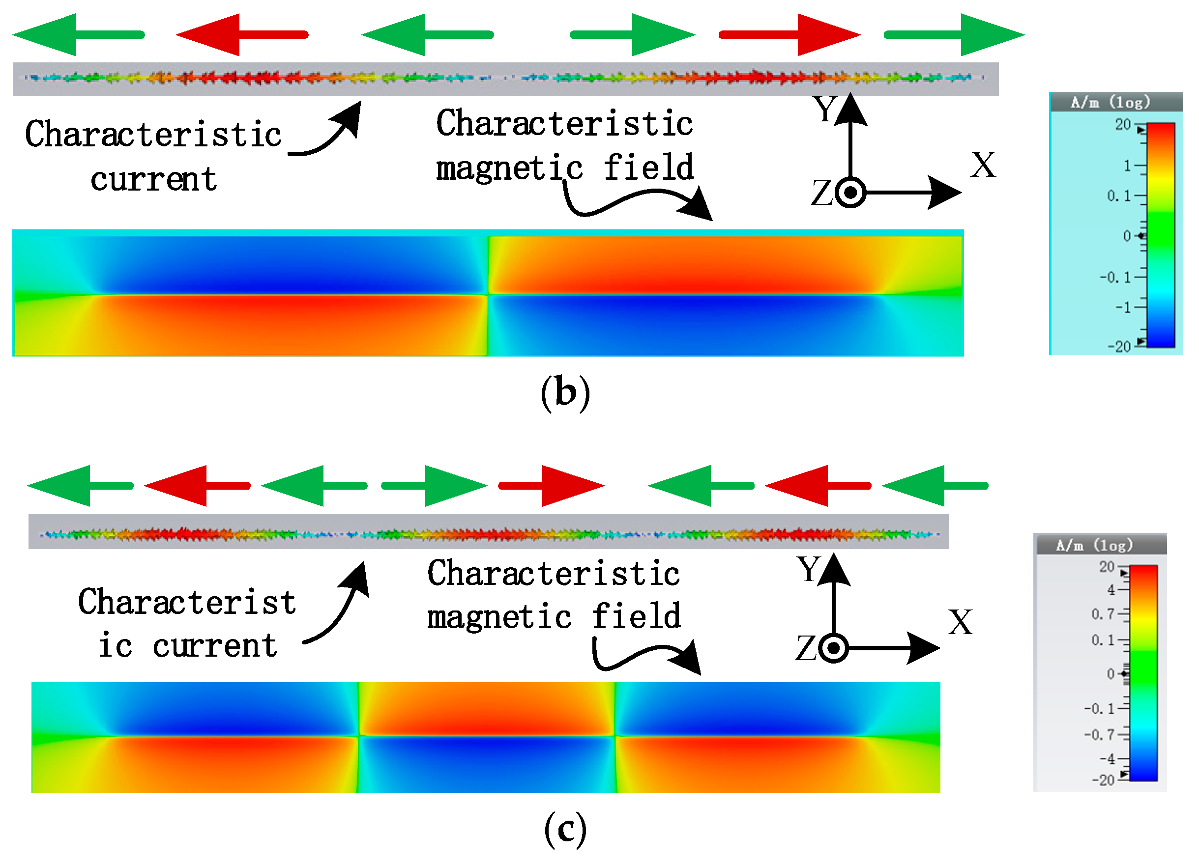
Figure 3a–c show the vector distribution of the characteristic current corresponding to the maximum MS value of mode 1 to mode 3 and the corresponding Z component (H
z) of the characteristic magnetic field at Z = 1 mm (the positive value is taken in the +Z direction and the negative value is taken in the -Z direction). It is worth to mention here that the strip is placed in xy-plane. The characteristic current of mode 1 shows a similarity with the half-wave mode (associated to 915 MHz) current of a dipole. Moreover, mode 1 exhibits open characteristic magnetic field distribution, and its normal component has symmetrical distribution about metal strip structure in Z = 1 mm plane.
The characteristic current of mode 2 is the full-wave mode current of the dipole, and its characteristic magnetic field is also open distribution. In the plane (Z = 1 mm), the magnetic field is symmetrically distributed around the metal strip structure. Additionally, the magnetic field value is also symmetrical concerning the long side of the metal strip. The characteristic current of mode 3 shows that the mode current of 1.5 times the wavelength of the dipole. In the plane of Z = 1 mm, the magnetic field lies on both sides along the length of the strip with the same mode value, and opposite direction. Considering the UHF band RFID magnetic field coupled antenna system, the normal distribution of the magnetic field generated by the reader antenna is uniform and in phase in its normal plane. In contrast, the Z component of the magnetic field (near-field) around the three modes of the metal strip has the same mode value with opposite direction, indicating that the metal strip antenna cannot obtain energy from the magnetic field generated by the reader antenna.
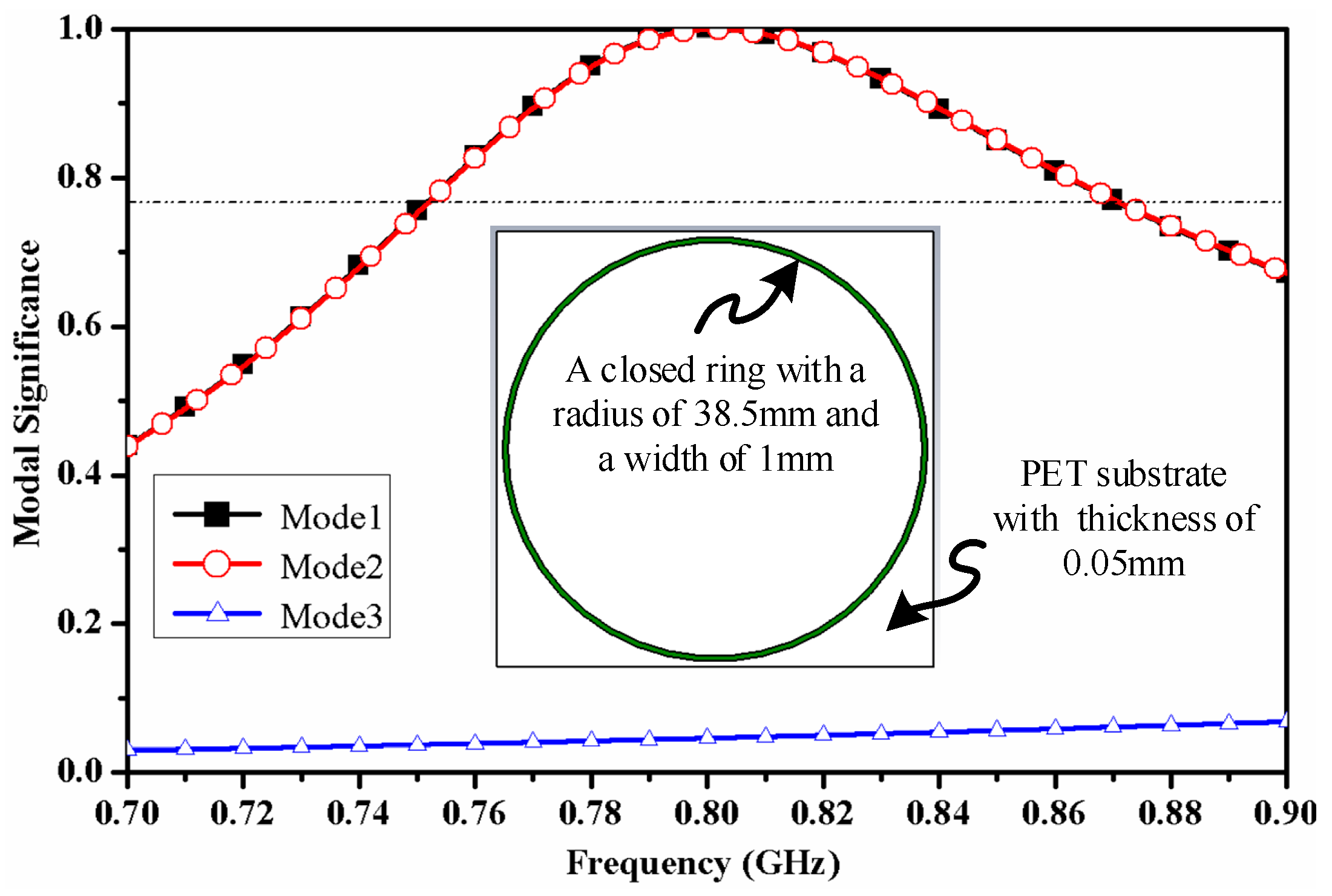
Figure 4 shows the MS values of the first three characteristic modes of the closed-loop, the distribution of the characteristic current and the magnetic field characteristics (the relative dielectric constant of PET material is 4).
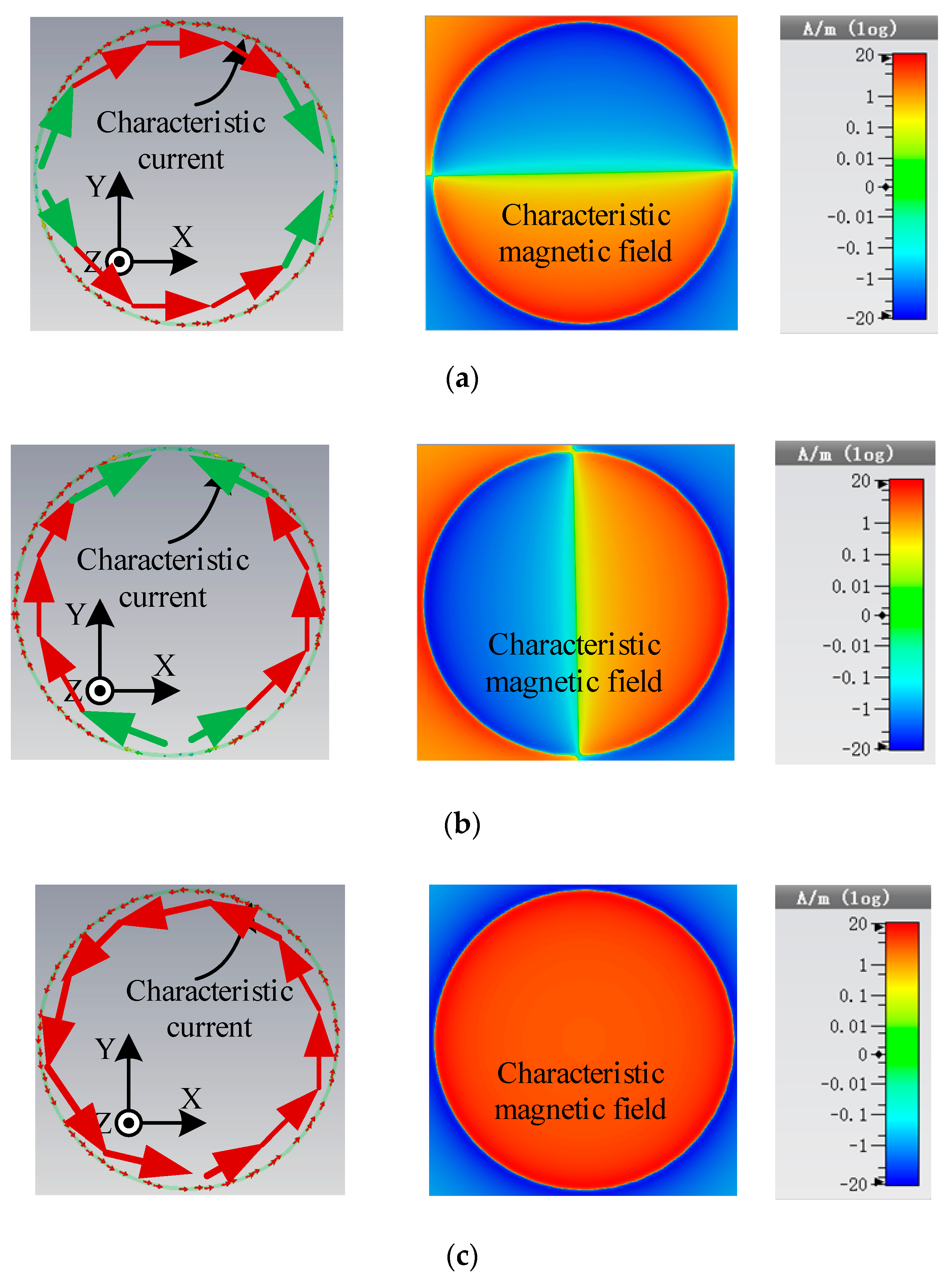
Figure 5a–c show the vector distribution of characteristic current at 800 MHz and Z component of the characteristic magnetic field at z = 1 mm for mode 1 to mode 3. The MS values of mode 1 and mode 2 of the closed metal ring reach the maximum at 800 MHz, and it can be seen from the current distribution that mode 1 and mode 2 are a pair of degenerate modes. It can be seen from
Figure 5a,b that the magnetic field distribution of mode 1 and mode 2 in the closed metal ring is symmetrical about a midline, with the same amplitude and opposite direction. Therefore, the total magnetic flux in the closed metal ring is zero, since the two modes cannot obtain energy from the uniformly distributed normal magnetic field. Looking at
Figure 5c, the current flow direction in mode 3 is not reversed, and the values are equal. Therefore, the magnetic field distribution in the closed-loop is in phase, and the corresponding magnetic field on concentric circles is the same. Considering that, in the UHF band RFID magnetic field coupled antenna system, the magnetic field distribution generated by the reader antenna is uniform and in phase in its normal plane. If only focusing on the field distribution, mode 3 can obtain energy from the magnetic field generated by the transmitting coil. However, the MS value corresponding to mode 3 is very small in the whole frequency band. If the excitation is introduced, the current flow direction cannot be reversed in the small electric size. Therefore, for the closed ring structure, it is not possible to expand the size of the closed-loop without changing the current flow direction. Moreover, it is convenient to make a good conjugate matching in such a small size.
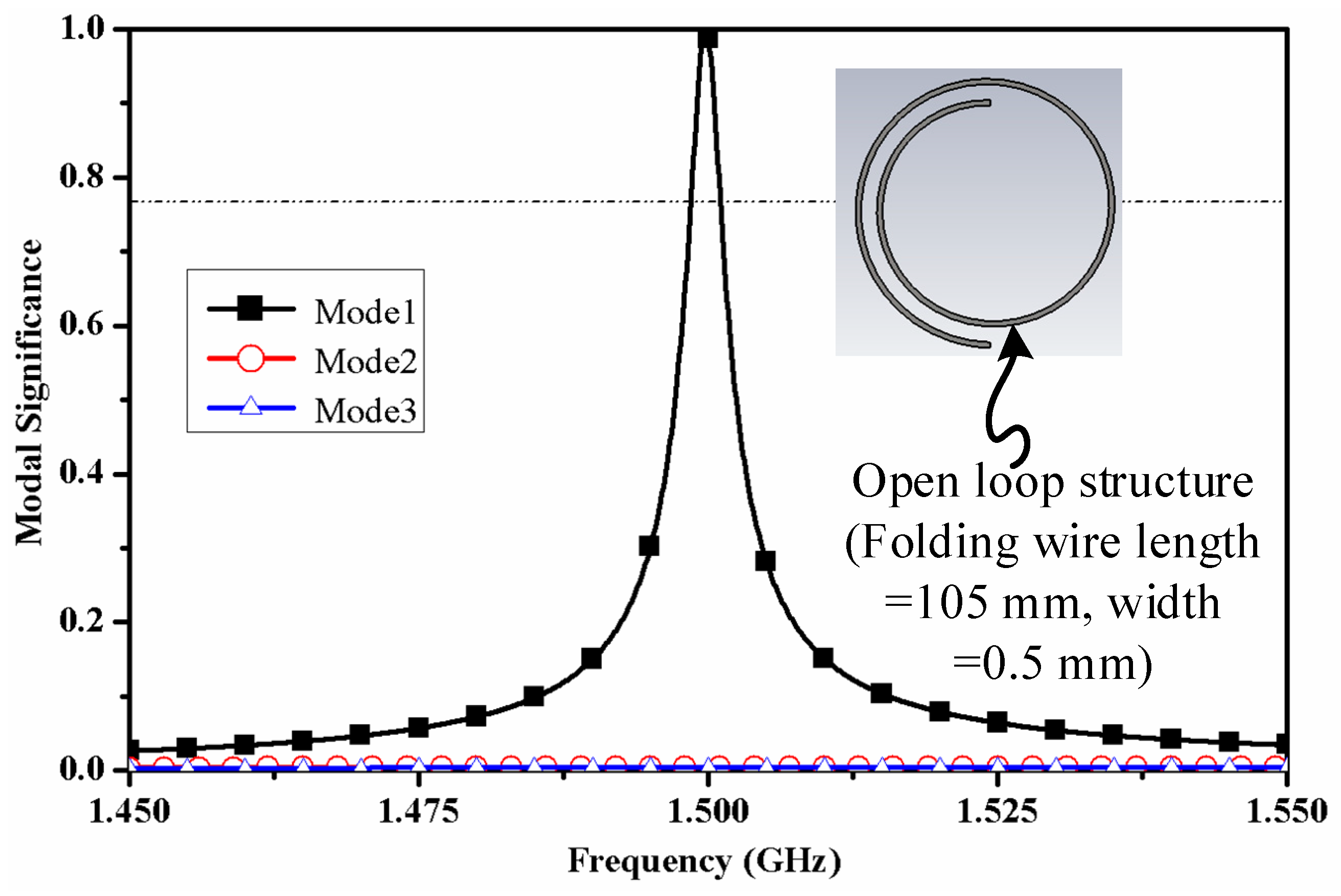
For choosing electrically small structure, we run CMA for open loop structure with overall length of 100 mm. After running some rigorous simulation tests, a structure with 105 mm was selected for demonstrating required performance at 1.5 GHz. The open structure dimensions were taken by folding 105 mm length wire to the center line.
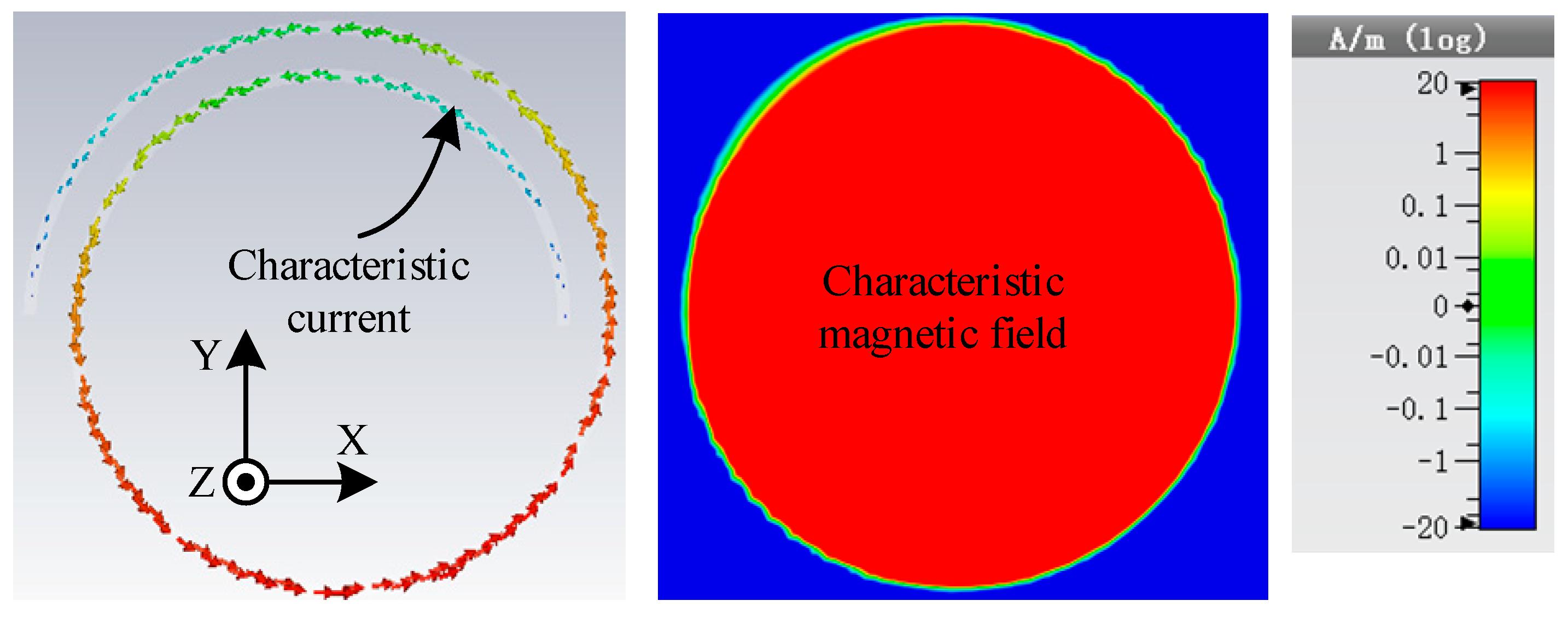
Figure 6 shows the MS values of the first characteristic mode of the open-loop structure. The proposed open-loop structure shows a peak MS performance at 1.5 GHz. Similarly,
Figure 7 shows the distribution of the characteristic current and associated characteristic magnetic field (the relative dielectric constant of PET material is 4). In mode 1, MS reaches the maximum at 1.5 GHz. By observing the characteristic magnetic field distribution of mode 1, it can be concluded that the near-field magnetic field distribution of this structure is similar to that of mode 3 of the closed-loop. Therefore, the open loop structure has the ability to receive energy from the near-field magnetic field.
3. Tag Antenna Optimization Using PSO
The magnetic field intensity of the tag antenna is related to the current intensity. Therefore, we can optimize the uniformity of the magnetic field by optimizing the superposition of the current at different angles. In order to optimize the uniformity of the current, the PSO algorithm is used. Equation (1) shows the mathematical expression of the logarithmic spiral in polar coordinates. From Equation (1), we can know that three parameters (a, b, and θ
max) can be optimized. However, if the total length (L) of the logarithmic spiral is determined, the relationship between the three parameters will also be determined. Equations (2) and (3) show the relationship between the three parameters and the current expression with the θ as a parameter, respectively. For fitness function (Q), we define a new parameter I
angle = I
θ + I
θ + 2π, noticeably, if the θ + 2π ≥ θ
max, the I
θ + 2π is 0. So, the square difference of the I
angle is the fitness function, which is shown in Equation (4). The I
angle,I represents the current value in the 4th point. The parameter n indicates the division accuracy from 0 to 2π.
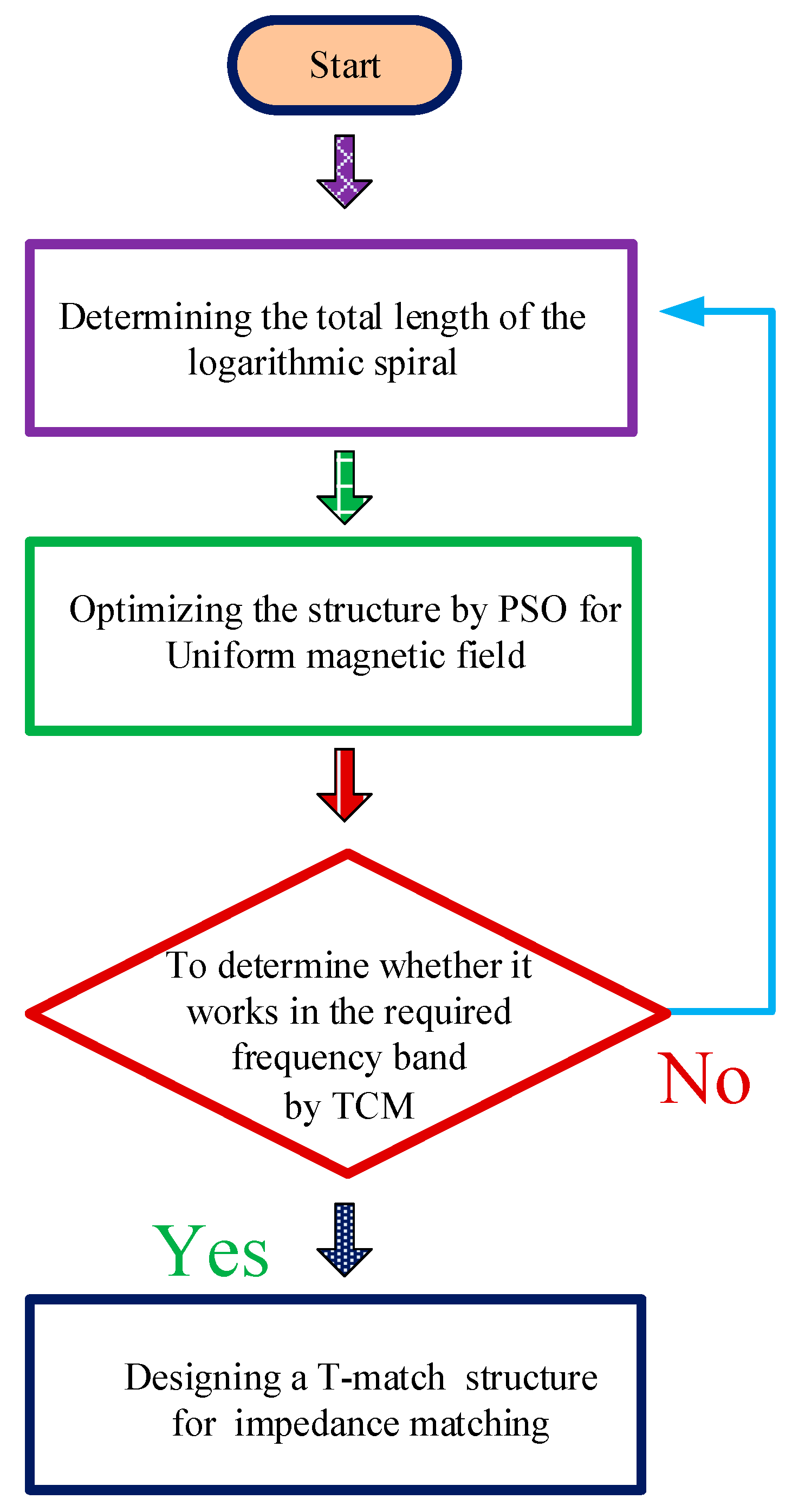
Figure 8 shows the flowchart of the proposed design methodology. In the first step, we give the overall length of the logarithmic spiral, and the PSO algorithm was utilized to define the structure for the uniform magnetic field in the normal plane. The PSO algorithm was implemented in MATLAB for achieving optimal tag design parameters to achieve uniform magnetic field performance.
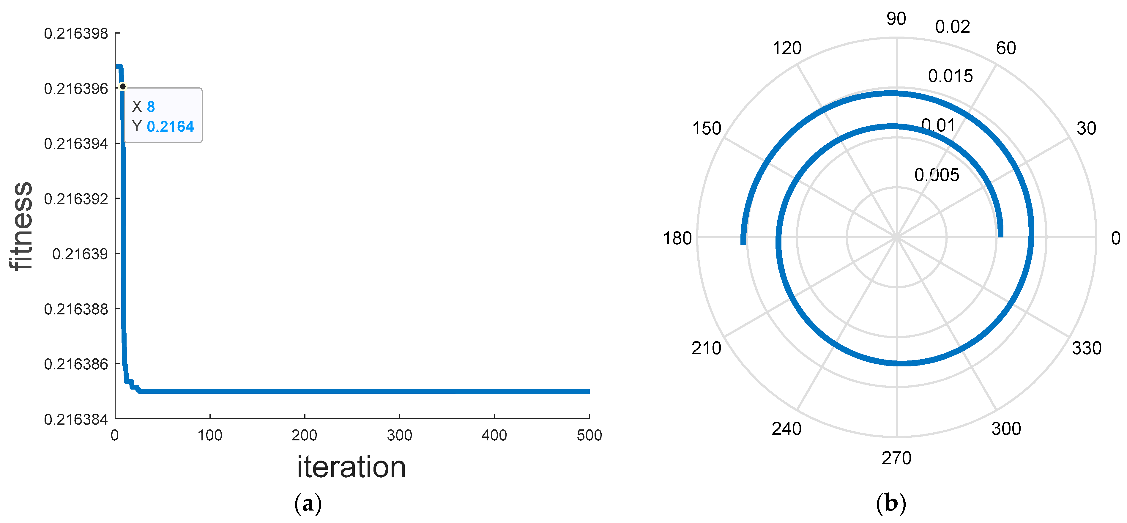
Figure 9a,b illustrates the fitness Curve of PSO-based optimization for the proposed near-field tag and the optimized tag parameters achieved after implementing the PSO algorithm in MATLAB, respectively. The optimal tag parameters achieved using the PSO algorithm was utilized further to construct the tag structure in CST Microwave Studio 2018.
In the second step, the structure using these parameters was calculated by TCM theory to determine whether it has reception capability in the required frequency band. After finalizing the design resulted from TCM, a T-match matching structure was designed, at the maxima of characteristic current, to meet the conjugate match with RFID chip impedance. In case, if design resulted from TCM does meet the requirement, we need to change the overall length and repeat the first step.
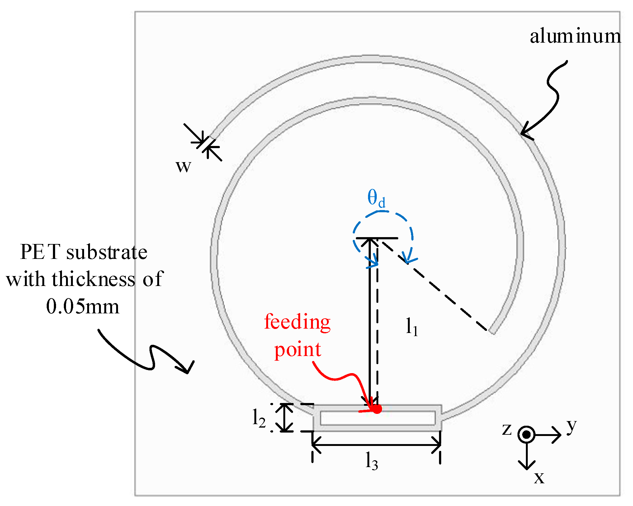
Figure 10 shows the structure of the proposed antenna, which consists of a logarithmic spiral and T-match structure.
Table 1 gives the detailed parameters of the proposed design. To compare the performance, we chose the same antenna material, substrate, and chip (Monza 4 QT with impedance 11-j143 Ω) as the commercial tag. The substrate is PET material (relative permittivity is about 4) with a thickness of 0.05 mm. The antenna was printed using aluminum ink. The width of every line in this structure is 0.5 mm. As mentioned above, the excitation should place at the maximum of the characteristic current point, which can be estimated as θ = θ
d. For the T-match matching structure, it should be flat to avoid influencing the characteristic mode of the logarithmic spiral.
4. Results and Discussion
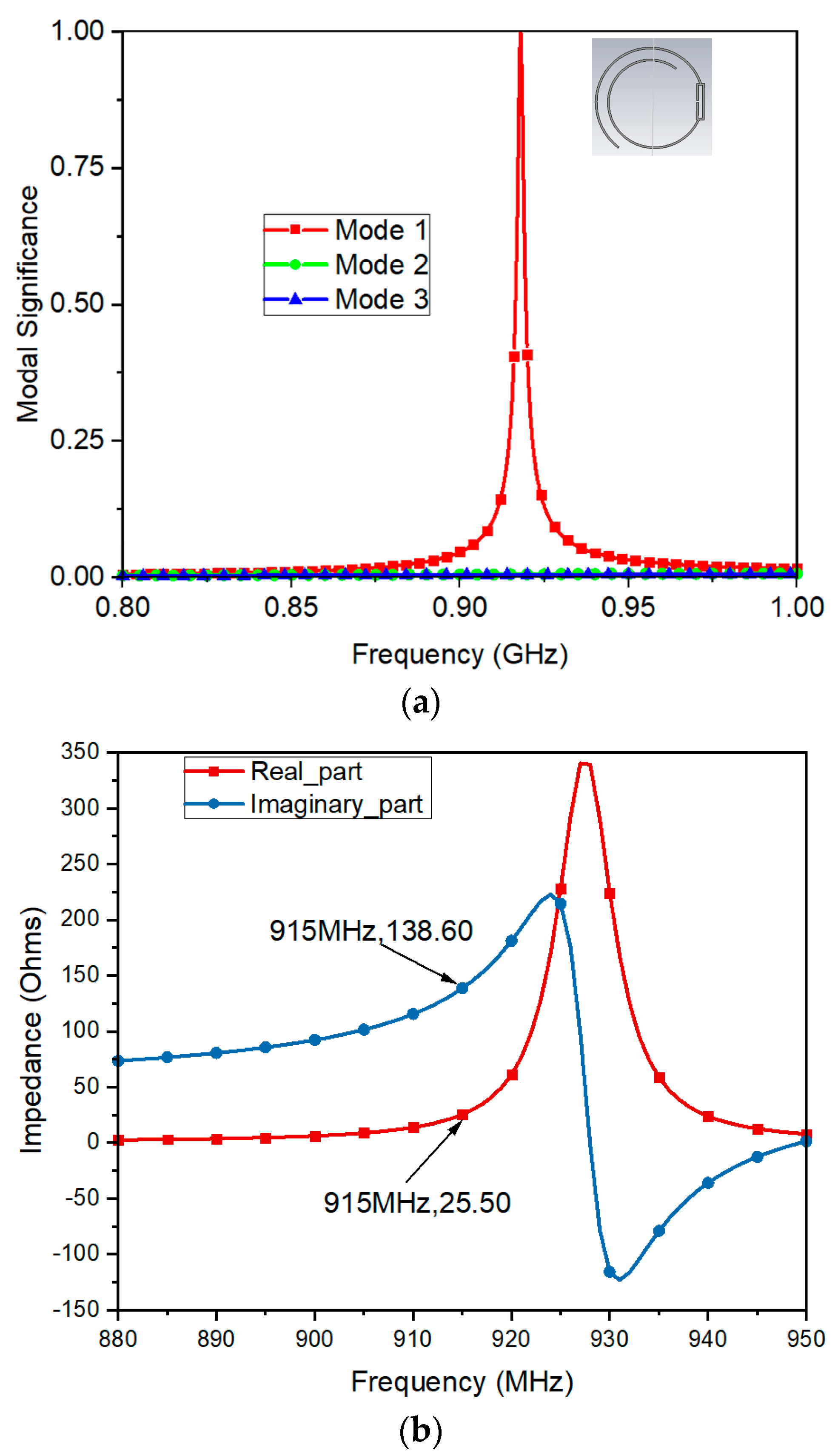
Figure 11a shows the MS of proposed open loop structure that shows superior performance of mode 1 in term of significant mode and radiation capacity. The real and imaginary part of impedance associated with the proposed tag antenna is shown in
Figure 11b. This tag design shows a good impedance match with the Impinj Monza 4 QT RFID chip with approximate impedance 11-j143 Ω.
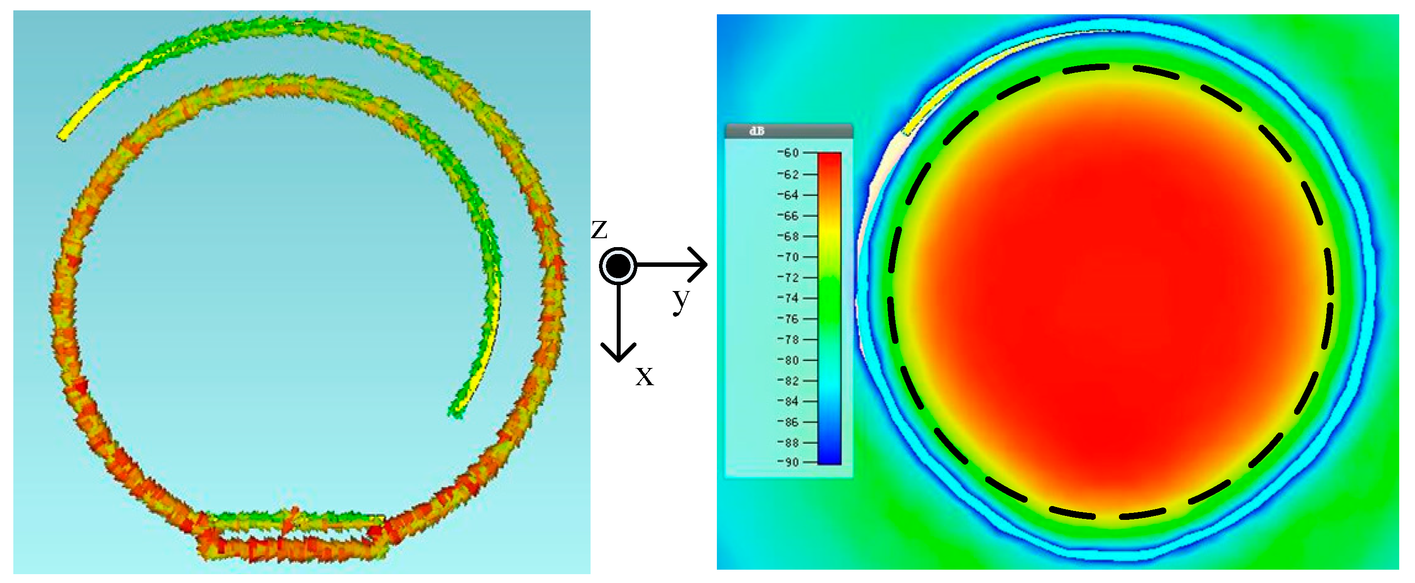
Figure 12 shows the current distribution and magnetic field (H
z) in the normal plane with height (h = 5 mm) at 915 MHz. The current distribution shows, the current remains in phase through the whole tag structure that further leads to the uniform magnetic field in an area equal to the size of the tag. A full-wave electromagnetic simulation has been carried out by means of the commercial software CST Microwave Studio Suite 2018 to prove the performance in terms of current, and magnetic field (H
z). To verify the performance of the proposed tag further, a prototype of the proposed tag, along with some other and commercial tags, was fabricated to compare their performance.
The tag antenna was fabricated using silver nanoparticle paste from Harima NPS series and Fujifilm Dimatix DMP-2831 inkjet printer with a 10 pL volume cartridge. Moreover, the tag was fabricated on 50 µm PET substrate with 4 layered printing approach.
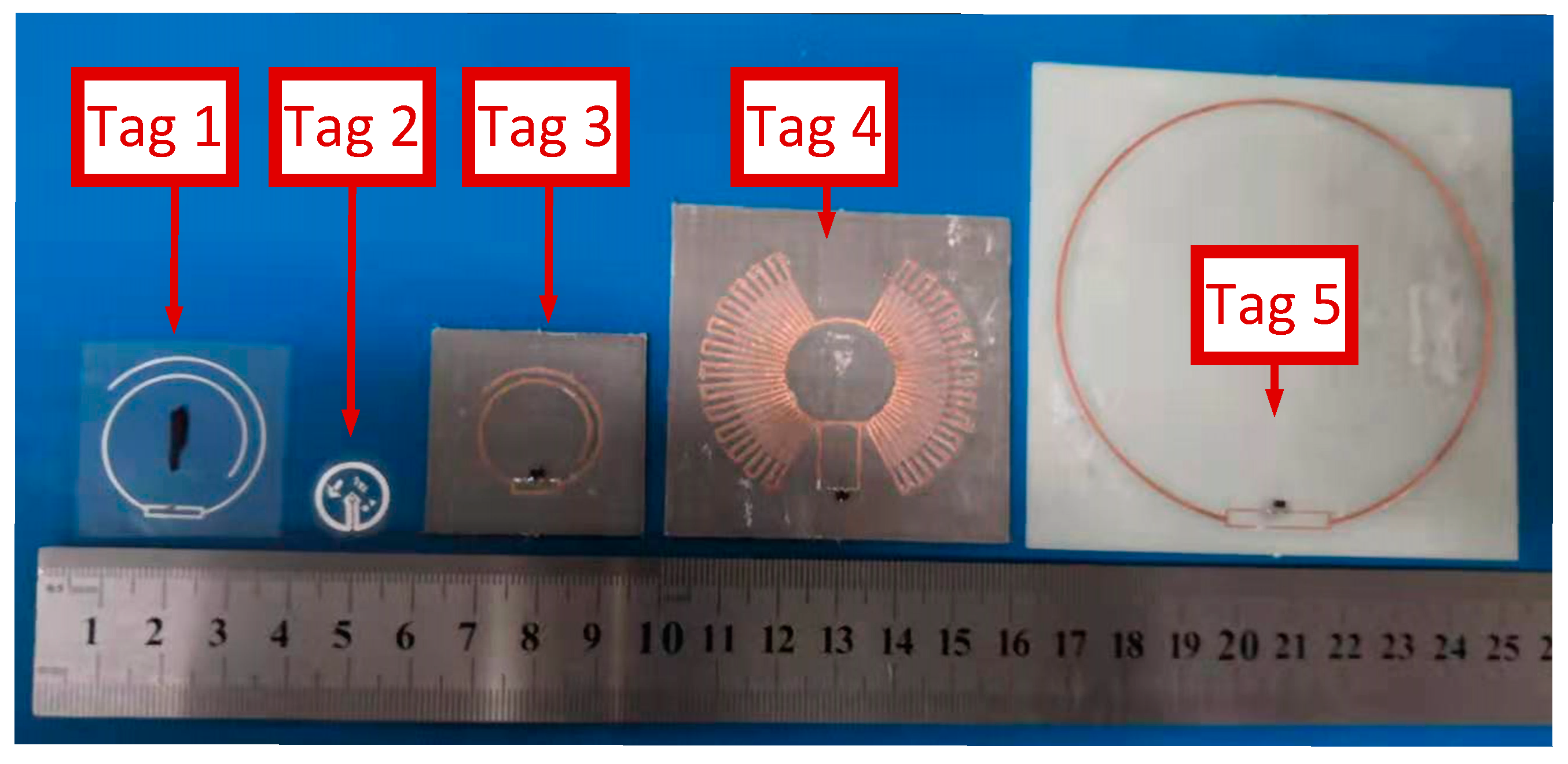
Figure 13 shows five tested tags, which are numbered as tag1 to tag5. Tag1 is our proposed tag, and tag2 is the commercial button tag, which has the electric-small loop. The tag3, tag4, and tag5 are printed in the PCB substrate, and the chips of them are all H4 SOT packaging. Tag3 is based on the same theory as the proposed tag in this paper. The antenna of tag4 and tag5 are both full-wavelength loops, and tag4 is the miniaturization of tag5. A near-field antenna in the published paper is used as the reader antenna [
5] to test the performance of the five tags.
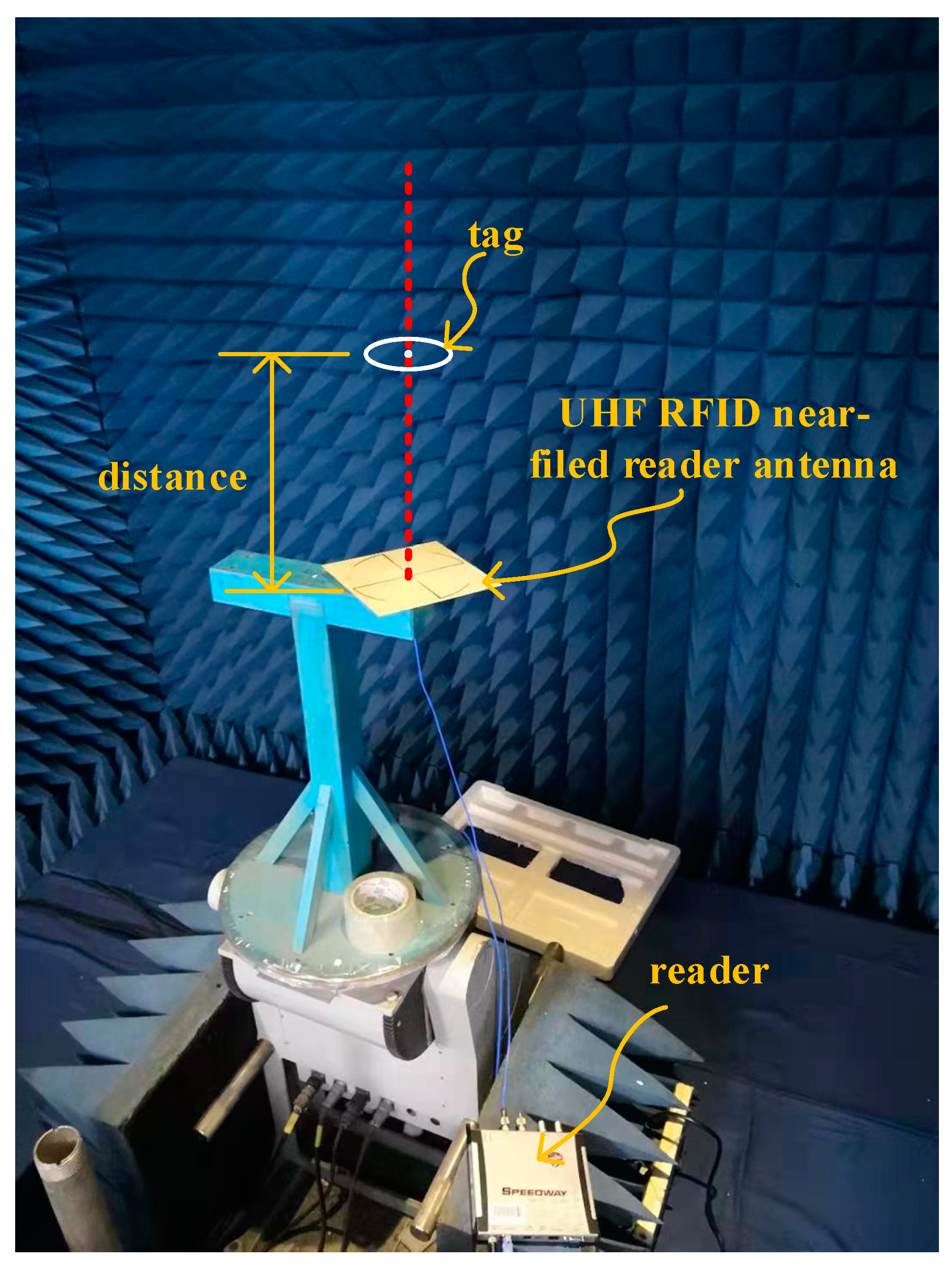
Figure 14 shows the test environment, which is a semi-open microwave anechoic chamber. The setup was explored using different transmit power levels for testing read range and further specifying the integration zone. The maximum read distance, which is tested by the center to center of the tested tag and the reader antenna is recorded in
Table 2.
From
Table 2, tag4 and tag5 have the biggest size in all tags, but they are hardly readable, which means it is not the bigger size, the more read distance for the closed-loop antenna. Tag1 has three times more read distance as compared to tag2, which means that a closed structure is not always necessary for receiving near field energy in the case of the UHF band. Furthermore, the proposed tag opened structure can provide both the flexibility of extending the receiving area as well as adjust the uniformity of the magnetic field, which is more suitable in this circumstance. Because of the differences in sensitivity (the sensitivity of Monza QT is −17.4 dBm and the H4 SOT is −20.5 dBm), the read distance of tag3 is more than tag1. The test results validate our proposed design very well.
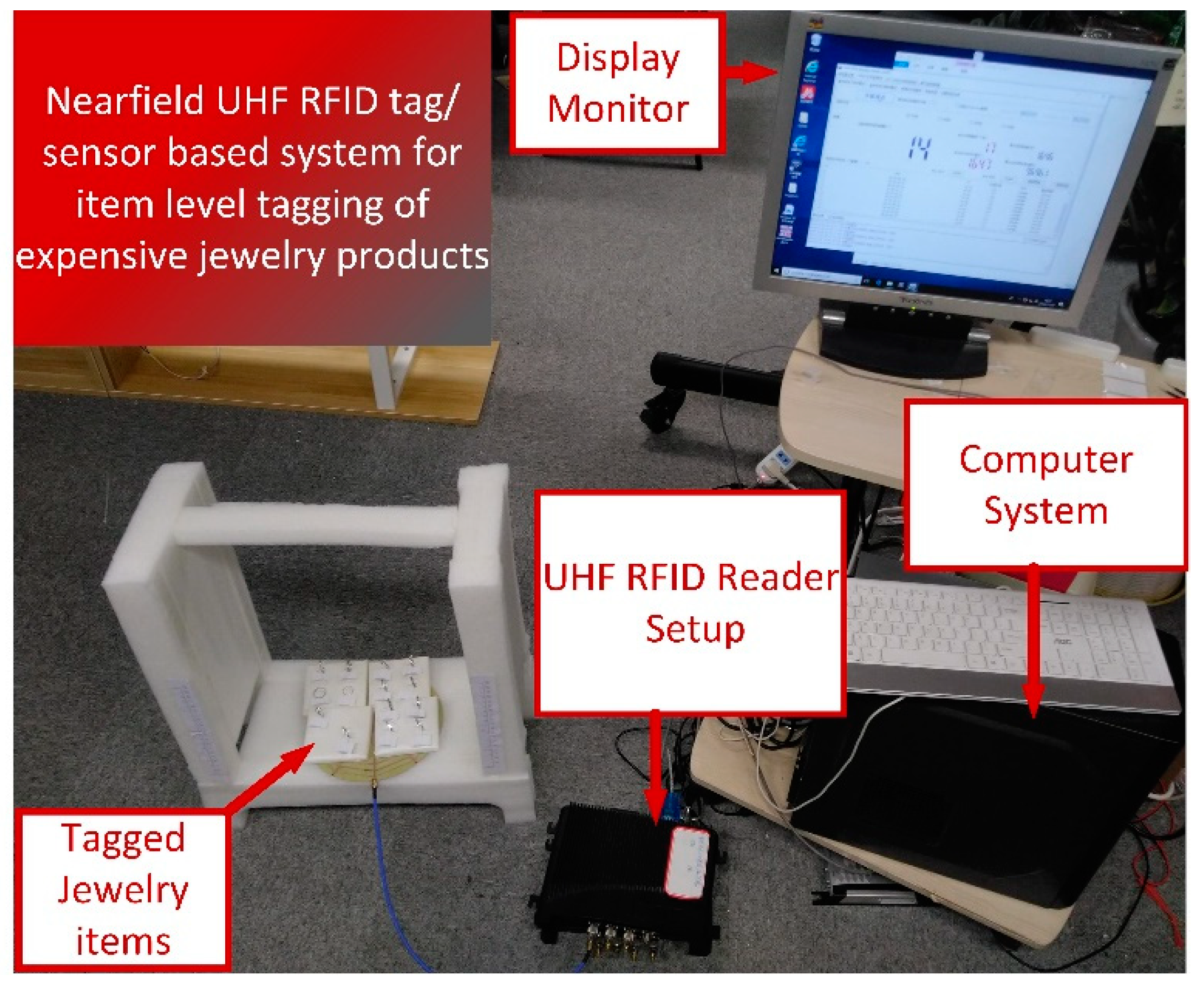
Finally, the proposed tag antenna was used experimentally for item-level tagging of jewelry products, as shown in
Figure 15. The setup consisted of a foam-based frame, near-field reader antenna, RFID reader, and tagged jewelry products. The proposed tag/sensor exhibited 100% reading accuracy up to 46 cm with transmit power of 30 dBm. In addition to this, the proposed tag antenna can be exploited for temperature sensing of the human body as its main working principle is based on the magnetic field that is significantly less affected by permittivity changes.


 ,
, 


