1. Introduction
Power integration lowering both masses and volumes of powertrain devices embedded in transport applications is actually a great challenge for researchers, especially for actuation systems [
1]. In ground transportation, numerous studies are focused on optimization strategies for power integration, such as in the review proposed in [
2] for hybrid electric vehicles. If these challenges are huge for ground vehicles, reducing embedded weights in more electric aircrafts is a key driver for aeronautic evolution, as reviewed for example in [
3]. It is especially true that typical “snowball effects” occur in aircrafts: the more embedded weight, the higher the wing surface and the more fuel burn. For example, [
4] has shown that one additional ton would increase the fuel burn by 6% in the case of a regional aircraft. The ACARE (Advisory Councilor Aviation Research and Innovation in Europe) sets environmental objectives for 2050 technologies with a 75% reduction in CO
2 emissions per passenger kilometer and a 90% reduction in NOx emissions. The perceived noise emission of flying aircrafts should be reduced by 65%. These are relative to the capabilities of a typical new aircraft in 2000. More generally, the aviation industry actually faces the “revolution towards more electric aircrafts” [
5,
6,
7,
8].
Superconducting technologies in machines and power electronics may bring significant efficiency and weight reduction benefits over conventional components [
9], but most of these promising technologies are currently, and for the near future, at a relatively low technology readiness level. Thus, conventional technologies are often preferred for transport applications. Several machine topologies can be selected and compared [
10], especially in the automotive field for hybrid (and/or electric) applications [
11,
12]; in the automotive field, high specific power machines are embedded, until 4.3 kW/kg for the Tesla S60 rotating at 15,000 rpm [
13,
14]. Indeed, the trend towards high-speed actuation systems clearly exists in transport applications [
15], which tends to reduce weight and volume. In aeronautic applications, the PMSM (permanent magnet synchronous machines) and the IM (induction machines) are the most adequate technologies. In addition to the higher efficiency of the PMSM over the IM, the PMSM also features higher specific torque, and this solution is seen today as the most suitable for weight optimization: this latter device has been selected in our study.
Optimizing the hybrid electric powertrain requires coupling a large set of domains, each involving heterogeneous phenomena and constraints in various physical fields. In that context, MDO (multidisciplinary design optimization) has become a methodological challenge itself, with several approaches and design strategies [
4,
16].
A typical MDO approach is proposed for optimizing the whole powertrain of future hybrid electric aircrafts in [
17]. This study, partly presented in the proposed paper, is one part of a European Project in the framework of the Cleansky II EU project called “HASTECS” for “Hybrid Aircraft: Academic Research on Thermal and Electric Components and Systems.” In HASTECS, several studies [
14,
18,
19,
20,
21] analyze innovative technologies (power electronics and advanced cooling, electric motors and its cooling, high voltage and partial discharges) and concepts for regional hybrid aircraft optimization in the case of a series hybrid architecture beyond 1 MW for power and beyond 1 kV for the bus voltage standard.
In his PHD Thesis, Pettes-Duler, M. [
17] proposes the sizing optimization of the powertrain, integrating both the energy management strategy and the flight mission. This paper focuses on the actuation system including a PMSM, with the actuation weight being targeted as the optimization objective. As proposed in the HASTECS project, electric motors with high specific powers beyond 10 kW/kg are targeted in our optimization, with very high efficiencies (typically 97% at maximum power point). Aggressive targets have been chosen, but certain targets are already achieved in other studies [
22]. In particular, Siemens [
23], with the electric motor SP260D, has announced 5.2 kW/kg for a motor in flight tests. The University of Illinois [
24] has designed a PMSM which would exceed a specific power of 13 kW/kg with an efficiency of 96%, showing that these targets may be reached. General Electric [
25] has announced to reach a specific power beyond 10 kW/kg for a power inverter for Aircraft Hybrid-Electric Propulsion. Several tools can be used to design and optimize electric motors [
26].
In
Section 2, the context of the MDO process is introduced, synthesizing the optimization problem formulation.
The modeling task is one of the key issues for electric machine design: for example, [
27] has recently presented an open-access electric machine design tool using MATLAB
® in order to enable an automated machine design. In our paper, a large set of heterogeneous sizing models are integrated, being strongly simplified in order to allow for solving this huge complex MDO process with acceptable computational times: these models are analytical for the electric motor [
14] and its cooling [
19], or based on parametric regression, as for partial discharge constraints [
21].
One major contribution of this paper is related to the MDO process, especially coupling a large set of multidisciplinary constraints:
Thermal constraints are involved in comparing steady-state and transient thermal behavior. Electro-thermal coupling is integrated into the optimization problem [
28] emphasizing the “first-order influence” on the actuator performance. Several cooling systems can be assessed, as reviewed in [
29].
The actuation system being supplied by a high DC voltage bus, the Electrical Insulation System (EIS) in the PMSM [
21], is also integrated through a simple surrogate model that involves insulation constraints due to partial discharge occurrence in stator slots.
Regarding the bus voltage level and the equivalent impedance of the PMSM, the opportunity of a field-weakening strategy can also be assessed to optimize the performance according to the flight mission sequences. A supplementary constraint related to permanent magnet demagnetization is added for that purpose. This “flight mission-electric circuit-magnetic” coupling also affects the motor design and its specific power.
Several analysis and optimization results are presented in the last two sections: in
Section 4, the huge influence of the transient behavior of the electro-thermal coupling is analyzed. The design choices are discussed, comparing steady-state and transient thermal models over the flight mission. Finally, in
Section 5, the sensitivity of technological progress on actuation performance is analyzed, especially in terms of specific power and efficiency. This last part of the paper shows that the proposed MDO process allows reaching very high integration performance.
2. Context of the MDO Process
A complete design at the aircraft level is particularly complex because of the high number of decision variables with strong interactions between disciplines. A systemic study takes account of all (whenever possible) device couplings, far beyond summing local optimizations at the component level. It is within this framework that MDO is currently working because it allows gathering different fields around a single mathematical problem. Most often, this integrated design method is used to look at the sensitivity of the aircraft design, as well as its aerodynamic performance. For example, [
27] linked the aerodynamic performance with non-linear physical phenomena occurring on the aircraft through an MDO. A robust and operational tool is presented in [
30] in order to couple complex studies and highlight new aircraft concepts. Another optimal industrial trade-off for pylon design results from this: a demonstrator optimization test case has been implemented by the IRT Saint Exupery [
31].
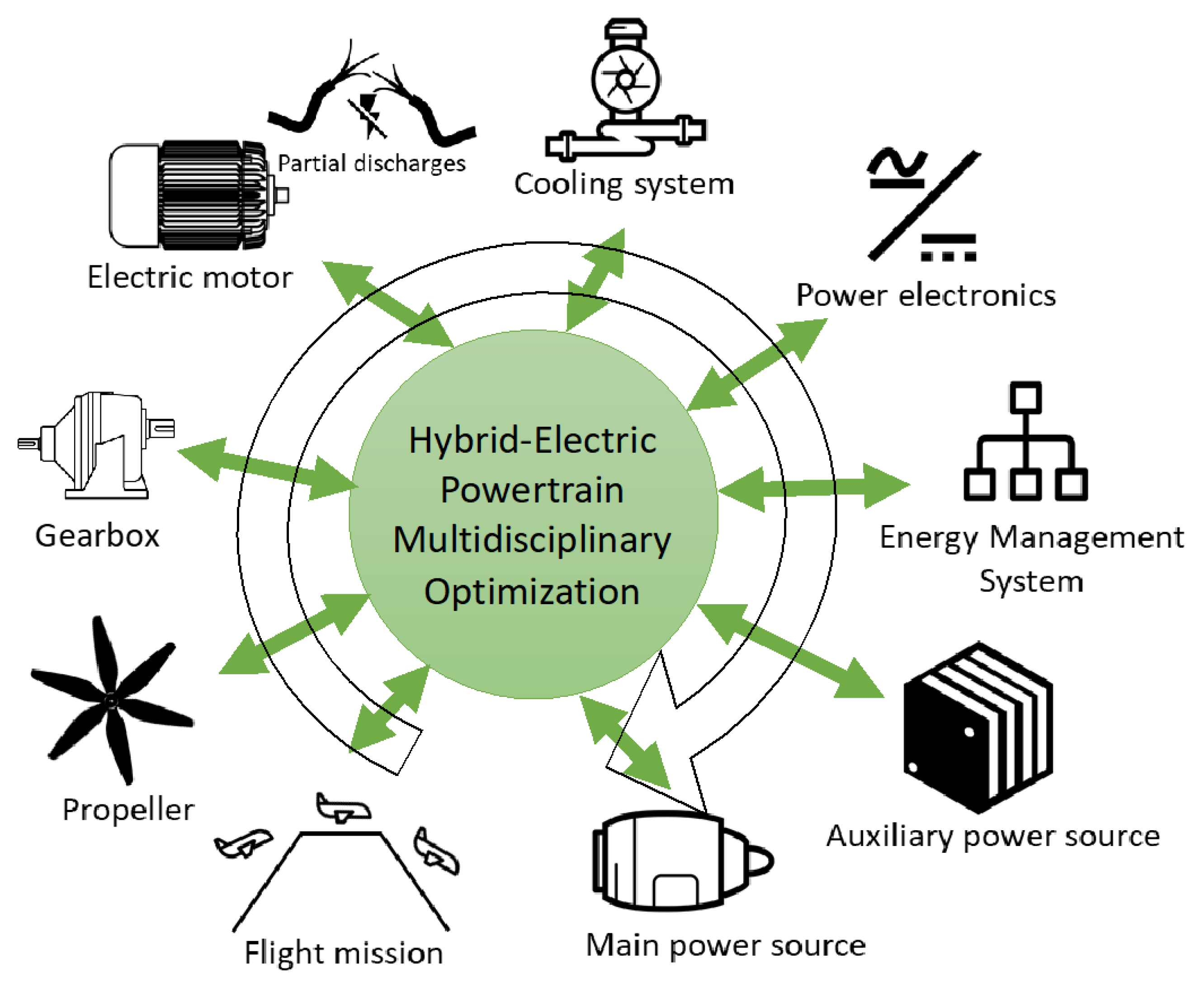
The study presented here is the preliminary step of a more complete MDO process is managed at the powertrain level in the thesis of Pettes-Duler [
17]. This approach is applied to the design of a hybrid electric aircraft for regional flight. The final MDO process involves a large set of multi-physical aspects, as illustrated in
Figure 1.
Before developing the system optimization at the powertrain level, a complete sensitivity analysis has been performed in [
32], showing the major importance of the actuation system, especially the PMSM with regard to the powertrain weight and efficiency.
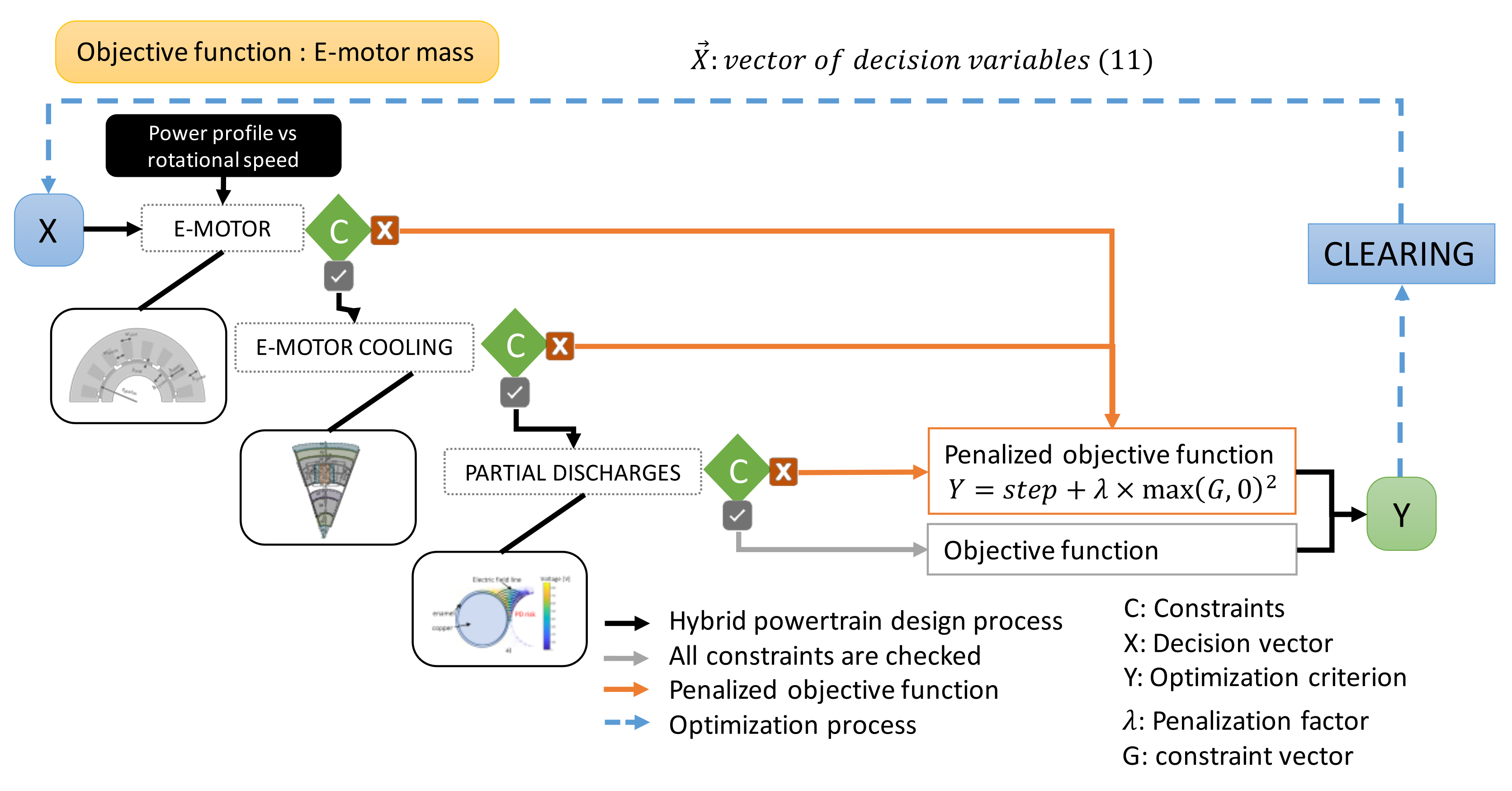
That is why a major preliminary step is to focus on the actuation part optimization, as presented in the next sections. Before presenting the models of the actuation system,
Figure 2 illustrates the optimization formulation aiming at minimizing the electric motor mass.
3. Actuation System Modeling for MDO Process
In this section, we focus on the modeling of the inverter-fed surface-mounted permanent magnet synchronous machine (SM-PMSM) for high-speed applications. The theoretical backgrounds of the SM-PMSM model are based on the modeling of the open-circuit field and the armature reaction by current surface density [
33]. From these theoretical backgrounds, an analytical sizing model based on loadability concepts has been derived [
14,
34] and has been revisited to be integrated in an MDO process. Such model seems to be the most suitable compared to finite element or permeance network models that lead to high computational times. Moreover, this model is dedicated to being further integrated in the whole powertrain optimal design, for which complexity and computation times constitute high challenges to be faced. In that context, the simplicity of analytical models and their short computational times are advantages that facilitate the optimizer’s tasks. In addition, less information is required for the system definition, unlike other models that sometimes require a large amount of input data. However, these models are less accurate compared with finite elements and they require simplification assumptions that are generally valid for a specific operating domain. Therefore, in order to optimize the complexity–validity trade-off, a validation of the analytical model has to be performed. In [
33], the computation of the airgap magnetic flux density, the no-load back-emf and the torque obtained with this model have been validated by a finite element analysis.
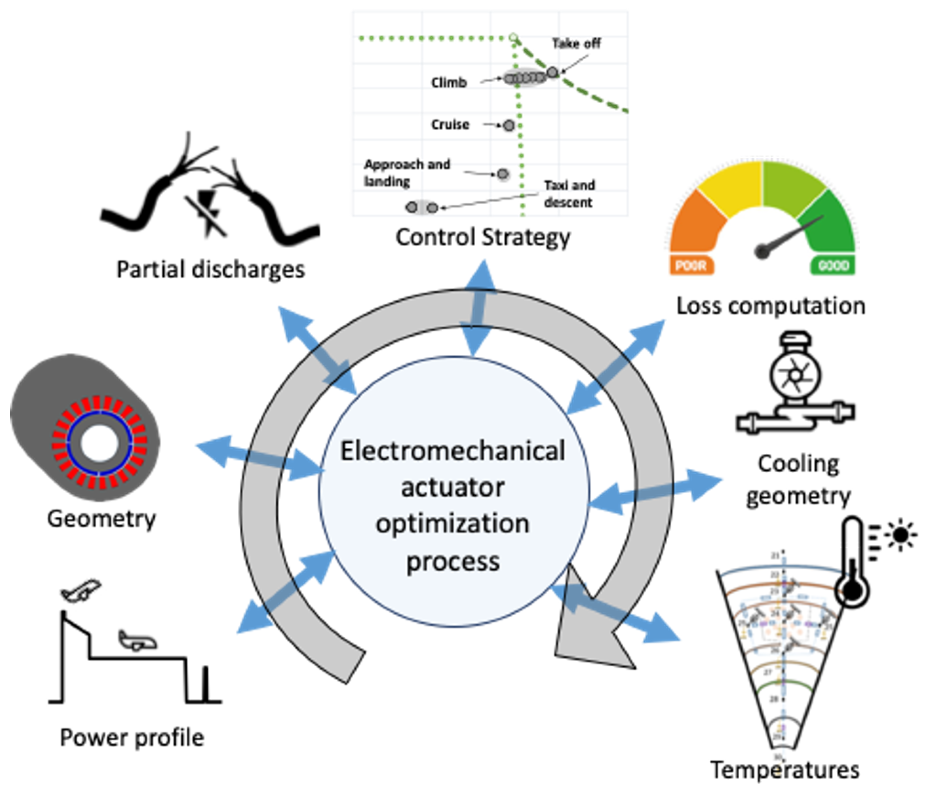
The design model describes all the physical phenomena involved in the operation of the machine. Based on a power profile corresponding to a typical regional flight, and after defining the geometry of the machine, a magnetic model allows calculating most of its dimensions. Then, an electrical model specifies the different electrical circuit parameters of the machine which are required for coupling the motor with its power supply. At this stage, the structure of the machine is fully defined, and its mass and volume are determined. The losses in the different parts of the machine are computed for each operating point of the flight mission, enabling the electro-thermal coupling. Finally, the machine design must satisfy specific requirements in terms of thermal resistance of its various parts and the magnetic state of the magnets. Thus, a thermal model has been integrated taking into account the cooling systems as studied in [
19]. This electrometrical MDO process is illustrated in
Figure 3.
3.1. Geometrical Design Model
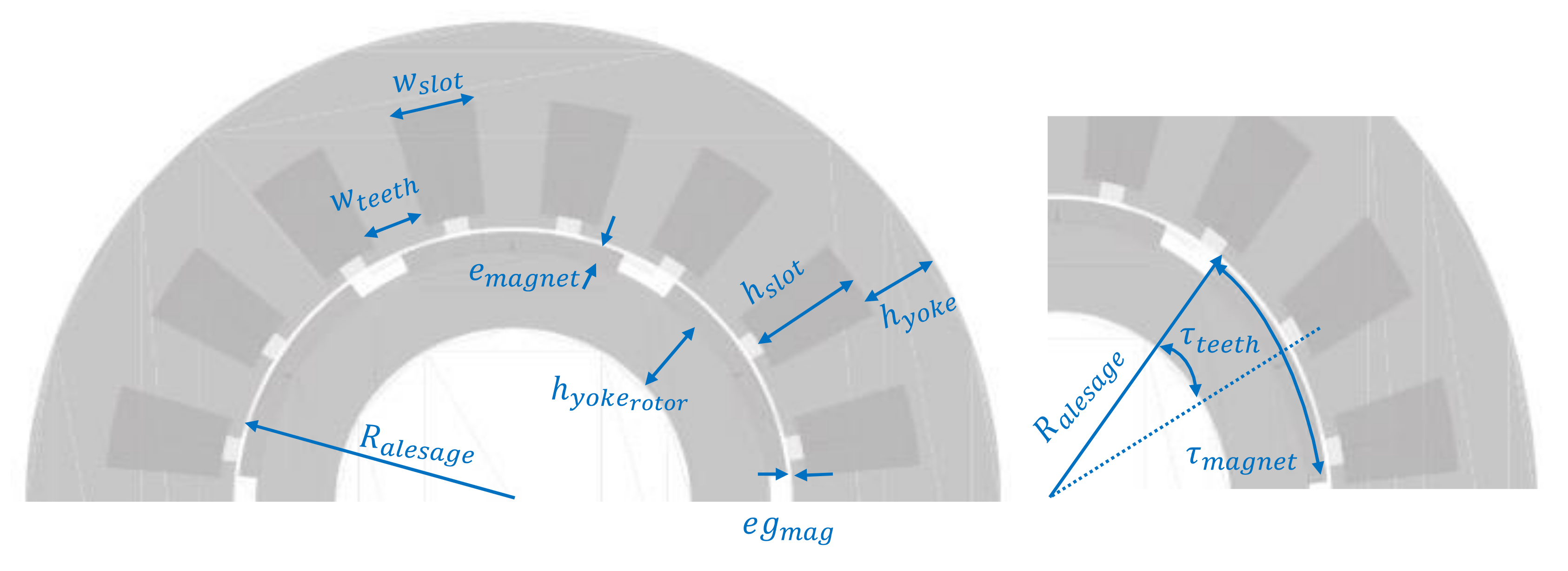
The electric machine geometry presented in
Figure 4 corresponds to a SM-PMSM. It is the most promising topology in the aeronautic field, having the highest specific power among all machine types. Moreover, this topology can ensure flux density in air gap very close to sine wave, with very low saliency. Thus, with a sine wave-distributed winding, the analytical modeling is not too complex but is accurate enough for system integration [
34]. From the set of sizing variables presented in
Table 1, each dimension of the electric actuator can be calculated (see
Figure 4): more information is available in [
14,
17].
This analytical model has been checked by a finite element software [
33].
The computation of the first harmonic of the air gap flux density,
, comes from geometrical decision variables. The electric angle,
, is half of the pole pitch angle,
. The root mean square value of the first harmonic flux density in the air gap is provided in
Table 2.
All the other dimensions are determined by the decision variables (see
Table 3).
In our model, slots are rectangular, and the slot length can be found according to
Table 4.
The centrifugal pressure and the peripheral speed will be used as mechanical constraints. Thanks to the actuator dimensions, the centrifugal pressure exerted on the carbon sleeve from the maximum mechanical rotational speed value of the electric actuator,
, can be estimated (see
Table 5).
The maximum centrifugal pressure, , and maximum peripheral speed, , constraints are set in order to design the right carbon sleeve thickness.
3.2. Partial Discharges Model
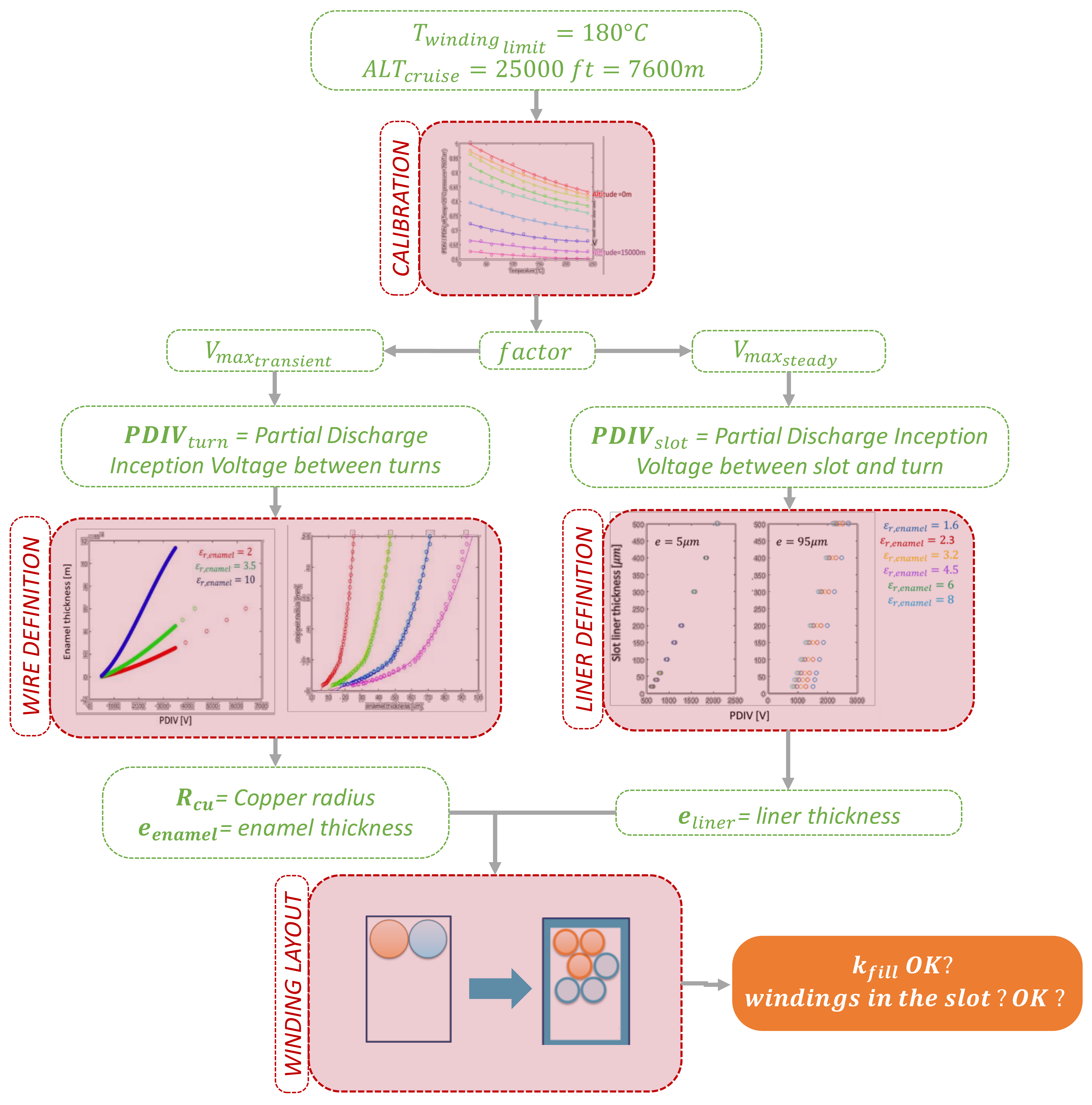
Partial discharges in electrical machines represent an important issue for systems’ reliability, especially in the context of a more electric aircraft where the combination of fast switching devices and long cables between power electronics converters can cause non-negligible overvoltage and lead to premature failures [
35,
36]. A complete study related to the electric insulation issue and especially the partial discharges that may appear with high-voltage-fed machines was achieved in Philippe Collin’s thesis [
21]. In order to take this issue into account in an integrated MDO framework, the process is as follows: From the geometrical dimensions of the actuator, typically the number of conductors used in the windings, the partial discharges model sizes the insulation thickness required to avoid the corona phenomena appearance. A calibration abacus is used to take environmental conditions into account (temperature and pressure). In order to be conservative, the limit values have been used (limit temperature of the actuator and cruise altitude for the pressure). Then, a first set of parametric regression is used for the turn-to-turn insulation, increasing the thickness of the copper insulation, while the second parametric regression is used for the yoke-turn insulation, adding an insulation layer between the yoke and the conductors. The final part of this model checks if the windings have conveniently been integrated with all constraints. The final process is detailed in
Figure 5.
Thanks to this model, the penalty in partial discharges due to the rise of temperature in the windings and pressure conditions is taken into account in this study. The electric design is then related to electromagnetic, mechanical and thermal aspects, but also to partial discharge constraints.
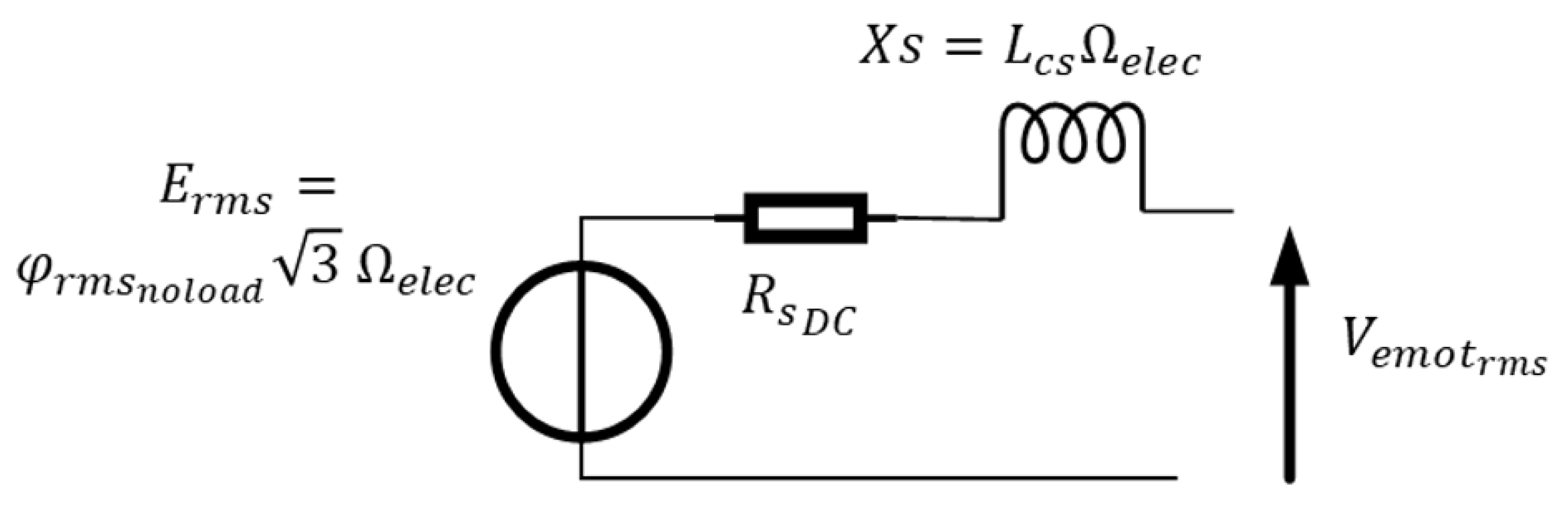
3.3. Performance Model based on Behn–Eschenburg Diagram
The Behn–Eschenburg linear model has been used in this study to characterize the actuator in phasor reference frame (see
Figure 6). The winding configuration derives from the geometrical dimensions and allows the computation of the electric parameters (see
Table 6).
Three parameters are used to control the electromechanical actuator, the DC resistor, , the cyclic inductance, , and the electromotive force, .
Once again, the dimensions of the actuator are required to calculate the electric circuit parameters, as detailed in
Table 7.
The control strategy can be implemented from these parameters. A maximum torque per ampere strategy (“
= 0”) has been performed with the capability of field-weakening over the mission. In particular, increasing speed leads to enhancing the motor voltage, which is limited by the bus voltage and the PWM source inverter: the amplitude of the motor voltage in the Park’s reference frame is limited (
, defined in
Table 8). Maintaining a certain level of torque at higher speeds than the base speed induces a negative current “
”: this “counter-field current” reduces the air gap flux “
”. This field-weakening operation operates at maximum voltage for high speeds.
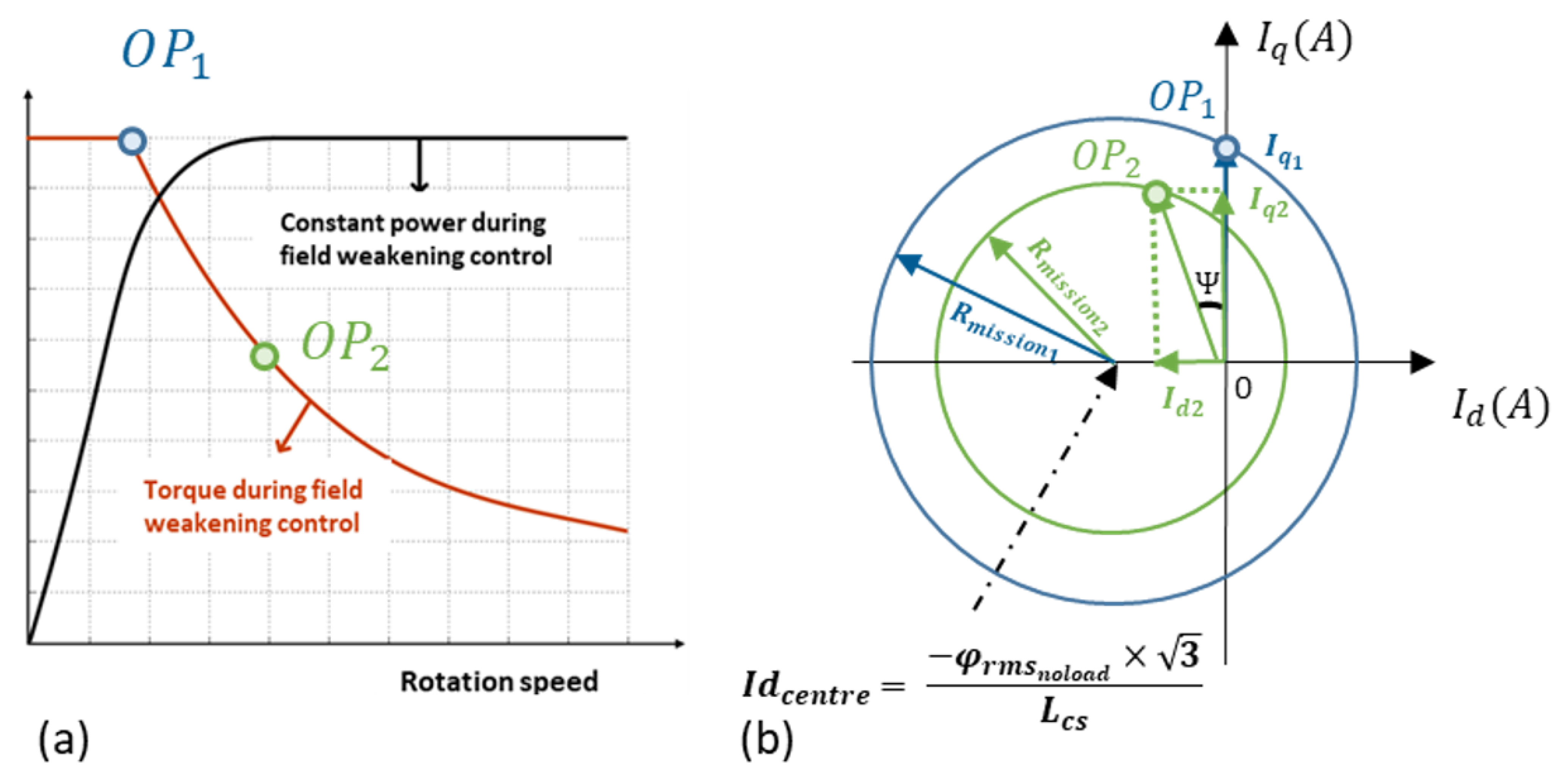
From a geometrical point of view, the radius of the actuator circle is defined by the maximum available voltage,
, and the actuator rotational speed over the flight mission,
(see
Table 8). The intersection between the actuator circle and the current vector defines the operation point (
OP1,2).
When the voltage is not limited (without field-weakening), the circle must contain the operating point (blue circle in
Figure 7b) and the equivalent condition is the following:
The inequation becomes an equation when the voltage of the electric actuator reaches the maximum available voltage,
. In this case, the field-weakening strategy occurs. The operating is then defined by the green circle. During that overspeed operation, the actuator usually operates at constant power, as illustrated in
Figure 7a.
The blue circle shrinks to the green circle (increasing speed) and the current is shifted in phase to reach the operating point (see
Figure 7b). Both operating points (
) are represented in the torque-speed plan (see
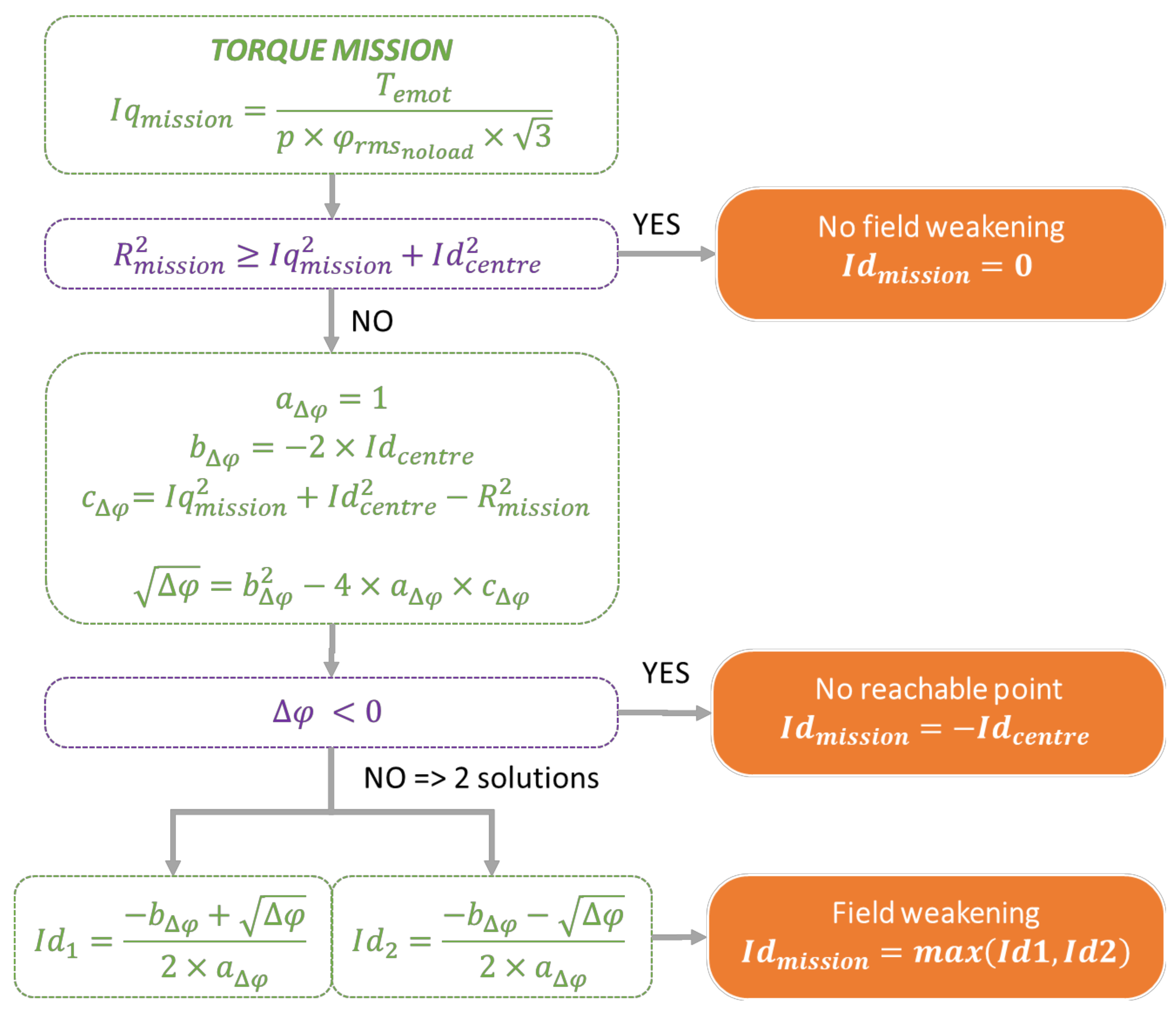
Figure 7a). The circle characteristic is defined by:
This second order is derived in
Figure 8 to set the current
in the case of the field-weakening operation:
Figure 8 shows the resolution process of the control strategy. The discriminant is computed to check if there are solutions. Finally, if solutions exist, the least restrictive
Id value is kept.
After this calculation process, the electromechanical actuator characteristics can be computed. The currents and voltages are derived from the
d,
q axis values (see
Table 9).
Once currents and electric actuator characteristics are determined, losses can be computed from the mission profile according to
Table 10.
The losses are the inputs of the thermal model used for determining the temperature constraints in each part of the e-machine. Note that the electro-thermal coupling in mono-directional as temperature variations do not influence motor parameters in our model.
3.4. Thermal Model Using a Nodal Network
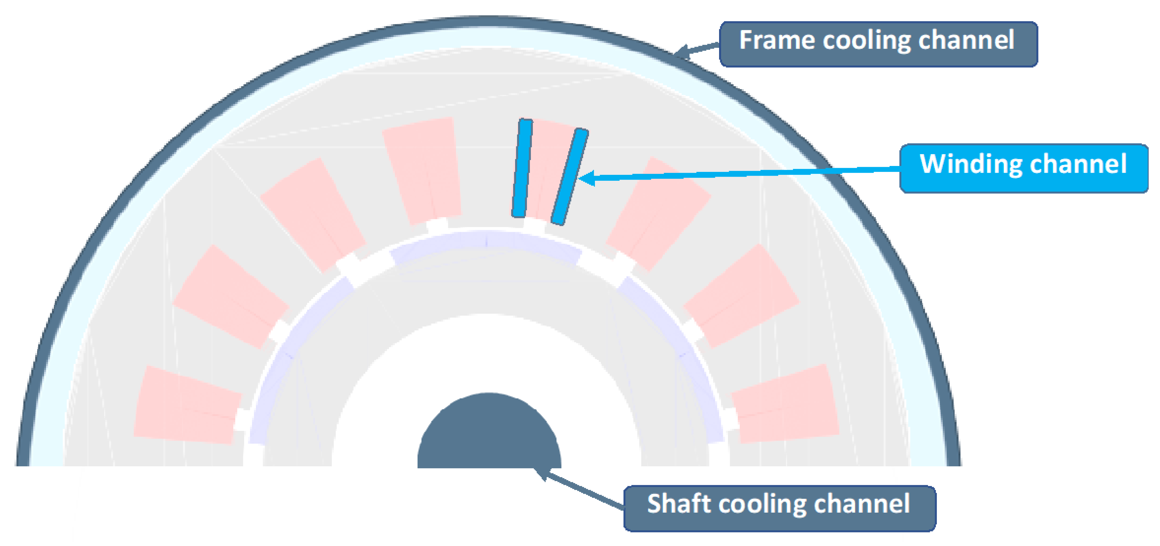
In the thermal modeling, two levels of a direct cooling device deeply studied in [
19] have been implemented in the optimization process:
“Base cooling” (first level), outside of the stator through a water jacket and inside of the rotor through a shaft cooling system.
“Internal cooling” integrated in stator slots (“winding channel”) of the electric motor: this second level involves a more efficient cooling.
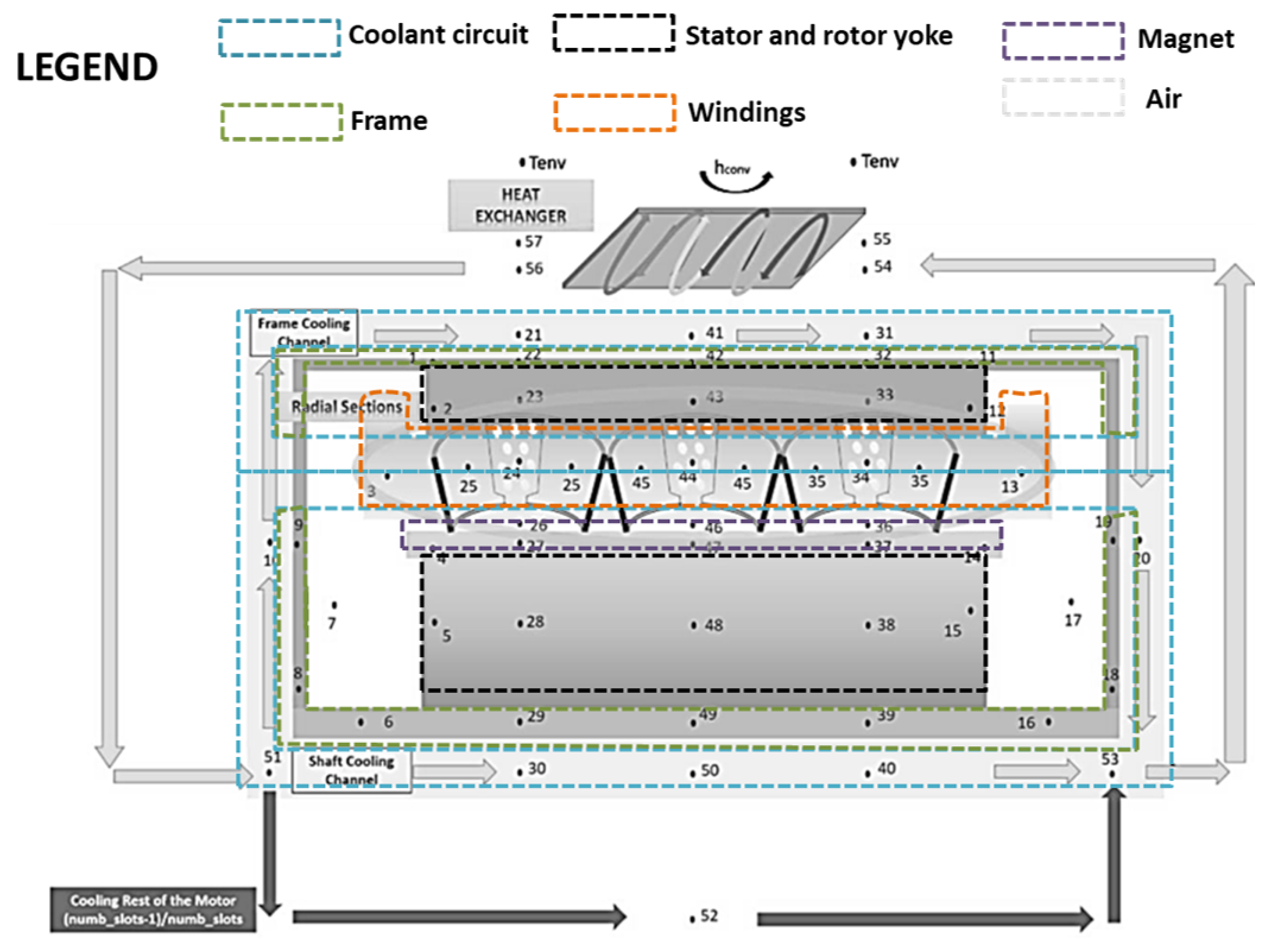
Both systems are water cooling circuits and are linked to a heat exchanger allowing to dissipate the heat flux in the plane environment (see
Figure 9 and
Figure 10).
The thermal model of the electric actuator and its cooling system is based on a lumped parameter thermal model: a nodal network is implemented in order to compute specific temperatures inside the actuator with a conductance matrix linking the different nodes. The capacitive transient effects have been integrated to filter the temperature transients inside the electric motor and to provide the temperature evolution during the flight mission. To do so, a thermal capacity matrix, G, of the motor system has been considered, with each capacity corresponding to the thermal capacitances of a given part of the system. Variations in input data such as the external temperature and the heat flow profile (motor losses profiles) are also considered. Thanks to this transient effect, the thermal limits can be released to achieve more compact and optimal sizing.
The thermal balance equation is as follows:
, where
C and
G are respectively the matrices representing capacity and conductance effects, and
T and
Ψ are the vectors representing temperatures and heat generation in the thermal system (see
Table 11).
The model is based on several simplifying assumptions: the thermal model is homogeneous in the axisymmetric rotor section, the radiation heat transfer is neglected and thermo-physical properties do not depend on the temperatures.
An implicit Euler method is used to solve these equations.
Table 11.
Flux and conductance expressions for each transfer mode.
Table 11.
Flux and conductance expressions for each transfer mode.
| Flux and Conductance Expressions |
|---|
| Heat Transfer Mode | Conductance | Heat Flow Expression |
|---|
| Conduction (axial and ortho-radial) | | |
| Conduction (radial) | | |
| Convection | | |
| Fluidic flow | | |
where:
is the surface of heat transfer between volumes represented by nodes and ,
is the surface exposed to convection heat transfer,
is the average temperature of the fluid surrounding surface ,
are the radius of nodes and (),
is the distance between nodes and ,
is the height of the cylindrical object,
is the heat transfer coefficient,
is the mass flow rate,
is the thermal conductivity,
is the thermal capacitance.
Each temperature results from the thermal balance equation. Three of them have been chosen as constraints: the end-winding, the stator yoke and the magnet temperatures. Thanks to these constraints, the electric motor optimization can be performed with the mass of all components (active part + cooling system) as the objective function.
4. The Cooling System: A Leading Challenge
In aeronautics, “mass is the enemy number one”. Cooling plays a key role in the sizing of electromechanical components and constitutes a leading optimization constraint.
In
Section 4.1, the difference between two thermal models has been firstly analyzed: a steady-state thermal model (R nodal network) and a transient model involving thermal capacitance effects (R,C nodal network). This comparative study highlights the importance of the coupling between the flight mission and the thermal modes which are simulated with the transient model (R,C) but not in the steady-state one. In
Section 4.1, a “base cooling” system is considered involving two subsystems: a water jacket for stator external cooling and a liquid-cooled shaft system for the rotor.
In
Section 4.2, the performance of the actuator optimization with this “base cooling” will be compared with a second level of thermal subsystem adding a stator slot “internal cooling” with the previous “base cooling”. The “internal cooling” device is directly integrated inside stator slots to be close to the heat dissipated by copper losses in windings.
4.1. Optimization Process
The clearing procedure [
37] was used for optimizing the PMSM mass with regard to the design constraints. Clearing is a niching elitist genetic algorithm which usually outperforms standard genetic algorithms on difficult problems with multiple non-linear constraints and multimodal features [
38]. All constraints were scaled and integrated into the objective function with penalty coefficients. The population size and the number of generations were respectively set to 100 and 200. Classical values for crossover and mutation rates were used (i.e.,
pc = 1 and
pm = 1%). For each optimization case, multiple runs were carried out in order to take the stochastic nature of the algorithm into account and to ensure the reproducibility of results.
The global set of decision variables is provided in
Table 12.
Most of the decision variables are geometrical parameters. From this set, the geometrical dimensions of the electric motor are defined. The electric circuit parameters are derived to compute the actuator losses. The profile losses are used in the cooling model to estimate the temperatures inside the actuator. Finally, the partial discharges model checks the integration of the windings into the slot to avoid the phenomena.
The constraints of the optimization problem are listed in
Table 13. The first six constraints are checked after the electric motor model and the next three, which are related to the cooling model, are verified by simulating the flight mission. Finally, the last three constraints are calculated from the partial discharges model. When one constraint is not fulfilled, a penalized value (function of the number of constraints checked or not) is returned to the optimizer to facilitate the optimization convergence in a continuous way. Once all constraints are satisfied, the mass of the electric machine including its cooling is returned (being the objective function) to the optimizer. An optimal solution is found after the launch of 200 independent runs. This optimization process highlights the interaction between the sizing of an electromechanical component and its cooling.
4.2. Thermal Modeling: The Importance of Transient Modes Coupled with the Flight Mission
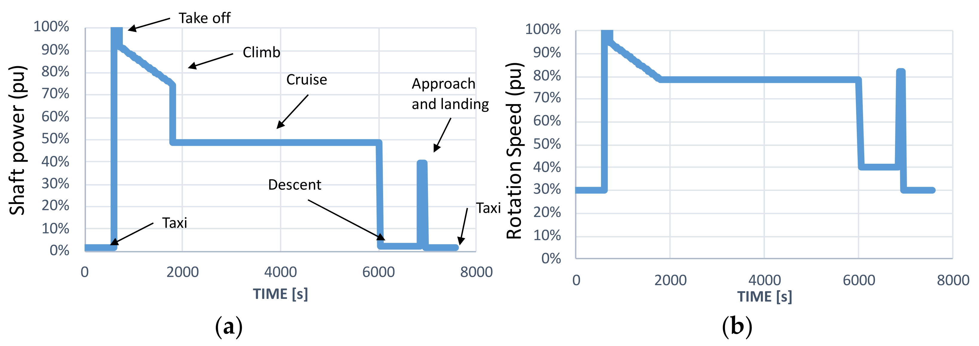
The reference flight mission profile integrated into the optimization is depicted in
Figure 11. In this figure, shaft power and corresponding rotational speed are represented in per unit versus time during all flight phases (Taxi, Take off, Climb, Cruise, Approach and Landing, Taxi). The electric motor sizing and optimization are then performed by integrating the flight cycle in the loop according the MDO process described in
Figure 2. All losses over the flight mission were computed according to the control strategy presented in
Section 3.3.
Three different optimizations are carried out in the following sections: two are related to the e-motor with the base cooling (2025 target) presented in
Section 3.4, using a steady-state or transient thermal model. The third optimization is applied on the e-motor with internal cooling (2035 target) using a transient thermal model.
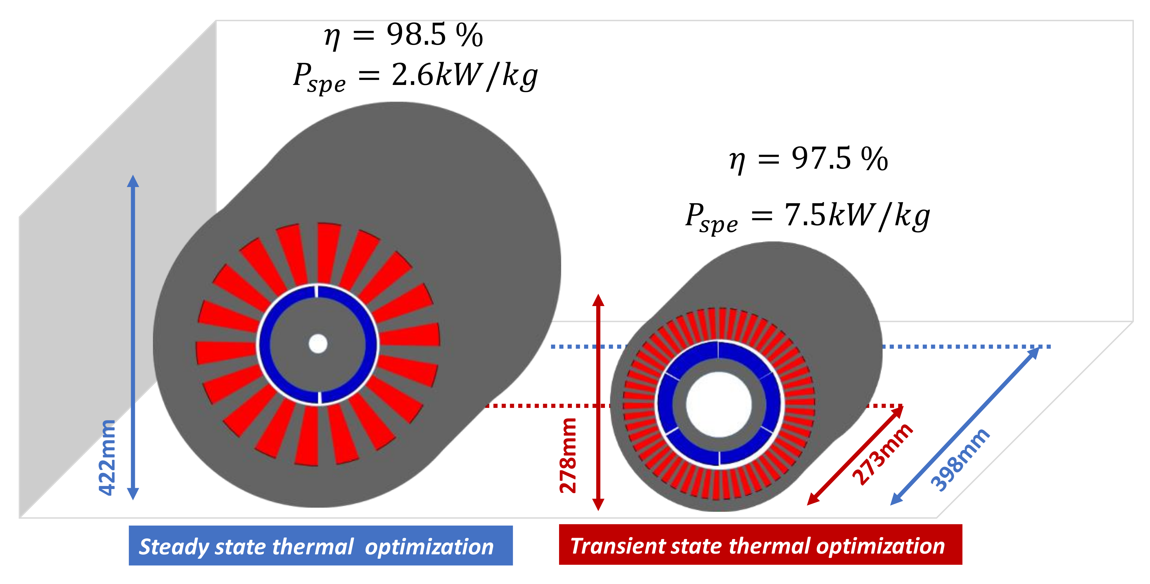
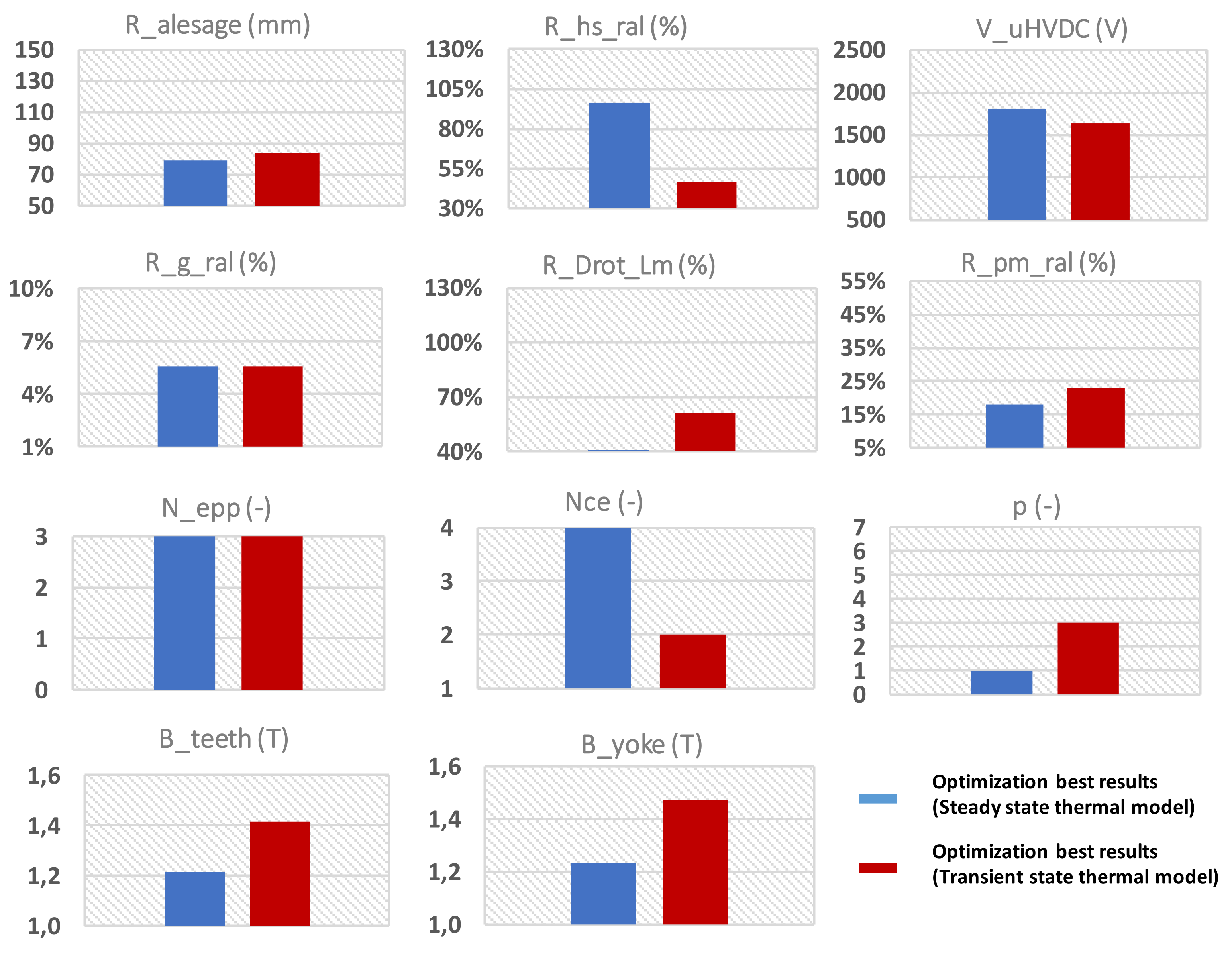
A first level of thermal modeling has been used to optimize the electric motor mass: “the steady-state model” (in blue, left,
Figure 12). A second level of “transient thermal model” involving transient modes is compared (in red, right,
Figure 12). The improvements between both models are spectacular: the specific power has been multiplied by three (2.6 vs. 7.5 kW/kg), meaning that transient phases are highly sensitive regarding the motor sizing. In fact, the yokes based on magnetic sheets involve significant thermal capacitances which filter the temperature variations. As a result, the trade-off between specific power and energy efficiency is influenced by the thermal behavior: increasing the specific power of the electric actuator by considering thermal transient modes tends to decrease its efficiency. In that case, with the e-motor being less sensitive to losses, the latter are increased by lowering the mass.
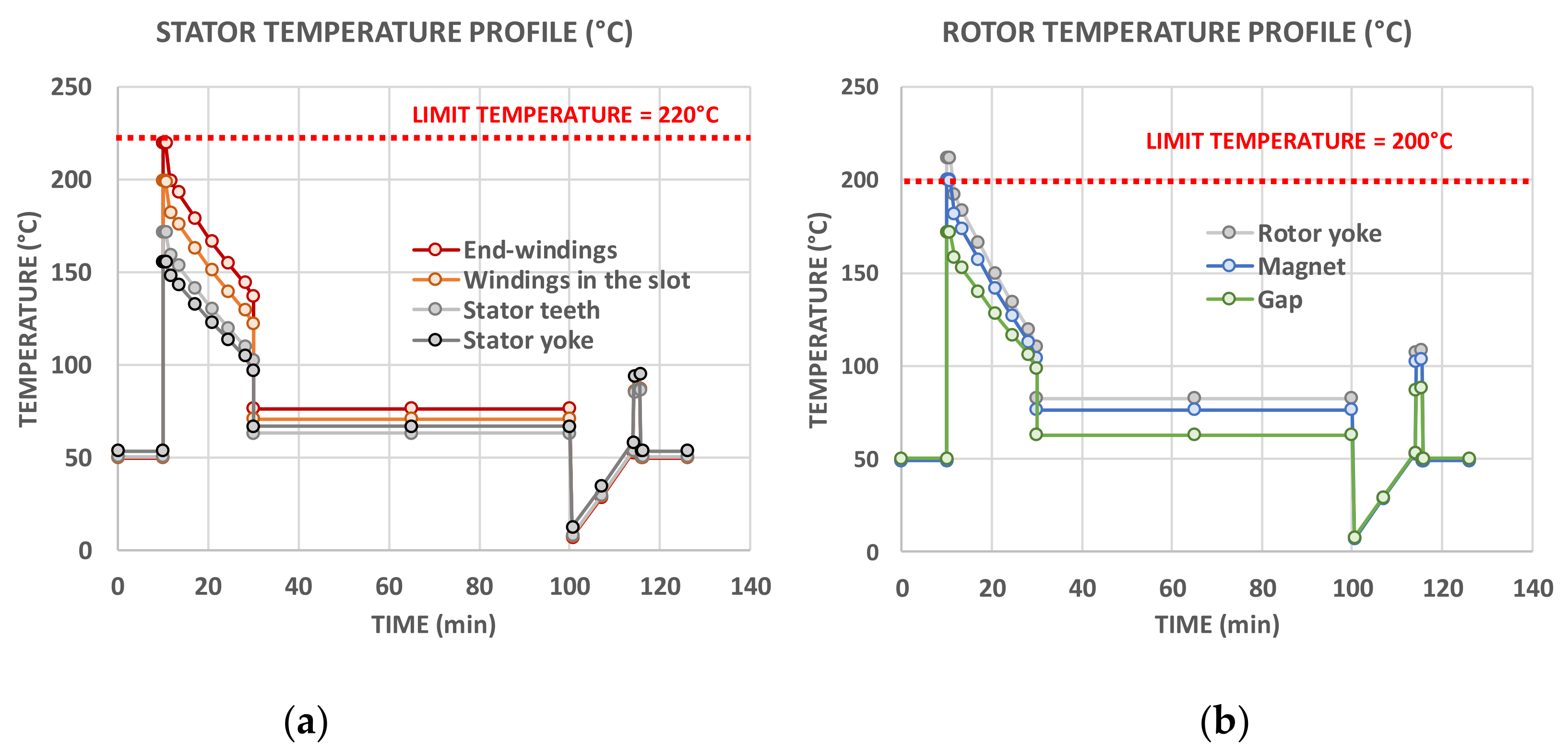
A limit temperature of 220 °C has been used for the end-windings and the stator yoke in the optimization based on the “steady-state thermal model”; with this model, thermal limits have been released knowing that thermal capacitance effects would filter the thermal transients. For the “transient thermal model”-based optimization, a lower value (180 °C) has been taken to be conservative and safer. In the same way, two limit values have been used for the magnets: 200 °C for the “steady-state model”-based optimization and 150 °C for the transient.
Regarding the steady-state thermal model-based optimization, the maximum of the temperature values is reached during the take-off because of the high-power demand (see
Figure 13). This steady-state temperature profile is really penalizing: electric and magnetic loads have to be reduced to satisfy thermal constraints during take-off, reducing losses (better efficiency) but increasing the actuator mass.
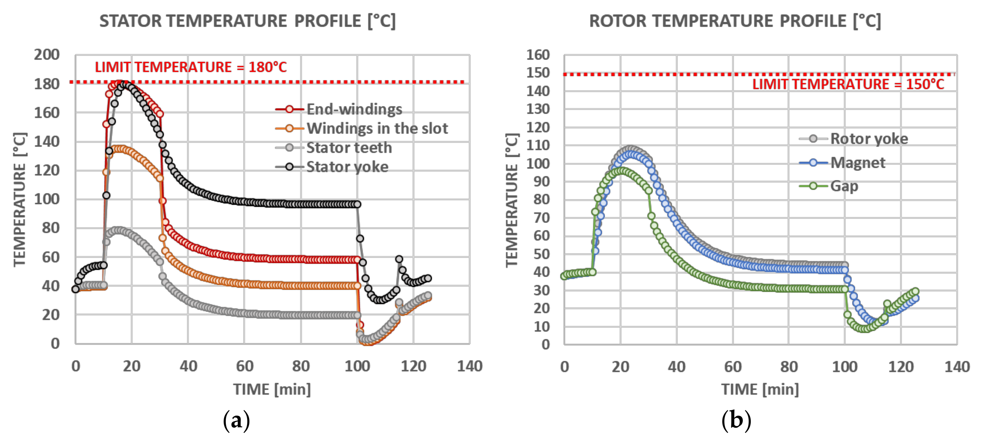
On the contrary, simulating transient modes involves filtering effects during the flight mission: the maximum values of temperatures are now switched at the top of the climb, because of the transient phase, which allows delaying the temperature rise (see
Figure 14).
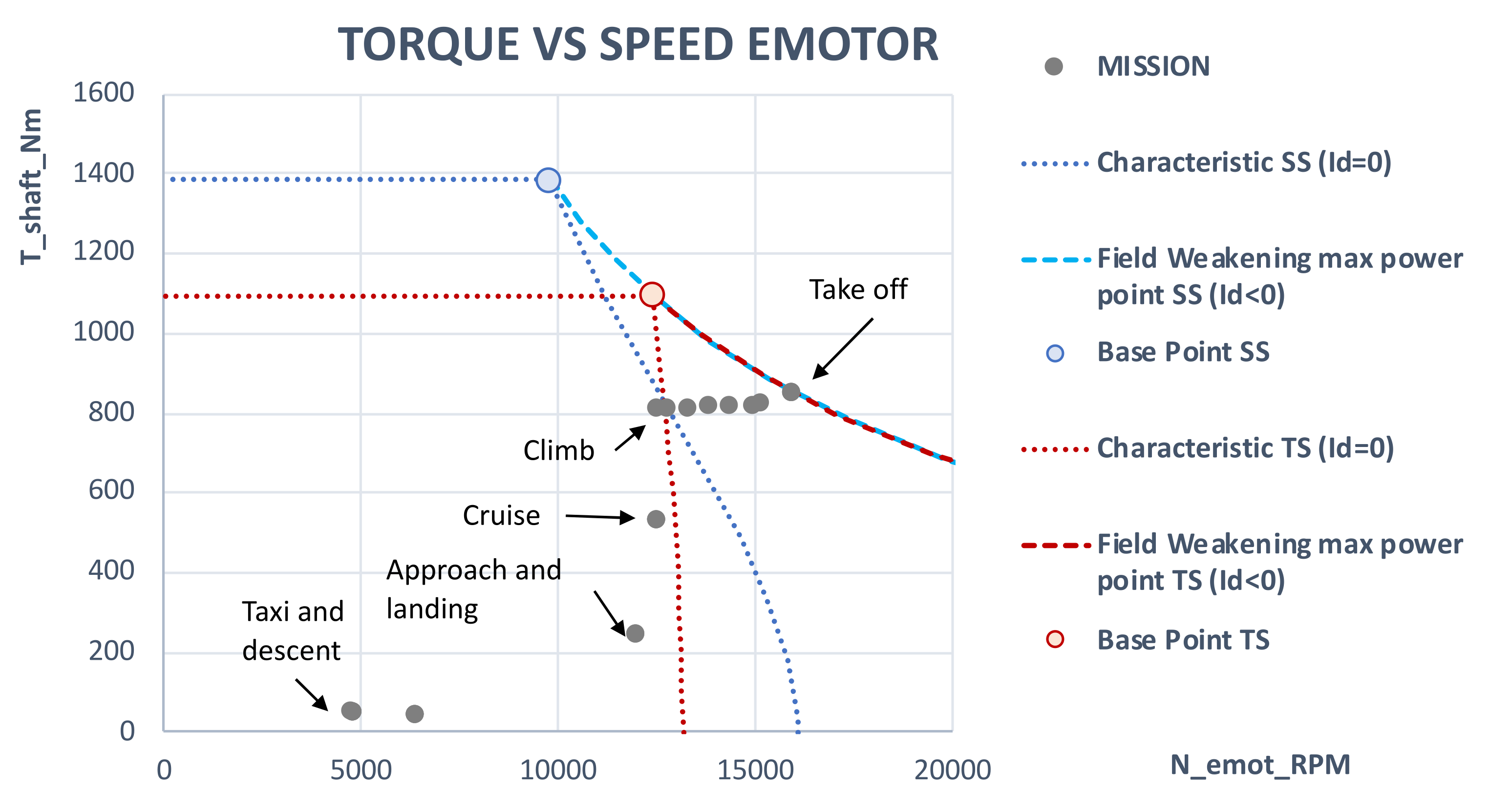
Furthermore, the transient behavior during a flight mission is also influenced by the control strategy. In order to be able to make a performance comparison, the torque-speed characteristics of both actuators are displayed in
Figure 15 (in blue for the e-motor obtained with a steady-state (SS) thermal model, in red for that associated with the transient state (TS) thermal model and in grey for the situation of the “mission points” for each flight sequence). The actuator characteristic is limited by a maximum current (maximum torque), while its speed limit is set by a limit voltage (
Vdqmax) related to the power electronic supply (related to the bus voltage,
VuHVDC, see
Table 8). When this limit voltage is reached, the control strategy is as follows:
Reduce the Iq current of the actuator, allowing it to go into a higher-speed phase without shifting the current (Id = 0).
Add negative current in the d-axis of the actuator (Id < 0) to reduce the flux density (field-weakening) in the air gap, thus operating at constant power by increasing speed.
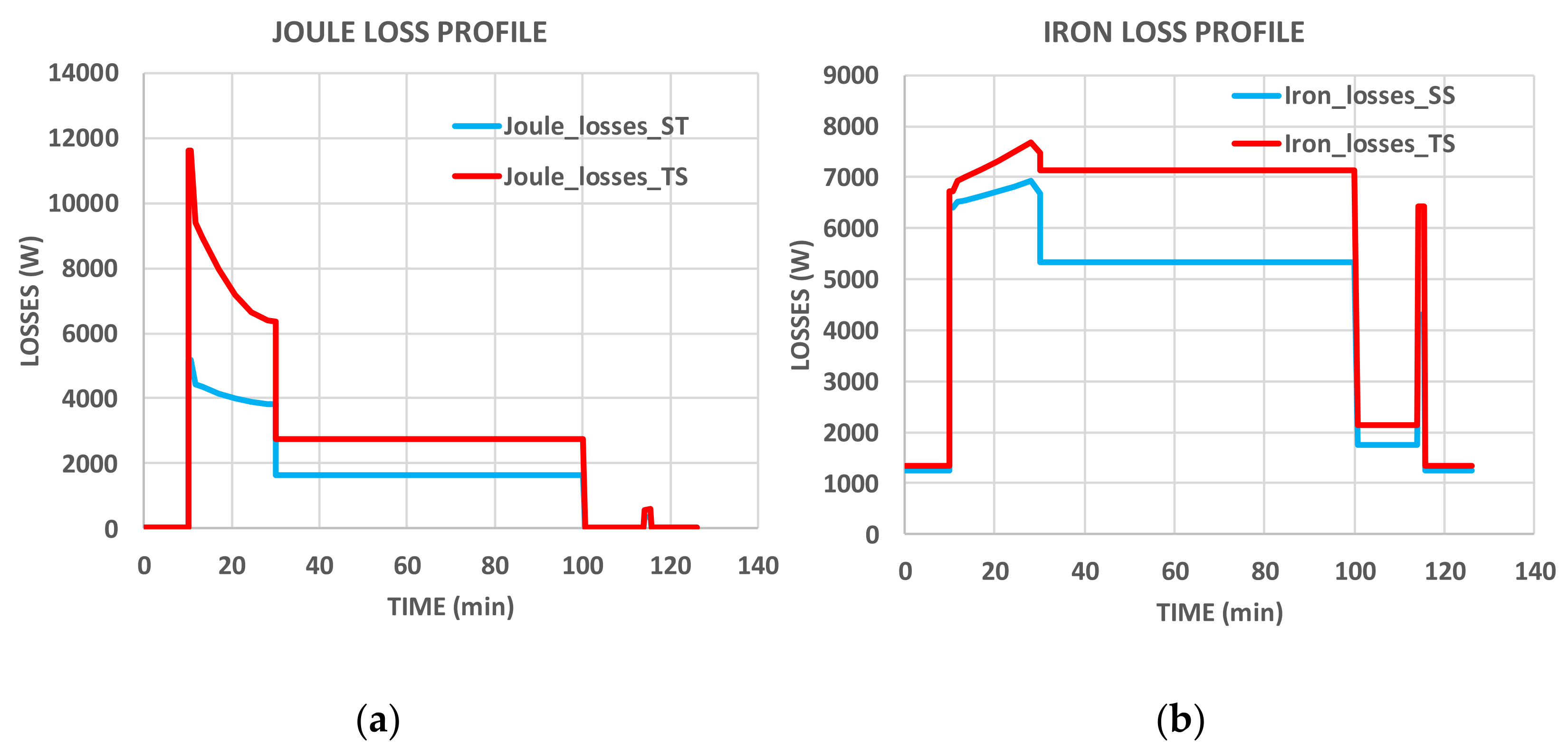
Both optimized machines (with both thermal models) use field-weakening capabilities. The field-weakening strategy optimizes the loss balance, reducing iron losses when the Joule losses are at their maximum (see
Figure 16). Field weakening is exploited in both optimizations (SS and TS) at exactly the same time during take-off and almost during the whole duration of the climb.
The loss profile highlights the difference between both e-motor optimal designs.
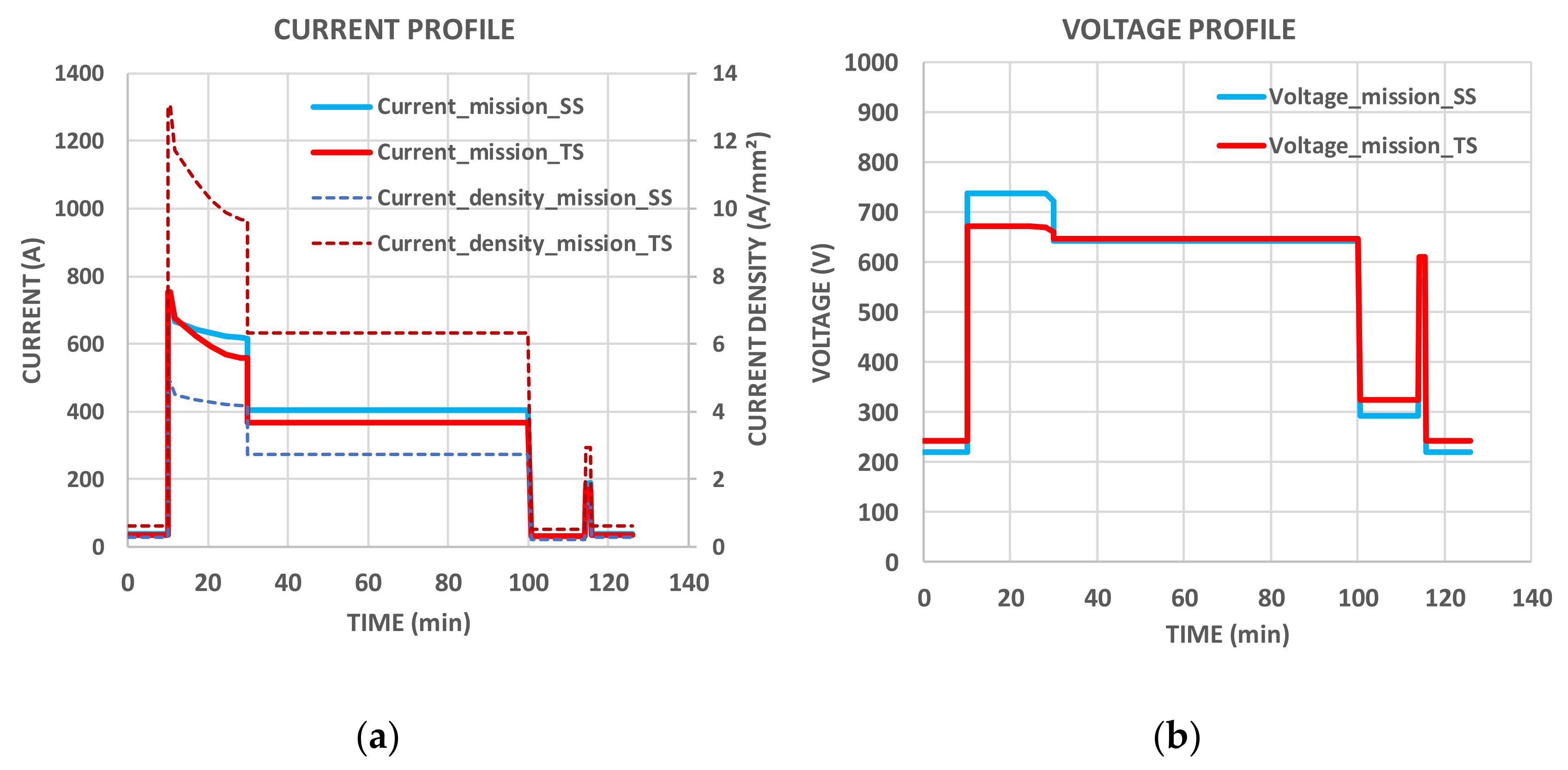
Figure 17 completes the analysis: the voltage reaches a maximum value (field-weakening) during the take-off/climb phase, while the current is increased. Regarding the absolute values, the current and the voltage have similar values for both optimizations, but the main difference resides in the current density, which is multiplied by three for the TS optimization.
With lower thermal constraints (as in the case of the transient thermal model), the number of pole pairs (see
Figure 18) can be increased (also increasing iron losses) to reduce the actuator size. The field-weakening strategy allows counterbalancing the iron loss increase by lowering them during takeoff and climb sequences when the power demand is maximum (see
Figure 16). Finally, thanks to this “thermal-control-mission” coupling, the specific power has been multiplied by three between both optimizations.
4.3. Sensitivity of the Cooling Performance
In order to once again increase the specific power of the electromechanical actuator, a second cooling solution has been implemented, adding an “internal cooling” (directly into the stator slots) to the “base cooling” (see
Figure 9). As mentioned previously, the objective function is the electric motor mass, including the cooling system. The same set of decision variables has been used with the same list of constraints: only the cooling system has been changed. Let us recall that the “base cooling” is composed of a stator water jacket and a rotor shaft cooling.
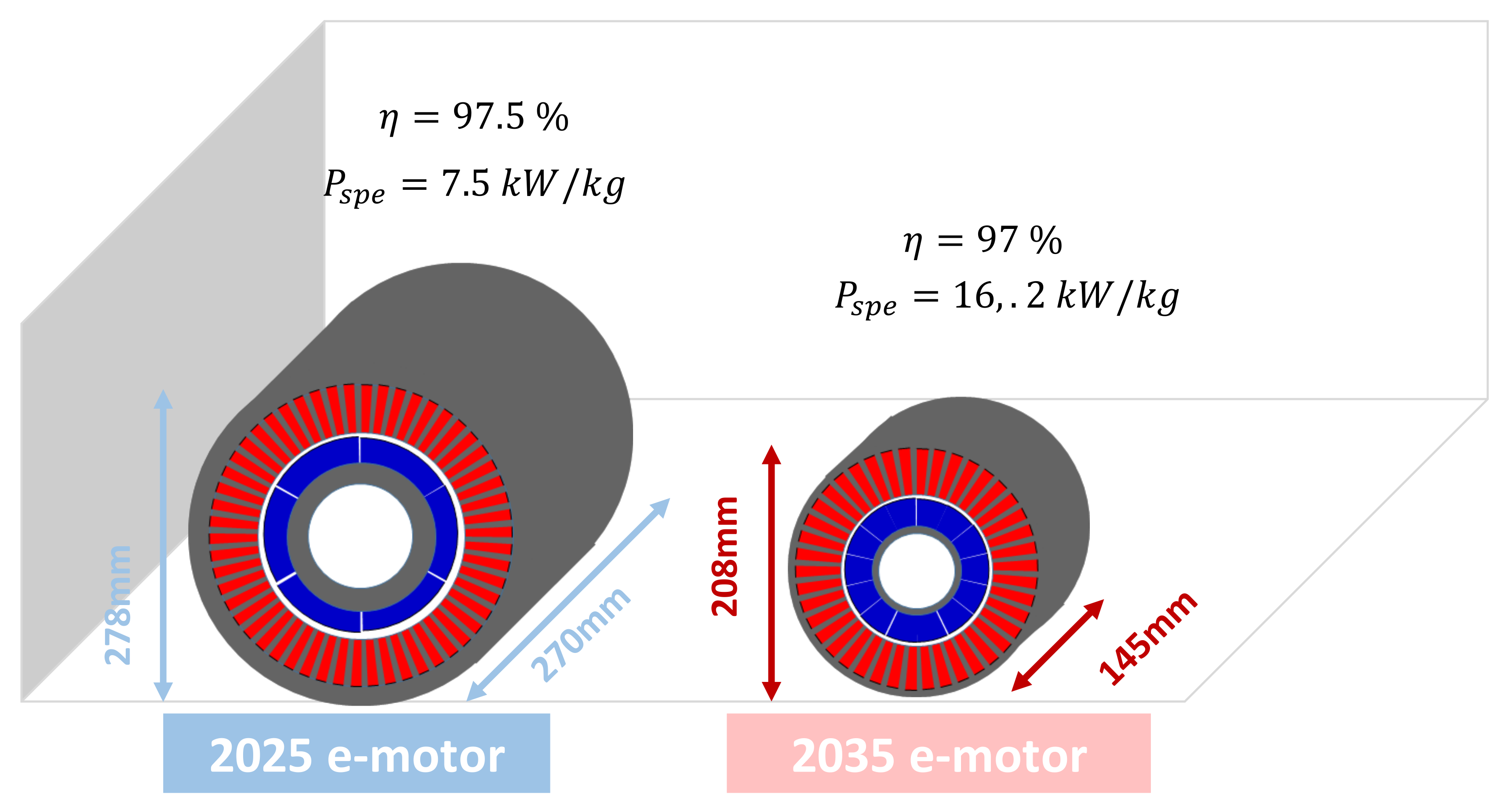
Adding the “internal cooling”, the Joule losses are directly dissipated inside slots by the cooling channel. It also involves differences in terms of thermal dynamics: losses of the electric actuator are important with this high-performance cooling regarding the volume of the machine, and the transient phase is faster than before (see
Figure 19). Once again, the stator yoke and the end-windings are the limiting temperatures and the magnet temperatures have been reduced because of the efficiency of the new cooling system. Enhancing the performance of the cooling device allows to significantly increase the specific power of the electric motor by a ratio higher than two (see
Figure 20).
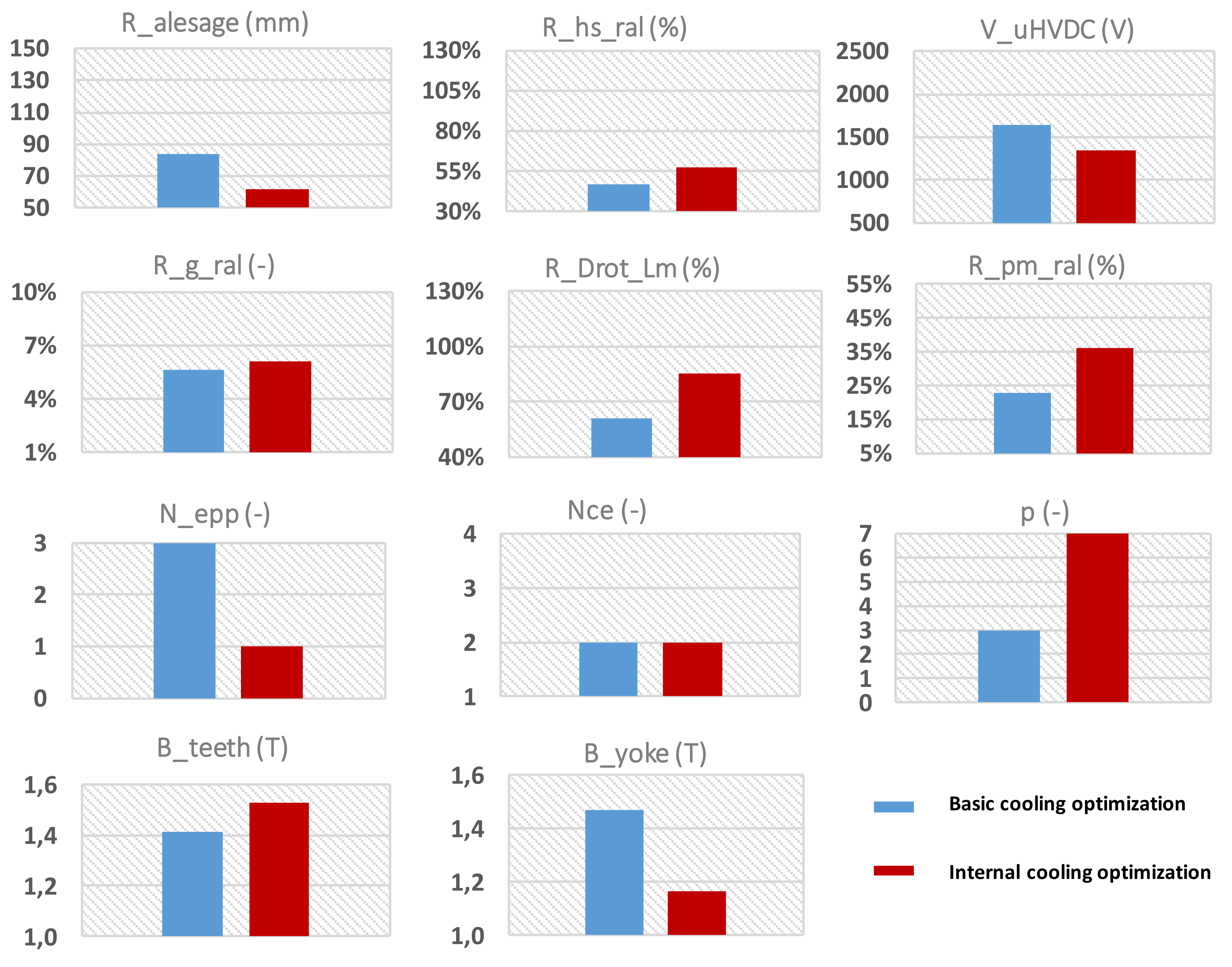
Regarding the decision variables, the inner stator radius has been reduced and compensated by a higher current density (related to the ratio between the slot height and the inner stator radius) thanks to the internal cooling system (see
Figure 21). Bigger magnets (
) are obtained to increase the air gap flux density. The DC bus voltage is indirectly lowered with the internal cooling system optimization because of the integration of the cooling channel into the slots. Indeed, the directly cooled slots are so small that any space gain is important for the optimizer, leading to the reduction of the insulation thickness and of the insulation layer used for the copper; with this second optimization, the filling factor is close to 70%. The same trend is observed for the number of slots per pole and per phase (
): the slots area cannot be too small while the internal cooling channel is integrated, which lowers
values. Increasing the number of pole pairs considerably reduces the yoke thickness and other sizes of the actuator. However, greater iron losses are expected, which is managed by the high-performance cooling. The same explanation can be used for the flux densities in the teeth: the cooling channels are in touch with the windings and the stator teeth, so the flux density in the teeth can be maximized. The yoke flux density has been decreased to minimize the iron losses in the yoke.
5. Conclusions
In this paper, a MDO was applied to a PMSM actuation system dedicated to a regional aircraft powertrain. This process involves a large set of multi-field couplings between electrical, geometrical, mechanical and thermal aspects, integrating the control strategy over the flight mission and also taking numerous optimization constraints into account. Among the environment constraints, partial discharges induce insulation issues for high-voltage electric actuators. The proposed study constitutes a preliminary step before the optimization of the whole powertrain embedded inside future hybrid electric aircrafts. With “mass being the enemy number one” in aeronautics, and while the electric motor is one of the most sensitive elements among all powertrain devices, we have focused this study on the mass reduction of the electric motor and its cooling. An analytical modeling of the electromechanical and thermal parts allows optimizing the actuator system. This model is a good trade-off between accuracy (at the system design level) and efficiency in terms of computational time to consider a future optimal integrated design at the whole powertrain level.
The main results of this MDO approach are related to the influence of thermal aspects, which constitute the leading constraint to enhance specific powers for electro-mechanical actuation. First, the influence of thermal transients during the flight mission has been highlighted, showing that main (copper and iron) losses can be balanced over the flight mission thanks to an optimal control involving field-weakening capabilities: this is a typical example of triple systemic coupling between the thermal model, the control strategy and the flight mission cycle. Second, it has been demonstrated that enhancing the performance of the thermal system by adding an internal cooling device directly inside stator slots strongly increases the power density of the electric motor. With the most performant cooling and with exploiting transient control of thermal modes over the flight mission, the specific power of the actuator system with its cooling may be beyond 15 kW/kg, which is a promising result for the field of hybrid electric propulsion in aeronautics.


 ,
, 


