
Continuous Rapid Accurate Measurement of the Output Frequency of Ultrasonic Oscillating Temperature Sensors †

Department of Engineering and Mathematics, Sheffield Hallam University, Sheffield S1 1WB, UK
*
Author to whom correspondence should be addressed.
†
Presented at the 9th International Electronic Conference on Sensors and Applications, 1–15 November 2022; Available online: https://ecsa-9.sciforum.net/ .
Eng. Proc. 2022, 27(1), 56; https://doi.org/10.3390/ecsa-9-13340
Published: 1 November 2022
(This article belongs to the Proceedings of The 9th International Electronic Conference on Sensors and Applications)
Abstract
:Ultrasonic oscillating temperature sensors (UOTSes) allow sensing aggregate temperatures across, for example, a complete room, and react to the temperature changes within milliseconds. However, their output frequency is to be measured with relatively high accuracy (standard crystal oscillators might be insufficient) and resolution (down to 0.01%). For this reason, wide adoption of these sensors requires development of a robust, inexpensive and convenient way of measuring their output frequency. We tested various microcontrollers and ways of measuring frequency using built in timers. Utilising the direct memory access (DMA) mode for STM32 microcontrollers allowed recording measurements for every half period of the incoming frequency. Despite every individual measurement being inaccurate on its own, their moving average allows achieving arbitrary accuracy (at the expense of measurement latency) along with providing frequencies after every half period of the UOTS output pulses. This capability not only exceeds the needs of, say, room temperature measurement, but also provides an opportunity to study short-term variations in aggregate temperatures that can be useful for studying non-stationary heat distributions and flows.
1. Introduction
Frequency control and measurement play a crucial role in various areas of electrical and electronic engineering, i.e., electricity networks and telecommunications. The major advances in the field are associated with the development of crystal oscillators and atomic clocks, which enabled inexpensive but accurate oscillators and ultimate frequency accuracy and stability, respectively. The availability of such oscillators allowed precise synchronisation of generating electrical grids and high throughput communications. Our interest in frequency measurement is primarily related to the development of UOTses as their output frequency changes with the sensed temperature [1].
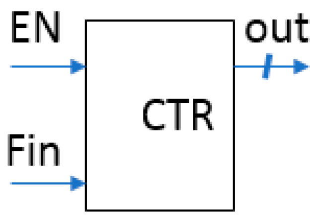
Frequency measurement involves benchmarking the frequency in question against a reference one . Well-established approaches involve using a gated counter that is connected to both the clock sources (Figure 1). If >> , the source is used for enabling the counter. Otherwise, the Enable input is connected to the source of .
Two clocks are generally not synchronised (i.e., derived from two different oscillators); the / (or /) ratio is fractional. The counter produces an integer value, effectively cutting off the fractional part of the ratio. The relative accuracy of frequency measurement can thus be calculated as
Consequently, the higher the ratio between the frequencies, the higher the measurement accuracy.
Although various sensors vary their output frequency as the response to the sensed value [2], our interest towards measuring the output sensor’s frequency is primarily related to the ultrasonic oscillating temperature sensors (UOTSes) that can operate in various media [1,3]. UOTSes can operate in liquids at the centre frequency of hundreds of kHz but require frequency measurement with an accuracy of a few Hz [3]. Because of such a relatively high frequency of operation, providing the / ratio in order of 10,000 using an inexpensive reference oscillator is very complicated if at all possible. A better solution would be to employ several (rather than one) gating pulses [4,5].
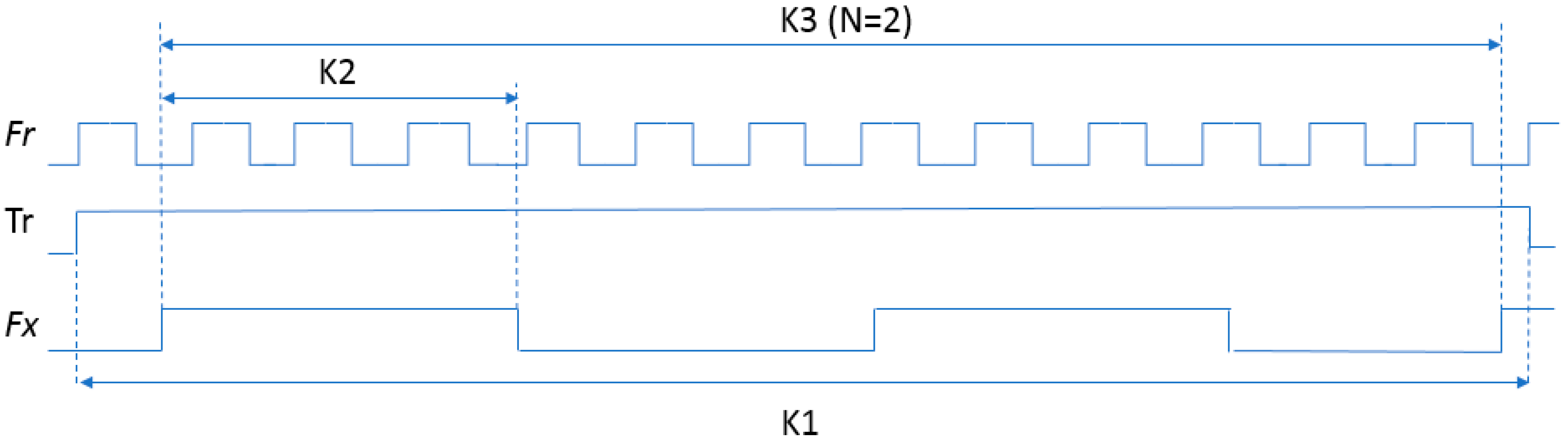
Figure 2 (where Tr is the reference time interval that was derived from an appropriate number of pulses) illustrates various methods for frequency measurement.
If > (which holds for known UOTSes), the pulses gate the counter that counts K2 Fr pulses. (If pulses are used to define the reference time interval Tr, the interval is used at the Enable input of the counter, which counts K1 pulses of . This mode was frequently employed in frequency meters in the past. By making Tr proportional to 10 s, 1 s, 0.1 s, etc., it became possible, by altering the position of decimal point, to display the counter value as directly.) If several UOTS pulses are used to gate the counter, the latter ends up with a considerable higher reading K3 (shown for the number of gating pulses N = 2 in Figure 2), which increases the frequency measurement accuracy accordingly:
This measurement scheme was successfully implemented by using discrete logic [5] and integrated circuits with proprietary architecture (namely Programmable Systems on Chip PSOC-1 [3,4]). As we attempt to use conventional microcontrollers (MCUs) in our air UOTS design, we compared various ways of using built-in MCU timers for measuring the output frequency, which belongs to the range 40 ± 2 kHz [1]. An STM32G474 MCU was used in our experiments because of our familiarity with this series, but the results are applicable to other MCUs.
2. Different Methods for Frequency Measurement Using MCU Built in Timers
An MCU timer can be used for frequency measurement directly in its Capture mode, which operates similarly to the gated counter. , usually generated internally, is supplied to the timer’s clock input, and , acting as the gating signal, is supplied to the Capture pin. The timer counts the clock pulses between the two consecutive edges of then typically generates interrupt that allows the central processing unit (CPU) to process the captured count. Unfortunately, typical MCU timers cannot keep counting for a few periods of on their own.
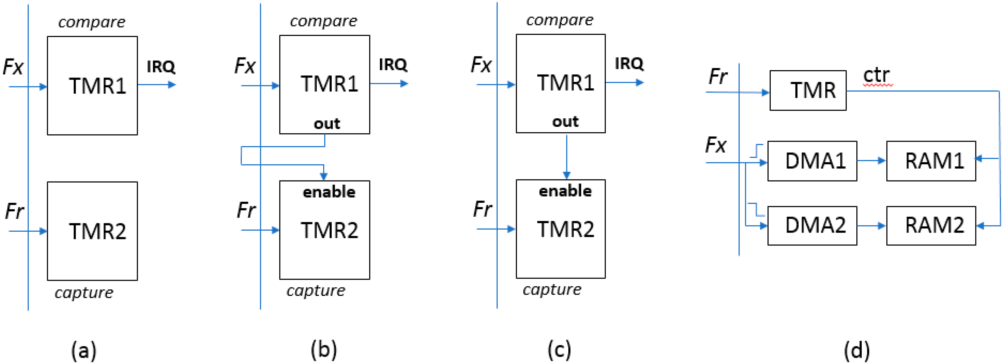
Most MCU feature multiple timers that can be combined. Figure 3a presents two timers that start counting and pulses at the same time. When TMR1 counts to the chosen value of pulses N, it generates an interrupt and MCU reads the accumulated value from TMR2. As responding to interrupt and reading TMR2 requires some CPU cycles, the read value might become inaccurate. Additionally, resetting the timers cannot be done truly synchronously resulting in increase in measurement error.
A better accuracy can be achieved when the output of -connected timer gates another timer (Figure 3b for external connection, suitable for most MCU timers, and Figure 3c for timers with internal synchronisation, available for STM32 MCUs [6]). This way, the TMR2 stops counting after the set number of pulses, thus the MCU reads the accurate value. Unfortunately, the timers’ tandem cannot operate for the following period of because it takes MCU some time to read and store the count. For this reason, it is impossible to obtain continuous stream of the counted values, which is desirable for UOTS measurements.
The CPU involvement can be avoided completely if the timer transfers counted values to the MCU memory using direct memory access (DMA) mode (Figure 3d). In our development, we followed a video walkthrough tutorial [7] and relevant code [8] to implement this mode of operation. Both rising and falling edges of trigger the DMA transfers, and the CPU is notified by an interrupt when the count for each half-period of is captured and transferred to the MCU memory.
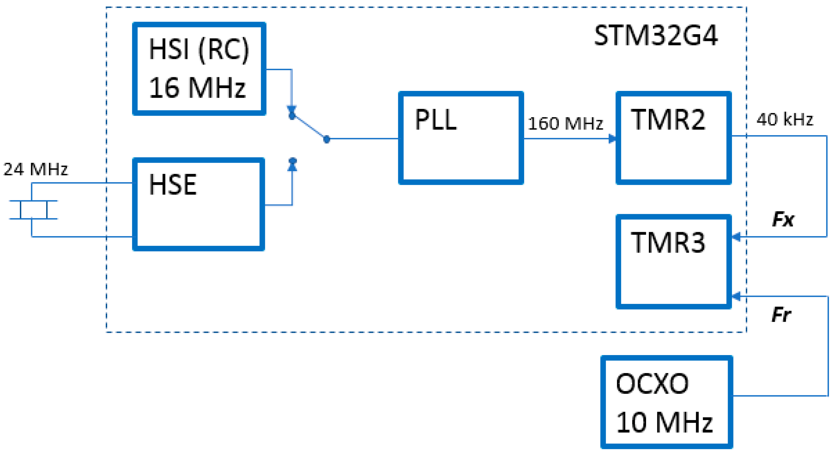
In order to verify accuracy and convenience of this measurement arrangement, we used one STM32 timer (TMR2 in PWM mode) that generated 40 kHz pulses from two primary oscillators—high-speed internal (HSI, RC-oscillator with accuracy and stability in the order of ±1% [9]) and high-speed external (HSE). The HSE oscillator was connected to the 24 MHz crystal available on the STM32 Nucleo-G474RE board and its accuracy and stability was determined by the crystal, typically in the order of ±v50 ppm. TMR3 was configured to operate in the DMA mode, counting the pulses from the Vectron C4550A1 (Vectron International, Hudson, NH, USA) oven-controlled oscillator (OCXO) with the stability of ±50 ppb [10] as shown in Figure 4.
The interrupt service routine counted the interrupts and flagged up when the data for chosen number of pulses N were fully collected in the memory buffer. The individual half-period counts were then averaged. In total, a 100 ms delay was actioned before starting the following measurement.
3. Experimental Results
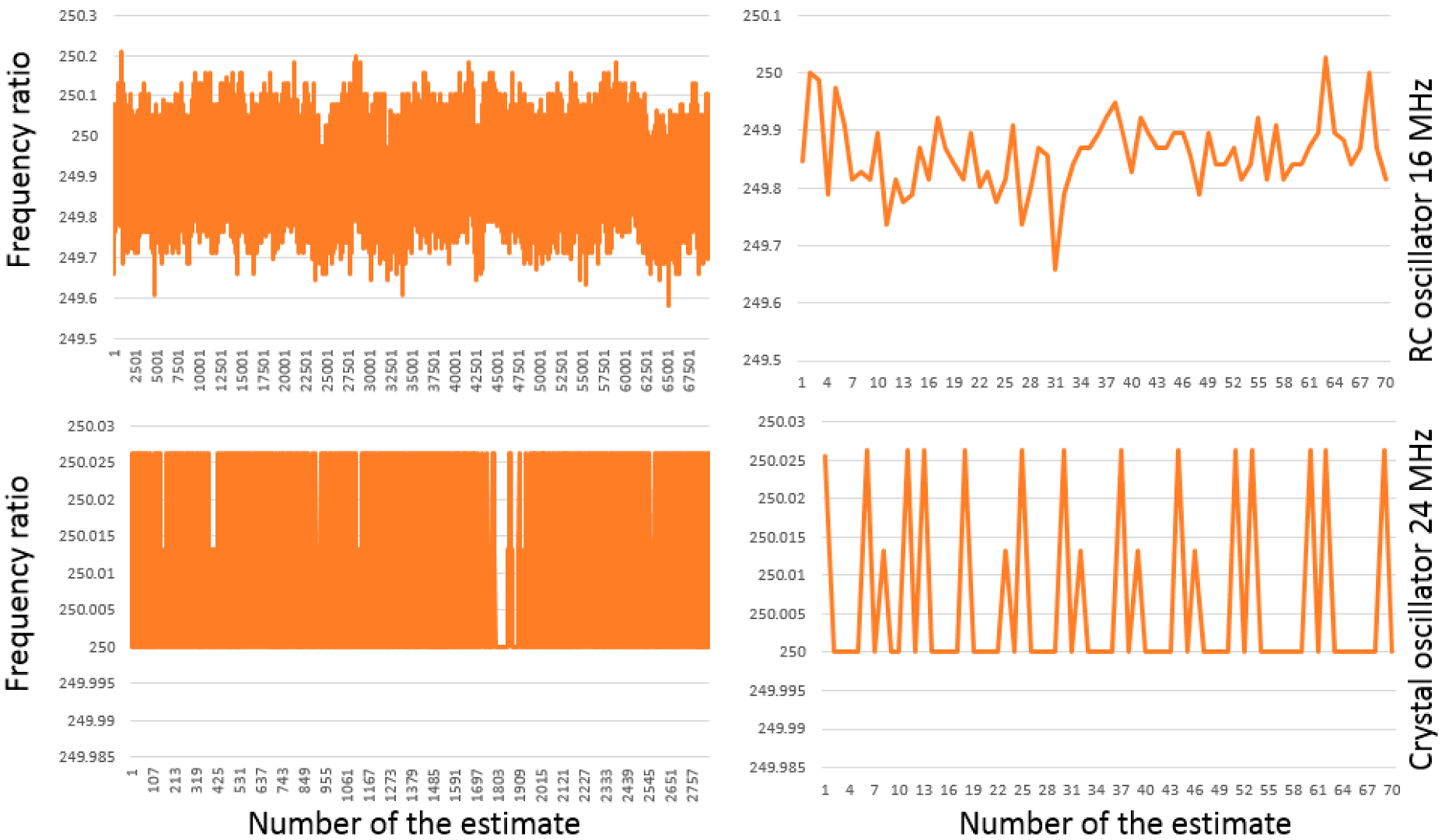
Figure 5 presents measurement results for both primary oscillators.
As expected, pulses derived from the HSI oscillator varied to much greater extent compared to the ones derived from the HSE oscillator. The graph of the HIS estimates resembles some noisy process. In contrast, only three values were captured for the pulses derived from the HSE oscillator, confirming its much higher stability.
Processing of the acquired time series resulted in the numerical estimates of their statistical parameters, presented in Figure 6.
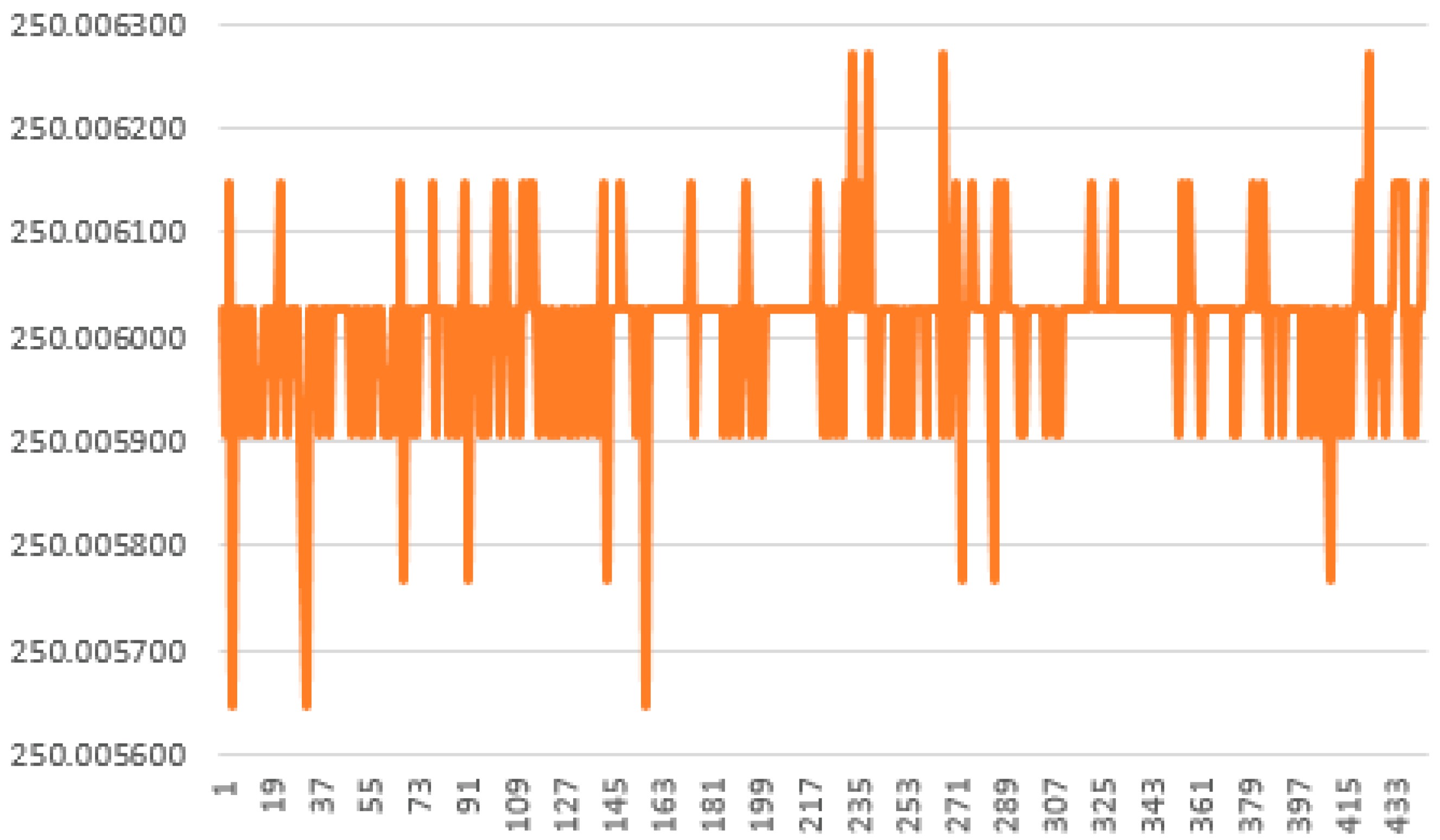
It can be seen that the standard deviation for the HSE-derived pulses, despite being much smaller than that of the HIS-derived pulses, does not correspond well to the specified stability of the crystal oscillators. We attributed this to the insufficient number of averages used and repeated the experiment with 4000 averages instead of 40. The results confirmed that moderate number of averages could be insufficient when evaluating scatter of high-quality frequency sources. The acquired time series is presented in Figure 7 and features only 7 distinct numerical values.
4. Summary and Conclusions
We compared various methods of frequency measurement using timer peripherals of modern MCUs with the purpose of continuously and accurately measuring output frequency of UOTSs.
The required accuracy can be achieved by counting the reference pulses during several periods of the frequency source in question (40 periods were enough for a low stability oscillator but 4000 were required to assess a high stability one). However, this operation is not achievable using a conventional MCU timer’s Capture mode.
Even when using two timers, a continuous stream of frequency estimates is difficult to accomplish because the CPU needs to read the captured values that should be frozen during this time, and the timers are difficult to restart at the very same time.
These inconveniences can be mitigated by employing a timer in the DMA mode, when the captured values are stored in the MCU’s memory without any CPU intervention. The employed STM32D474 MCU could capture values at every edge of the incoming pulses, enabling measurement for every half period of these. The CPU averaged the captured data for the required number of pulses only and communicated the result fully independently.
Verification of the design was conducted using two separate oscillators, low stability RC one and high stability crystal oscillator. The obtained results were as expected.
As the reference pulses are captured for every half-period of the input frequency, it becomes possible to provide continuous stream of moving average estimates of the output frequency of UOTSs. It seems feasible to achieve required accuracy with a conventional crystal oscillator connected to an MCU’s external high-speed oscillator. As the derived timer’s clock frequency can be in the order of 100 MHz, the acceptable number of input signal periods should be in the order of ten. Therefore, a conventional MCU with external crystal seems sufficient to enable continuous accurate moving average measurement of the output frequency of UOTSs.
Author Contributions
Conceptualization, A.N.K.; methodology, A.N.K.; software, A.N.K.; validation, A.E.; formal analysis, A.E.; investigation, A.E.; resources, A.E.; data curation, A.E.; writing—original draft preparation, A.N.K.; writing—review and editing, A.N.K.; visualization, A.E.; supervision, A.N.K.; project administration, A.E.; funding acquisition, A.E. All authors have read and agreed to the published version of the manuscript.
Funding
This research received no external funding.
Institutional Review Board Statement
Not applicable.
Informed Consent Statement
Not applicable.
Acknowledgments
Ali Elyounsi gratefully acknowledges support for his PhD studies from the Libyan Embassy (UK).
Conflicts of Interest
The authors declare no conflict of interest.
References
- Elyounsi, A.; Kalashnikov, A.N. Using Ultrasonic Oscillating Temperature Sensors (UOTSes) to Measure Aggregate temperatures in Liquid and Gaseous Media. In Proceedings of the 2021 IEEE UFFC Latin America Ultrasonics Symposium (LAUS), Gainesville, FL, USA, 4–5 October 2021; pp. 1–4. [Google Scholar] [CrossRef]
- Kirianaki, N.V.; Yurish, S.Y.; Shpak, N.O. Smart sensors with frequency output: State-of-the-art and future development. IFAC Proc. Vol. 2000, 33, 37–42. [Google Scholar] [CrossRef]
- Hashmi, A.; Kalashnikov, A.N. Sensor data fusion for responsive high resolution ultrasonic temperature measurement using piezoelectric transducers. Ultrasonics 2019, 99, 105969. [Google Scholar] [CrossRef] [PubMed]
- Van Ess, D. PSoC1 Measuring Frequency, Application Note AN2283. Available online: https://tinyurl.com/2dpude7s (accessed on 8 December 2022).
- Kirianaki, N.V.; Yurish, S.Y.; Shpak, N.O. Methods of dependent count for frequency measurements. Measurement 2001, 29, 31–50. [Google Scholar] [CrossRef]
- STM32 Cross-Series Timer Overview, Application Note AN4013. Available online: https://tinyurl.com/25f3v9tv (accessed on 8 December 2022).
- INPUT CAPTURE Using DMA||Measure High Frequencies and Low Width, Educational Video. Available online: https://www.youtube.com/watch?app=desktop&v=qqzZ9C0umQ4 (accessed on 8 December 2022).
- Input Capture Using the DMA, Github Repository. Available online: https://tinyurl.com/4wpsb7fc (accessed on 8 December 2022).
- How to Optimize STM32 MCUs Internal RC Oscillator Accuracy, Application Note AN5067. Available online: https://tinyurl.com/tb56h9ta (accessed on 8 December 2022).
- Datasheet C4550, Vectron International. Available online: https://www.vectron.com/products/ocxo/C4550.pdf (accessed on 8 December 2022).
Figure 1.
Gated counter for measuring frequency.

Figure 2.
Waveforms illustrating various methods for frequency measurement waveforms.

Figure 3.
Measuring frequency using built-in timers ((a)—unlinked timers, (b)—externally linked timers, (c)—internally linked timers, (d)—timer in the DMA mode.)
Figure 3.
Measuring frequency using built-in timers ((a)—unlinked timers, (b)—externally linked timers, (c)—internally linked timers, (d)—timer in the DMA mode.)

Figure 4.
Frequency measurement verification setup.

Figure 5.
Measured ratios / for 40 periods of (100 ms delay between measurements).

Figure 6.
Statistical parameters of the acquired time series.

Figure 7.
Measured ratios / for 4000 periods of derived from the 24 MHz crystal oscillator (100 ms delay between consecutive measurements).
Figure 7.
Measured ratios / for 4000 periods of derived from the 24 MHz crystal oscillator (100 ms delay between consecutive measurements).

Publisher’s Note: MDPI stays neutral with regard to jurisdictional claims in published maps and institutional affiliations. |
© 2022 by the authors. Licensee MDPI, Basel, Switzerland. This article is an open access article distributed under the terms and conditions of the Creative Commons Attribution (CC BY) license (https://creativecommons.org/licenses/by/4.0/).
Share and Cite
MDPI and ACS Style
Elyounsi, A.; Kalashnikov, A.N. Continuous Rapid Accurate Measurement of the Output Frequency of Ultrasonic Oscillating Temperature Sensors. Eng. Proc. 2022, 27, 56. https://doi.org/10.3390/ecsa-9-13340
AMA Style
Elyounsi A, Kalashnikov AN. Continuous Rapid Accurate Measurement of the Output Frequency of Ultrasonic Oscillating Temperature Sensors. Engineering Proceedings. 2022; 27(1):56. https://doi.org/10.3390/ecsa-9-13340
Chicago/Turabian StyleElyounsi, Ali, and Alexander N. Kalashnikov. 2022. "Continuous Rapid Accurate Measurement of the Output Frequency of Ultrasonic Oscillating Temperature Sensors" Engineering Proceedings 27, no. 1: 56. https://doi.org/10.3390/ecsa-9-13340