Article

Design Method of Acoustic Metamaterials for Negative Refractive Index Acoustic Lenses Based on the Transmission-Line Theory

Graduate School of Science and Engineering, Kagoshima University, 1-20-40 Korimoto, Kagoshima-shi, Kagoshima 890-0065, Japan
*
Authors to whom correspondence should be addressed.
Crystals 2022, 12(11), 1655; https://doi.org/10.3390/cryst12111655
Submission received: 26 September 2022 / Revised: 14 November 2022 / Accepted: 14 November 2022 / Published: 17 November 2022

Abstract

:
The design theory for electromagnetic metamaterials with negative refractive indices by using a distributed transmission-line model is introduced to the design of acoustic metamaterials, and a negative refractive index (NRI) acoustic lens is designed theoretically. Adjustments to the negative refractive indices of metamaterials have been carried out by calculations with numerical simulators in conventional design methods. As the results show, many calculations are needed to determine the shape of the unit structures and there are issues in that it is difficult to design those rigorously, meaning that limitations regarding the degree of freedom in the designs are many. On the other hand, the transmission-line model can rigorously design the unit cell structures of both the negative refractive index metamaterials and the background media with the positive refractive indices by calculations with the design formulas and modifying the error from the theory with a small calculation. In this paper, a meander acoustic waveguide unit cell structure is proposed in order to realize a structure with characteristics equivalent to the model, and the waveguide width and length for realizing an NRI acoustic lens are determined from the design formula of the model. The frequency dispersion characteristics of the proposed structure are also computed by eigenvalue analysis and the error in the waveguide length from the theoretical value is modified by a minor adjustment of the waveguide length. In addition, the NRI acoustic lens is constituted by periodically arranging the proposed unit cell structure with the calculated parameters, and the full-wave simulations are carried out to show the validity of the design theory. The results show that the designed lens operates at 2.5 kHz.

1. Introduction

Acoustic metamaterials are artificial materials composed of unit cell structures whose sizes are sufficiently smaller than the wavelength and can achieve unique physical phenomena. For example, negative refractive index materials to be applied to negative refractive index (NRI) acoustic lens [1,2,3,4,5,6,7,8,9,10,11,12,13,14,15], acoustic cloaks for hiding objects [4,16,17,18,19,20,21,22], and acoustic illusion media for mimicking arbitrary objects [23,24] have been proposed and studied widely. If we want to realize negative refractive indices, we must design acoustic metamaterials in which both the mass density and the bulk modulus become negative. Resonance structures [1,2,3,4,5,6,7,8,9,10,11,12,13,14,15] have often been adopted as the unit cell structures of NRI acoustic metamaterials in the conventional design methods. To realize negative refractive indices based on those methods, adjustments of the structural parameters such as the widths, lengths, heights, or unit lengths have been required and we can carry those out by calculations with numerical simulators. However, these require greater computational resources, and therefore it is difficult to design unit cell structures rigorously and there are many limitations regarding the degree of freedom in the designs.
We paid attention to the design methods of electromagnetic metamaterials to overcome the issues in the designs of NRI acoustic metamaterials. Transmission-line models with lumped elements and unit cell structures based on those models are often used to realize metamaterials with negative (or zero) refractive index [25,26,27,28,29] in the field of electromagnetic waves. The reason is that those abstract Maxwell’s equations and can lead to broadband and low-loss properties and physical insights. These can easily design NRI metamaterials based on physical insights, but many calculations for determining the structural parameters are required since there are resonance circuit elements. Recently, the distributed transmission-line models have been proposed [30,31,32] to solve the problems in the design methods based on transmission-line models including lumped elements. The model has first been applied to the design of full-tensor anisotropic electromagnetic metamaterials based on transformation electromagnetics [30,31] and it has been demonstrated that we can uniquely determine the line width and length of the unit cell structures by using design formulas without requiring many calculations with numerical simulators. Furthermore, the model has been adopted for the design of NRI electromagnetic metamaterials [32], the validity has been shown through the design of an NRI electromagnetic lens and the analysis by circuit simulations. At the time, we believed that we would be able to solve conventional issues in the designs of NRI acoustic metamaterials if we could introduce this design method for NRI electromagnetic metamaterials to NRI acoustic metamaterials. In the field of acoustic waves, some methods based on the transmission-line theory have already been introduced to designs of acoustic metamaterials because there is the duality between the acoustic equations and Maxwell’s equations [33,34,35,36,37,38]. However, lumped element circuit models are often used for their designs and many calculations requiring numerical simulators become issues. Other transmission-line type structures also do not have design formulas relating to structural parameters of unit cell structures.
In this paper, we introduce the design method with the distributed transmission-line model for NRI electromagnetic metamaterials to NRI acoustic metamaterials, and we show that we can design those by determining the structural parameters of the unit cell structures from the design formulas and modifying the error from the theoretical value with a little calculation. As an example, an NRI acoustic lens is designed based on the introduced method and the operation is confirmed by full-wave simulations. In Section 2, the design theory of the distributed transmission-line model is first recalled [30], and the design formulas with materials’ parameters concerning acoustic waves are shown to determine the structural parameters for NRI acoustic metamaterials. Furthermore, a proposed meander acoustic waveguide unit cell structure for NRI acoustic metamaterials and a straight acoustic waveguide unit cell structure for background media are shown, and the waveguide widths and lengths for realizing an NRI acoustic lens are theoretically determined from the design formulas. In addition, those frequency dispersion characteristics are calculated by eigenvalue analysis with COMSOL, and those waveguide lengths are optimized from the theoretical waveguide lengths with a small number of calculations. In Section 3, the results of the full-wave simulation are presented to show the validity of the design and it is confirmed that a focus and a refocus are generated at those theoretical positions by the designed lens. In Section 4, this paper is concluded.

2. Methods

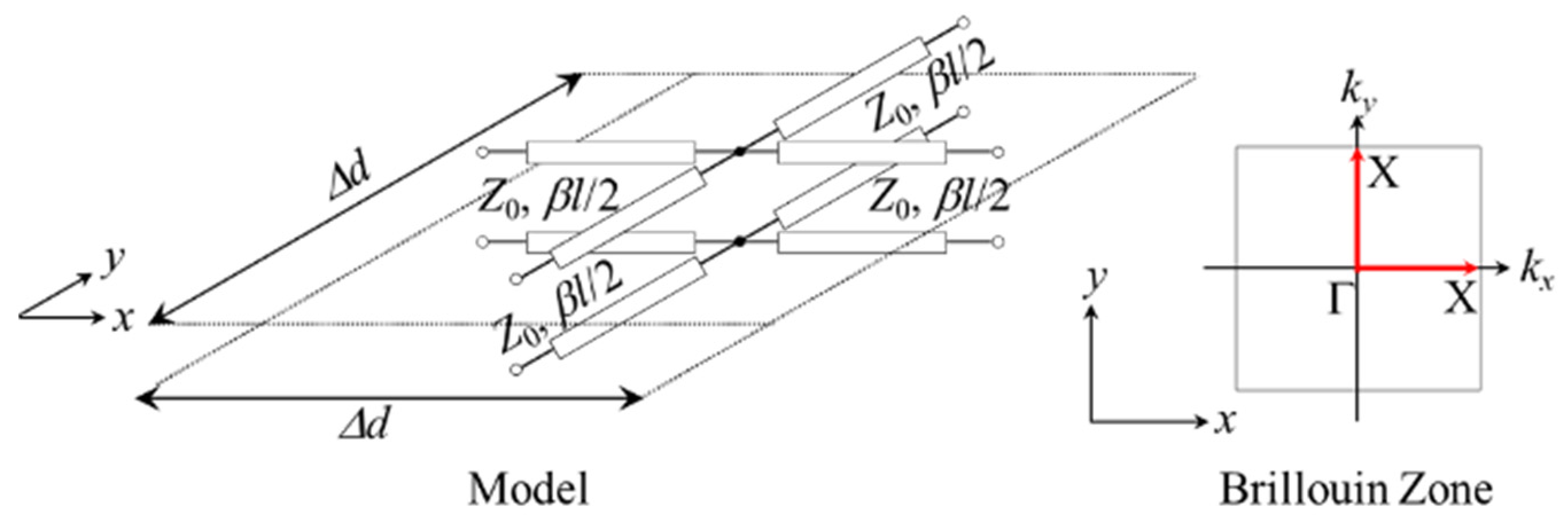
2.1. Distributed Transmission-Line Model and the Design Theory

Figure 1 shows a distributed transmission-line model [16] for the design of negative refractive index metamaterials. Δd, Z0, β, and l are the unit cell length, the characteristic impedance, the phase constant, and the line length, respectively, and βl means the electrical length. If we define the phase constant as β = ω ρ / K , we can apply the design theory of the model to the design of negative refractive index acoustic metamaterials, where ρ and K represent the mass density and the bulk modulus, respectively.
The dispersion characteristics of the model can be calculated from the following formula [28,29,32]:
( e j k x Δ d 1 ) 2 e j k x Δ d + ( e j k y Δ d 1 ) 2 e j k y Δ d + 8 sin 2 β l 2 = 0
k = k x 2 + k y 2
This can be obtained by defining a 4-port ABCD-matrix and solving the eigenvalue problem with Bloch–Floquet periodic boundary conditions [28,29,32]. kx and ky show the wavenumbers in the x and y directions, respectively. Additionally, the formulas for the dispersion characteristics along the Γ-X path, that is represented with the red arrows ((kx = k and ky = 0 or ky = k and kx = 0)), and the refractive index (n) can be written as:
k Δ d = cos 1 ( 1 4 sin 2 β l 2 )
n = c ω Δ d cos 1 ( 1 4 sin 2 β l 2 )
where c and ω are the sound velocity and the angular frequency, respectively. It is noted that the refractive index is defined as the quantity compared with that of the vacuum for the case with electromagnetics, but the refractive index for the case with acoustics do not possess the defined quantity. However, we can define it ourselves by selecting the value of c of the materials that become the standard [1,2,3,4,5,6,7,8,9,10,11,12,13,14,15,33,34,35,36,37,38]. Then, the refractive index becomes negative when the arc cosign in (4) becomes negative, and therefore the condition for the refractive index to be negative is as follows:
1 2 π ( 4 m 1 ) < β l < 2 π m     ( m = 1 ,   2 ,   3 , )
Furthermore, the line length in this case can be calculated from the following formula:
l = c ω ( cos 1 1 + cos ω c n Δ d 2 + 2 π m )     ( m = 1 ,   2 ,   3 , )
It is noted that we need to set the line length to be longer than the unit cell length (l > Δd) when we want to set the operation frequency of the NRI acoustic metamaterials to the region in which the wavelength becomes longer than Δd. The reason is that the propagation modes for negative refractions correspond to the higher modes [32]. Thus, a meander acoustic waveguide unit cell structure is required to realize the model.
The formula of the Bloch impedance for impedance matching in the x or y direction is
Z Bloch = Z 0 2 cos β l cos 2 β l 2
Additionally, this can be obtained by providing the periodic boundary conditions for the models and solving the circuit equations [32]. Incidentally, the relation among those electrical lengths (βBlB and βNRIlNRI) becomes:
β B l B = 2 π β NRI l NRI     ( m = 1 )
when the refractive index of the background medium (nB) agrees with the absolute value of that of the negative refractive acoustic metamaterial (|nNRI|). In this case, we can solve the impedance matching problem if we choose those characteristic impedances (Z0_B and Z0_NRI) to the same value since those Bloch impedances (ZBloch_B and ZBloch_NRI) become the same value automatically from (7).

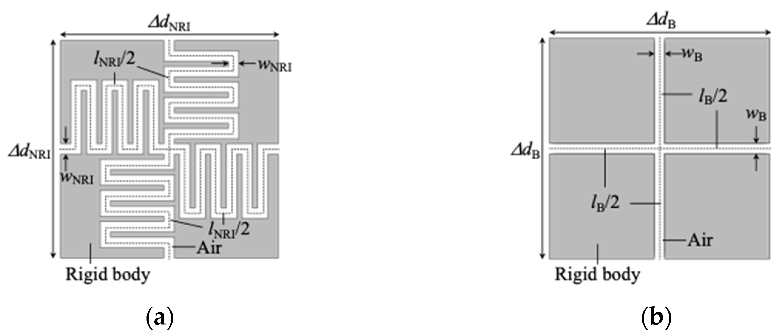
2.2. Proposed Structure

Figure 2a,b shows the proposed meander acoustic waveguide unit cell structure for NRI acoustic metamaterials and the straight acoustic waveguide unit cell structure for background media, respectively. These acoustic waveguides are formed in an ideal rigid body and filled with air (β = βAir, c = cAir), and the wall surfaces in the acoustic waveguides are set to the sound hard boundary in the simulation with COMSOL of the following subsection. The boundary corresponds to the Neumann boundary condition that is the same as the perfect magnetic conductor for the TE incidence case in the analysis of electromagnetic waves, and the wall’s impedance is the set to infinity in this case. lNRI and lB are the waveguide lengths and ΔdNRI and ΔdB (=ΔdNRI = lB) represent the unit cell lengths, and these correspond to the line length and the unit cell length of the model in Figure 1. wNRI and wB are the waveguide widths and these can be used to adjust the characteristic impedance for impedance matching between the NRI acoustic metamaterials and the background medium. Figure 3 shows the concept of an NRI acoustic lens. nNRI and nB are the refractive indices, θB_i and θNRI_i the incident angles, θB_r and θNRI_r the refractive angles, d1 is the distance between the acoustic wave source and the focus, and d2 is the distance between the focus and the refocus. In Figure 3, these parameters are assumed as |nNRI| = nB, θB_i = |θNRI_r| = θNRI_i = |θB_r|, and d2 = d1 in order to simplify the design. We determine the structural parameters in Figure 2 for constituting the NRI acoustic lens and the background medium of Figure 3 in the following.

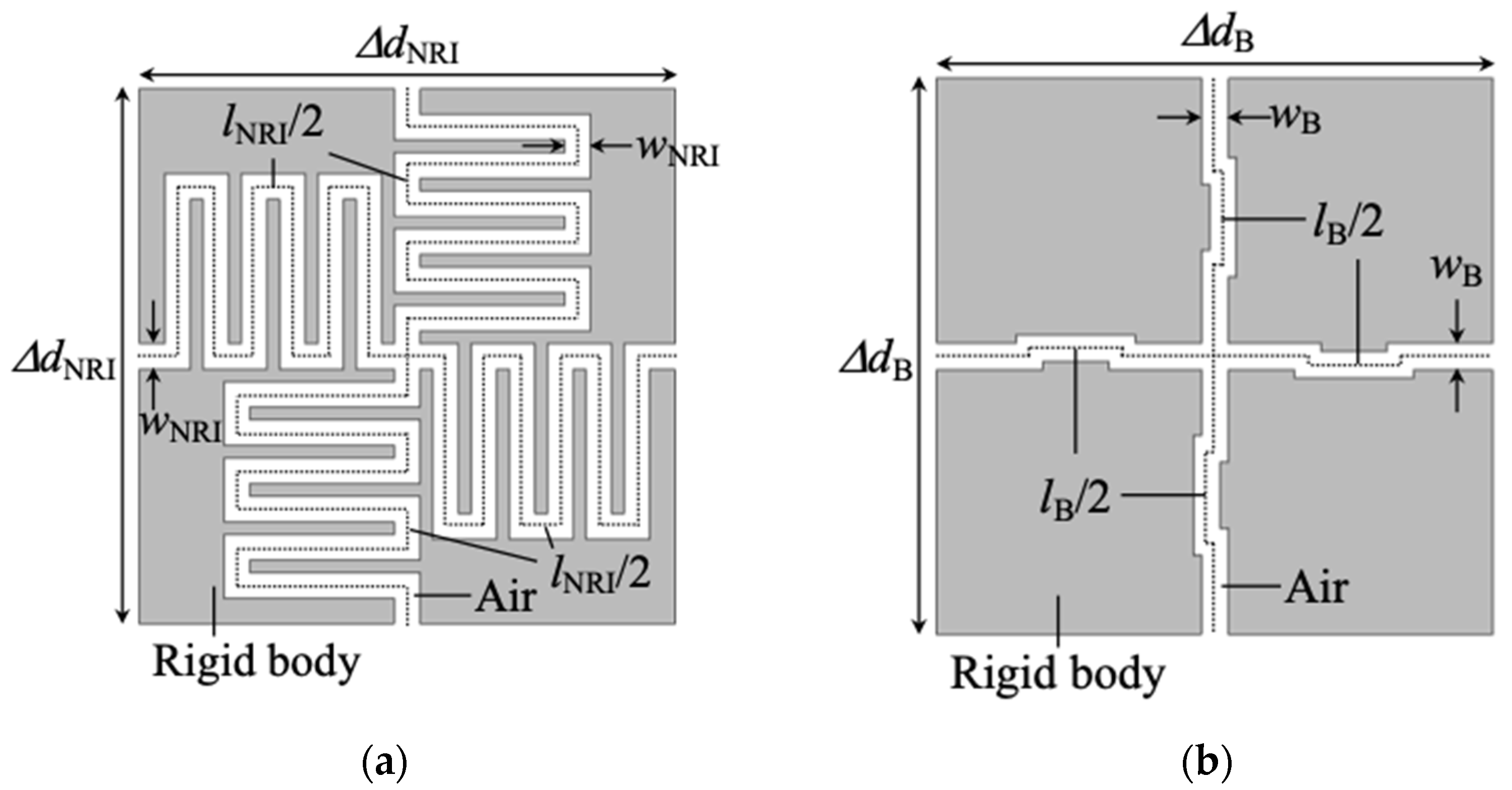
2.3. Acoustic NRI Lens Design

We first set the waveguide length in Figure 2b and the operating frequency of the NRI acoustic lens to lB = ΔdB = ΔdNRI = 25 mm and fNRI = 2.5 kHz, respectively, for feasibility. Additionally, we defined the refractive indices as the quantities compared with the air, and obtained the refractive index of the background medium as nB =1.522 from (4) and determined that of the lens as nNRI = –1.522 from the condition of |nNRI| = nB. Then, we decided the waveguide length in Figure 2a to be lNRI = 113.5 mm by substituting fNRI and nNRI for (6) with m = 1. Moreover, we chose the waveguide widths as wNRI = 1.2 mm and wB = 1.2 mm for considering the feasibility. In this case, impedance matching is also considered and Z0_B = Z0_NRI and ZBloch_B = ZBloch_NRI are held based on (7). Incidentally, the mass density of the lens and the background medium become −4.038 × 10² and 4.038 × 10² kg/mm3 and those bulk moduli become −2.092 × 10⁻² and 2.092 × 10⁻² GPa, respectively. These can be obtained from (4) and (7).
Next, we carried out eigenvalue analysis with COMSOL and calculated the frequency dispersion characteristics along the Γ-X path for the unit cell structures in Figure 2a,b. The results are shown in Figure 4a, and the black solid and broken lines represent the theoretical values of Figure 2a,b calculated from (3), respectively, and the red and blue dots represent their simulated values. Additionally, the intersection of the solid line and the broken one corresponds to the operating frequency of the NRI acoustic lens. Then, the modes of 1–5 correspond to those in Figure 4b and the mode 1’ corresponds to that in Figure 4c. The distributions of instantaneous values of the sound pressure in the acoustic waveguides are shown in the figure. The propagation direction is assumed to x direction (k = kx and ky = 0). Modes 1 and 1’ are the lowest modes and those phases only vary in the x direction. Modes 2 and 4 are known as flat band [6,14,35]. Modes 3 and 5 are identical higher modes and acoustic waves propagate in the x direction while those resonate with one wavelength in y direction. Additionally, the refractive indices become the negative and positive because the slopes are the negative and positive, respectively.
It is seen from Figure 4a that the frequency of the intersection of the simulated results is slightly higher than the theoretical ones. The reason is that the effects of the junction in the center of those structures or the bent waveguides in Figure 2a are not considered in the design values by the models. Therefore, we changed those waveguide lengths. Figure 5a,b shows the adjusted unit cell structures for the NRI acoustic lens and the background medium, respectively. The waveguide lengths are selected as lNRI = 120.36 mm and lB = 26.47 mm, and we determined those with the small number of calculations by using the parametric sweep function of COMSOL. The frequency dispersion characteristics are drawn in Figure 4a with the orange and green dots, respectively. It can be seen from the figure that the frequency of the intersection of those dots agrees with the theoretical model. Incidentally, the NRI lens operates by exciting the mode 3 with the mode 1’. It has also been confirmed by the references of [6,8,9,14,15,35,36] that the higher modes operating as the lens are excited by the lower modes of other structures or materials.
We constitute the NRI acoustic lens and the background medium with the unit cell structures in Figure 5a,b, respectively, and confirm the operation of the lens by a full-wave simulation in the next section.

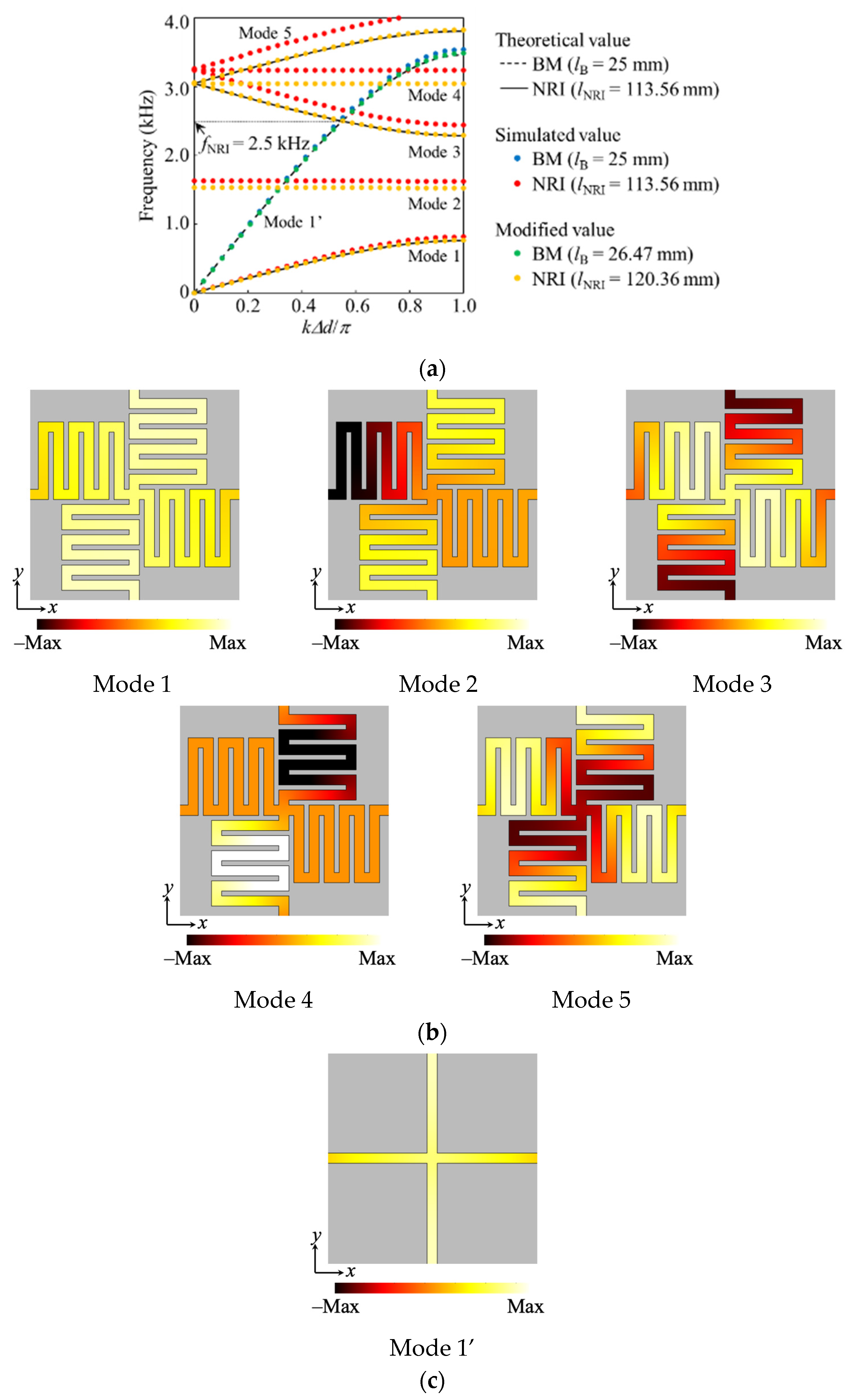
3. Results and Discussion

Figure 6 shows the setup for the full-wave simulation of the designed NRI acoustic lens. The size of the background medium and the lens are selected to be 20ΔdNRI × 5ΔdNRI = 500 mm × 125 mm, and the lens is sandwiched between two background media. Additionally, the background medium and the lens are composed of the structures in Figure 5a,b, respectively. An acoustic wave source is placed at the position where is separated by d1/2 = d2/2 = 2.5ΔdNRI = 62.5 mm (2.5 cell) from the lens. The nodes on all boundaries are set to the sound absorption boundary to perfectly suppress reflected waves. Under the conditions above, we calculated the complex sound pressure distributions in the acoustic waveguide by using COMSOL.
Figure 7a,b shows the calculation the amplitude and the phase distributions of the sound pressure, respectively, and the frequency is set to 2.5 kHz which is the operating frequency of the lens. The wavelength is λ = 3.92ΔdNRI = 98.0 mm and the broken line represents the typical theoretical trajectory of the incident acoustic wave from the source. The intersection of the line in the area of the designed NRI acoustic lens represents the theoretical position of the focus and that in the area of the right-hand side background medium represents the theoretical position of the refocus.
It can be seen from the result that the incident acoustic wave from the source propagates along the theoretical trajectory and the absolute value of the incident angle and the refraction angle agrees well. Then, the focus is formed in the center position of the designed NRI lens, and the position agrees well with the theoretical one. The refocus is also generated to the theoretical position that is separated by 2.5 cells from the lens, and the amplitude is hardly attenuated from that of the acoustic wave source since the impedances of the background medium and the lens agree well with each other. Furthermore, it can be seen that some concentrations of the sound pressure can be generated on the boundary between the background medium and the lens. This corresponds to a plasmonic surface wave at the interface of the positive and the negative media and has been reported in the field of electromagnetic metamaterials [29,39,40,41] as the unique physical phenomenon of NRI lenses that are placed between two positive refractive index media. As is the case with the field of acoustics, the surface wave has been reported in references [9,42,43,44], and the propagating wave and the evanescent wave interact at the focus and the refocus when the distance between the source and the lens is near. In the results of Figure 7, values of the sound pressure between the focus and the refocus become large, and therefore it is considered that those waves interact.
From the results above, it can be concluded that the operation of the designed NRI acoustic lens and the validity of the design method extended from that of the case of NRI electromagnetic metamaterials have been demonstrated.

4. Conclusions

The design theory with the distributed transmission-line model for NRI electromagnetic metamaterials has been introduced to the design of NRI acoustic metamaterials. A meander acoustic waveguide unit cell structure has been proposed to realize the same characteristics as the model and an NRI acoustic lens has been designed using that. The waveguide length and width have been determined based on the theory of the model and the error of the waveguide length from the theoretical value by the effect of the bent waveguide has been modified with eigenvalue analysis. A full-wave simulation has been carried out and the complex sound pressure distributions in the acoustic waveguide have been calculated. The results have shown that the NRI acoustic lens operates at 2.5 GHz and the focus and the refocus are generated to those theoretical positions. Therefore, it has been concluded that the proposed design method can rigorously design NRI acoustic metamaterials or lenses without the need for a small calculation by using the design formulas of the transmission-line model and theoretically determining the structural parameters, such as the waveguide width and length.

Author Contributions

Conceptualization, I.T. and T.N.; methodology, I.T. and T.N.; validation, I.T. and T.N.; formal analysis, I.T.; investigation, I.T. and T.N.; writing—original draft preparation, I.T. and T.N.; writing—review and editing, T.N., S.F. and T.W.; project administration, T.N. All authors have read and agreed to the published version of the manuscript.

Funding

This research received no external funding.

Data Availability Statement

Not applicable.

Conflicts of Interest

The authors declare no conflict of interest.

References

  1. Ding, Y.; Liu, Z.; Qiu, C.; Shi, J. Metamaterial with Simultaneously Negative Bulk Modulus and Mass Density. Phys. Rev. Lett. 2007, 99, 093904. [Google Scholar] [CrossRef] [PubMed]
  2. Zhang, S.; Yin, L.; Fang, N. Focusing Ultrasound with an Acoustic Metamaterial Network. Phys. Rev. Lett. 2009, 102, 194301. [Google Scholar] [CrossRef] [PubMed] [Green Version]
  3. Lee, S.H.; Park, C.M.; Seo, Y.M.; Wang, Z.G.; Kim, C.K. Composite Acoustic Medium with Simultaneously Negative Density and Modulus. Phys. Rev. Lett. 2010, 104, 054301. [Google Scholar] [CrossRef] [PubMed]
  4. Zhu, X.; Liang, B.; Kan, W.; Zou, X.-Y.; Cheng, J. Acoustic Cloaking by a Superlens with Single-Negative Materials. Phys. Rev. Lett. 2011, 106, 014301. [Google Scholar] [CrossRef]
  5. Zhu, J.; Christensen, J.; Jung, J.; Martin-Moreno, L.; Yin, X.; Fok, L.; Zhang, X.; Garcia-Vidal, F.J. A holey-structured metamaterial for acoustic deep-subwavelength imaging. Nat. Phys. 2010, 7, 52–55. [Google Scholar] [CrossRef] [Green Version]
  6. Liu, F.; Huang, X.; Chen, C.T. Dirac cones at k = 0 in acoustic crystals and zero refractive index acoustic meterials. Appl. Phys. Lett. 2012, 100, 071911. [Google Scholar] [CrossRef] [Green Version]
  7. Cheng, Y.; Zhou, C.; Wei, Q.; Wu, D.; Liu, X. Acoustic subwavelength imaging of subsurface objects with acoustic resonant metalens. Appl. Phys. Lett. 2013, 103, 224104. [Google Scholar] [CrossRef]
  8. Hladky-Hennion, A.-C.; Vasseur, J.O.; Haw, G.; Croënne, C.; Haumesser, L.; Norris, A.N. Negative refraction of acoustic waves using a foam-like metallic structure. Appl. Phys. Lett. 2013, 102, 144103. [Google Scholar] [CrossRef] [Green Version]
  9. Zhou, X.; Assouar, M.B.; Oudich, M. Acoustic superfocusing by solid phononic crystals. Appl. Phys. Lett. 2014, 105, 233506. [Google Scholar] [CrossRef] [Green Version]
  10. Su, H.; Zhou, X.; Xu, X.; Hu, G. Experimental study on acoustic subwavelength imaging of holey-structured metamaterials by resonant tunneling. J. Acoust. Soc. Am. 2014, 135, 1686–1691. [Google Scholar] [CrossRef]
  11. Park, J.J.; Park, C.M.; Lee, K.J.B.; Lee, S.H. Acoustic superlens using membrane-based metamaterials. Appl. Phys. Lett. 2015, 106, 051901. [Google Scholar] [CrossRef]
  12. Yang, X.; Yin, J.; Yu, G.; Peng, L.; Wang, N. Acoustic superlens using Helmholtz-resonator-based metamaterials. Appl. Phys. Lett. 2015, 107, 193505. [Google Scholar] [CrossRef]
  13. Kaina, N.; Lemoult, F.; Fink, M.; Lerosey, G. Negative refractive index and acoustic superlens from multiple scattering in single negative metamaterials. Nature 2015, 525, 77–81. [Google Scholar] [CrossRef] [PubMed]
  14. Dubois, M.; Shi, C.; Zhu, X.; Wang, Y.; Zhang, X. Observation of acoustic Dirac-like cone and double zero refractive index. Nat. Commun. 2017, 8, 14871. [Google Scholar] [CrossRef]
  15. Chen, M.; Jiang, H.; Zhang, H.; Li, D.; Wang, Y. Design of an acoustic superlens using single-phase metamaterials with a star-shaped lattice structure. Sci. Rep. 2018, 8, 1861. [Google Scholar] [CrossRef] [Green Version]
  16. Cummer, S.A.; Schurig, D. One path to acoustic cloaking. New J. Phys. 2007, 9, 45. [Google Scholar] [CrossRef]
  17. Chen, H.; Chan, C.T. Acoustic cloaking in three dimensions using acoustic metamaterials. Appl. Phys. Lett. 2007, 91, 183518. [Google Scholar] [CrossRef]
  18. Norris, A. Acoustic cloaking theory. Proc. R. Soc. A Math. Phys. Eng. Sci. 2008, 464, 2411–2434. [Google Scholar] [CrossRef]
  19. Torrent, D.; Sánchez-Dehesa, J. Acoustic cloaking in two dimensions: A feasible approach. New J. Phys. 2008, 10, 063015. [Google Scholar] [CrossRef] [Green Version]
  20. Zhang, S.; Xia, C.; Fang, N. Broadband Acoustic Cloak for Ultrasound Waves. Phys. Rev. Lett. 2011, 106, 024301. [Google Scholar] [CrossRef]
  21. Zigoneanu, L.; Popa, B.-I.; Cummer, S.A. Three-dimensional broadband omnidirectional acoustic ground cloak. Nat. Mater. 2014, 13, 352–355. [Google Scholar] [CrossRef] [PubMed] [Green Version]
  22. Bi, Y.; Lu, W.; Ji, P.; Yang, J. Design and demonstration of an underwater acoustic carper cloak. Sci. Rep. 2017, 7, 705. [Google Scholar] [CrossRef] [PubMed] [Green Version]
  23. Kan, W.; Liang, B.; Zhu, X.; Li, R.; Zou, X.; Wu, H.; Yang, J.; Cheng, J. Acoustic Illusion near Boundaries of Arbitrary Curved Geometry. Sci. Rep. 2013, 3, 1427. [Google Scholar] [CrossRef] [PubMed] [Green Version]
  24. Kan, W.; Liang, B.; Li, R.; Jiang, X.; Zou, X.-Y.; Yin, L.-L.; Cheng, J. Three-dimensional broadband acoustic illusion cloak for sound-hard boundaries of curved geometry. Sci. Rep. 2016, 6, 36936. [Google Scholar] [CrossRef] [PubMed] [Green Version]
  25. Caloz, C.; Itoh, T. Application of the transmission line theory of left-handed (LH) materials to the realization of a microstrip “LH line”. IEEE Antennas Propag. Soc. Int. Symp. 2002, 2, 412–415. [Google Scholar] [CrossRef]
  26. Oliner, A.A. A periodic-structure negative-refractive-index medium without resonant elements. IEEE AP-S/URSI Int. Symp. Dig. 2002, 41, 10012635372. [Google Scholar]
  27. Eleftheriades, G.; Iyer, A.; Kremer, P. Planar negative refractive index media using periodically L-C loaded transmission lines. IEEE Trans. Microw. Theory Tech. 2002, 50, 2702–2712. [Google Scholar] [CrossRef]
  28. Sanada, A.; Caloz, C.; Itoh, T. Characteristics of the composite right/left-handed transmission lines. IEEE Microw. Wirel. Compon. Lett. 2004, 14, 68–70. [Google Scholar] [CrossRef]
  29. Sanada, A.; Caloz, C.; Itoh, T. Planar Distributed Structures with Negative Refractive Index. IEEE Trans. Microw. Theory Tech. 2004, 52, 1252–1263. [Google Scholar] [CrossRef]
  30. Nagayama, T.; Sanada, A. Planar Distributed Full-Tensor Anisotropic Metamaterials for Transformation Electromagnetics. IEEE Trans. Microw. Theory Technol. 2015, 63, 3851–3861. [Google Scholar] [CrossRef]
  31. Nagayama, T.; Sanada, A. Broadband transmission-line illusions based on transformation electromagnetic. EPJ Appl. Metamater. 2019, 6, 23. [Google Scholar] [CrossRef]
  32. Nagayama, T.; Fukushima, S.; Watanabe, T. Design Method for Negative Refractive Index Metamaterials by Using a Distributed Transmission-Line Model. In Proceedings of the 2020 IEEE International Symposium on Radio-Frequency Integration Technology (RFIT), Hiroshima, Japan, 2–4 September 2020; pp. 58–60. [Google Scholar] [CrossRef]
  33. Fang, N.; Xi, D.; Xu, J.; Ambati, M.; Srituravanich, W.; Sun, C.; Zhang, X. Ultrasonic metamaterials with negative modulus. Nat. Mater. 2006, 5, 452–456. [Google Scholar] [CrossRef] [PubMed]
  34. Bongard, F.; Lissek, H.; Mosig, J.R. Acoustic transmission line metamaterial with negative/zero/positive refractive index. Phys. Rev. B 2010, 82, 094306. [Google Scholar] [CrossRef]
  35. Liang, Z.; Li, J. Extreme Acoustic Metamaterial by Coiling Up Space. Phys. Rev. Lett. 2012, 108, 114301. [Google Scholar] [CrossRef]
  36. Xie, Y.; Popa, B.-I.; Zigoneanu, L.; Cummer, S.A. Measurement of a Broadband Negative Index with Space-Coiling Acoustic Metamaterials. Phys. Rev. Lett. 2013, 110, 175501. [Google Scholar] [CrossRef] [Green Version]
  37. Naify, C.J.; Layman, C.N.; Martin, T.P.; Nicholas, M.; Calvo, D.C.; Orris, G.J. Experimental realization of a variable index transmission line metamaterial as an acoustic leaky-wave antenna. Appl. Phys. Lett. 2013, 102, 203508. [Google Scholar] [CrossRef]
  38. Kim, W.-G.; Kang, H.S.; Jung, K.-I.; Yoon, S.W.; Lee, K.I. Experimental verification of zeroth-order resonance phenomenon in an acoustic composite right/left-handed metamaterial resonator. Jpn. J. Appl. Phys. 2019, 58, 080907. [Google Scholar] [CrossRef]
  39. Pendry, J.B. Negative Refraction Makes a Perfect Lens. Phys. Rev. Lett. 2000, 85, 3966–3969. [Google Scholar] [CrossRef]
  40. Caloz, C.; Sanada, A.; Itoh, T. Surface plasmons at the interface between right-handed and left-handed 2D metamaterials. IEEE AP-S Int. Symp. Dig. 2003, 3, 363–366. [Google Scholar] [CrossRef]
  41. Smith, D.R.; Schurig, D.; Rosenbluth, M.; Schultz, S.; Ramakrishna, S.A.; Pendry, J.B. Limitations on subdiffraction imaging with a negative refractive index slab. Appl. Phys. Lett. 2003, 82, 1506–1508. [Google Scholar] [CrossRef]
  42. Luo, C.; Johnson, S.G.; Joannopoulos, J.D.; Pendry, J.B. Subwavelength imaging in photonic crystals. Phys. Rev. B 2003, 68, 045115. [Google Scholar] [CrossRef] [Green Version]
  43. Veres, I.A.; Berer, T.; Matsuda, O.; Burgholzer, P. Focusing and subwavelength imaging of surface acoustic waves in a solid-air phononic crystal. J. Appl. Phys. 2012, 112, 053504. [Google Scholar] [CrossRef]
  44. Ma, F.; Huang, Z.; Liu, C.; Wu, J.H. Acoustic focusing and imaging via phononic crystal and acoustic metamaterials. J. Appl. Phys. 2022, 131, 011103. [Google Scholar] [CrossRef]
Figure 1. Distributed transmission-line model for the design of NRI acoustic metamaterials. The red arrows show the Γ-X pass (kx = k and ky = 0 or ky = k and kx = 0) in the Brillouin Zone.
Crystals 12 01655 g001
Figure 2. Unit cell structures. (a) Proposed meander acoustic waveguide unit cell structure for NRI acoustic metamaterials; (b) Straight acoustic waveguide unit cell structure for background media.
Crystals 12 01655 g002
Figure 3. The concept of an NRI acoustic lens. |nNRI| = nB, θB_i = |θNRI_r| = θNRI_i = |θB_r|, d2 = d1 are assumed in this figure.
Crystals 12 01655 g003
Figure 4. Calculated frequency dispersion characteristics for the NRI acoustic lens and the background medium (BM) at the Γ-X pass (k = kx and ky = 0), and modes of acoustic waves in the acoustic waveguide. (a) Dispersion characteristics; (b) Distributions of instantaneous values of the sound pressure of modes of 1–5 in (a); (c) Distributions of instantaneous values of the sound pressure of mode 1’ in (a). The intersection of the solid line and the broken one in (a) corresponds to the operating frequency of the NRI acoustic lens. The propagation direction of (b) assumes x direction.
Crystals 12 01655 g004
Figure 5. Modified unit cell structures. (a) For the NRI acoustic lens (ΔdNRI = 25 mm, wNRI = 1.2 mm, and lNRI = 120.36 mm); (b) For the background medium (ΔdB = 25 mm, wB = 1.2 mm, and lB = 26.47 mm). These refractive indices are set as nNRI = −1.522 and nB = 1.522, respectively.
Crystals 12 01655 g005
Figure 6. The setup for the full-wave simulation for the designed NRI acoustic lens (ΔdB = ΔdNRI = 25 mm). The size of the background medium and the lens are 20ΔdNRI × 5ΔdNRI = 500 mm × 125 mm, and are composed of the structures in Figure 5a,b, respectively. An acoustic wave source is placed at the position where it is separated by d1/2 = d2/2 = 2.5ΔdNRI = 62.5 mm from the lens.
Crystals 12 01655 g006
Figure 7. Calculated complex sound pressure distributions at 2.5 kHz. The wavelength is λ = 3.92ΔdNRI = 98.0 mm. The broken line represents an example of the theoretical trajectory of the incident acoustic wave from the source. The intersection of the line in the area of the designed NRI acoustic lens represents the theoretical position of the focus and that in the area of the right-hand side background medium represents the theoretical position of the refocus. (a) Amplitude; (b) Phase.
Crystals 12 01655 g007
Publisher’s Note: MDPI stays neutral with regard to jurisdictional claims in published maps and institutional affiliations.

