

Direct Ink Writing of Anisotropic Luminescent Materials

1
Materials and Process Engineering, Department of Engineering and Architecture, Università degli studi di Trieste (UniTS), 34127 Trieste, Italy
2
Laboratory of Stimuli-Responsive Functional Materials and Devices (SFD), Department of Chemical Engineering and Chemistry, Eindhoven University of Technology (TU/e), 5600 MB Eindhoven, The Netherlands
*
Author to whom correspondence should be addressed.
Crystals 2022, 12(11), 1642; https://doi.org/10.3390/cryst12111642
Submission received: 26 October 2022
/
Revised: 7 November 2022
/
Accepted: 10 November 2022
/
Published: 16 November 2022
(This article belongs to the Special Issue Advances in Liquid Crystal Optical Devices)
Abstract
:Luminescent solar concentrators are relatively inexpensive devices proposed to collect, convert, and redirect incident (sun)light for a variety of potential applications. In this work, dichroic dyes are embedded in a liquid crystal elastomer matrix and used as feedstock for direct ink writing. Direct ink writing is a promising and versatile application technique for arbitrarily aligning the dichroic dyes over glass and poly(methyl methacrylate) lightguide surfaces. The resulting prints display anisotropic edge emissions, and suggest usage as striking visual objects, combining localized color and intensity variations when viewed through a polarizer.
1. Introduction
Luminescent solar concentrators (LSCs) are devices for collecting, converting, and redistributing sunlight [1,2,3,4,5,6,7], and by combining a straightforward architecture with the ability to control and modify light, have been proposed for use in a wide variety of applications, including as electricity generators [8], for catalyzing chemical reactions [9], enhancing horticultural production [10,11], as switchable “smart” windows [12], and for hydrogen production [13], among others [6]. The basic design consists of a transparent lightguide plate filled or topped with a fluorescent material. Incident (sun)light absorbed by the fluorophore is re-emitted at longer wavelengths, a fraction of this emitted light becoming trapped within the higher refractive index lightguide by total internal reflection, escaping primarily from the edges of the lightguide.
Many organic fluorescent molecules have extended structures with absorption and emission transition dipole moments more-or-less coincident with their molecular axis. This means that, if macroscopically aligned, the dyes absorb specific linear polarizations in preference to others. Likewise, emission of light is similarly expressed more strongly in directions favoring emission perpendicular to the transition dipole moment axes than parallel [14].
Considerable efforts have been directed towards improving the efficiency of LSC devices. One approach involves aligning the luminophore molecules of the LSC homeotropically to reduce photon losses through the surface(s) of the lightguide after the emission process and so increasing the efficiency [15,16,17]. When a suitably dichroic dye is used, it is also possible to direct the emission by aligning the dye planar to the lightguide surface [16,18,19,20]: by directing a significant fraction of the emitted light towards two rather than four edges, it will be possible to deploy two rather than four photovoltaics on the most radiant edges, reducing the overall cost of the device.
Nematic liquid crystals (LCs) have been used as a host for aligning dichroic organic luminophores due to their self-assembling ability [16,18,19]. Previous work has demonstrated deposition of oriented liquid crystalline elastomers (LCEs) via the additive manufacture technique of direct ink writing (DIW), a microextrusion technique wherein it has been shown that printed LC inks have alignment following the print path [21,22,23]. These alignments have been further verified using the dichroic nature of embedded dyes [24,25]. In this work, we deposit an LCE material embedded with organic fluorescent dyes on two different substrates, glass and PMMA, to generate anisotropic LSC devices. If printing of aligned fluorescent dyes is possible, this would allow for complex optical structures with dye alignments varying over the surface of the device, which could find use in not only LSCs, but also security features or advanced light control elements.
2. Materials and Methods
The basic procedure for producing the LCE involves a thiol-Michael addition reaction described previously [23]. In summary, the LC diacrylate mesogens 2-methyl-1,4-phenylene bis(4-((6-(acryloyloxy)hexyl)oxy)benzoate) (“RM82”) and 2-methyl-1,4-phenylene bis(4-(3-(acryloyloxy)propoxy)benzoate) (“RM257”, both from Merck KGaA) are added in a 1:1:2 molar ratio with the chain extender 2,2′-(ethylenedioxy)diethanethiol (TCI Europe N.V.), and dissolved in dichloromethane (Biosolve) at 4 mL solvent per mg of reactants, in a 250 mL flask. The mix is stirred at room temperature for approximately 90 min before catalyst dimethylphenylphosphine (Sigma-Aldrich) is added. The reaction is rapid [26]; but we left it for about 1 h to ensure the reaction went to completion.
The thermal polymerization inhibitor 2,6-di-tert-butyl-4-methylphenol (0.05 wt%), 2 wt% photoinitiator phenylbis(2,4,6-trimethylbenzoyl)phosphine oxide and 0.05-0.1 wt% of the organic dye DFSB-K160 (“K160”, Risk Reactor Inc.) or 0.05-0.2 wt% 4-(dicyanomethylene)-2-methyl-6-(4-dimethylaminostyryl)-4H-pyran (“DCM”, Sigma-Aldrich) was then added to the solution and mixed 30 min at room temperature. The mix is transferred to a PTFE evaporation dish on a hot plate and left for 90 min at 50 °C, and then placed in a vacuum oven for 30 min at 80 °C to evaporate the remaining solvent. The final material is a sticky LC oligomer, suitable as DIW feedstock.
Ink deposition is accomplished using a Hyrel EHR 3D printer equipped with a TAM-15 high-operating temperature syringe extrusion head with a nozzle diameter of 0.335 mm (Fisnar QuantX Micron-S Red). Squares of 2 × 2 cm2, and 2.5 × 2.5 cm2 are printed on PMMA (50 × 50 × 5 mm3) or glass (30 × 30 × 1 mm3) substrates at printing speeds between 700 to 1000 mm min−1. Bed temperature was RT for the glass substrates and fixed at 30 °C for the PMMA substrates, while the temperature of the syringe is set at 10 °C below the nematic-isotropic transition, TNI, of the ink (usually around 70 °C, sample DSC data may be found in the Supplementary Materials (SM) as Figure S1). After printing, which takes about 1 min, the samples are immediately illuminated with a high-intensity UV lamp (Excelitas EXFO Omnicure S2000) for 15 min on the printed side and 15 min through the rear side to polymerize and form the crosslinked elastomer.
NMR spectra (example spectrum seen as Figure S2 in the Supplementary Materials) were recorded with a Bruker Avance III HD 400 MHz in chloroform-d (purchased from Sigma-Aldrich Inc., 99.8 atom % D, 0.03% v/v tetramethylsilane). Average chain length was determined by comparing the ratio of acrylate to mesogenic core signal [23]. Thermal behavior of the inks was investigated with a TA Instruments DSC Q2000. Polarized absorbances of the samples were recorded using a PerkinElmer Lambda 750 UV-vis-NIR spectrophotometer equipped with an integrating sphere detector and rotating linear polarizer. Surface profiles and thickness of the prints were evaluated using a Sensofar S neox 3D optical profiler. To measure edge emission, samples were illuminated by a 300 W solar simulator (Lot-Oriel) and output from sample edges was measured using a SLMS 1050 integrating sphere (Labsphere) equipped with a diode array detector (RPS900, International Light). A correction was made for the small polarization anisotropy (~10%) of the solar simulator. Internal efficiencies [27,28] were calculated as:
3. Results and Discussion
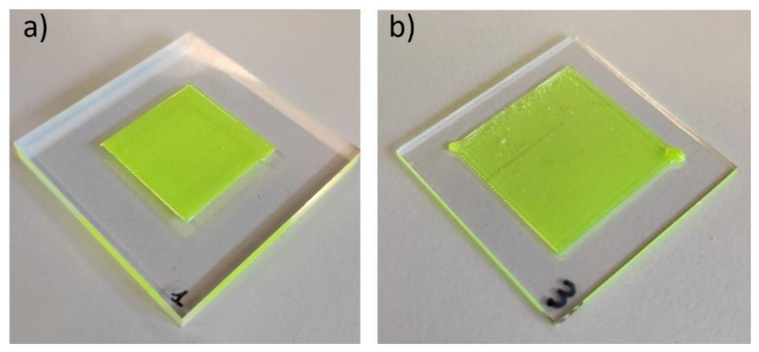
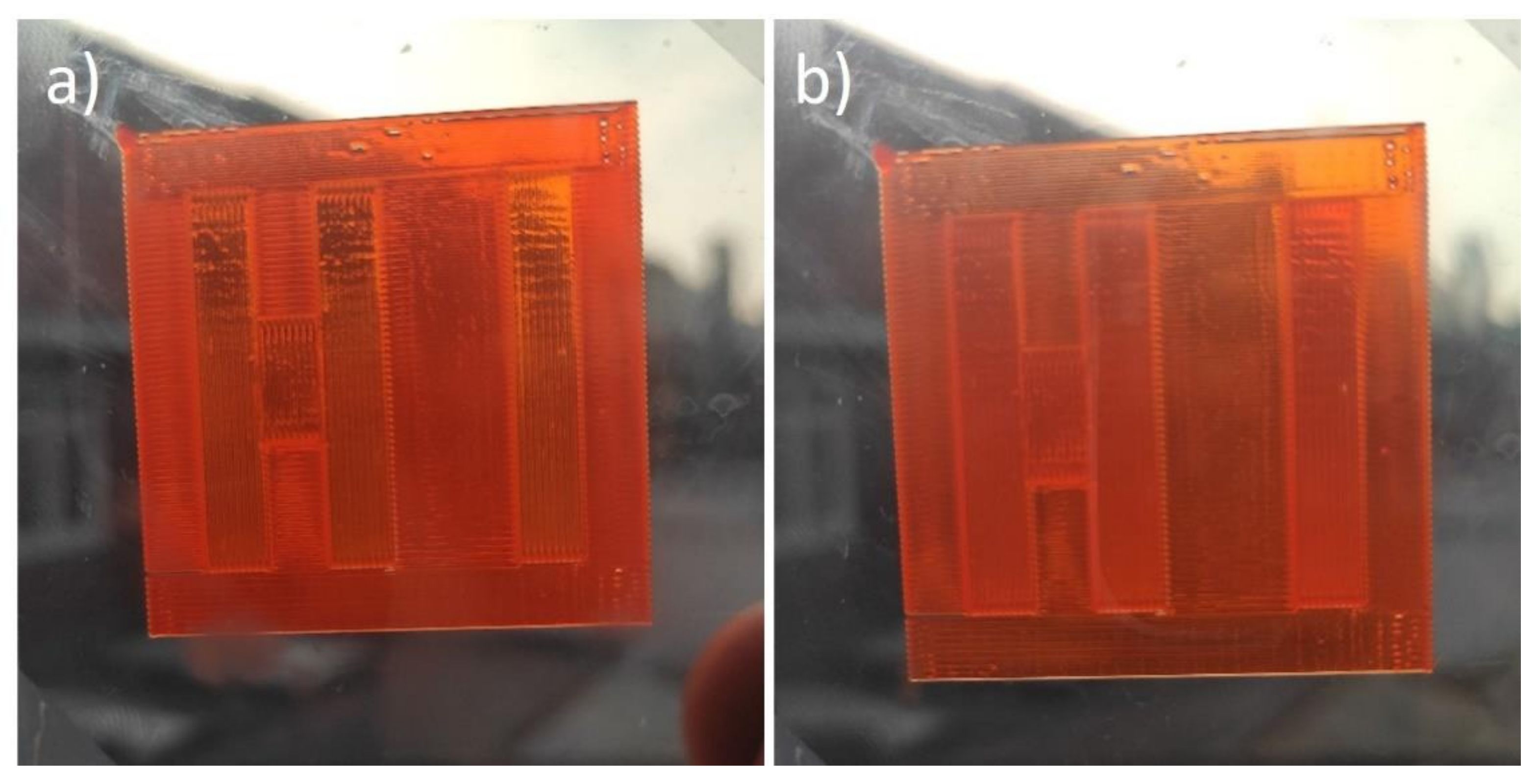
Two commercial fluorescent dyes were used in this work, the orange laser dye DCM and lime-emitting K160. These two dyes have been used previously in spin-coated liquid crystal thin films [18]. The dye-doped oligomeric inks were DIW on both glass and PMMA substrates and photopolymerized to form the elastomers. Examples of K160 samples printed on the two different substrates are shown in Figure 1a,b: no difference in LCE adhesion to either substrate was observed.
The dichroic order parameter, S, a common parameter to describe LC and dye alignments [3,12], of the fluorescent dye in the LC host is determined by measuring the absorption of light polarized along (Apar) and perpendicular (Aper) the direction of the liquid crystal director using:
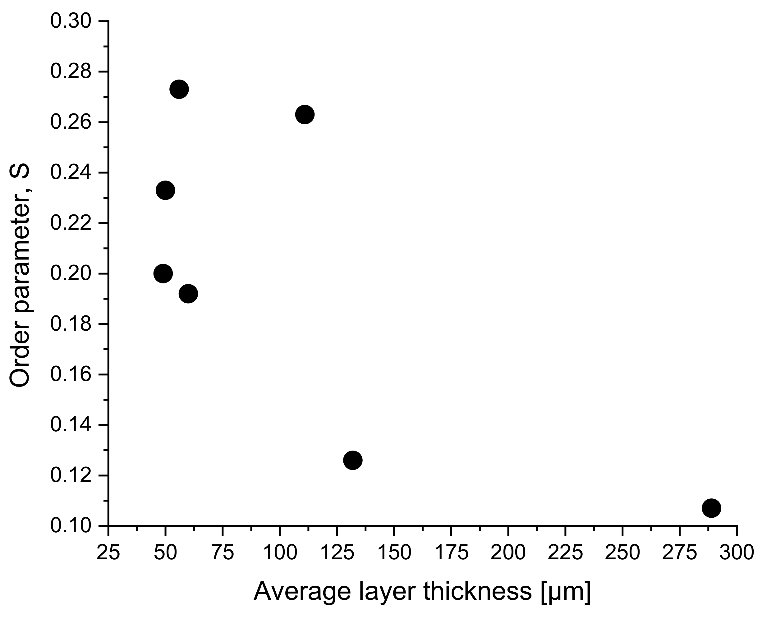
The absorbance values are typically measured in a spectrophotometer equipped with a rotating polarizer (for a sample spectra and appearance of the film under polarized optical microscopy, see Figure S3 in the Supplementary Materials). From previous work using spin-coated LC films on pre-treated substrates, the S-values of the two dyes were roughly 0.25–0.45 for DCM and 0.4–0.57 for K160 [18]. For the extruded material, we generally find lower values for K160 of S = 0.1–0.3 on PMMA, depending on the resulting thickness of the applied layer, as seen in Figure 2, with thinner layers generally displaying greater order (all data may be found in the Supplementary Materials as Table S1). Two samples on glass showed significantly higher order, averaging 0.45. Three 0.2 wt% DCM samples between 75 and 108 μm thick averaged S = 0.18, so somewhat lower than K160, as previously noted [18]. Once printed and photopolymerized, further heating the samples reduced the order, but this loss was reversed upon cooling; see Figure S4 in the Supplementary Materials.
The reduced alignment in the DIW samples as compared to samples previously reported at least partly results from the increased thickness of the DIW written samples compared to spin coated samples; the DIW written samples rely entirely on the shear forces generated during printing for alignment, and typical printed LCEs themselves only have order parameters around S = 0.3 [21,29]. Additionally, the DIW samples demonstrate a more scattered appearance, suggesting reduced order within the deposited stripe. Regardless, the dyes do demonstrate a degree of anisotropic alignment. The advantage of using a DIW process is that aligned dyes may be deposited in almost any pattern at any location over the lightguide surface: this is considerably more complicated to achieve using spin coating, for example. It would also be possible to deposit different dyes over the same surface at discrete locations and deposition directions: while multicolor LSCs have been demonstrated [30,31,32], none have deployed aligned dye materials.
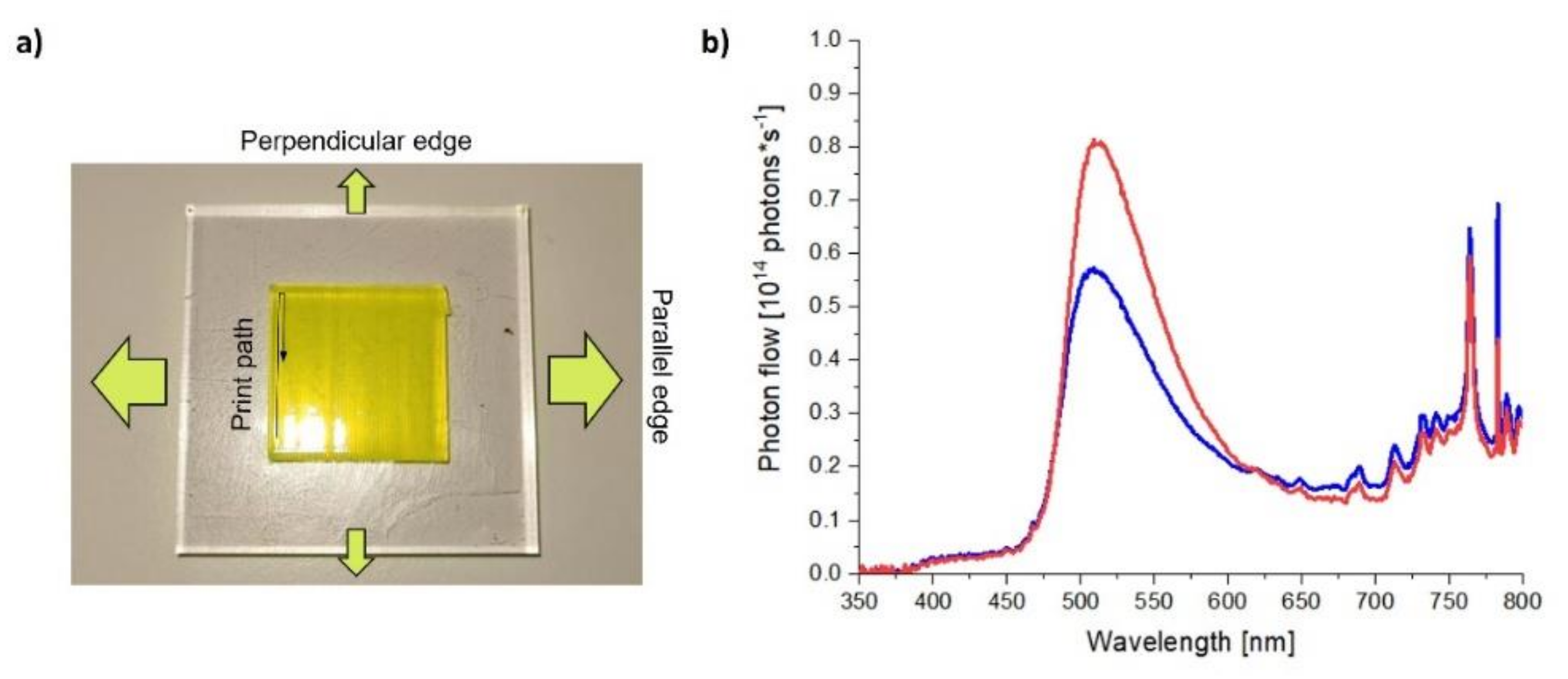
The emission power output was recorded for each of the four edges of the samples. If the deposition direction of the DIW deposition is primarily parallel to the entry port of the integrating sphere it is called “parallel edge”, while if it is perpendicular to the entry port it is called “perpendicular edge”, similar to the earlier definition (see Figure 3a) [18]. Representative spectra obtained from the two edges for one DIW sample are shown in Figure 3b. The edge emission data and calculated internal efficiencies may be found in Table S1 in the Supplementary Materials.
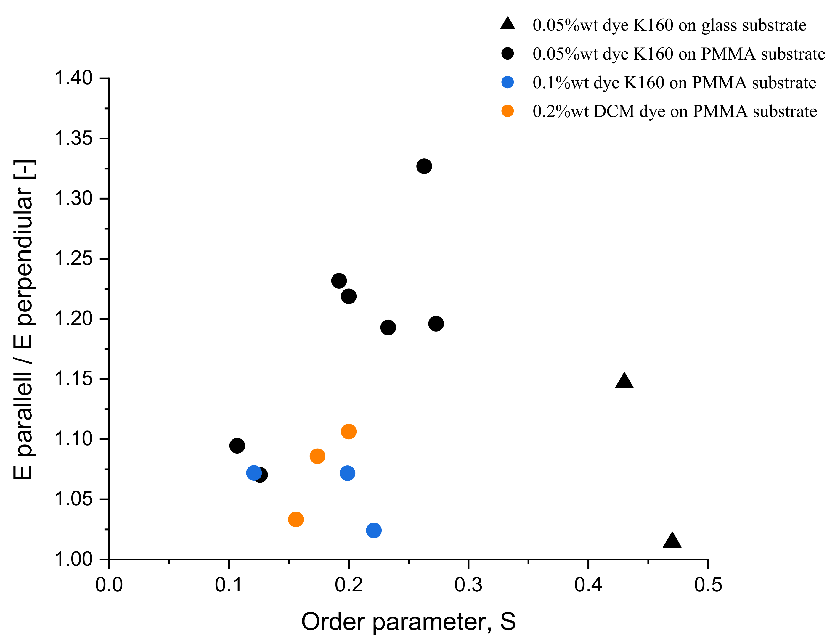
The resulting ratios between the parallel and perpendicular emissions for square samples on both PMMA and glass are plotted in Figure 4. Even though the order parameters obtained are only modest, for each sample the difference in the edge emission is quite discernable. In general, DIW of the oligomers produced considerably more scattering samples than spin-coated LCs. This manifests as additional scatter in the spectra, and readily visible in the somewhat “milky” appearance of the DIW samples. The printed squares also show surface texture from the rounded nature of the printed lines, also a source of scatter. As a result, the dichroism of emission for the DIW samples is considerably lower than that determined for the spin-coated samples [18].
Normally, one might expect better alignment should mean higher emission ratios but does not seem to be the case considering the glass samples (Figure 4 and Table S1 in the Supplementary Materials). We believe the diminished performance of the glass lightguides is a result of the increased frequency of dye layer encounters by light travelling through the lightguide by total internal reflection. Each encounter with the LCE/dye layers increases the probability of light scatter and surface losses, and potentially polarization randomization, and generation of more isotropic emission.
Despite the current modest order achieved in the printed dyes, there is interest in continuing to improve the quality of the alignment because of the potential application benefits. To demonstrate this potential, a sample was printed using DCM with different regions of the surface printed in different directions. Unfortunately, due to the surface structuring, the message integrated into the sample (“HI”) was visible by eye. However, the difference between the text region and the background, printed with perpendicular orientations, was more dramatic when viewing the sample through a polarizer (Figure 5a depicts the sample viewed with transmission axis parallel to the printing direction of the text, and Figure 5b perpendicular, and Video S1 in the Supplementary Materials; a similar print using K160 may be seen in Figure S5). We are currently experimenting how to improve the surface finish, for instance with a solvent vapor exposure, the use of surfactant in the initial ink mixture, or through other means.
By printing two differently colored inks on either side of a substrate, it is possible to depict images with different colors depending on the orientation of light polarization (Video S2 in the Supplementary Materials): this effect has been previously shown only using dyes that themselves aligned perpendicularly in a unpolymerized LC cell [33]. This printed sample also showed evidence of differently colored emission from perpendicular edges of the lightguide (see Figure S6 in the Supplementary Materials). Finally, circularly aligned samples were produced centered at different locations on the lightguide which could lead to high concentrations of light at the center or discrete edge regions of the plate (Figure S7) [20].
4. Conclusions
This work demonstrates DIW of two dichroic dyes embedded in a liquid crystal oligomer resulting in LSC-like devices with directional emission. Even though the order parameter, S, was modest compared to conventional samples deposited by spin coating, we still obtained positive edge emission ratios for each sample. Direct ink writing of transparent dye-doped LC elastomers presents a challenge, as the natural surface roughness of the prints and the thick layers result in reduced alignment and increased light scattering. Improving the printing parameters could allow application of the anisotropic emitting LSCs as security features, spectral converters and separators for use in agriculture, among others.
Supplementary Materials
The following supporting information can be downloaded at: https://www.mdpi.com/article/10.3390/cryst12111642/s1. Table S1: Material properties, ink compositions, deposition parameters, measured and derived properties of all the DIW LSC samples described in this work; Figure S1: Endothermic and exothermic DSC curves of a representative ink before inclusion of the dye; Figure S2: 1H NMR spectra of the synthesized ink; Figure S3: Polarized absorbance spectra of Coumarin yellow dye; Figure S4: Thermal cycling of K160 dye in LCE matrix; Figure S5: Direct ink written LSC-type sample; Figure S6: Photograph of PMMA lightguide and edge emission spectra from two perpendicular edges of the LSC device; Figure S7: DIW written K160 samples with the deposition done following an outwardly increasing spiral lightguide and edge centered; Video S1: Video depicting DIW sample using DCM dye viewed through a rotating polarizer; Video S2: Video depicting sample with DIW square containing K160 on top and DCM square deposited in opposite direction on bottom viewed through a rotating polarizer to show differences in apparent color.
Author Contributions
Conceptualization, M.G.D.; methodology, M.G.D. and J.A.H.P.S.; formal analysis, M.S.; investigation, M.S.; writing—original draft preparation, M.S.; writing—review and editing, M.G.D. and J.A.H.P.S.; All authors have read and agreed to the published version of the manuscript.
Funding
M.S. acknowledges the support of the European Union’s Erasmus+ exchange program.
Data Availability Statement
Data available from the authors upon reasonable request.
Conflicts of Interest
The authors declare no conflict of interest.
References
- Weber, W.H.; Lambe, J. Luminescent greenhouse collector for solar radiation. Appl. Opt. 1976, 15, 2299–2300. [Google Scholar] [CrossRef] [PubMed]
- Goetzberger, A.; Greube, W. Solar energy conversion with fluorescent collectors. Appl. Phys. 1977, 14, 123–139. [Google Scholar] [CrossRef]
- Debije, M.G.; Verbunt, P.P.C. Thirty years of luminescent solar concentrator research: Solar energy for the built environment. Adv. Energy Mater. 2012, 2, 12–35. [Google Scholar] [CrossRef]
- McKenna, B.; Evans, R.C. Towards efficient spectral converters through materials design for luminescent solar devices. Adv. Mater. 2017, 29, 1606491. [Google Scholar] [CrossRef] [Green Version]
- Roncali, J. Luminescent solar collectors: Quo vadis? Adv. Energy Mater. 2020, 10, 2001907. [Google Scholar] [CrossRef]
- Papakonstantinou, I.; Portnoi, M.; Debije, M.G. The hidden potential of luminescent solar concentrators. Adv. Energy Mater. 2021, 11, 2002883. [Google Scholar] [CrossRef]
- Ferreira, R.A.S.; Correia, S.F.H.; Monguzzi, A.; Liu, X.; Meinardi, F. Spectral converters for photovoltaics—What’s ahead. Mater. Today 2020, 33, 105–121. [Google Scholar]
- Van Sark, W.G.J.H.M.; Barnham, K.W.J.; Slooff, L.H.; Chatten, A.J.; Büchtemann, A.; Meyer, A.; McCormack, S.J.; Koole, R.; Farrell, D.J.; Bose, R.; et al. Luminescent Solar Concentrators—A review of recent results. Opt. Express 2008, 16, 21773. [Google Scholar] [CrossRef]
- Zondag, S.D.A.; Masson, T.M.; Debije, M.G.; Noël, T. The development of luminescent solar concentrator-based photomicroreactors: A cheap reactor enabling efficient solar-powered photochemistry. Photochem. Photobiol. Sci. 2022, 21, 705–717. [Google Scholar] [CrossRef]
- Loik, M.E.; Carter, S.A.; Alers, G.; Wade, C.E.; Shugar, D.; Corrado, C.; Jokerst, D.; Kitayama, C. Wavelength-selective solar photovoltaic systems: Powering greenhouses for plant growth at the food-energy-water nexus. Earth Future 2017, 5, 1044–1053. [Google Scholar] [CrossRef]
- Timmermans, G.H.; Hemming, S.; Baeza, E.; van Thoor, E.A.J.; Schenning, A.P.H.J.; Debije, M.G. Advanced optical materials for sunlight control in greenhouses. Adv. Opt. Mater. 2020, 8, 2000738. [Google Scholar] [CrossRef]
- Debije, M.G. Solar energy collectors with tunable transmission. Adv. Funct. Mater. 2010, 20, 1498–1502. [Google Scholar] [CrossRef]
- Panzeri, G.; Tatsi, E.; Griffini, G.; Magagnin, L. Luminescent solar concentrators for photoelectrochemical water splitting. ACS Appl. Energy Mater. 2020, 3, 1665–1671. [Google Scholar] [CrossRef]
- Van Gurp, M.; van Heijnsbergen, T.; van Ginkel, G.; Levine, Y.K. Determination of transition moment directions in molecules of low symmetry using polarized fluorescence. II. Applications to pyranine, perylene, and DPH. J. Chem. Phys. 1989, 90, 4103–4111. [Google Scholar] [CrossRef]
- Debije, M.G.; Van, M.-P.; Verbunt, P.P.C.; Broer, D.J.; Bastiaansen, C.W.M. The effect of an organic selectively-reflecting mirror on the performance of a luminescent solar concentrator. In Proceedings of the 24th European Photovoltaic Solar Energy Conference and Exhibition, Hamburg, Germany, 21–25 September 2009; pp. 373–376. [Google Scholar]
- Mulder, C.L.; Reusswig, P.D.; Velázquez, A.M.; Kim, H.; Rotschild, C.; Baldo, M.A. Dye alignment in luminescent solar concentrators: II. Horizontal alignment for energy harvesting in linear polarizers. Opt. Express 2010, 18, A79–A90. [Google Scholar] [PubMed]
- MacQueen, R.W.; Cheng, Y.Y.; Clady, R.G.C.R.; Schmidt, T.W. Towards an aligned luminophore solar concentrator. Opt. Express 2010, 18, A161–A166. [Google Scholar] [CrossRef]
- Verbunt, P.P.C.; Kaiser, A.; Hermans, K.; Bastiaansen, C.W.M.; Broer, D.J.; Debije, M.G. Controlling light emission in luminescent solar concentrators through use of dye molecules aligned in a planar manner by liquid crystals. Adv. Funct. Mater. 2009, 19, 2714–2719. [Google Scholar] [CrossRef]
- Verbunt, P.P.C.; de Jong, T.M.; de Boer, D.K.G.; Broer, D.J.; Debije, M.G. Anisotropic light emission from aligned luminophores. Eur. Phys. J. Appl. Phys. 2014, 67, 10201. [Google Scholar]
- Bruijnaers, B.J.; Schenning, A.P.H.J.; Debije, M.G. Capture and concentration of light to a spot in plastic lightguides by circular luminophore arrangements. Adv. Opt. Mater. 2015, 3, 257–262. [Google Scholar] [CrossRef] [Green Version]
- Kotikian, A.; Truby, R.L.; Boley, J.W.; White, T.J.; Lewis, J.A. 3D printing of liquid crystal elastomeric actuators with spatially programed nematic order. Adv. Mater. 2018, 30, 1706164. [Google Scholar]
- Del Pozo, M.; Sol, J.A.H.P.; van Uden, S.H.P.; Peeketi, A.R.; Lugger, S.J.D.; Annabattula, R.K.; Schenning, A.P.H.J.; Debije, M.G. Patterned actuators via direct ink writing of liquid crystals. ACS Appl. Mater. Interfaces 2021, 13, 59381–59391. [Google Scholar] [CrossRef]
- Del Pozo, M.; Sol, J.A.H.P.; Schenning, A.P.H.J.; Debije, M.G. 4D printing of liquid crystals: What’s right for me? Adv. Mater. 2022, 34, 2104390. [Google Scholar] [CrossRef] [PubMed]
- Gelebart, H.; Bride, M.M.; Schenning, A.P.H.J.; Bowman, C.N.; Broer, D.J. Photoresponsive fiber array: Toward mimicking the collective motion of cilia for transport applications. Adv. Funct. Mater. 2016, 26, 5322–5327. [Google Scholar] [CrossRef]
- López-Valdeolivas, M.; Liu, D.; Broer, D.J.; Sánchez-Somolinos, C. Photoresponsive fiber array: Toward mimicking the collective motion of cilia for transport applications. Macromol. Rapid Commun. 2018, 39, 3–9. [Google Scholar]
- Chan, J.W.; Hoyle, C.E.; Lowe, A.B.; Bowman, M. Nucleophile-initiated thiol-michael reactions: Effect of organocatalyst, thiol, and ene. Macromolecules 2010, 43, 6381–6388. [Google Scholar] [CrossRef]
- Debije, M.G.; Evans, R.C.; Griffini, G. Laboratory protocols for measuring and reporting the performance of luminescent solar concentrators. Energy Environ. Sci. 2021, 14, 293–301. [Google Scholar]
- Yang, C.; Atwater, H.A.; Baldo, M.A.; Baran, D.; Barile, C.J.; Barr, M.C.; Bates, M.; Bawendi, M.G.; Bergren, M.R.; Borhan, B.; et al. Consensus statement: Standardized reporting of power-producing luminescent solar concentrator performance. Joule 2022, 6, 8–15. [Google Scholar] [CrossRef]
- Sol, J.A.H.P.; Douma, R.F.; Schenning, A.P.H.J.; Debije, M.G. 4D printed light-responsive patterned liquid crystal elastomer actuators using a single structural color ink. Adv. Mater. Technol. 2022, 2200970. [Google Scholar] [CrossRef]
- Albers, P.T.M.; Bastiaansen, C.W.M.; Debije, M.G. Dual waveguide patterned luminescent solar concentrators. Sol. Energy 2013, 95, 216–223. [Google Scholar]
- Ter Schiphorst, J.; Cheng, M.L.M.K.H.Y.K.; van der Heijden, M.; Hageman, R.L.; Bugg, E.L.; Wagenaar, T.J.L.; Debije, M.G. Printed luminescent solar concentrators: Artistic renewable energy. Energy Build. 2019, 207, 109625. [Google Scholar] [CrossRef]
- Renny, A.; Yang, C.; Anthony, R.; Lunt, R.R. Luminescent solar concentrator paintings: Connecting art and energy. J. Chem. Educ. 2018, 95, 1161–1166. [Google Scholar] [CrossRef]
- Debije, M.G.; Menelaou, C.; Herz, L.M.; Schenning, A.P.H.J. Combining positive and negative dichroic fluorophores for advanced light management in luminescent solar concentrators. Adv. Opt. Mater. 2014, 2, 687–693. [Google Scholar] [CrossRef]
Figure 1.
Photographs of printed squares of the LC oligomer containing 0.05 wt% K160 on (a) PMMA and (b) glass.
Figure 1.
Photographs of printed squares of the LC oligomer containing 0.05 wt% K160 on (a) PMMA and (b) glass.

Figure 2.
Derived order parameter, S, as a function of the thickness of the deposited layer for 0.05 wt% K160 deposited on PMMA.
Figure 2.
Derived order parameter, S, as a function of the thickness of the deposited layer for 0.05 wt% K160 deposited on PMMA.

Figure 3.
(a) Definition of perpendicular and parallel edge emissions. The direction of the original printing deposition is indicated, as well as the definitions of “perpendicular” and “parallel” edges. The green arrows represent the relative edge emissions from the two edges. (b) Representative comparison of edge emission spectra from the parallel (red line) and perpendicular (blue line) edges of a 0.05 wt% sample of K160 with S = 0.26. The spectral features >650 nm are measurement artifacts.

Figure 4.
Emission ratio of parallel to perpendicular edges for K160 (0.05 wt% black, 0.1 wt% blue) and DCM (orange) samples on both glass (triangles) and PMMA (circles) substrates as a function of the order parameter, S.
Figure 4.
Emission ratio of parallel to perpendicular edges for K160 (0.05 wt% black, 0.1 wt% blue) and DCM (orange) samples on both glass (triangles) and PMMA (circles) substrates as a function of the order parameter, S.

Figure 5.
Direct ink-written LSC-type sample with LC oligomer containing DCM dye printed in two different directions viewed through a linear polarizer with absorption axis oriented (a) 0° and (b) 90° to the printing direction of the text.
Figure 5.
Direct ink-written LSC-type sample with LC oligomer containing DCM dye printed in two different directions viewed through a linear polarizer with absorption axis oriented (a) 0° and (b) 90° to the printing direction of the text.

Publisher’s Note: MDPI stays neutral with regard to jurisdictional claims in published maps and institutional affiliations. |
© 2022 by the authors. Licensee MDPI, Basel, Switzerland. This article is an open access article distributed under the terms and conditions of the Creative Commons Attribution (CC BY) license (https://creativecommons.org/licenses/by/4.0/).
Share and Cite
MDPI and ACS Style
Sabadin, M.; Sol, J.A.H.P.; Debije, M.G. Direct Ink Writing of Anisotropic Luminescent Materials. Crystals 2022, 12, 1642. https://doi.org/10.3390/cryst12111642
AMA Style
Sabadin M, Sol JAHP, Debije MG. Direct Ink Writing of Anisotropic Luminescent Materials. Crystals. 2022; 12(11):1642. https://doi.org/10.3390/cryst12111642
Chicago/Turabian StyleSabadin, Mattia, Jeroen A. H. P. Sol, and Michael G. Debije. 2022. "Direct Ink Writing of Anisotropic Luminescent Materials" Crystals 12, no. 11: 1642. https://doi.org/10.3390/cryst12111642
Note that from the first issue of 2016, this journal uses article numbers instead of page numbers. See further details here.