1. Introduction
Demand for high bandwidth optical communications in datacenters is increasing and it is anticipated that 77% of global internet data traffic will be within datacenters by 2021 [
1,
2]. Integrated photonics based optical technologies have demonstrated the capability to satisfy the high bandwidth requirements of datacenters [
3]. Photonic devices such as C- and L-band diode lasers [
4], high-speed modulators and photodetectors [
5,
6] have been demonstrated for this purpose. Low power consumption, small foot-print and low manufacturing costs are the key characteristics of integrated photonic devices that make them advantageous for datacenter applications. Complementary metal-oxide semiconductor (CMOS) fabrication processes make Si photonic devices available at low cost. However, the indirect bandgap of Si results in inefficient radiative recombination making the realisation of lasers within Si difficult. This obstacle has driven research on the integration of III–V materials with Si to realise energy efficient lasers. Diverse integration approaches have been studied that can be generally classified into three categories: (i) Monolithic integration—direct growth of III–V materials on Si, (ii) Heterogeneous integration—by means of unprocessed III–V wafers directly bonded to Si and (iii) Hybrid integration—using a completed chip made up of III–V materials bonded to a Si chip either in a flip-chip or butt-coupled configuration.
One of the earliest demonstrations of an electrically driven hybrid laser was reported in 2012 [
7] using distributed bragg reflector (DBR) gratings as an external reflector. In general, the use of gratings as reflectors for hybrid lasers leads to a long laser cavity length which results in narrow longitudinal mode spacing (LMS), i.e., the Free Spectral Range (FSR) of the laser cavity. The narrow mode spacing leads to an overlap of multiple longitudinal modes within the bandwidth of the reflector, thus creating a greater tendency for the laser to mode-hop as current to the gain section is increased [
7]. Most of the Si hybrid lasers reported [
8,
9,
10,
11] suffer this problem, and mode-hopping was only eliminated through use of an external feedback loop containing a resource hungry active mode stabilisation mechanism [
4]. A similar method was reported earlier in [
12], using ring resonators as narrowband filters inside the laser cavity to prevent multiple longitudinal modes from lasing. The use of external feedback loops increases complexity and power consumption and is undesirable in applications requiring large numbers of lasers. The simplest method to realise a mode-hop free laser is to expand the ratio of the laser cavity LMS with respect to the reflector bandwidth. This will lead to a reduced device footprint and simplified laser cavity design.
To experimentally demonstrate this design principle, we used a two dimensional Si PhC cavity resonant reflector as the output mirror of a hybrid laser. The H-PhCL was created through the combination of a commercially available RSOA butt-coupled with a Si chip to form a laser cavity. The silicon chip contains a PhC resonant mirror with a length of ∼20 m. The short length of the mirror widens the parameter space for the laser cavity length and allows very short lasers. Additionally, the high quality factor of the PhC cavity results in a narrowband reflection peak thereby, minimising the availability of longitudinal modes within the reflector bandwidth. The use of a PhC resonant reflector as the output mirror of the Fabry–Perot laser cavity has the unique advantage of providing a narrowband reflection without the need for an extra filtering element within the laser cavity as is the case for ring resonator/DBR cavity designs.
We have demonstrated that by reducing the total length of the laser cavity, the LMS has been expanded so that it is wider than the narrow bandwidth of the PhC reflector, resulting in stable single-mode lasing without any longitudinal mode-hopping as the gain current increases up to four times the threshold current. We have demonstrated this by examining the laser characteristics of the H-PhCL for which the cavity length has been controlled. To our knowledge, this is one of the first systematic studies of this kind which has been performed for hybrid lasers.
2. H-PhCL in Butt-Coupled Configuration
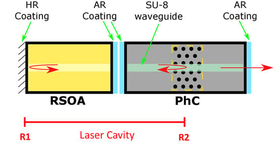
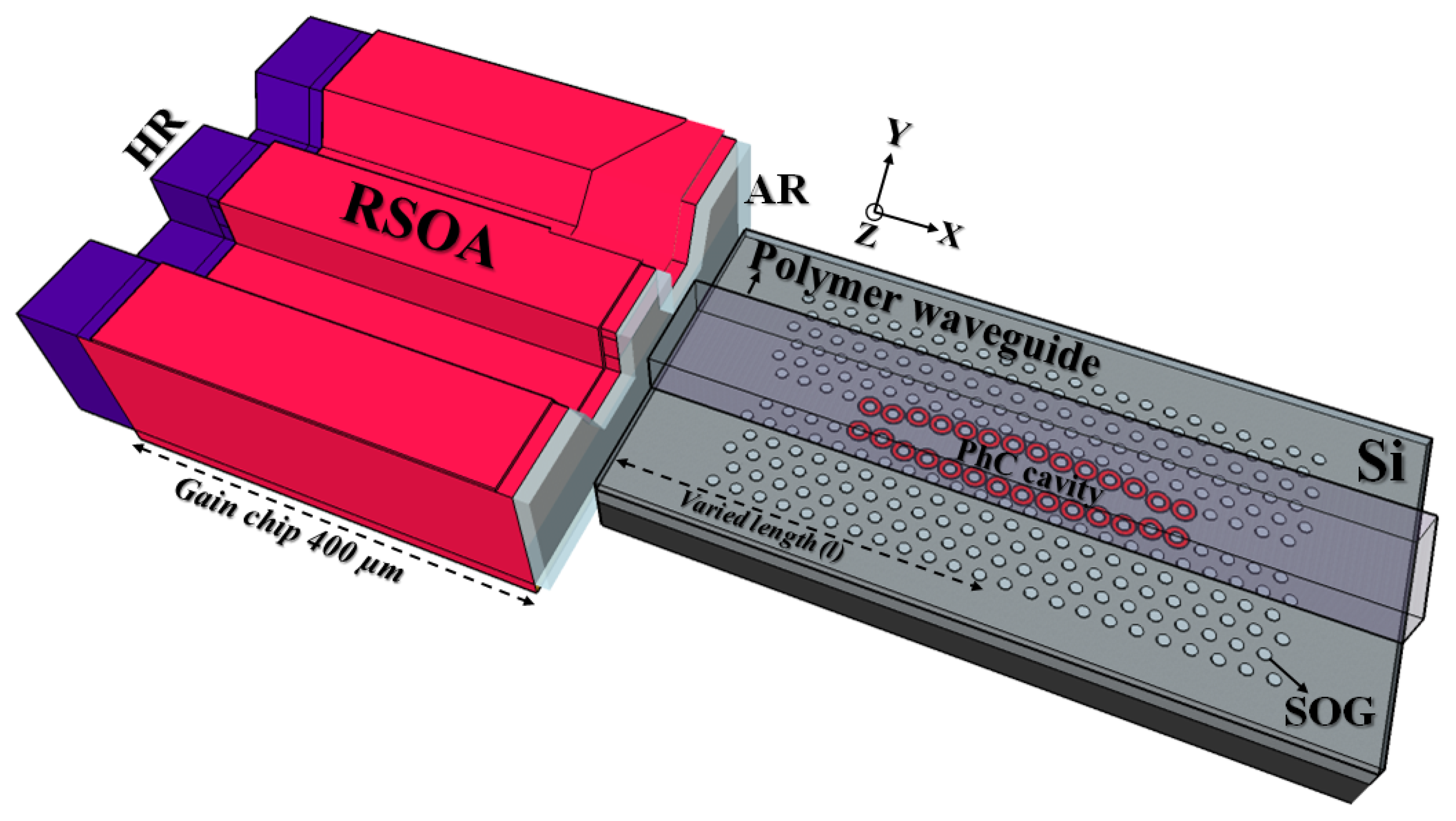
A 400 m long, ridge waveguide geometry based AlGaInAs/InP RSOA was utilised as the gain chip for the H-PhCL. The back facet of the RSOA waveguide is high-reflection (HR) coated, R > 90% to provide maximum reflection in the laser cavity and also to keep minimum power loss at this interface. The front facet of the RSOA waveguide is anti-reflection (AR) coated (R < 1%) to avoid parasitic reflections.
Figure 1 shows the schematic of the butt-coupled H-PhCL comprised of an RSOA chip for optical gain and a Si chip as the external reflector. The low refractive index polymer waveguide is utilised to couple light efficiently into the PhC cavity from the RSOA waveguide. The mode area of the RSOA waveguide is closely matched to that of the polymer waveguide resulting in high coupling efficiency. The polymer waveguide is vertically integrated with the Si chip and separated by a thin spin-on-glass (SOG) layer. The etched holes in the Si results in a strong refractive index contrast between the Si and SOG which creates the photonic bandgap, restricting the propagation of optical frequencies within the gap. Then the line defect created within the periodic lattice of the PhC allows a narrowband of optical frequencies to propagate within the bandgap. At the resonant frequency of the PhC cavity, the optical mode from the polymer waveguide evanescently couples to the PhC cavity mode [
13]. As a result, some of the light that is stored inside the PhC cavity couples back into the polymer waveguide mode in both forward and backward propagating directions. This gives a narrowband reflection peak at the resonance wavelength of the PhC cavity. Therefore, one or more longitudinal modes of the laser cavity are selected within PhC cavity reflection band [
14]. As the gain current increases, the optical length of the cavity changes, shifting the lasing mode with respect to the PhC resonance hence, creating the possibility that the lasing mode may hop to adjacent longitudinal modes. In our case, the LMS is controlled by selection of the appropriate polymer waveguide length from the chip input facet to PhC cavity
(l) to present a single longitudinal mode within the bandwidth of the reflector, thus minimising the tendency to mode-hop which will be further discussed in
Section 5.
3. Fabrication of Silicon PhC Cavity
The PhC cavity design used in this work is similar to the one used in [
15] with cavity dimensions of 20
m (L) × 10
m (W). Although this PhC cavity design has a relatively small FSR that results in multiple resonances within the range of interest, it is proven to be tolerant to fabrication imperfections and offers higher disorder stability and is suitable for mass manufacturing via Deep Ultra-Violet (DUV) photolithography [
16].
The fabrication process for the two dimensional Si PhC cavity begins with standard 220 nm silicon-on-insulator (on top of 2
m buried silicon dioxide commonly known as BOx) SOI wafer available from SOITEC. Electron-beam lithography followed by CHF
and SF
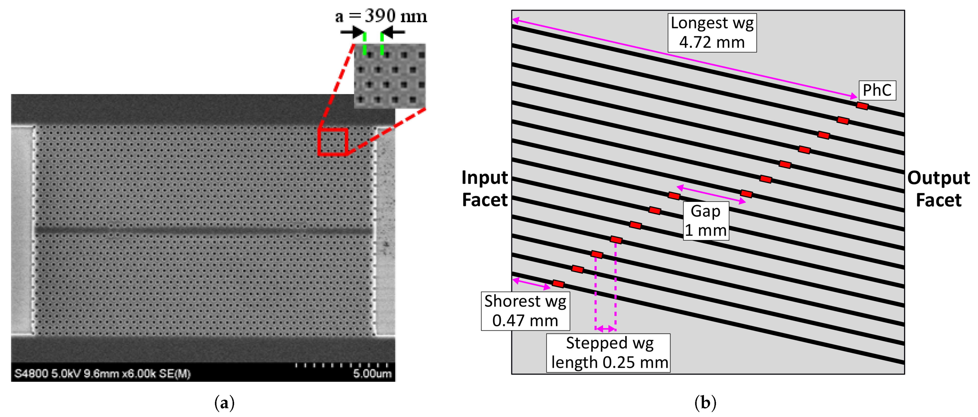
chemistry based dry etching process is used to define the PhC cavity structures on the 220 nm Si layer (
Figure 2a). In the following step, the fabricated PhC cavity is treated with solution, (i.e., H
SO
:H
O
in 3:1 ratio) to clean and improve the adhesion of the surface for the next step. The SOG polymer available from Honeywell (Accuglass-T) is used as an intermediate layer which fills the PhC cavity holes and the SOG refractive index of 1.46 is a close match to that of the SiO
. The intermediate layer improves the symmetry of the cavity mode and adds mechanical stability to the device. The thickness of this layer is critical to obtain the efficient coupling between the polymer waveguide mode and a PhC cavity mode [
13]. Once the target thickness is achieved, the device needs to be annealed at 425
C under N
atmosphere.
SU8 is used to form the polymer waveguide on top of the PhC structure. The targeted waveguide dimensions of 3 m (W) × 2 m (T) were chosen for TE single-mode operation at 1550 nm.
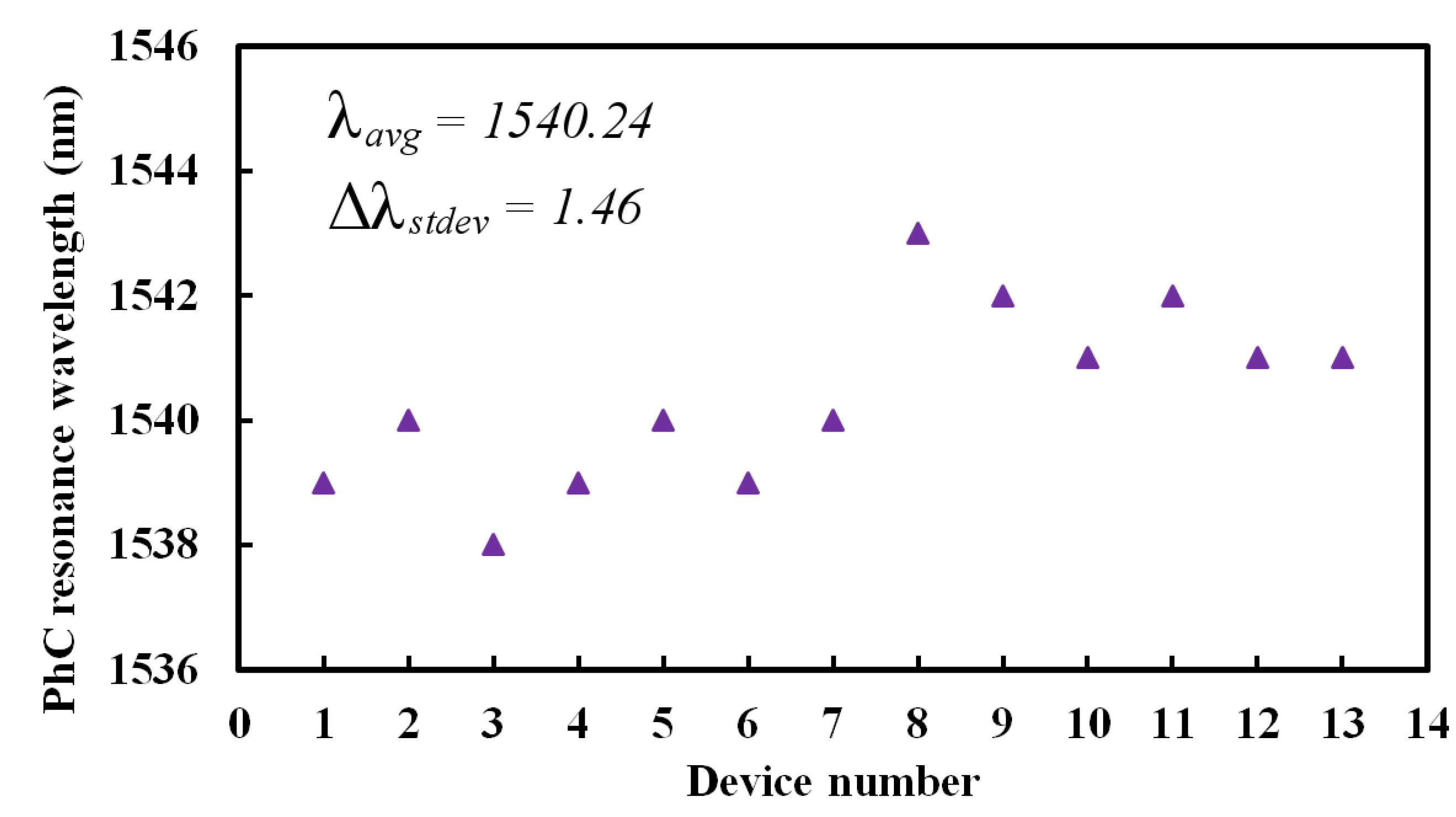
The intra-die variations of the fabricated PhC cavity were studied with the same lattice constant of a = 390 nm. The peak centre wavelength of the PhC cavity mode was obtained from the respective transmission spectra (see next section) of 13 devices. The average resonance wavelength was 1540.24 nm and the standard deviation was calculated as 1.46 nm (
Figure 3), thereby demonstrating high yield.
We interpret the small spread in resonance wavelength mainly due to imperfections related to device fabrication such as variations in PhC holes diameter across the sample.
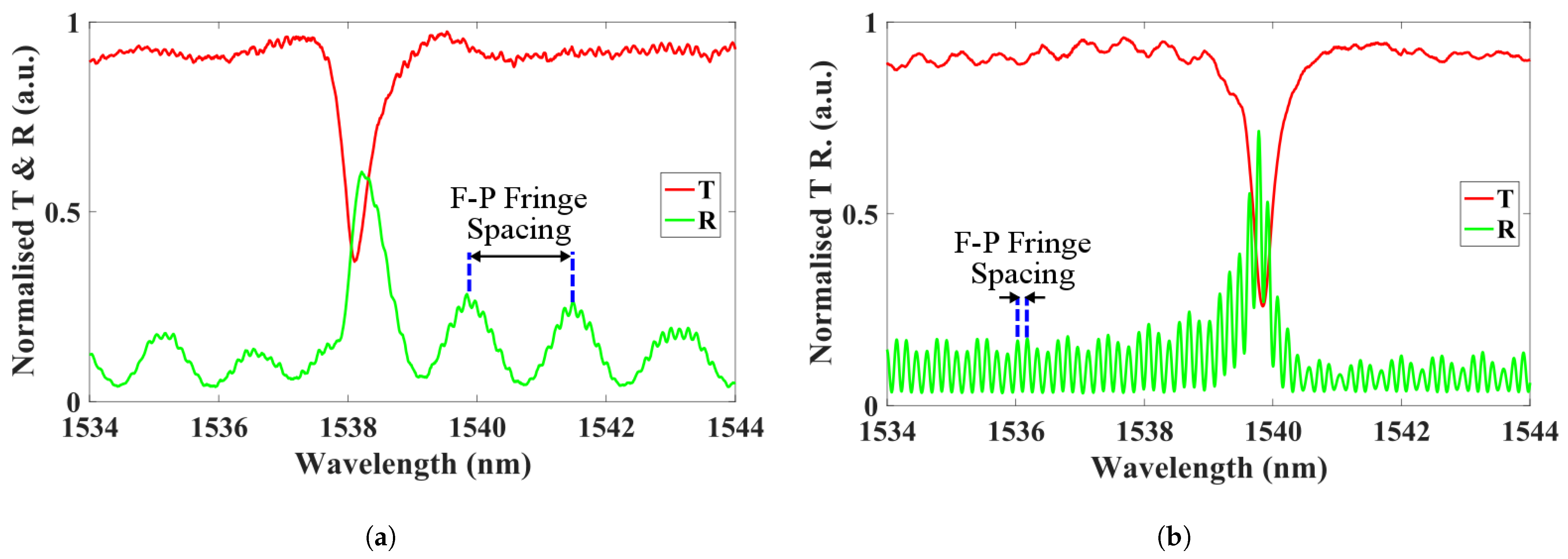
4. Fabry-Perot Fringe Spacing Measurements
To measure the passive characteristics of the PhC cavity (as a stand-alone device, i.e., without the RSOA), an “end-fire” experimental setup with a broadband amplified spontaneous emission (ASE) source and an optical spectrum analyser (OSA) was implemented and the transmission (T) spectrum was collected at the output facet of the waveguide. A fibre coupled broadband circulator was also used at the input facet of the waveguide to simultaneously measure the reflection (R) spectrum. The OSA was kept at the highest possible resolution of 50 pm and all measurements were performed at room temperature of 20 C.
We fabricated nominally identical PhC cavities located at different positions on the Si chip as shown in
Figure 2b which allowed us to vary the polymer waveguide length as indicated in
Figure 1 marked as
varied length (l)—the length from the chip input facet to the PhC cavity. The length of the polymer waveguide was varied from 0.47 mm to 4.72 mm and the T and R spectra of each of the devices were measured for the different waveguide lengths.
Figure 4 shows the results obtained for the devices with the shortest (0.47 mm) and longest (4.72 mm) waveguide lengths—the solid red and green line indicates the T and R spectrum, respectively. The varied waveguide length changes the fringe spacing of the Fabry–Perot cavity modes in the reflection spectrum, according to:
where
c is the speed of light,
is the group index and
L is the length of the SU8 waveguide—
varied length (l). The measured fringe spacing was 204 GHz and 18.5 GHz for an SU8 waveguide length of 0.47 mm and 4.72 mm, respectively.
This Dispersion Adapted (DA) cavity design can support multiple resonance modes with varying bandwidth and reflectivity typically separated by ∼6 nm—the FSR of the PhC cavity resonator. The PhC resonance mode at ∼1540 nm had a full-width half maximum (FWHM) of 48 GHz, obtained by fitting a Lorentzian function. Using the equations derived in [
13], we calculated the total quality factor and the reflectivity of the PhC mode as 3855 and 49%, respectively. The RSOA gain spectrum also had a peak centered at ∼1540 nm and given the sufficient reflectivity from the PhC mode, lasing occurred at that wavelength.
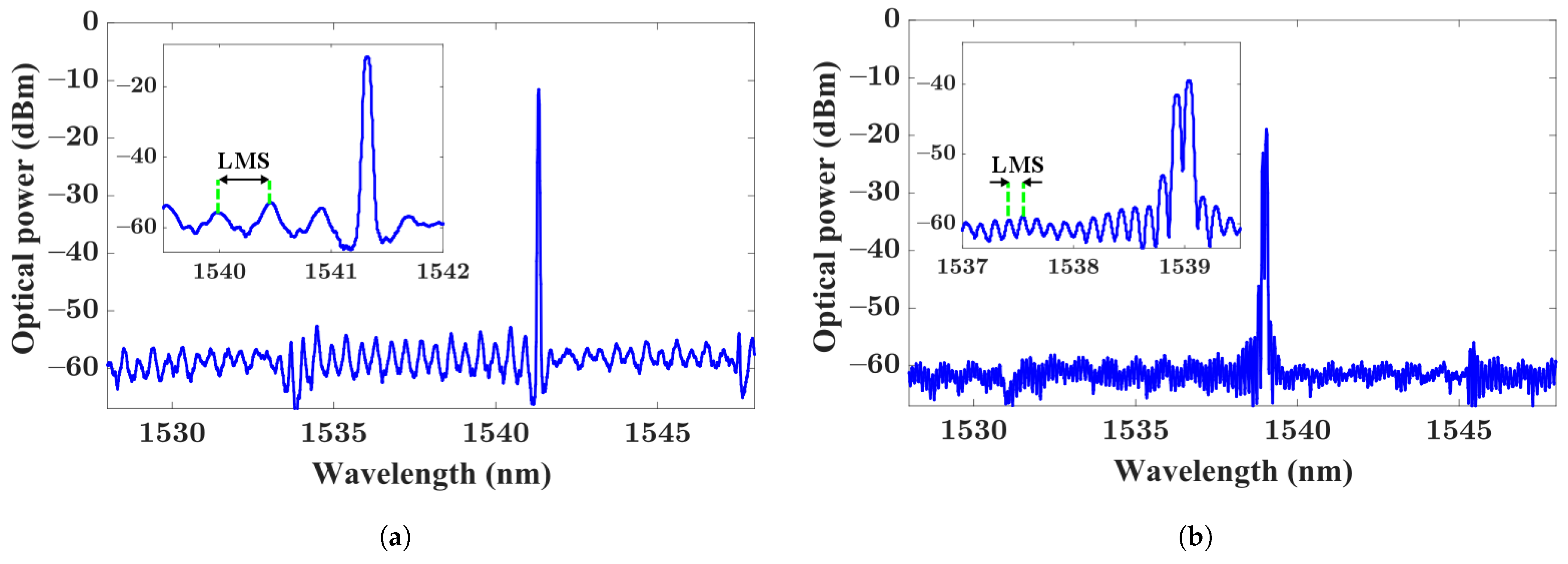
For the laser measurements, the RSOA chip was butt-coupled to the Si chip as described in
Section 2. Both chips were mounted on top of a Peltier to keep the temperature constant at 20
C. The same RSOA device was used throughout all the laser measurements (thereby, keeping the gain section length fixed). The output of the laser was collected using a lensed fibre at the waveguide output facet of the Si chip and measured using an OSA. The total length of the laser cavity included the 400
m long RSOA in addition to the polymer waveguide length. Hence by expanding Equation (
1), the LMS of the laser cavity including the RSOA is given by:
where
is the group index and
L is the length of the RSOA waveguide. Therefore, as the RSOA length remained fixed, we controlled the LMS by changing only one parameter:
—by means of varying the length of the polymer waveguide.
For a fixed bias current on the RSOA of 50 mA,
Figure 5a,b show the lasing spectrum of the H-PhCL with laser cavity lengths of 0.87 mm and 5.12 mm, respectively. These correspond to the same devices without the RSOA shown in
Figure 4a,b. We assumed the LMS from the wavelength difference between the Fabry–Perot fringes on the lasing spectrum as these closely corresponded to the calculated values of the total optical length of the laser cavity. The measured LMS was 67 GHz and 16 GHz for a cavity length of 0.87 mm and 5.12 mm, respectively.
Analysis of the FWHM data obtained from the measured PhC transmission spectrum shows that the H-PhCL can operate in two different regimes, dependent on the ratio of the LMS and FWHM of the reflector:
- (i.)
LMS < FWHM
When the LMS is smaller than the FWHM of the resonant reflector, one or more longitudinal modes of the laser cavity can exist within the bandwidth of the PhC reflector. This is evident in
Figure 5b where multi-mode lasing occurs due to the availability of multiple longitudinal modes within the reflector bandwidth.
- (ii.)
LMS > FWHM
When the LMS is larger than the FWHM of the resonant reflector, one longitudinal mode lies within the reflector bandwidth and results in an SMSR of >40 dB (
Figure 5a). This also eliminates the possibility of mode-hopping which will be further discussed in the next section.
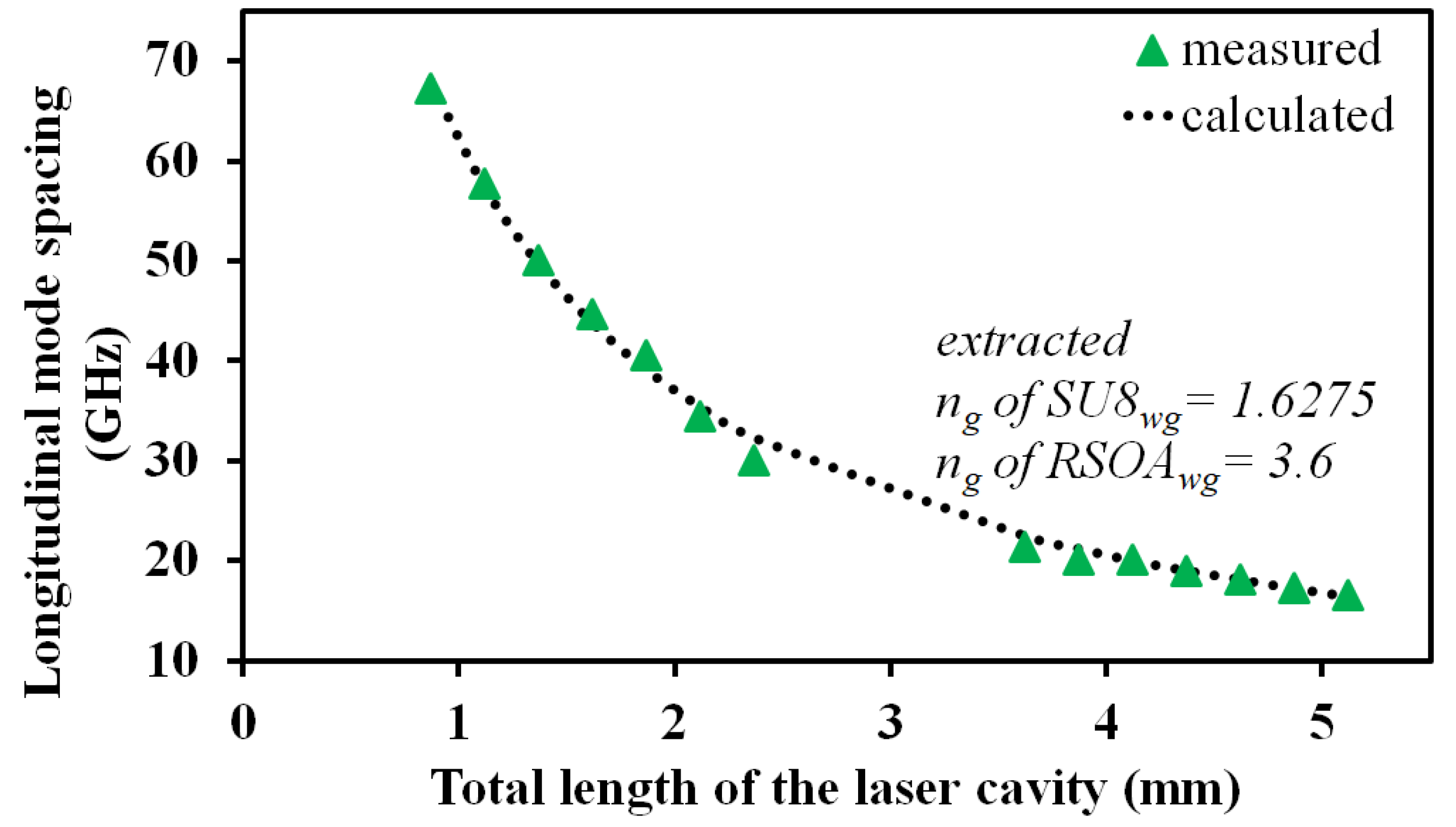
The varied polymer waveguide length allowed calculation of the group index,
, which in turn helped to give an accurate determination of the group index of the RSOA,
, as a function of the LMS of the laser cavity using Equation (
2). The results are shown in
Figure 6 and the green triangle indicates the measured LMS at a fixed gain current of 50 mA that varies between 67 to 16 GHz as a function of the total length laser cavity.
The calculation of the group index values for the waveguides is the facilitation for exact cavity length design and fabrication to ensure the extended mode-hop free operating regime.
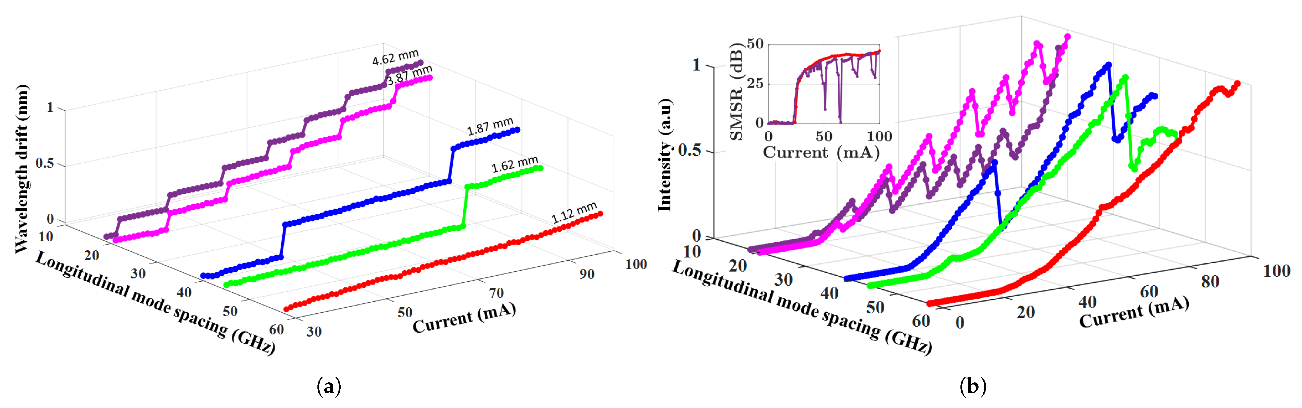
5. Mode-Hopping Characteristics of the H-PhCL with Varied Gain Current
In this section, we study the mode-hopping characteristics of the H-PhCL for various LMS with respect to the fixed reflector bandwidth. The gain current of the RSOA was stepped from 0 mA to 100 mA in steps of 1 mA and the peak lasing wavelength was obtained from the OSA for each step.
Figure 7 shows the results for five devices with LMS of 18, 20, 39, 44 and 57 GHz for laser cavity lengths of 4.62, 3.87, 1.87, 1.62 and 1.12 mm, respectively. As each device lased on the same PhC resonance mode, the reflector bandwidth was fixed at 48 GHz. Four of these devices showed continuous mode-hopping in laser wavelength as the gain current was stepped. This was due to the availability of multiple longitudinal modes within the reflector bandwidth and the laser exhibited mode-hopping to the adjacent longitudinal mode as these met condition (
i.) LMS < FWHM. One device showed lasing operation with a stable single-mode over the gain current range studied. As the FWHM of the reflector was 48 GHz, the LMS was clearly above this at 57 GHz thereby, satisfying condition (
ii.) LMS > FWHM. As a result, stable single-mode operation was attained up to 100 mA, i.e., four times the laser threshold current.
The increased drift in laser wavelength with decreasing LMS can be attributed to the larger number of mode-hops within the same current range. The device with the largest LMS showed the least drift on account of continuous single-mode operation over the current range. Notably, the red-shift in lasing wavelength with increased bias current was as a consequence of both variation in optical cavity length by changes in the RSOA material refractive index with temperature and increased heat dissipation in the PhC cavity causing the reflection peak to tune synchronously with the lasing mode as described in [
11], which also contributes to continuous single-mode operation of the device.
The light-current (L-I) curves of the respective devices are shown in
Figure 7b with the output power normalised to compare the devices of different LMS. On average, the maximum output power attained was 1 mW. The jumps in output power were caused by the mode-hopping mechanism for devices which satisfied condition (
i.). The steady increase in power with increasing current was evident for the device with largest LMS thus satisfying condition (
ii.) again, indicating continuous single-mode operation over the bias current range.
The effect on the SMSR over the current range depending on the LMS was also observed. As shown in
Figure 7b: inset, the shorter laser cavity (largest LMS), which does not exhibit mode-hopping had stable SMSR throughout the current range. Conversely for the longer laser cavity, the SMSR was greatly reduced as there was the transition to multi-mode lasing and subsequently mode-hopping at those currents.


 ,
, 


