Effects of Selective Laser Modification and Al Deposition on the Hot Corrosion Resistance of Ceria and Yttria-Stabilized Zirconia Thermal Barrier Coatings

Abstract
:1. Introduction
2. Materials and Methods
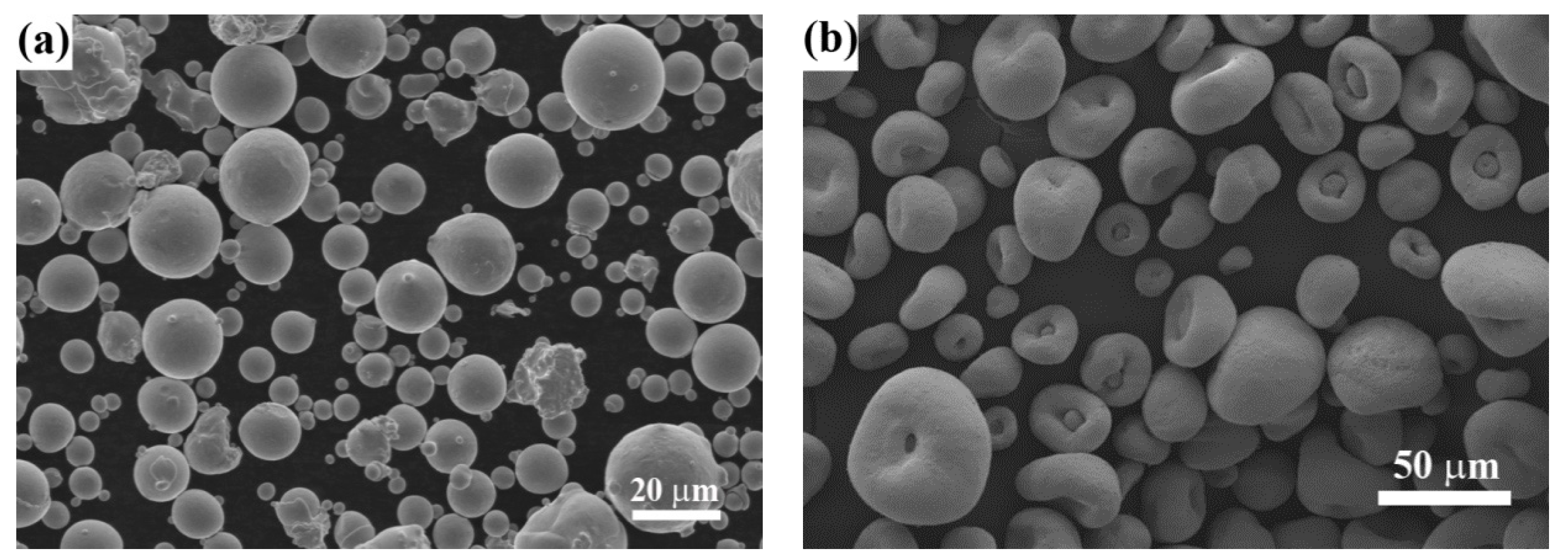
2.1. Materials
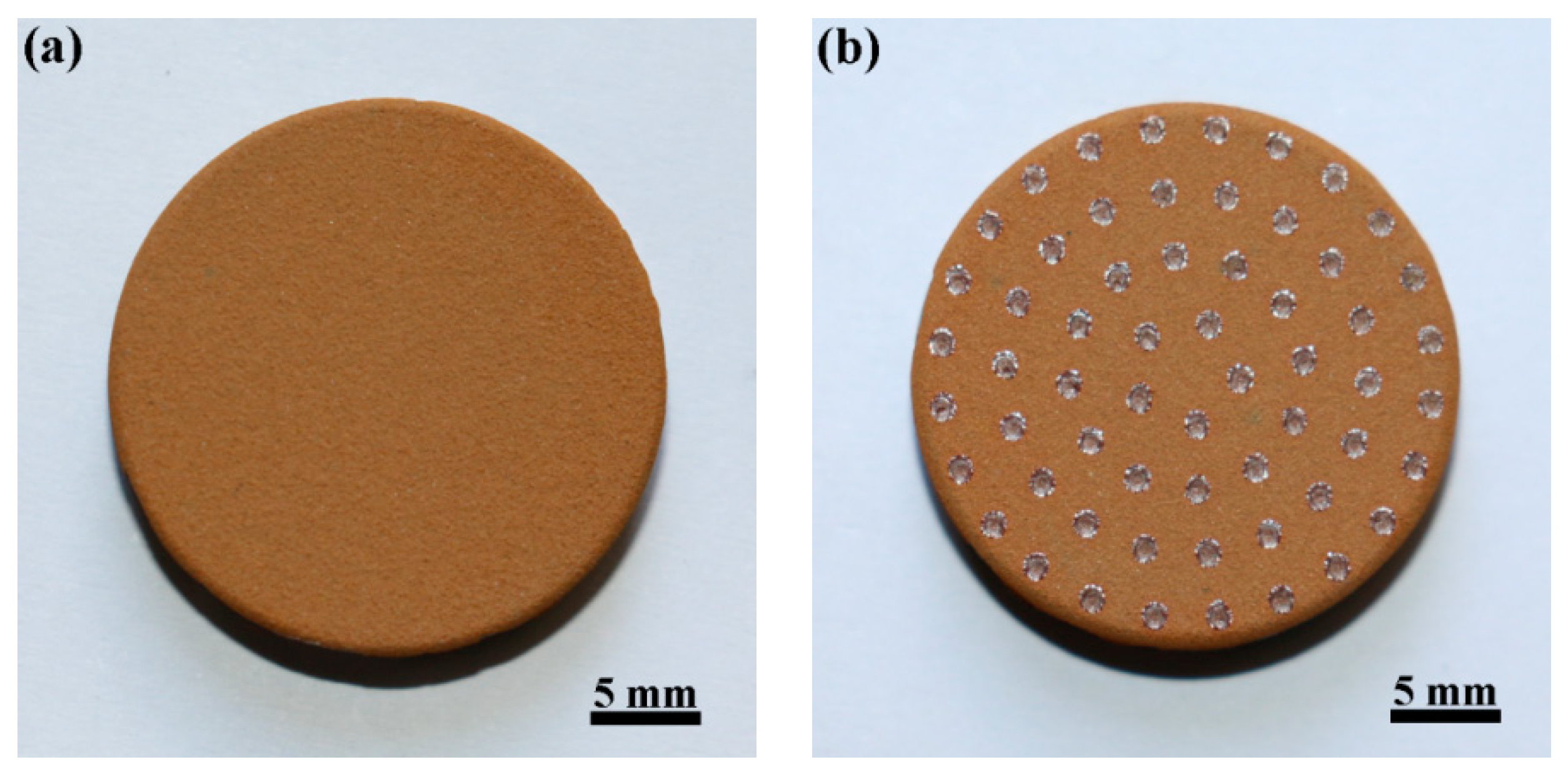
2.2. Laser Remelting Process
2.3. Al Deposition
2.4. Hot Corrosion Tests
2.5. Characterization
3. Results and Discussion
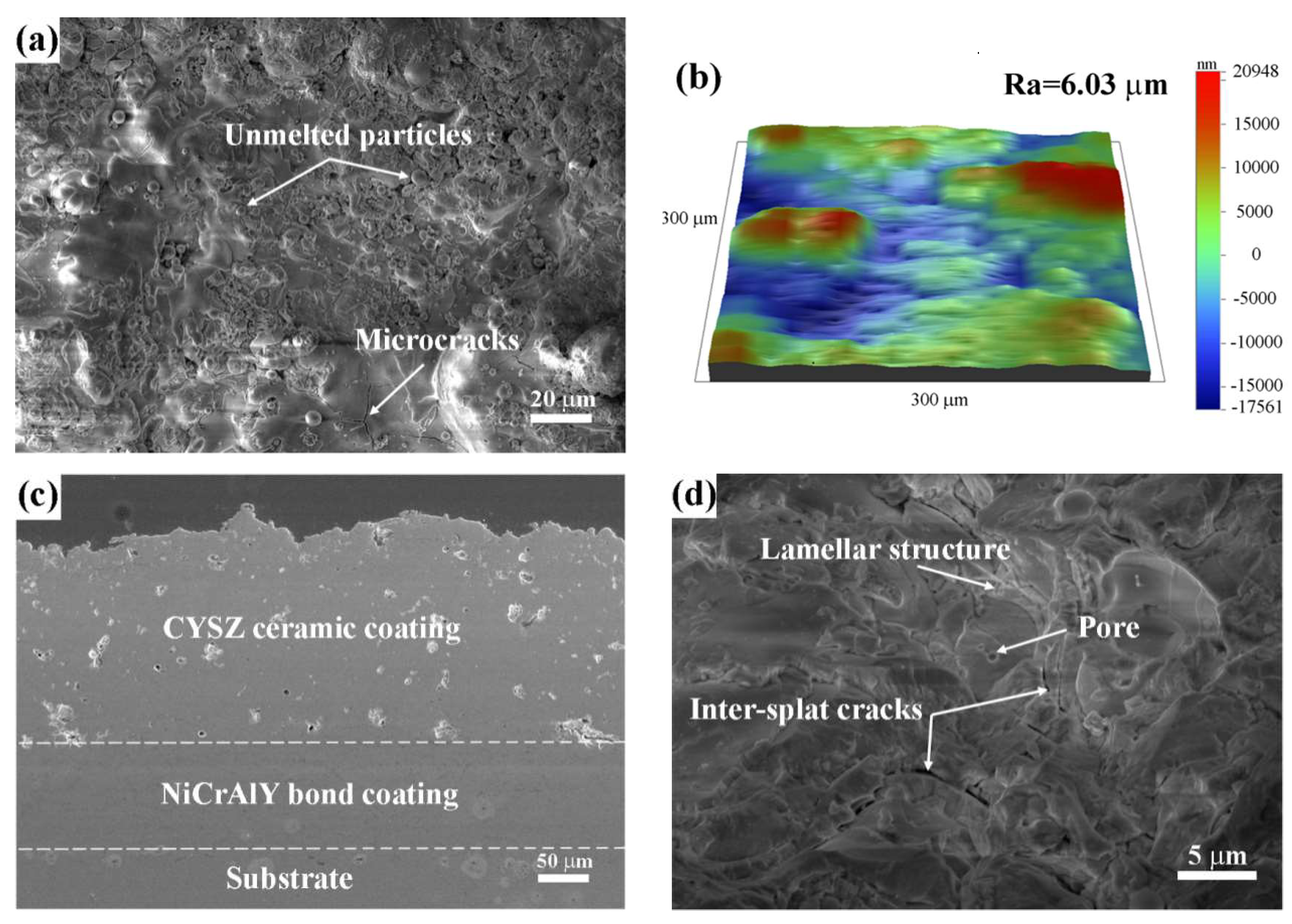
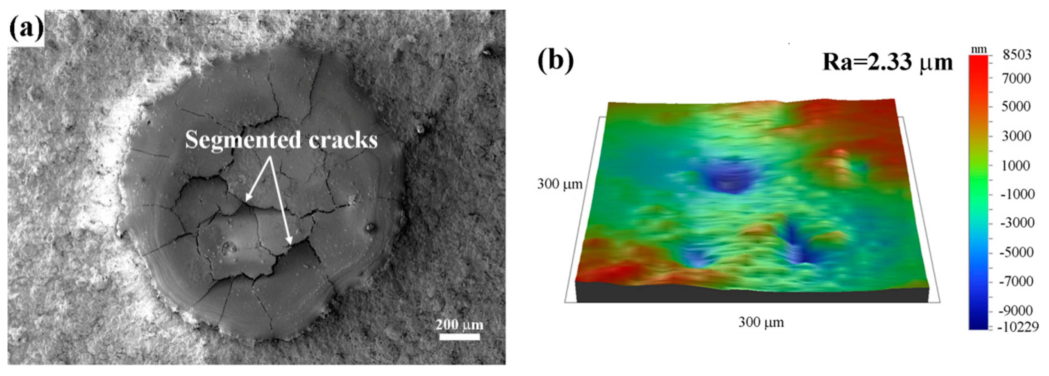
3.1. Microstructure
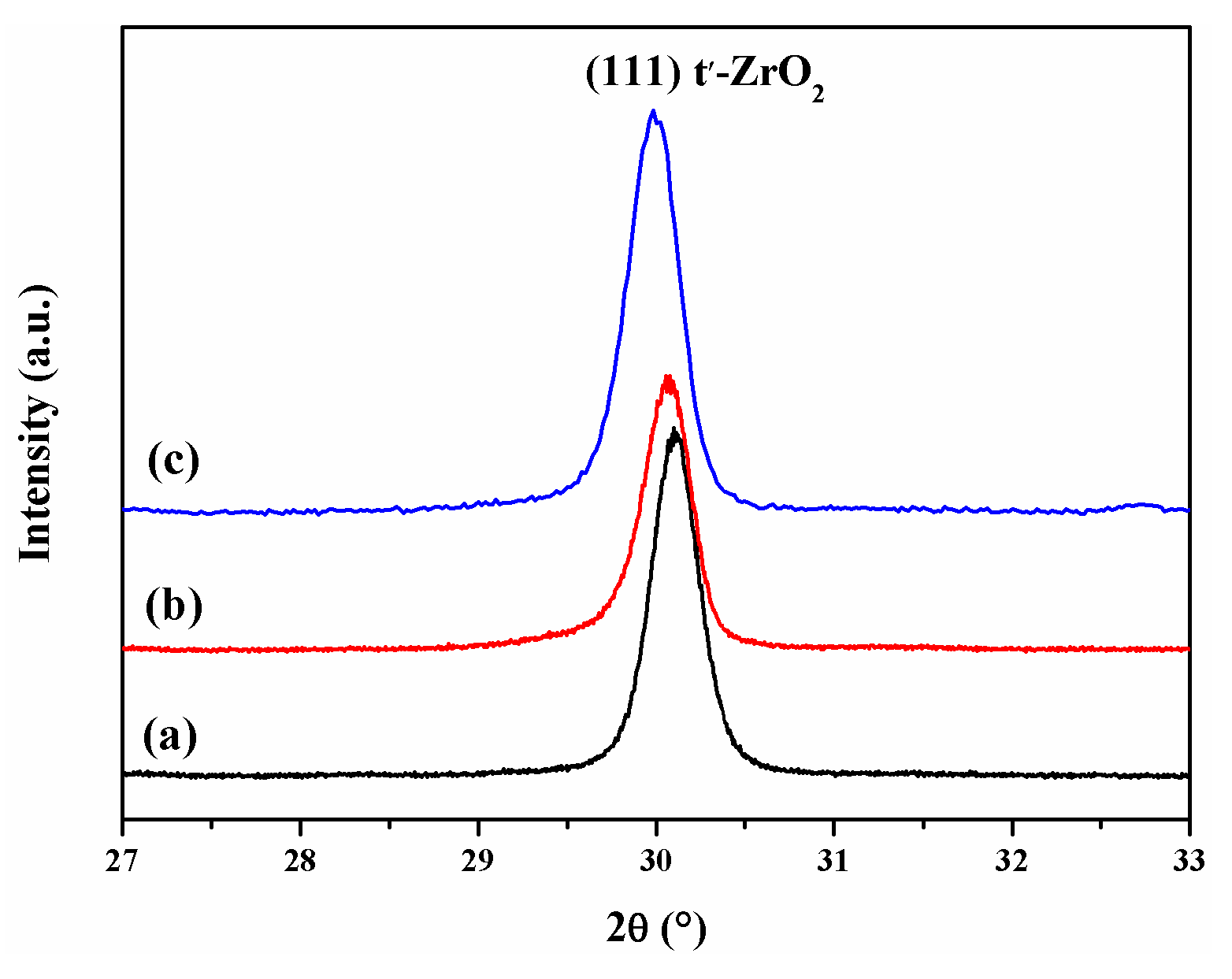
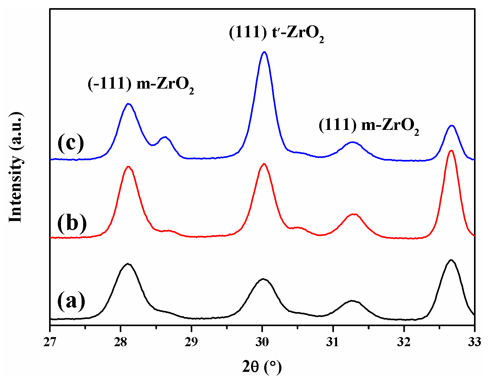
3.2. Phase Composition
3.3. Characterization of Coatings after Hot Corrosion
3.3.1. Microstructure Observation and Phase Analysis
3.3.2. Hot Corrosion Reactions
3.3.3. Comparison of Hot Corrosion Resistance of Different Coatings
4. Conclusions
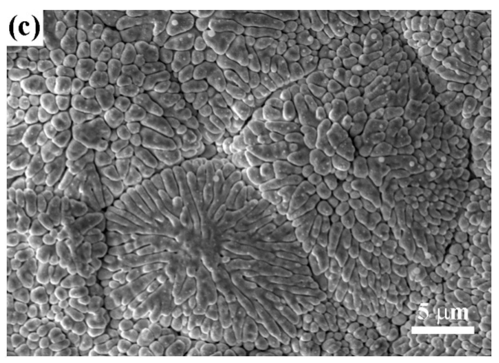
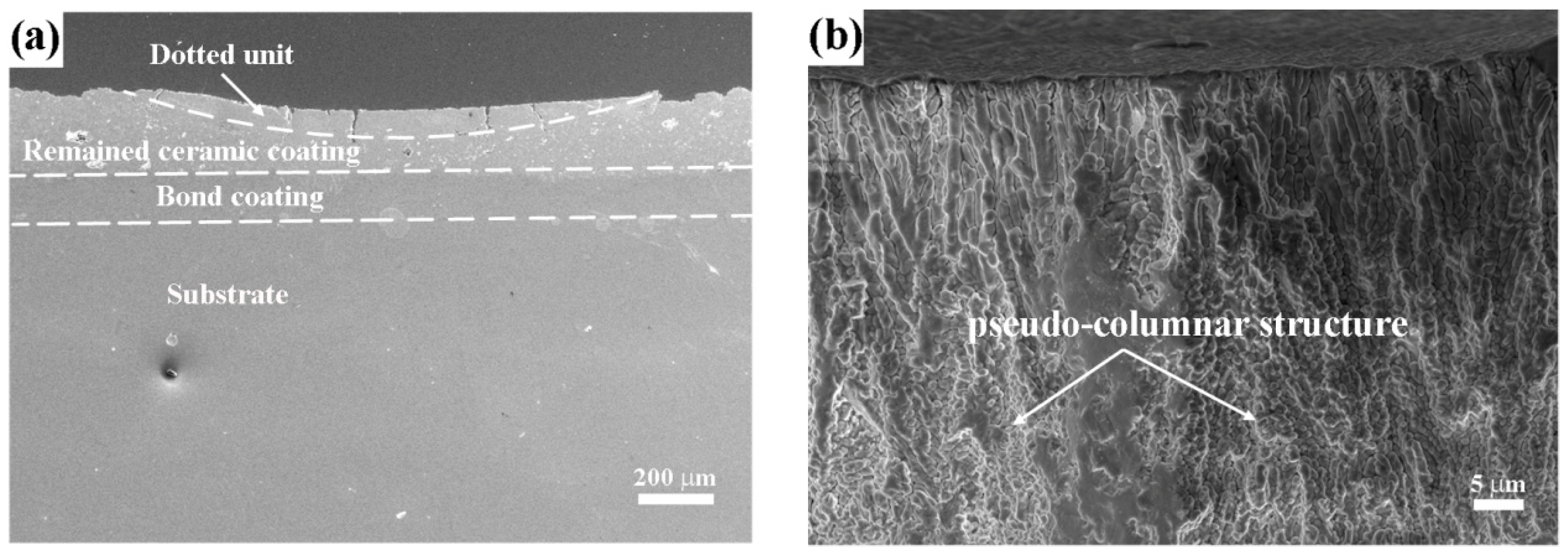
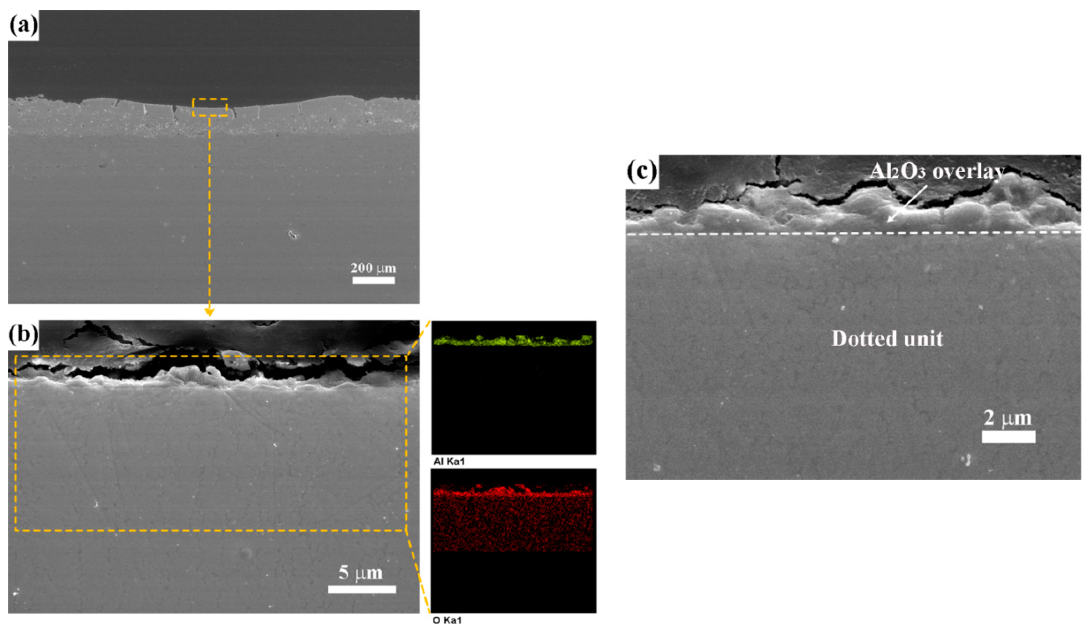
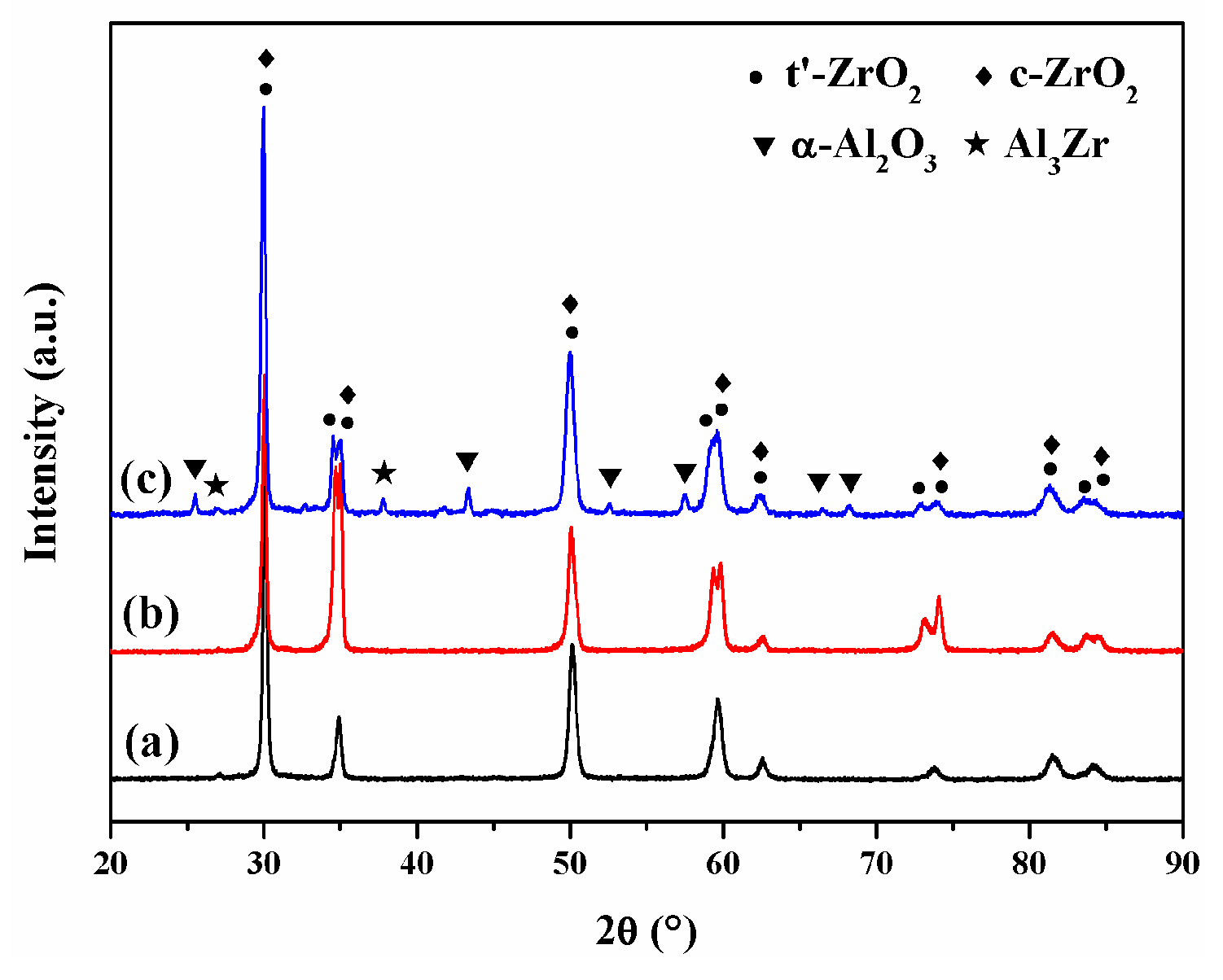
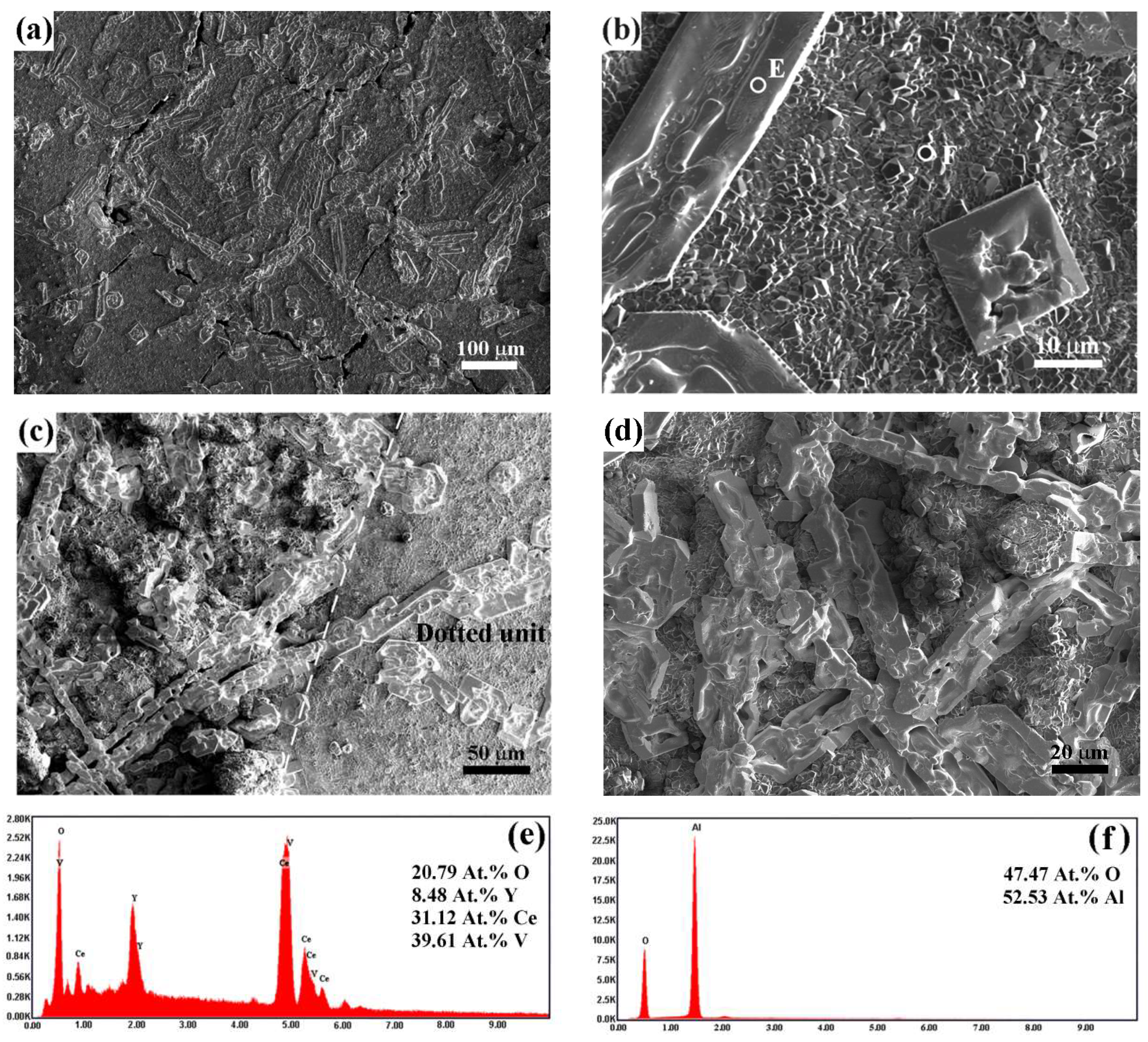
- The dotted coating with some discrete and dense dotted units was produced by selective laser remelting. The dotted units showed a dense pseudo-columnar crystal structure and vertical cracks. The direct current circular magnetron sputtering was used to deposit Al film on the dotted coating, and vacuum heat treatment was subsequently performed to produce a dense α-Al2O3 overlay through the in-situ reaction of Al and ZrO2.
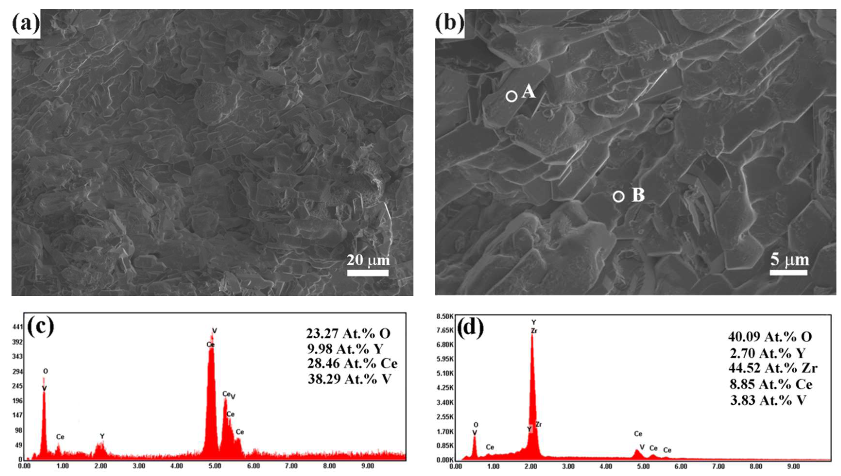
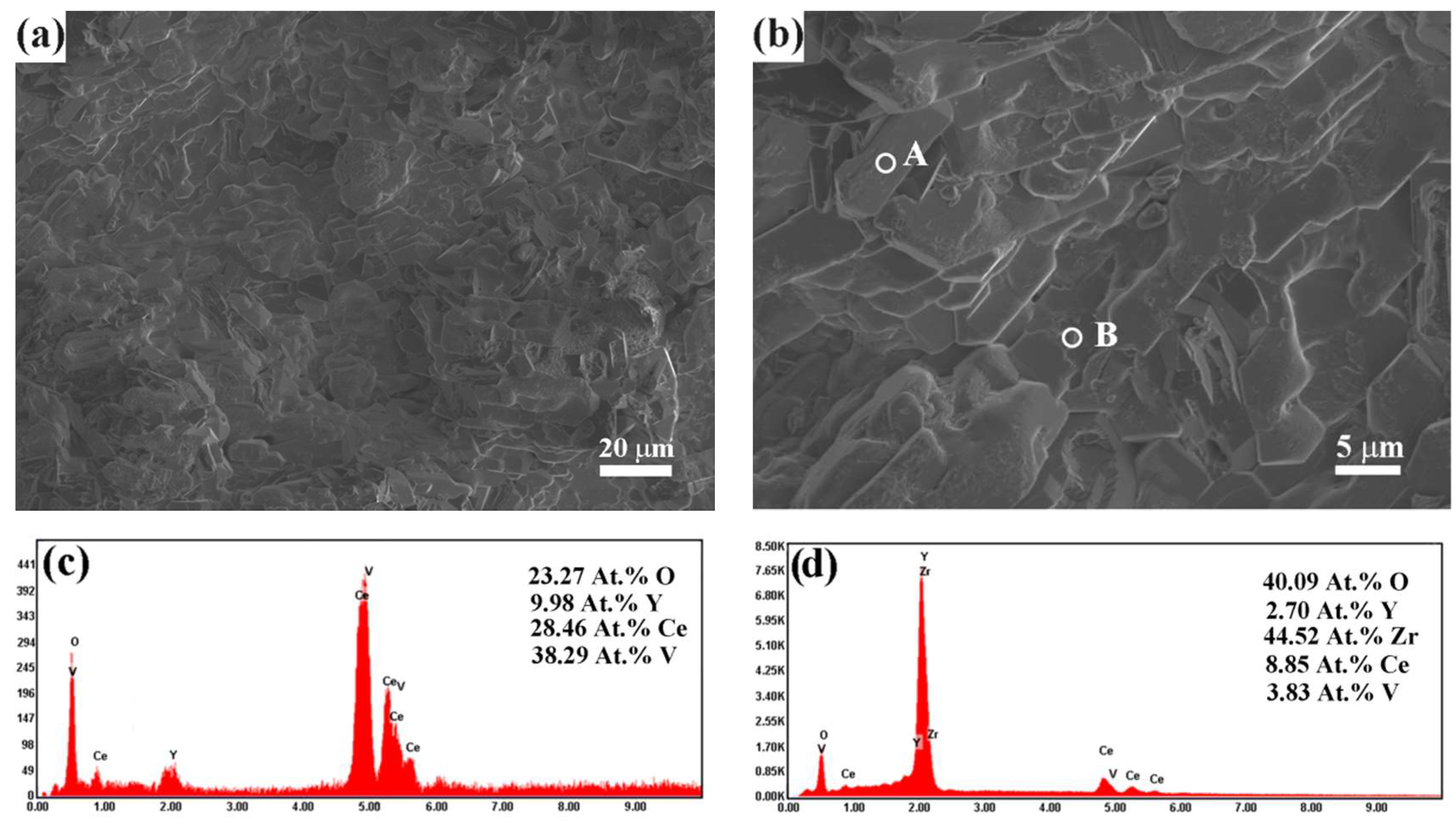
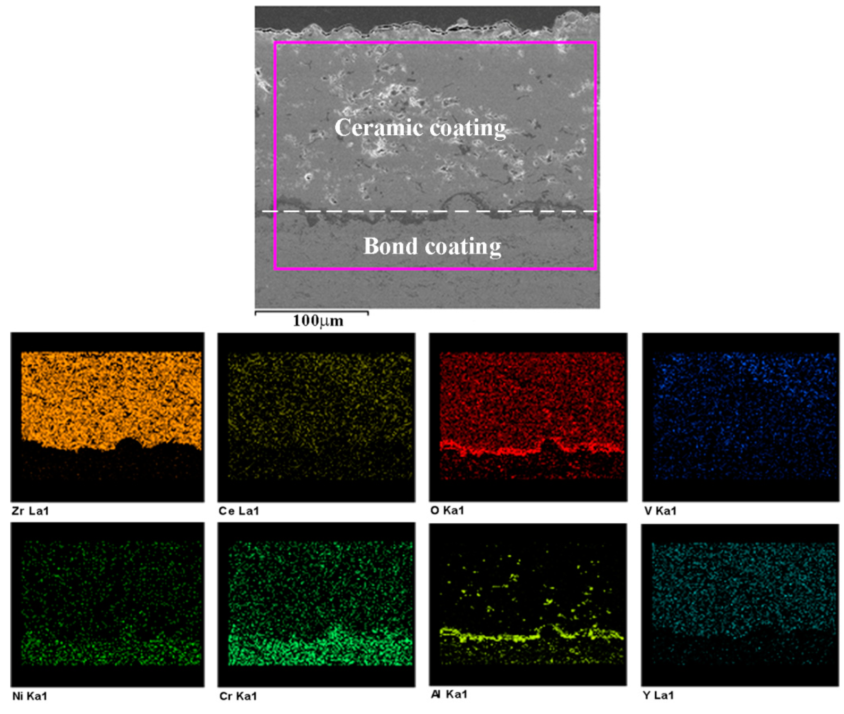
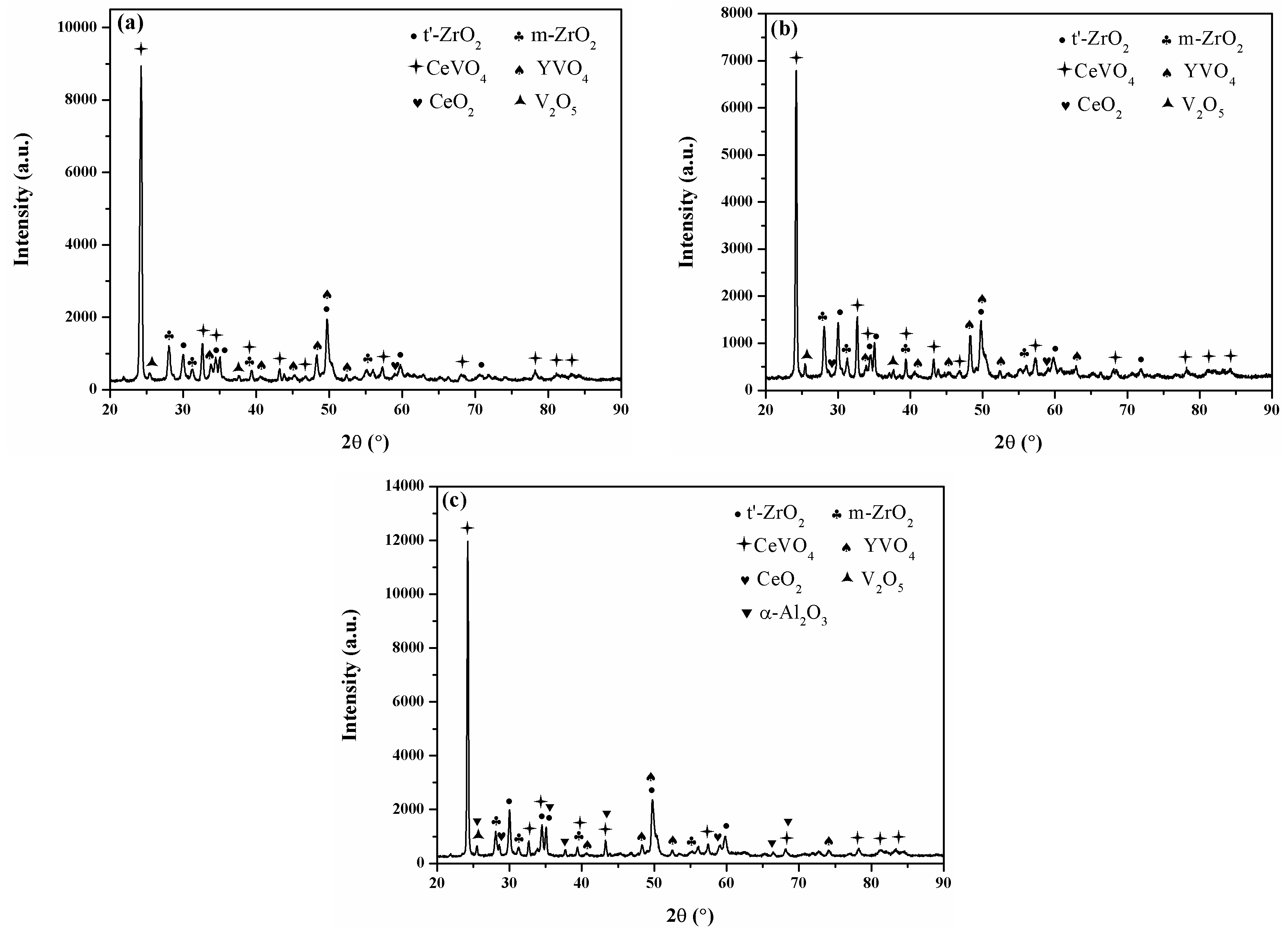
- The reaction between the molten salts and zirconia stabilizers (Y2O3 and CeO2) led to the generation of YVO4 and CeVO4 plate-shaped crystals, and the mineralization of CeO2. The depletion of stabilizers caused the detrimental phase transformation of t-ZrO2 to m-ZrO2. Finally, the stresses resulting from phase transformation and the generation of hot corrosion products, and the bondcoat oxidation caused the failure of CYSZ coatings.
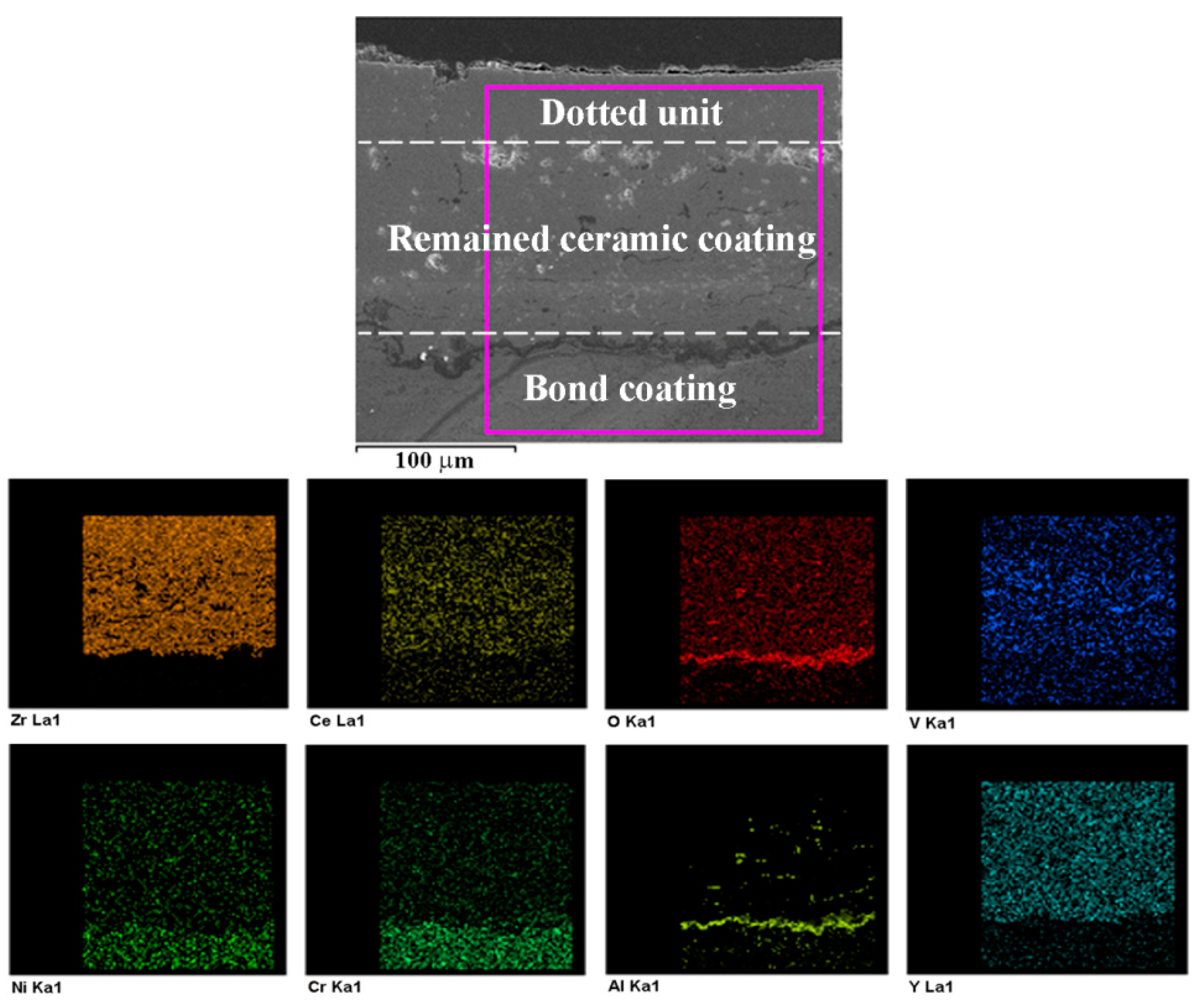
- The dotted coating had superior heat corrosion resistance in comparison with the plasma-sprayed coating. The minimal surface roughness and the dense dotted units significantly contributed to improving the hot corrosion resistance of the dotted coating. However, the dotted units with vertical cracks did not completely avoid the contact between the molten salts and the CYSZ coating, which further limited the improvement in hot corrosion resistance of the dotted coating.
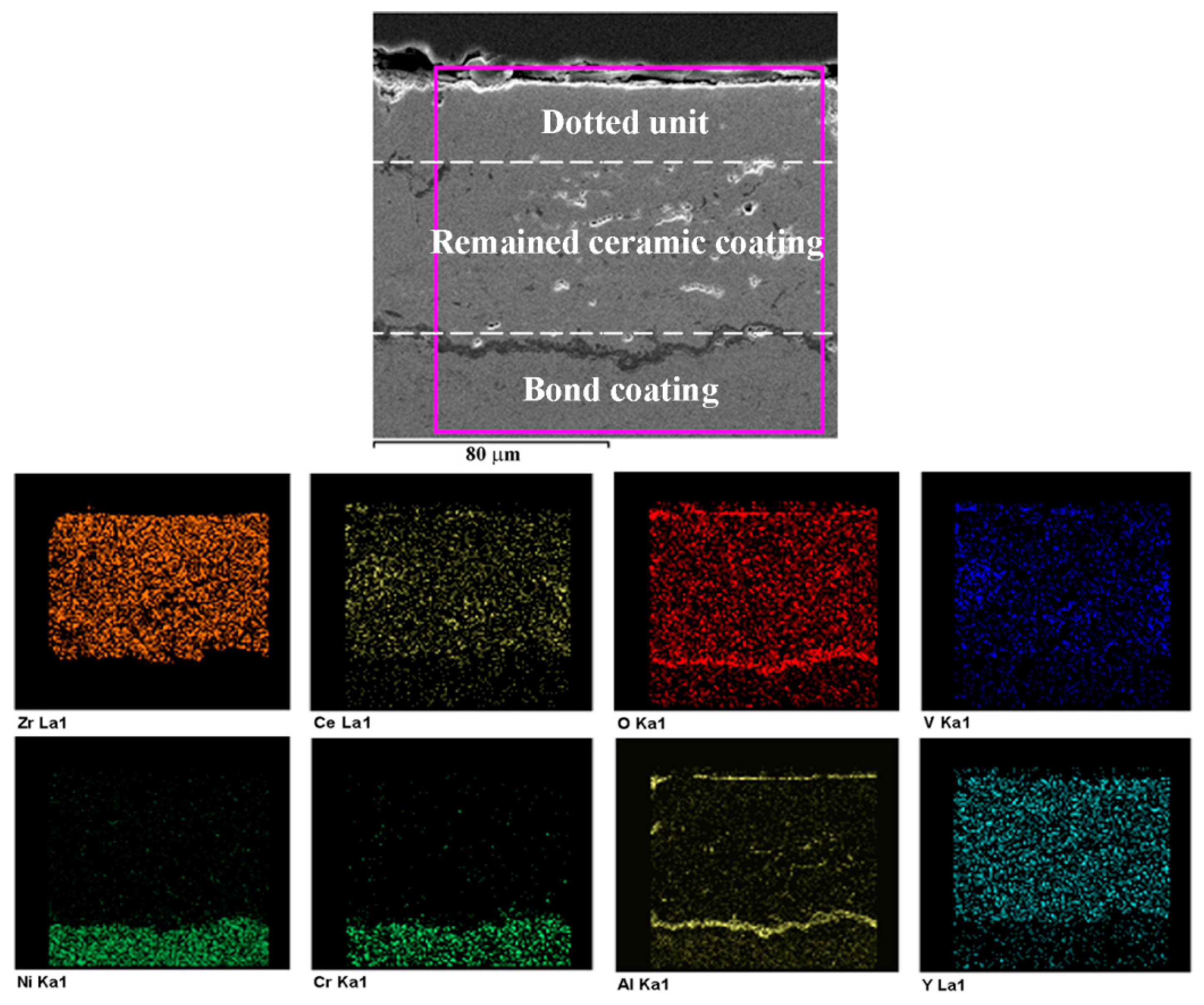
- The dense α-Al2O3 overlay with chemical inertness effectively inhibited the infiltration of molten salts into the CYSZ coating and separated the corrosive salts from the CYSZ coating, which considerably reduced the hot corrosion reaction between the CYSZ ceramic coating and the molten salts. The selective laser remelting combined with Al deposition can maximize the hot corrosion resistance of TBCs. Therefore, the DA coating showed the best hot corrosion resistance.
Author Contributions
Funding
Conflicts of Interest
References
- Ramachandran, C.S.; Balasubramanian, V.; Ananthapadmanabhan, P.V.; Viswabaskaran, V. Influence of the intermixed interfacial layers on the thermal cycling behaviour of atmospheric plasma sprayed lanthanum zirconate based coatings. Ceram. Int. 2012, 38, 4081–4096. [Google Scholar] [CrossRef]
- Roy, C.K.; Noor-A-Alam, M.; Choudhuri, A.R.; Ramana, C.V. Synthesis and microstructure of Gd2O3-doped HfO2 ceramics. Ceram. Int. 2012, 38, 1801–1806. [Google Scholar] [CrossRef]
- Meng, G.; Zhang, B.; Liu, H.; Yang, G.; Xu, T.; Li, C.; Li, C. Highly oxidation resistant and cost effective MCrAlY bond coats prepared by controlled atmosphere heat treatment. Surf. Coat. Technol. 2018, 347, 54–65. [Google Scholar] [CrossRef]
- Zhang, T.; Huang, C.; Lan, H.; Du, L.; Zhang, W. Oxidation and hot corrosion behavior of plasma-sprayed MCrAlY–Cr2O3 coatings. J. Therm. Spray Technol. 2016, 25, 1208–1216. [Google Scholar] [CrossRef]
- Terberger, P.J.; Sebold, D.; Webler, R.; Ziener, M.; Neumeier, S.; Klein, L.; Virtanen, S.; Goken, M.; Vassen, R. Isothermal aging of a gamma’-strengthened Co–Al–W alloy coated with vacuum plasma-sprayed MCrAlY bond coats. Surf. Coat. Technol. 2015, 276, 360–367. [Google Scholar] [CrossRef]
- Zhang, B.; Shi, J.; Yang, G.; Li, C.; Li, C. Healing of the interface between splashed particles and underlying bulk coating and its influence on isothermal oxidation behavior of LPPS MCrAlY bond coat. J. Therm. Spray Technol. 2015, 24, 611–621. [Google Scholar] [CrossRef]
- Tillmann, W.; Schaak, C.; Hagen, L.; Mauer, G.; Matthaus, G. Internal diameter coating processes for bond coat (HVOF) and thermal barrier coating (APS) systems. J. Therm. Spray Technol. 2019, 28, 233–241. [Google Scholar] [CrossRef]
- Hashemi, S.M.; Parvin, N.; Valefi, Z. Effect of microstructure and mechanical properties on wear behavior of plasma-sprayed Cr2O3–YSZ–SiC coatings. Ceram. Int. 2019, 45, 5284–5296. [Google Scholar] [CrossRef]
- Wu, Y.; Luo, H.; Cai, C.; Wang, Y.; Zhou, Y.; Yang, L.; Zhou, G. Comparison of CMAS corrosion and sintering induced microstructural characteristics of APS thermal barrier coatings. J. Mater. Sci. Technol. 2019, 35, 440–447. [Google Scholar] [CrossRef]
- Georgiopoulos, I.; Vourdas, N.; Mirza, S.; Andreouli, C.; Stathopoulos, V. LaAlO3 as overlayer in conventional thermal barrier coatings. Proced. Struct. Integr. 2018, 10, 280–287. [Google Scholar] [CrossRef]
- Shen, Z.; He, L.; Xu, Z.; Mu, R.; Huang, G. LZC/YSZ DCL TBCs by EB-PVD: Microstructure, low thermal conductivity and high thermal cycling life. J. Eur. Ceram. Soc. 2019, 39, 1443–1450. [Google Scholar] [CrossRef]
- Steinberg, L.; Naraparaju, R.; Heckert, M.; Mikulla, C.; Schulz, U.; Leyens, C. Erosion behavior of EB-PVD 7YSZ coatings under corrosion/erosion regime: Effect of TBC microstructure and the CMAS chemistry. J. Eur. Ceram. Soc. 2018, 38, 5101–5112. [Google Scholar] [CrossRef]
- Chen, X.; Zhao, Y.; Fan, X.; Liu, Y.; Zou, B.; Wang, Y.; Ma, H.; Cao, X. Thermal cycling failure of new LaMgAl11O19/YSZ double ceramic top coat thermal barrier coating systems. Surf. Coat. Technol. 2011, 205, 3293–3300. [Google Scholar] [CrossRef]
- Bai, Y.; Han, Z.; Li, H.; Xu, C.; Xu, Y.; Wang, Z.; Ding, C.; Yang, J. High performance nanostructured ZrO2 based thermal barrier coatings deposited by high efficiency supersonic plasma spraying. Appl. Surf. Sci. 2011, 257, 7210–7216. [Google Scholar] [CrossRef]
- Ahmadi-Pidani, R.; Shoja-Razavi, R.; Mozafarinia, R.; Jamali, H. Laser surface modification of plasma sprayed CYSZ thermal barrier coatings. Ceram. Int. 2013, 39, 2473–2480. [Google Scholar] [CrossRef]
- Doleker, K.M.; Ozgurluk, Y.; Karaoglanli, A.C. Isothermal oxidation and thermal cyclic behaviors of YSZ and double-layered YSZ/La2Zr2O7 thermal barrier coatings (TBCs). Surf. Coat. Technol. 2018, 351, 78–88. [Google Scholar] [CrossRef]
- Thibblin, A.; Jonsson, S.; Olofsson, U. Influence of microstructure on thermal cycling lifetime and thermal insulation properties of yttria-stabilized zirconia thermal barrier coatings for diesel engine applications. Surf. Coat. Technol. 2018, 350, 1–11. [Google Scholar] [CrossRef]
- Tsipas, S.A.; Golosnoy, I.O. Effect of substrate temperature on the microstructure and properties of thick plasma-sprayed YSZ TBCs. J. Eur. Ceram. Soc. 2011, 31, 2923–2929. [Google Scholar] [CrossRef] [Green Version]
- Shao, F.; Zhao, H.; Zhong, X.; Zhuang, Y.; Cheng, Z.; Wang, L.; Tao, S. Characteristics of thick columnar YSZ coatings fabricated by plasma spray-physical vapor deposition. J. Eur. Ceram. Soc. 2018, 38, 1930–1937. [Google Scholar] [CrossRef]
- Frommherz, M.; Scholz, A.; Oechsner, M.; Bakan, E.; Vassen, R. Gadolinium zirconate/YSZ thermal barrier coatings: Mixed-mode interfacial fracture toughness and sintering behavior. Surf. Coat. Technol. 2016, 286, 119–128. [Google Scholar] [CrossRef]
- Schmitt, M.P.; Rai, A.K.; Bhattacharya, R.; Zhu, D.M.; Wolfe, D.E. Multilayer thermal barrier coating (TBC) architectures utilizing rare earth doped YSZ and rare earth pyrochlores. Surf. Coat. Technol. 2014, 251, 56–63. [Google Scholar] [CrossRef]
- Doleker, K.M.; Karaoglanli, A.C. Comparison of oxidation behavior of YSZ and Gd2Zr2O7 thermal barrier coatings (TBCs). Surf. Coat. Technol. 2017, 318, 198–207. [Google Scholar] [CrossRef]
- Girolamo Di, G.; Blasi, C.; Schioppa, M.; Tapfer, L. Structure and thermal properties of heat treated plasma sprayed ceria yttria co-stabilized zirconia coatings. Ceram. Int. 2010, 36, 961–968. [Google Scholar] [CrossRef]
- Lee, J.H.; Tsai, P.C.; Chang, C.L. Microstructure and thermal cyclic performance of laser-glazed plasma-sprayed ceria-yttria-stabilized zirconia thermal barrier coatings. Surf. Coat. Technol. 2008, 202, 5607–5612. [Google Scholar] [CrossRef]
- Gong, W.; Sha, C.; Sun, D.; Wang, W. Microstructures and thermal insulation capability of plasma-sprayed nanostructured ceria stabilized zirconia coatings. Surf. Coat. Technol. 2006, 201, 3109–3115. [Google Scholar] [CrossRef]
- Gok, M.G.; Goller, G. Microstructural characterization of GZ/CYSZ thermal barrier coatings after thermal shock and CMAS plus hot corrosion test. J. Eur. Ceram. Soc. 2017, 37, 2501–2508. [Google Scholar] [CrossRef]
- Gong, W.; Li, R.; Li, Y.; Sun, D.; Wang, W. Stabilization and corrosion resistance under high-temperature of nanostructured CeO2/ZrO2–Y2O3 thermal barrier coating. Acta Metall. Sin. 2013, 49, 593–598. [Google Scholar] [CrossRef]
- Jones, R.L. Some aspects of the hot corrosion of thermal barrier coatings. J. Therm. Spray Technol. 1997, 6, 77–84. [Google Scholar] [CrossRef]
- Ahmadi-Pidani, R.; Shoja-Razavi, R.; Mozafarinia, R.; Jamali, H. Evaluation of hot corrosion behavior of plasma sprayed ceria and yttria stabilized zirconia thermal barrier coatings in the presence of Na2SO4 + V2O5 molten salt. Ceram. Int. 2012, 38, 6613–6620. [Google Scholar] [CrossRef]
- Huang, H.; Liu, C.; Ni, L.; Zhou, C. Evaluation of microstructural evolution of thermal barrier coatings exposed to Na2SO4 using impedance spectroscopy. Corros. Sci. 2011, 53, 1369–1374. [Google Scholar] [CrossRef]
- Li, S.; Liu, Z.G.; Ouyang, J.H. Hot corrosion behaviour of Yb2Zr2O7 ceramic coated with V2O5 at temperatures of 600–800 °C in air. Corros. Sci. 2010, 52, 3568–3572. [Google Scholar] [CrossRef]
- Ahmadi-Pidani, R.; Shoja-Razavi, R.; Mozafarinia, R.; Jamali, H. Improving the hot corrosion resistance of plasma sprayed ceria-yttria stabilized zirconia thermal barrier coatings by laser surface treatment. Mater. Des. 2014, 57, 336–341. [Google Scholar] [CrossRef]
- Yi, P.; Mostaghimi, J.; Pershin, L.; Xu, P.Y.; Zhan, X.H.; Jia, D.L.; Yi, H.; Liu, Y.C. Effects of laser surface remelting on the molten salt corrosion resistance of yttria-stabilized zirconia coatings. Ceram. Int. 2018, 44, 22645–22655. [Google Scholar] [CrossRef]
- Chang, F.; Zhou, K.; Tong, X.; Xu, L.; Zhang, X.; Liu, M. Microstructure and thermal shock resistance of the peg-nail structured TBCs treated by selective laser modification. Appl. Surf. Sci. 2014, 317, 598–606. [Google Scholar] [CrossRef]
- Zhang, P.; Li, F.; Zhang, X.; Zhang, Z.; Zhou, F.; Ren, L.; Liu, M. Thermal shock resistance of thermal barrier coatings with different surface shapes modified by laser remelting. J. Therm. Spray Technol. 2019, 28, 417–432. [Google Scholar] [CrossRef]
- Daroonparvar, M.; Yajid, M.A.M.; Noordin, M.Y.; Hussain, M.S. The role of nanostructured Al2O3 layer in reduction of hot corrosion products in normal YSZ layer. J. Nanomater. 2013, 2013, 251921. [Google Scholar] [CrossRef] [PubMed]
- Zhang, C.; Fei, J.; Guo, L.; Yu, J.; Zhang, B.; Yan, Z.; Ye, F. Thermal cycling and hot corrosion behavior of a novel LaPO4/YSZ double-ceramic-layer thermal barrier coating. Ceram. Int. 2018, 44, 8818–8826. [Google Scholar] [CrossRef]
- Keyvani, A. Microstructural stability oxidation and hot corrosion resistance of nanostructured Al2O3/YSZ composite compared to conventional YSZ TBC coatings. J. Alloy. Compd. 2015, 623, 229–237. [Google Scholar] [CrossRef]
- Ahmadi, M.S.; Shoja-Razavi, R.; Valefi, Z.; Jamali, H. Evaluation of hot corrosion behavior of plasma sprayed and laser glazed YSZ–Al2O3 thermal barrier composite. Opt. Laser Technol. 2019, 111, 687–695. [Google Scholar] [CrossRef]
- Ge, Q.; Lei, T.; Mao, J.; Zhou, Y. In situ transmission electron-microscopy observations of the tetragonal-to-monoclinic phase-transformation of zirconia In Al2O3–ZrO2 (2 mol % Y2O3) composite. J. Mater. Sci. Lett. 1993, 12, 819–822. [Google Scholar] [CrossRef]
- Zhang, X.; Zhou, K.; Dong, S.; Xu, W.; Song, J.; Liu, M. Effect of Al-deposition on erosion resistance of plasma sprayed thermal barrier coating. Trans. Nonferr. Met. Soc.China 2015, 25, 2587–2593. [Google Scholar] [CrossRef]
- Zhang, X.; Zhou, K.; Xu, W.; Song, J.; Deng, C.; Liu, M. Reaction mechanism and thermal insulation property of Al-deposited 7YSZ thermal barrier coating. J. Mater. Sci. Technol. 2015, 31, 1006–1010. [Google Scholar] [CrossRef]
- Zhang, X.; Liu, M.; Li, H.; Deng, C.; Deng, C.; Deng, Z.; Niu, S.; Zhou, K. Structural evolution of Al-modified PS-PVD 7YSZ TBCs in thermal cycling. Ceram. Int. 2019, 45, 7560–7567. [Google Scholar] [CrossRef]
- Zhang, X.; Zhou, K.; Liu, M.; Deng, C.; Deng, C.; Chen, H. Thermal shock analysis of surface Al-modified 7YSZ nano-thermal barrier coating. J. Inorg. Mater. 2017, 32, 973–979. (In Chinese) [Google Scholar]
- Zhang, X.; Zhou, K.; Liu, M.; Deng, C.; Deng, C.; Song, J.; Tong, X. Enhanced properties of Al-modified EB-PVD 7YSZ thermal barrier coatings. Ceram. Int. 2016, 42, 13969–13975. [Google Scholar] [CrossRef]
- Song, J.; Zhang, X.; Deng, C.; Deng, C.; Liu, M.; Zhou, K.; Tong, X. Research of in situ modified PS-PVD thermal barrier coating against CMAS (CaO–MgO–Al2O3–SiO2) corrosion. Ceram. Int. 2016, 42, 3163–3169. [Google Scholar] [CrossRef]
- Zhang, X.; Zhou, K.; Liu, M.; Deng, C.; Deng, C.; Deng, Z. Adsorbability and spreadability of calcium-magnesium-alumino-silicate (CMAS) on Al-modified 7YSZ thermal barrier coating. Ceram. Int. 2016, 42, 19349–19356. [Google Scholar] [CrossRef]
- Jamali, H.; Mozafarinia, R.; Razavi, R.S.; Ahmadi-Pidani, R.; Loghman-Estarki, M.R. Fabrication and evaluation of plasma-sprayed nanostructured and conventional YSZ thermal barrier coatings. Curr. Nanosci. 2012, 8, 402–409. [Google Scholar] [CrossRef]
- Li, G.; Yang, G.; Li, C.; Li, C.J. Strain-induced multiscale structural changes in lamellar thermal barrier coatings. Ceram. Int. 2017, 43, 2252–2266. [Google Scholar] [CrossRef]
- Fan, Z.; Wang, K.; Dong, X.; Duan, W.; Mei, X.; Wang, W.; Cui, J.; Lv, J. Influence of columnar grain microstructure on thermal shock resistance of laser re-melted ZrO2–7 wt.% Y2O3 coatings and their failure mechanism. Surf. Coat. Technol. 2015, 277, 188–196. [Google Scholar] [CrossRef]
- Xu, Z.; He, L.; Mu, R.; He, S.; Huang, G.; Cao, X. Hot corrosion behavior of rare earth zirconates and yttria partially stabilized zirconia thermal barrier coatings. Surf. Coat. Technol. 2010, 204, 3652–3661. [Google Scholar] [CrossRef]
- Seo, D.; Ogawa, K.; Nakao, Y.; Miura, H.; Shoji, T. Influence of high-temperature creep stress on growth of thermally grown oxide in thermal barrier coatings. Surf. Coat. Technol. 2009, 203, 1979–1983. [Google Scholar] [CrossRef]
- Nejati, M.; Rahimipour, M.R.; Mobasherpour, I. Evaluation of hot corrosion behavior of CSZ, CSZ/micro Al2O3 and CSZ/nano Al2O3 plasma sprayed thermal barrier coatings. Ceram. Int. 2014, 40, 4579–4590. [Google Scholar] [CrossRef]
- Hajizadeh-Oghaz, M.; Razavi, R.S.; Ghasemi, A.; Valefi, Z. Na2SO4 and V2O5 molten salts corrosion resistance of plasma-sprayed nanostructured ceria and yttria co-stabilized zirconia thermal barrier coatings. Ceram. Int. 2016, 42, 5433–5446. [Google Scholar] [CrossRef]
- Gurrappa, I. Thermal barrier coatings for hot corrosion resistance of CM 247 LC superalloy. J. Mater. Sci. Lett. 1998, 17, 1267–1269. [Google Scholar] [CrossRef]
- Park, S.Y.; Kim, J.H.; Kim, M.C.; Song, H.S.; Park, C.G. Microscopic observation of degradation behavior in yttria and ceria stabilized zirconia thermal barrier coatings under hot corrosion. Surf. Coat. Technol. 2005, 190, 357–365. [Google Scholar] [CrossRef]
- Jones, R.L.; Williams, C.E.; Jones, S.R. Reaction of vanadium compounds with ceramic oxides. J. Electrochem. Soc. 1986, 133, 227–230. [Google Scholar] [CrossRef]
- Jones, R.L.; Williams, C.E. Hot corrosion studies of zirconia ceramics. Surf. Coat. Technol. 1987, 32, 349–358. [Google Scholar] [CrossRef]
- Vakilifard, H.; Ghasemi, R.; Rahimipour, M. Hot corrosion behaviour of plasma-sprayed functionally graded thermal barrier coatings in the presence of Na2SO4 + V2O5 molten salt. Surf. Coat. Technol. 2017, 326, 238–246. [Google Scholar] [CrossRef]
- Ghasemi, R.; Shoja-Razavi, R.; Mozafarinia, R.; Jamali, H.; Hajizadeh-Oghaz, M.; Ahmadi-Pidani, R. The influence of laser treatment on hot corrosion behavior of plasma-sprayed nanostructured yttria stabilized zirconia thermal barrier coatings. J. Eur. Ceram. Soc. 2014, 34, 2013–2021. [Google Scholar] [CrossRef]
- Zhong, X.; Wang, Y.; Xu, Z.; Zhang, Y.; Zhang, J.; Cao, X. Hot-corrosion behaviors of overlay-clad yttria-stabilized zirconia coatings in contact with vanadate-sulfate salts. J. Eur. Ceram. Soc. 2010, 30, 1401–1408. [Google Scholar] [CrossRef]


| Parameters | NiCrAlY |
|---|---|
| Spray distance (mm) | 150 |
| Kerosene (L/h) | 12 |
| Oxygen (L/min) | 730 |
| Chamber pressure (bar) | 14 |
| Powder feed rate (g/min) | 40 |
| Gun speed (mm/min) | 1000 |
| Overlap distance (mm) | 6 |
| Parameters | CYSZ |
|---|---|
| Current (A) | 630 |
| Voltage (V) | 65 |
| Primary gas, Ar (SLPM) | 45 |
| Secondary gas, H2 (SLPM) | 9 |
| Carrier gas, Ar (SLPM) | 4 |
| Spray distance (mm) | 110 |
| Powder feed rate (g/min) | 50 |
| Gun speed (mm/min) | 1000 |
| Overlap distance (mm) | 6 |
| Parameters | Value |
|---|---|
| Pulse energy (J) | 4 |
| Pulse duration (ms) | 5 |
| Frequency (Hz) | 1 |
| Spot diameter (mm) | 1.2 |
| Coatings | Composition (at %) | |||||||
|---|---|---|---|---|---|---|---|---|
| Zr | Ce | O | V | Ni | Cr | Al | Y | |
| Plasma-sprayed | 18.74 | 2.36 | 54.47 | 1.04 | 8.22 | 8.41 | 5.95 | 0.81 |
| Dotted | 19.86 | 2.34 | 53.18 | 0.83 | 9.05 | 8.21 | 5.91 | 0.62 |
| DA | 20.08 | 1.99 | 55.58 | 0.64 | 7.88 | 7.19 | 6.16 | 0.48 |
| Specimens | Plasma-Sprayed Coating | Dotted Coating | DA Coating |
|---|---|---|---|
| m-ZrO2 (%m) | 64.6 | 56.3 | 40.5 |
© 2019 by the authors. Licensee MDPI, Basel, Switzerland. This article is an open access article distributed under the terms and conditions of the Creative Commons Attribution (CC BY) license (http://creativecommons.org/licenses/by/4.0/).
Share and Cite
Zhang, P.; Zhang, X.; Li, F.; Zhang, Z.; Li, H.; Wang, Y.; Ren, L.; Liu, M. Effects of Selective Laser Modification and Al Deposition on the Hot Corrosion Resistance of Ceria and Yttria-Stabilized Zirconia Thermal Barrier Coatings. Coatings 2019, 9, 353. https://doi.org/10.3390/coatings9060353
Zhang P, Zhang X, Li F, Zhang Z, Li H, Wang Y, Ren L, Liu M. Effects of Selective Laser Modification and Al Deposition on the Hot Corrosion Resistance of Ceria and Yttria-Stabilized Zirconia Thermal Barrier Coatings. Coatings. 2019; 9(6):353. https://doi.org/10.3390/coatings9060353
Chicago/Turabian StyleZhang, Panpan, Xiaofeng Zhang, Fuhai Li, Zhihui Zhang, Hong Li, Yueliang Wang, Luquan Ren, and Min Liu. 2019. "Effects of Selective Laser Modification and Al Deposition on the Hot Corrosion Resistance of Ceria and Yttria-Stabilized Zirconia Thermal Barrier Coatings" Coatings 9, no. 6: 353. https://doi.org/10.3390/coatings9060353