Optical Fiber Refractometer Based Metal Ion Sensors


1
School of EEE, Nanyang Technological University, 50 Nanyang Avenue, Singapore 639798, Singapore
2
Optoelectronics Research Centre, University of Southampton, Southampton SO17 1BJ, UK
*
Author to whom correspondence should be addressed.
Chemosensors 2019, 7(4), 63; https://doi.org/10.3390/chemosensors7040063
Submission received: 30 September 2019
/
Revised: 23 November 2019
/
Accepted: 26 November 2019
/
Published: 5 December 2019
(This article belongs to the Special Issue Chemical Sensors for Heavy Metals/Toxin Detection)
Abstract
:Research into optical fiber refractometers yielded remarkable results over the past decade. Numerous sensing schemes were proposed and demonstrated, which possessed different advantages while facing unique limitations. On top of their obvious applications in measuring refractive index changes of the ambient environment, several studies reported advanced applications of such sensors in heavy metal ion detection by means of surface coating of the refractometers with heavy metal ion sensitive materials. This paper surveys the effort these optical fiber metal ion sensors based on surface coated optical fiber refractometer, discusses different technologies and methods involved, and highlights recent notable advancements.
1. Introduction
1.1. The Optical Fiber Sensor
Since its conceptualization in the 1950s as an imaging technology [1,2], optical fibers have infiltrated commercial and residential spaces of developed and developing countries, enabling high speed internet that connects the globe. Modern optical fibers, with efficient light guiding capabilities developed from the foundations laid down by low loss optical fibers first demonstrated in the 1970s [3], have truly catalyzed digital revolution. This new device to guide and manipulate light also opened many windows of opportunities and found thousands of applications in our world today.
Optical fiber-based sensors, targeted at measuring both physical and chemical qualities, received massive interest across industries seeking sensing solutions that are robust with long life spans, immune to electromagnetic interference, and scalable as real time sensing methods. These are all inherent advantages of optical fibers. The potential compactness, high sensitivity, and ease of implementation of such systems are also key attractions of the technology.
1.2. Environmental Monitoring for Heavy Metal Ion Contamination
The monitoring of our environment is one of the top priorities when it comes to protecting the health of the global population. In order to formulate solutions to address the impending crisis due to pollution, or to prevent adverse effects of pollution [4], the need to monitor our environment constantly and accurately, in both water and air, has become critical to survival. Furthermore, purity of water is a national security concern in first world countries [5], and is also a daunting threat to others with severe water scarcity [6] and underregulated manufacturing industries [7]. Water pollution is not an issue unique to a small population but rather a global concern. Global environmental agencies have been actively looking for advanced sensors including refractometers for surveillance of large water bodies. One of the most dangerous groups of pollutants in water that these agencies are concerned with, that has direct harmful effects to humans, are heavy metals. Optical fiber sensors have been designed and deployed to monitor natural water sources and portable water reservoirs to detect and track metal ion contents. These sensors take the forms of both permanent installation for constant monitoring and portable probes for point analysis. Works in this area had been actively published since the 1990s [8,9,10].
1.3. Choosing Optical Fiber Sensors for Metal Ion Detection
Chemical sensors built on optical technologies are becoming increasingly common in real world applications. This fast-paced proliferation of optical sensors is brought forth by both our increased knowledge in photonics and market driving forces of demand. However, bulk optic applications are often slow and not portable, creating a gap in many areas of applications where short time to results using real time interrogation or constant measurement is required. Optical fiber, as a subfield of optics, is a well-suited technology for these applications. Due to our already optical fiber reliant world communicating through millions of kilometers of optical fiber beneath our feet and under our oceans, we have perfected the process of optical fiber fabrication. Therefore, optical fibers are incredibly cheap to manufacture. Exploiting the properties of light interaction within and around an optical fiber, countless sensing applications can be developed. For some schemes, it is easy to multiplex many optical fiber sensors in one system given the availability of a light source of enough bandwidth and power. Furthermore, optical fibers have already shown resilience to environmental abuse with suitable protective measures taken.
These properties of the optical fiber qualify optical fiber sensors as excellent candidates in both physical and chemical environmental sensing. Environmental chemical sensing using optical fiber fundamentally relies on optical fiber guided light interaction with the environment resulting in a detectable spectrum change. Often, this change is enabled or enhanced by postprocessing of the optical fiber, such as a metallic coating to encourage surface plasmonic resonance or chemical coating to react with specific analytes or trap them onto the sensors’ sensing surface. One type of optical fiber chemical sensor receiving more attention in recent years is based on simple surface-coated optical fiber refractometers. The refractometers themselves comes in a variety of schemes and serve a wide range of applications including water quality [4], humidity [5], and temperature [6] measurements and monitoring. Although a change in refractive index (RI) can be indicative of the severity of extreme heavy metal pollution, relying on a change in RI alone is impractical for its low sensitivity and inability to distinguish pollutants. Therefore, the optical fiber refractometer must be sensitized to heavy metal ions. One method to sensitize these sensors to metal ions is to modify the sensor surfaces using appropriate metal ion reactive materials.
1.4. Scope of Paper
This paper aims to inform readers with a keen interest in the detection of metal ion water contaminants, who are not experts in fiber optics on the fundamentals and current state of art of metal ion detections using optical fiber refractometer technologies.
A brief on the fundamental concepts in implementing such sensors is provided and recent works on surface coated optical fiber refractometers for applications in metal ion detection were surveyed. With this prospective, Section 2 highlights the principles of surface coating of optical fibers sensors, Section 3 discusses common refractometer schemes suitable for surface coating, Section 4 lays out the common techniques used for surface coating of optical fibers, the penultimate section presents some demonstrated work reported in literature before concluding in the last section.
2. Principles of Surface Coated Optical Fiber Refractometers
To understand the principal behind targeted chemical detection capabilities of surface coated optical refractometers, the working principle of the optical fiber refractometer schemes and effect of surface modifications must be examined.
In general, measurement of RI of a substance surrounding a strand of optical fiber relies on the fiber-guided light’s interaction with the ambient environment at the optical fiber to ambient environment interfaces. This interface can come in many forms, including but not limited to tapered waist of microfibers [11,12,13], cladding modified fibers [14,15,16], fiber cladding surface of long period fiber gratings (LPFG) [17,18], special shaped/structured fibers [19], and the fiber ends of a regular unmodified fiber [20,21]. Generally, light guided by a length of optical fiber does not propagate into the ambient environment except under special conditions intentionally created. Under such conditions, guided light moves between the fiber and the ambient environment, which are different in RI unless purposefully index matched. Two basic properties of light propagation exploited in many refractometer schemes that varies in different RI environments are optical path length and Fresnel reflection at the interface [22,23]. These variations can be captured and characterized with RI changes in the ambient environment. The following section will introduce four common refractometer schemes based on these principals.
To transform a refractometer into a targeted metal ion sensor, a special coating can be applied to the refractometer surface. The choice of coating depends on RI evolution of the material or substance under influence of the analyte. The RI changes of the coating can be due to changes in physical or chemical properties upon reaction with the target analytes. Physical changes can be that of density, permittivity, and permeability while chemical composition changes with addition of loss to molecular or lattice structure of the material. By modifying the refractometer with coating of material that is selectively reactive to metal ions resulting in a RI change, the based refractometer can measure this change for detection of metal ions.
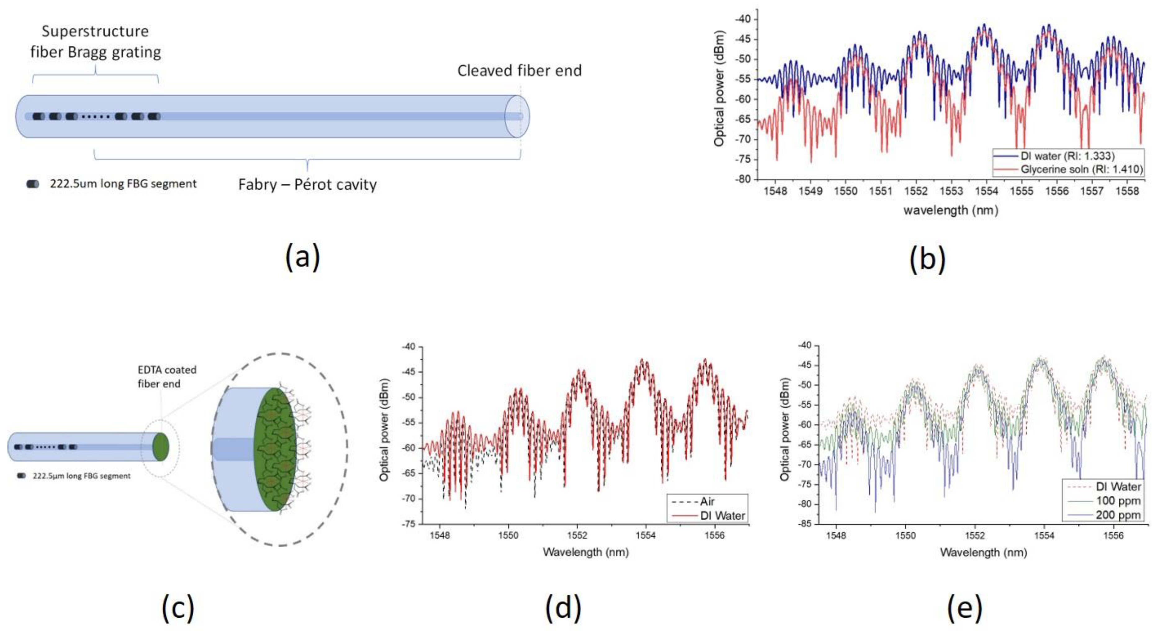
An example of a sensor (Tan et al., 2018 [20]) can be used to demonstrate this concept. A fiber end configuration refractometer probe was demonstrated by cascading an FBG with a right-angle cleaved fiber end resulting in a Fabry-Perot cavity. The interference pattern of the sensor evolves with changes in ambient RI. Detailed operating principles of the sensor can be found in the reference and is not a topic of this discussion and hence omitted. The refractometer showed in Figure 1 is found to be sensitive to ambient RI changes. However, upon application of an Ethylenediaminetetraacetic acid (ETDA) coating on the sensing surface of the sensor, the refractometer ceases to be sensitive to ambient RI changes and instead directly measures the RI of the EDTA coating.
Widely used in chelation therapy for heavy metal poisoning patients, EDTA is a chelating agent for metal ions. Upon binding to a metal ion, the EDTA compound’s physical properties was altered. RI of the chelate differs from the original compound. As the EDTA coating of the demonstrated sensor binds Cd2+ ions, the change in RI is captured by the refractometer which the EDTA coating was applied on. Hence, the observable spectral variation of the optical refractometer is now indicative of the presence of Cd2+ ions.
3. Common Optical Fiber Refractometers
3.1. Fiber End Ratiometer
Reflection at the cleaved end of an optical fiber is a function of the RI mismatch between the optical fiber and the ambient environment according to Fresnel’s law. Therefore, RI of the ambient environment can be determined if the effective RI of the optical fiber is known. However, when this reflected power from a single strand of optical fiber is used to measure RI of the ambient environment, power fluctuation of light that reaches the optical fiber end caused by numerous factors such as bending loss and instability of light source contributes severely to inaccuracy, making it infeasible in real-world applications. To compensate for these inaccuracies, a ratiometer setup was proposed [24,25]. This design consists of two strands of optical fiber guiding light from the same light source split by a 50:50 optical coupler (Figure 2). The propagation path and power of light that reached the end of the two fiber ends are therefore ideally identical.
As one of the fiber ends is interfaced with an ambient environment of known RI and the other in a test substance, the ratio of their reflected power can be used to determine the RI of the test substance.
3.2. Tapered Microfiber
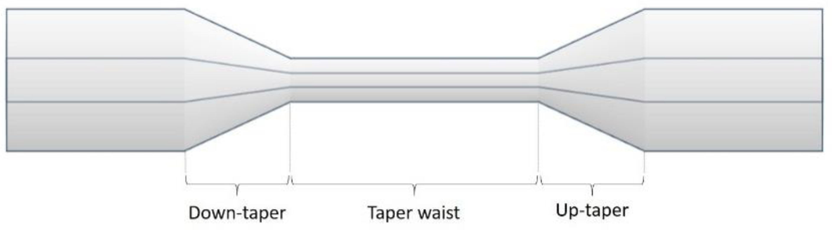
Tapered microfiber is fabricated by gradually reducing the diameter of a standard optical fiber along a short length. This is usually achieved by heating a point of the fiber beyond its melting point while being pulled apart with precision-controlled translation stages [26,27].
The most fundamental microfibers sensors as illustrated in Figure 3, are generally fabricated to operate in single mode from single mode fiber, while works on multimode fibers have been reported [28,29,30]. Given a suitable design of tapered slope and waist and length, a portion of the fiber guided optical power extends out of the fiber structure into the ambient environment as evanescent wave. The extent of light that propagates out of the fiber structured and guided along the fiber is determined by wavelength of light, slope of taper, and diameter of waist [31]. This structure is known as a biconical microfiber, the most basic of microfiber RI sensors [32]. Tapered microfiber can be of an adiabatic or nonadiabatic profile. Design considerations are well discussed elsewhere [33,34].
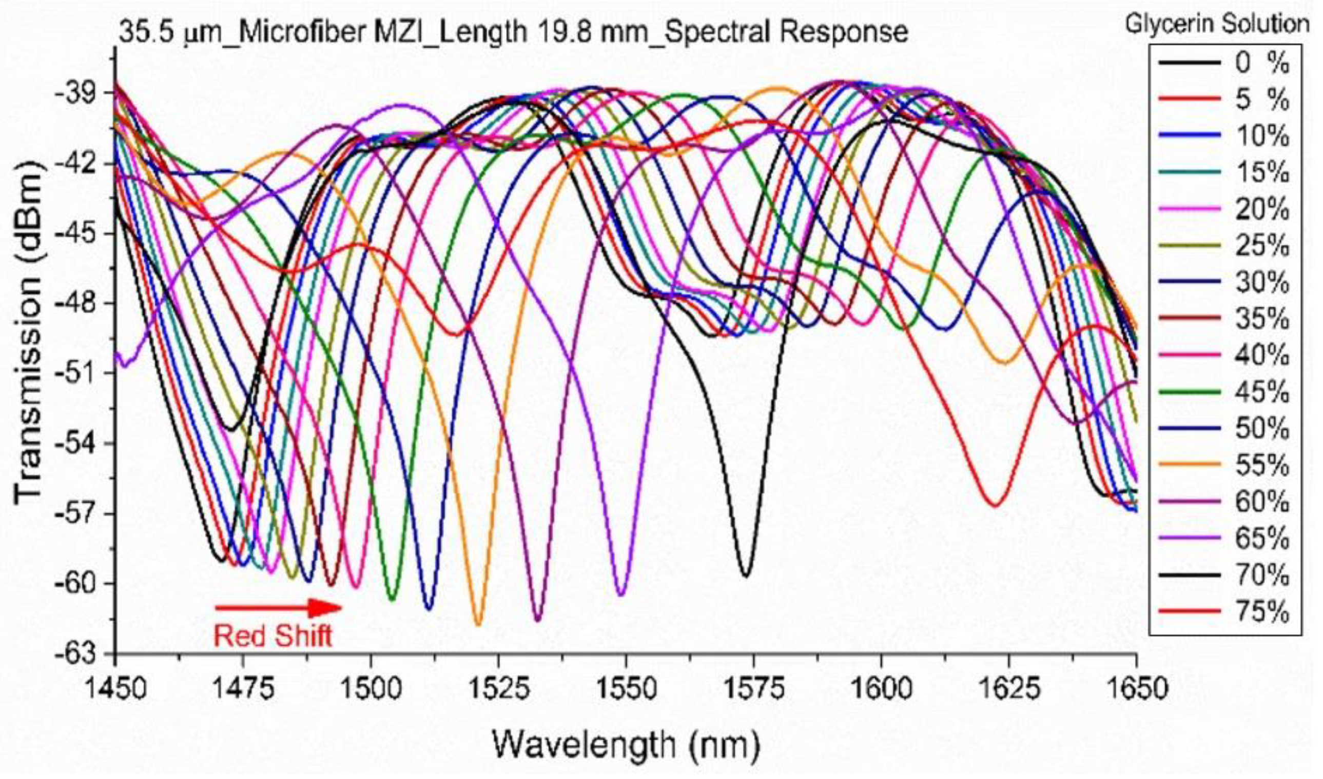
A nonadiabatic profile can be designed so that mainly HE11 and HE12 modes are excited at the tapered region [35]. As fundamental guided mode of light propagates through the pristine region of the fiber towards the down taper, it couples into multiple modes with most power in HE11 and HE12 modes. These two modes propagate partly out of the fiber structure in different extents along the taper waist. The fiber modes with different exposure to the ambient environment will then experience different propagation constant before they couple back into the single mode fiber at the up-taper region with a phase difference resulting in a Mach-Zehnder interference (MZI) pattern (Figure 4). The transmission MZI spectrum of the sensor undergoes phase shift when RI mismatch of the ambient environment and the optical fiber varies, caused by changes in propagation constant of the respective interfering modes.
Many RI sensors employing such scheme have been reported with variations such as different taper lengths, fiber material, taper waist [13], and cascading tapers [37]. The improvements being pursued by work on such sensing scheme includes higher sensitivity [36] and larger free spectra range. However, these sensors, being heavily modified from standard fibers, suffer from inherent disadvantages such as structure fragility and cross sensitivity to temperature and strain.
3.3. Cladding Modified Fiber
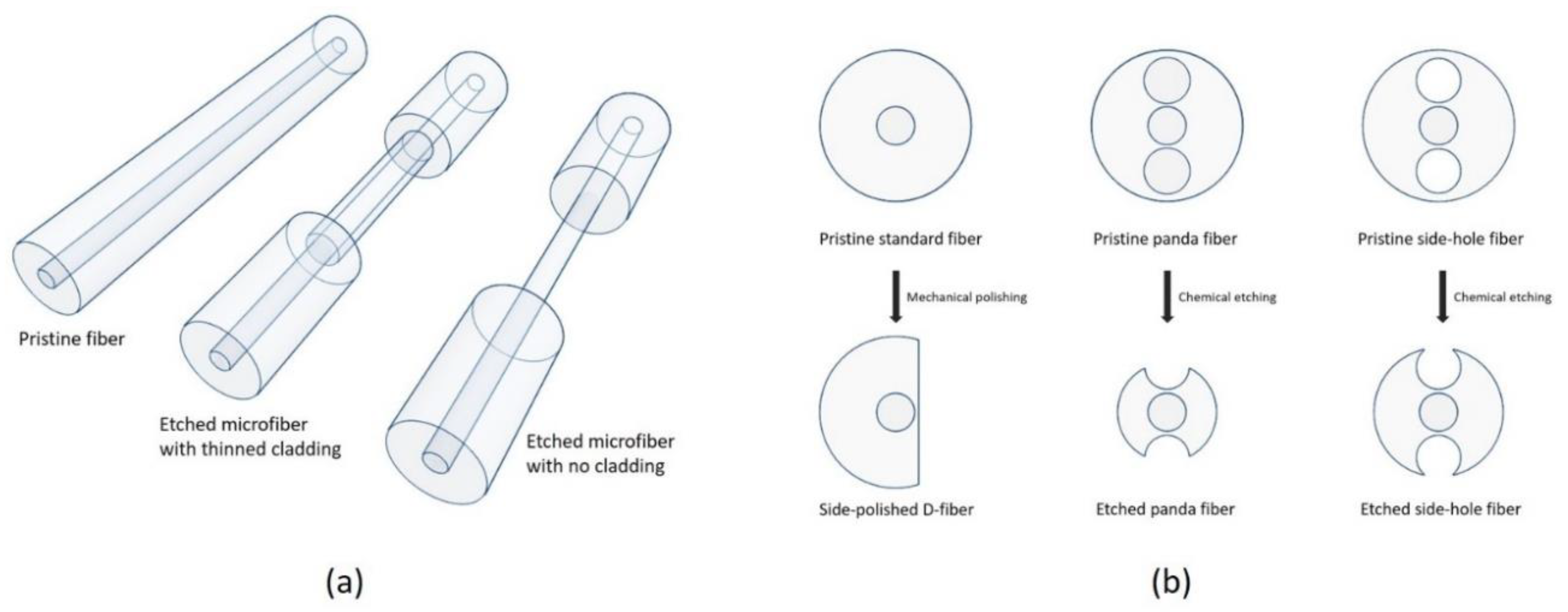
Like tapered microfibers, the concept of cladding modification is to sensitize the fiber to ambient RI fluctuation by extending the guided modes into the ambient environment. This is done in this class of refractometer schemes, usually by removing whole or part of the fiber cladding. Etched microfibers are well studied refractometers similar to tapered microfibers that the standard fiber is reduced to a small diameter down to a few micrometers. The cladding is symmetrically and uniformly removed by etching in strong acids (e.g., hydrofluoric acid). Sensitivity of these sensors can be controlled by the degree of etching and can be made ultra-sensitive when etched close to the core of the fiber or have the fiber cladding entirely removed [38].
Other forms of cladding modified fiber have claddings removed nonuniformly by means inclusive but not limited to etching nonstandard fibers [16,39], side polishing [40,41,42] or fabrication of the fibers using preform milled into special shapes [19,43].
In general, these sensors are interferometric. For uniformly etched devices as seen in Figure 5a, an interference similar to that of a tapered microfiber is formed. As light propagates from the unmodified length of the optical fiber to the cladding reduced/removed portion, higher order modes (ambient exposed modes) are excited and propagates along the length of the modified fiber. These modes propagate at different propagation constant due to the RI mismatch in the medium they are propagating in. Therefore, the modes couples back into the fiber in different phase, forming an MZI. On the other hand, the non-uniformly etched fiber devices as in Figure 5b are also interferometric but the interfering modes are generally the orthogonal polarization modes guided in the fiber core, partially exposed to the ambient environment in one of the polarization axis more than the other due to the fiber’s physical structure.
3.4. Fiber Grating Sensors
Fiber gratings are microstructures inscribed into an optical fiber that interact with the fiber guided light, diffracting the incident light [44]. These structures contain periodically modulated RI along the fiber, usually in its core, induced by a few methods such as ultra-violet light exposure and femtosecond laser pulse irradiation. There are two main types of gratings, long period fiber gratings (LPFG) and fiber Bragg gratings (FBG), and both can be employed in optical fiber refractometers.
3.4.1. Long Period Fiber Grating
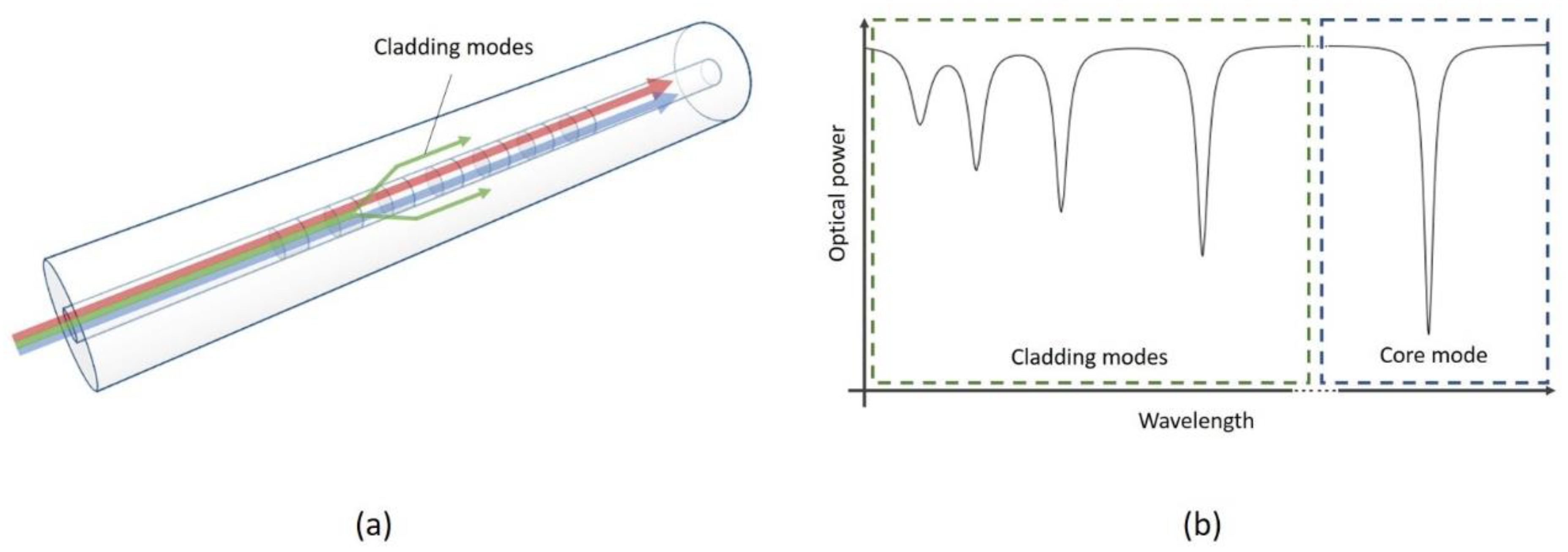
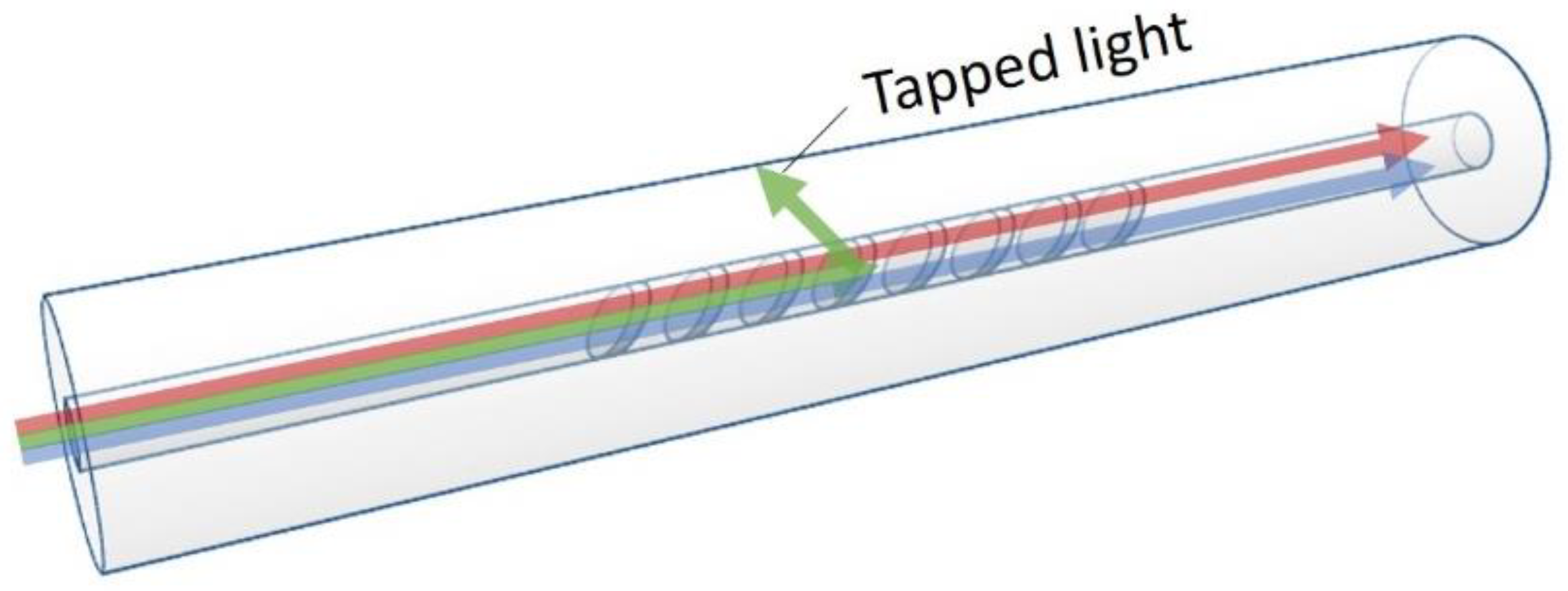
As its name suggest, the grating period of the LPFG is long (see Figure 6), relative to FBGs, general in the sub-millimeter range. LPFGs are inherently sensitive to ambient RI as it is a device designed to couple core guided modes into the fiber cladding as forward propagating cladding modes. These cladding modes are guided within the cladding with the principle of total internal reflection satisfied at the cladding to ambient environment boundary due to the RI mismatch. Some of the higher order cladding modes also extends out of the fiber, directly interacting with the ambient environment. As the total internal reflection conditions of all cladding modes and propagation constant of the higher order modes are a strong function of the ambient RI, the resulting transmission spectrum of the LPFG is representative of ambient RI change [45].
A rise in ambient RI results in higher loss for the LPFG’s cladding modes, especially for the higher order cladding modes, resulting in spectral change. The rise also causes higher effective RI for all the cladding modes resulting in a spectral red shift. These properties of the LPFG have been exploited for RI sensing [46,47,48]. Sensitivity of the grating can be improved to suit specific applications with a series of techniques discussed, including parameter tuning [49] and coating on the fiber surface [50,51].
3.4.2. Fiber Bragg Grating
FBGs are grating with grating period in the sub-micrometer range [52]. These gratings are designed to reflect light of a specific narrow wavelength band with center wavelength called the Bragg wavelength. A normal uniform FBG is not inherently sensitive to ambient RI as it mostly influences the core guided modes that are tightly confined in the fiber core with no interaction with the ambient environment. However, fiber sensitization techniques such as fiber tapering [53,54] and cladding modification [55,56] can be employed to sensitize the Bragg grating.
A special FBG known as the tilted FBG (TFBG) shown in Figure 7, can be used without modification for RI sensing [57,58]. When a FBG’s index modulation planes was inscribed in the fiber core at an angle to the fiber core, core guided light is coupled by the grating into the cladding as loosely guided cladding modes. Similar to LPFG’s cladding modes, these cladding modes of the TFBG can interact with the fiber’s ambient environment resulting in a discernable spectrum change.
4. Common Surface Coating Techniques
An optical fiber can be coated with materials using different methods. Selection of coating techniques depends on the nature of coating material, material of optical fiber, and physical structure of the surface to be coated. This section reviews five of the most common techniques applicable for coating optical fiber refractometers with metal ion trapping or chelating materials.
4.1. Drop Casting
Drop casting is the simplest method of coating. The technique can be used for coating a length of optical fiber with both particles and nanosheets. For particles, the coating material is first mixed with a suitable solvent with sonification. For non-soluble materials, a well-mixed suspension can be used. Nanosheets are prepared with suitable methods and suspended in a suitable solvent. The optical fiber surface is to be prepared by removal of any protective coating and cleaned with a solvent. The solution can then be dropped onto the fiber surfaces. The fiber surface is now coated and to be left to dry, which can be encourage by heating. This is a suitable method only for coating with very small nanoparticles where surface forces are enough to adhere the coating onto the fiber surface, or when the requirement of application is not stringent on adhesion strength. Depending on applications of the sensor, the simplicity of this coating method often outweighs its disadvantages.
4.2. Dip Coating
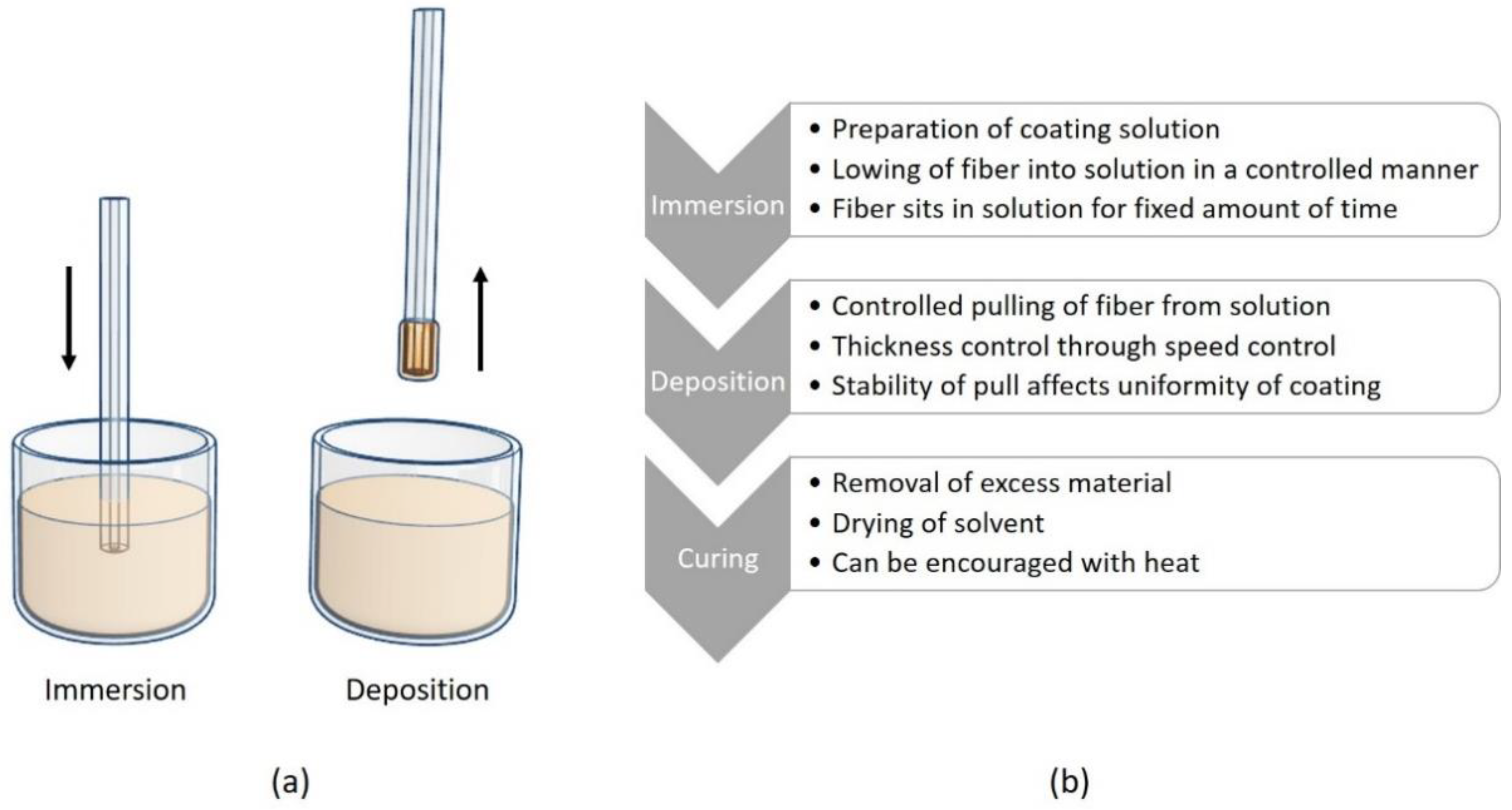
Dip coating of an optical fiber as shown in Figure 8, can be carried out either on the fiber end or along the fiber length [59]. It typically involves three steps. Before the actual process, the fiber surface is first prepared by removal of protective coating and cleaning with a solvent. The coating solution is prepared in a suitable process depending on the material.
The first step of immersion involves lowering the fiber into the coating solution in a controlled manner and leaving it to sit for a fixed amount of time allowing the material to cling onto the fiber surface. The fiber is then pulled out of the solution at a uniform speed. Uniformity and thickness of coating to be deposited is determined by the acceleration and speed of pull respectively. Lastly, excess material can drip off naturally and coated material cured with a suitable curing method such as application of heat or ultra-violet light. With precise control in each of the three steps, it is possible to deposit a monolayer or specific thickness of material onto the fiber surface.
4.3. Optical Deposition
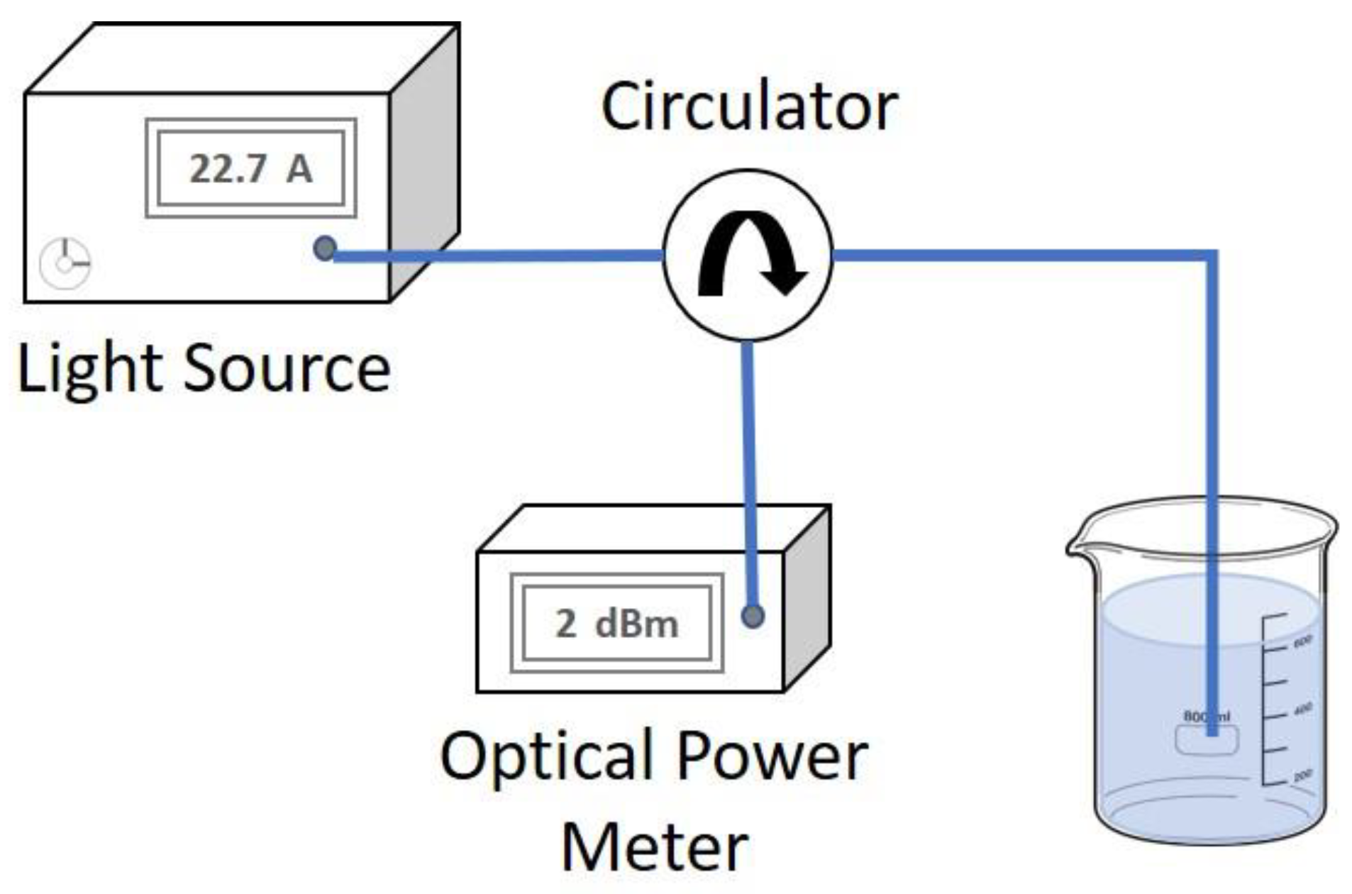
Optical deposition is used to deposit a thin layer of coating material at interface of fiber guided light and the coating solution. Commonly, coating at fiber end finds this technique suitable. The optical deposition set up is depicted in Figure 9.
The optical deposition process can be controlled by regulating the power of light source and deposition time in order to deposit specific amount of coating on the fiber surface. The coating process can also be monitored through the back reflection of light from the fiber end, using a circulator and power meter. Back reflection at the fiber end increases as material adhere to the fiber end. This is true with most coating material of RI higher than that of the optical fiber and is not optically absorbent. Experimentally, it is then possible to optimize the coating process to achieve thickness of coating to a high degree of control. This coating techniques has gained traction as the ideal coating method for fiber ends as demonstrated by many graphene and carbon nanotube deposition applications recently reported.
Interestingly, the mechanism of optical deposition is not fully understood. Reports have proposed two working theories, the first of which suggested that light guided by the optical fiber entering the solution and heats up the solution locally and causes thermophoresis of the solution which pulls coating material towards the fiber surface and adheres to the surface [60,61]. Experts also theorized that the coating material could be captured at the fiber surface by the fiber guided light with optical tweezing effect [62,63].
4.4. Electrospining and Electrospraying
Commonly used to deposit polymer nano fibers or nano particles on a substrate, electrospinning and electrospraying are both electrohydrodynamic processes which can be used to deposit thin layers of conducting polymers onto optical fiber surface. Some of these polymers such as polyacetylene and polypyrrole interacts with metal ions and results in a change in material optical properties [64]. The electrospinning process can also be modified to deposit nano structured materials, allowing more design freedom of coating material. One example of such modification is coaxial electrospinning techniques that combines two materials in a core-coating structure [65,66]. Likewise, coaxial electro spraying enables fabrication of composite nanostructured particles of two materials [67,68].
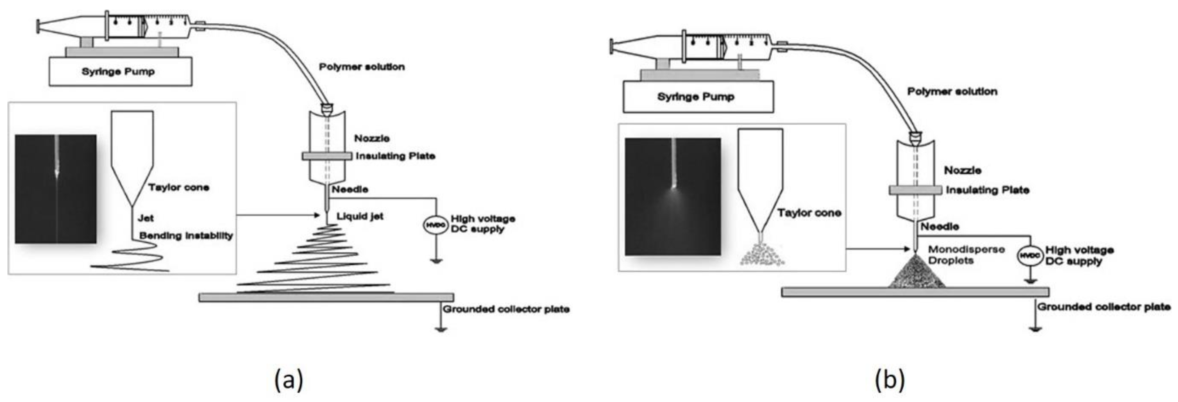
Although electrospinning and electrospraying is used to deposit nano fibers and nano particles respectively, the operating principles and set up for the processes are largely the same. In the simplest form as depicted in Figure 10, both the electrospinning and electro spraying process are identical in setup, differing only in some adjustable parameters such as distance between electrodes, applied voltage, and concentration of material solution.
The coating set up generally involves a polymer release mechanism with a control system at the anode, such as a precision pump operated syringe where the metal needle of the syringe act as the electrode. It is to be noted that a reservoir of polymer solution without a pump can also be used as the mechanism of material propulsion is not reliant on external mechanical forces applied. A high voltage DC power supply is used to apply a large potential difference between the needle of the syringe and the grounded surface. This high potential between the needle and the grounded surface causes electrically-charged polymer to propel out of the needle. The solution propels toward the grounded surface either in a viscoelastic jet that elongates into spiraling nanofibers due to charge interactions as the solvent evaporates (electrospinning), or as a dispersed spray of nano particles (electrospraying). The achieved effect of electrospinning or electrospraying is determined by the concentration of polymer solution and potential applied to the system.
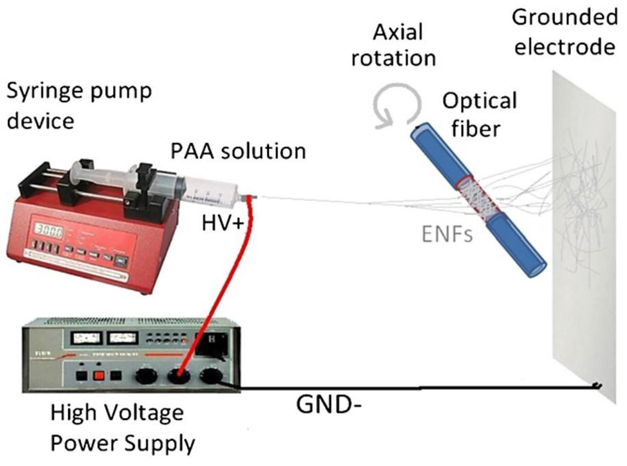
To coat the surface of an optical fiber. The fiber can be placed near the ground surface as demonstrated by Urritia et al. [70]. A rotation of the optical fiber to be coated is to be maintained so as to evenly coat the cylindrical surface fiber surface (Figure 11).
Due to the material nature of the standard optical fiber, silica optical fibers cannot be directly used as ground for the coating process. However, it is possible for special fibers such as side hole fibers with nanowire inserts to be used instead. The electrohydrodynamic process is discussed in depth in [71,72] should the reader be interested in gaining a deeper appreciation of the technique.
4.5. Layer by Layer Deposition
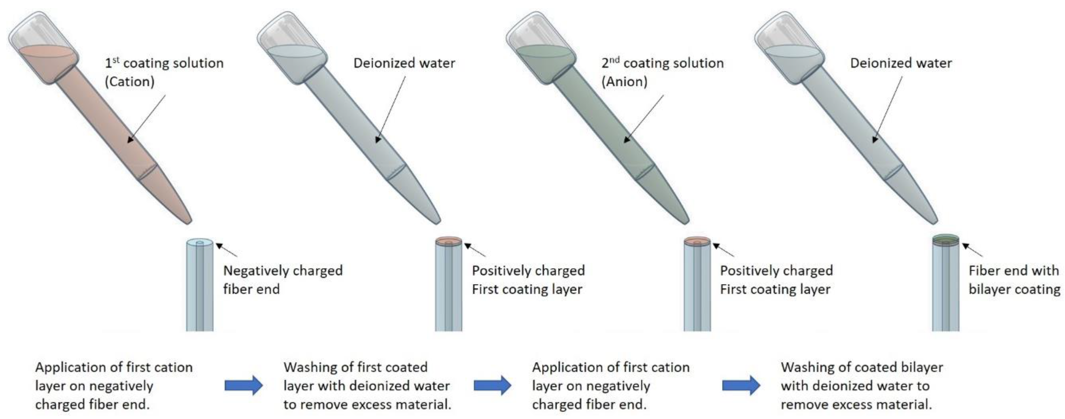
The layer by layer techniques showed in Figure 12 is used in fabrication of thin film coating by stacking layers of opposingly charged materials onto a substrate. Each layer adheres to the others including the substrate due to the resulting electrostatic attraction. Each layer can be deposited onto the assembly using different suitable methods including drop casting, dip coating, and spray coating. In depth details on the method and relevant considerations were first discussed by Gero Decher [73].
The layer by layer deposition of thin film onto optical fiber generally follows the following order of processes. The substrate, a surface of the optical fiber, needs to be prepared by removal of its protective coating and cleaned with a suitable solvent. For the first layer of polymer to be electrostatically attracted to the fiber surface, the fiber must be treated to gain a charged surface. The fiber surface is then exposed to an opposingly charged material, positive if the optical fiber is negatively charged, by a suitable coating method. A mono layer of the material will electrostatically adhere to the substrate. The coated fiber is to be rinsed with de-ionized water to remove excess coating material that not adhered to the fiber, then left to dry. If another layer were to be applied, material of an opposing charge as the previous layer must be used. Subsequent layers can add by repeating the same process until the desired number of layers is achieved.
5. Recent Demonstration of Surface Functionalized Refractometer for Metal Ion Detection
In the past decade, researchers working on solutions of heavy metal ion detection have moved from bulk optics to fiber technologies. The emphasis on ease of implementation and real-world applications had fostered a greater interest in optical fiber as a solution for the sensor community, especially in the past five years. A smaller group within the community have been actively seeking sensor design based on surface modification of simple optical fiber refractometer schemes. This section provides an overview of these works. Amongst the heavy metal group, reports (listed in Table 1) were made for the detection of cadmium, cobalt, copper, iron, lead, mercury, and nickel.
For clarity of discussion, we review work done for the detection of each heavy metal systematically.
5.1. Detection of Cadmium Ion
Benounis et al. [74] coated Calixarene to a portion of a plastic cladding optical fiber with a segment stripped of its cladding. The coating was applied by repeated dipping until multiple layers of coating amounting to 1 μm was achieved. When exposed to solution of Cd2+, light confinement of the fiber at the coating portion weakens and power was lost. Hence, detection of Cd2+ is through measurement of transmitted power loss. A detection lower limit of 10−4 μM was achieved. Tan et al. [20] fabricated a interferometric refractometer with a Fabry-Perot cavity between the cleaved end of a standard fiber and a superstructure FBG. The interference pattern resulted from the cavity varies with the change in cleaved fiber end reflectivity which is a function of the ambient environment RI. Ethylenediaminetetraacetic acid (EDTA) was coated onto the fiber end by optical deposition cum chemical process for the chelation of Cd2+ ions. A lower detection limit of 10 ppm was reported.
5.2. Detection of Cobalt Ion
In the same work from Benounis et al. [74] that reported Cd2+ detection, the same sensor was also found to be sensitive to Co2+ with a detection lower limit of 10−3 μM. The selectivity of the metal detection sensor in this work is hence not metal ion discriminatory, which is a common problem to many such sensors. In fact, the sensor has also shown to be sensitive to Cu2+ ions with detection limit of 1 μM. However, the sensitivity of the sensor is different for the three metal ions, resulting in difference in detection limit of each metal ion type due to complexation constant and reaction kinetics of forming metal hydroxides.
5.3. Detection of Copper Ion
Mahendra et al. [77] demonstrated a fiber end reflectance sensor physically interfaced with α-Benzoinoxime immobilized on Amberlite XAD-2 polymer, a hydrophobic crosslinked polystyrene copolymer resin. Reflectance was monitored as the set up was exposed to Cu2+ ions. In this work a lower detection limit of 5 ppm was reported. Tran et al. [82] reported a cladding stripped fiber tip with core surfaced functionalized with chitosan-conjugated EDTA that was exposed to solution of Cu2+, acting as a liquid cladding. The numerical aperture of the fiber with liquid cladding varies as concentration of Cu2+ in the liquid cladding changes. Hence, variation in Cu2+ concentration was measured by power transmittance change of the fiber. A lower detection limit of 1.62 nM was achieved.
5.4. Detection of Iron Ion
Detection of Fe3+ was reported by Yap et al. [85] by functionalizing a single taper microfiber interferometer with nitrogen- and sulfur-codoped carbon dots through a chemical process. As the doped carbon dots chelates Fe3+ ions, the transmission spectrum of the ultrasensitive tapered fiber refractometer exhibits a spectrum shift according to the RI change due to the chelation process. A maximum sensitivity of 0.0061 nm/(μg/L) was reported.
5.5. Detection of Lead Ion
Liu et al. [76] coated a TFBG sensor with black phosphorus nanosheets. The nanosheet was deposited onto the fiber surface using a modified layer-by-layer technique while its transmission spectrum was monitored. The Pb2+ sensor was found have achieved a lower detection limit of 0.25 ppb with maximum sensitivity of 0.5 × 10⁻³ dB/ppb. Yap et al. [84] functionalized a tapered microfiber MZI refractometer with l-glutathione using a chemical process. The sensor is exclusively sensitive to lead ions and has achieved a lower detection limit of 5 μg/L. Lastly, Yulianti et al. [86] applied a thin coating of chitosan on the cleaved fiber end of a standard single mode fiber by dip coating. The thin layer of chitosan forms an interferometer due to the RI mismatch at its 2 interfaces. The property of interference was reported to change with the chelation of heavy metal ions. A sensitivity of 0.177 dB/ppm to Pb2+ was noted. However, due to the nature of chitosan, the sensor is cross sensitive to other metal ions. The same sensor measured concentration of Hg2+ and Ni2+ with sensitivity of 0.215 dB/ppm and 0.1445 dB/ppm respectively. This exemplified the multiple metal ion cross-sensitivity limitation of such sensors once again.
5.6. Detection of Mercury Ion
A LPFG coated with polyelectrolyte for sensitivity enhancement and gold nanoparticles for chelation of Hg2+ was fabricated by Tan et al. [81]. The coating was immobilized onto the LPFG surface by electrostatic self-assembly. Upon exposure to Hg2+ ions, resonance wavelength of the surface modified LPFG shifted and a transmission power increment was observed. The authors further confirmed the contribution of Hg2+ ions to the observed changes by conducting the same experiment with an LPFG that was not coated. In the control experiment, no changes in both resonance wavelength and transmission power was noted. The lowest detectable concentration of Hg2+ reported in the work was 0.5 ppm. Zhang et al. [87] demonstrated a interferometric RI sensor by cascading a FBG with a short length of no core fiber at the fiber end. The no core fiber was coated with a bilayer coating made up of chitosan and poly acrylic acid in a layer by layer deposition process. By observing the spectrum shift of the resulting interference pattern when exposed to Hg2+ ions, a maximum sensitivity of 0.0178 nm/μM was achieved in the range of 100–500 μM. Zhong et al. [88] coated a Hg2+ sensitive film prepared with layer by layer process using tris [2-(4-phenyldiazenyl) phenylaminoethoxy] cyclotriveratrylene chromophore, poly dimethyl diallyl ammonium chloride polycation and polyacrylic acid polyanion onto the polished surface of a D-shaped polymer fiber. A lower detection limit of 0.1 mg/L was reported.
5.7. Detection of Nickel Ion
Lin et al. [75] presented a MZI refractometer formed by two fiber taper along a strand of standard optical fiber. The two tapers were functionalized with a multi-layer film of chitosan, multi-walled carbon nanotubes, and poly acrylic acid directly deposited into the tapers with layer-by-layer assembly technique. By observing the transmission spectrum shift when the tapers were exposed to Ni2+ ions, a maximum sensitivity of 56.5 dB/mM in the range of 0.3 to 0.7 mM was noted. Raghunandhan et al. reported a series of work on Ni2+ ion detection based on three different interferometric RI sensors and different coating materials. One work reported a MZI formed by splicing a no-core fiber between two standard single mode fibers [78]. The no-core fiber region was sensitized to Ni2+ ions using bilayer of chitosan and poly acrylic acid. This sensor achieved a maximum sensitivity of 0.05537 nm/μM and lower detection limit of >0.1671 μM. In another work, the based refractometer was fabricated by splicing a length of no-core fiber to the fiber end of a length of single mode fiber [79]. The no-core fiber was coated with Meso-Tetra(4-carboxyphenyl)porphine in a chemical process. The sensor was reported to have a sensitivity of 121.03 nm/mM. In the latest work from Raghunandhan et al. [80], an interferometric RI sensor fabricated by splicing a length of photonics crystal fiber between single mode fibers was demonstrated. The photonic crystal fiber was coated with nickel-adsorbed chitosan crosslinked with epichlorohydrin using dip coating process. A maximum sensitivity of 0.0632 nm/μM and lower detection limit of 0.57 μM was achieved. Lastly, Yang et al. [83] formed a ratiometer between a FBG reflection and its fiber end reflection. The sensor fiber end was coated with bilayers of chitosan and poly acrylic acid using layer by layer assembly. By comparing reflected power level of the FBG and fiber end broadband reflection, the sensor achieved a measurement sensitivity of 40.52 dB/mM for Ni2+ ions concentration.
6. Conclusions
The versatility of optical fiber refractometers enabled applications for detection of various heavy metal ions with appropriate choices of surface coating. This paper provided an overview of several reported metal ion sensor implemented, introduced some common optical fiber RI sensors in their most basic configurations suitable for surface coating, and discussed popular surface coating techniques. As compared to the vastness of photonics research in metal ion detection, surface coated optical refractometers are not as well studied. The operating principles of these sensors are remarkably simple. At the same time, due to the maturity of both optical fiber RI sensing and surface coating technology, these sensors that were proposed have great potential to be translated into affordable commercial products. However, there are still hurdles to overcome by the sensor community in this area, addressing the limitations still faced by the reported sensors such as selectivity of analyte, cross sensitivity to environmental physical attributes (i.e., temperature and pressure changes), and requirement for bulky interrogation systems. Overall, it is logical to conclude that this field deserve more attention from researchers to accelerate the path to maturity of this technology.
Funding
This research received no external funding.
Conflicts of Interest
The authors declare no conflict of interest.
References
- Van Heel, A. Newton’s Work on Geometrical Optical Aberrations. Nature 1953, 171, 305. [Google Scholar] [CrossRef] [PubMed]
- Van Heel, A.C. A new method of transporting optical images without aberrations. Nature 1954, 173, 39. [Google Scholar] [CrossRef]
- Schultz, P.C. Making the first low loss optical fibers for communications. In Proceedings of the 36th European Conference and Exhibition on Optical Communication, Torino, Italy, 19–23 September 2010; pp. 1–9. [Google Scholar]
- Artiola, J.; Brusseau, M. The Role of Environmental Monitoring in Pollution Science. In Environmental and Pollution Science; Elsevier: Amsterdam, The Netherlands, 2019; pp. 149–162. [Google Scholar]
- Luan, I.O.B. Singapore water management policies and practices. Int. J. Water Resour. Dev. 2010, 26, 65–80. [Google Scholar] [CrossRef]
- Mekonnen, M.M.; Hoekstra, A.Y. Four billion people facing severe water scarcity. Sci. Adv. 2016, 2, e1500323. [Google Scholar] [CrossRef] [PubMed] [Green Version]
- Duruibe, J.O.; Ogwuegbu, M.; Egwurugwu, J. Heavy metal pollution and human biotoxic effects. Int. J. Phys. Sci. 2007, 2, 112–118. [Google Scholar]
- Bürck, J.; Conzen, J.-P.; Ache, H.-J. A fiber optic evanescent field absorption sensor for monitoring organic contaminants in water. Fresenius J. Anal. Chem. 1992, 342, 394–400. [Google Scholar] [CrossRef]
- Dybko, A.; Wroblewski, W.; Maciejewski, J.; Romaniuk, R.S.; Brzozka, Z. Fiber optic probe for monitoring of drinking water. In Proceedings of the Chemical, Biochemical and Environmental Fiber Sensors IX, Munich, Germany, 30 May 1997; pp. 361–366. [Google Scholar]
- Oehme, I.; Wolfbeis, O.S. Optical sensors for determination of heavy metal ions. Microchim. Acta 1997, 126, 177–192. [Google Scholar] [CrossRef]
- Wo, J.; Wang, G.; Cui, Y.; Sun, Q.; Liang, R.; Shum, P.P.; Liu, D. Refractive index sensor using microfiber-based Mach–Zehnder interferometer. Opt. Lett. 2012, 37, 67–69. [Google Scholar] [CrossRef]
- Ji, W.B.; Liu, H.H.; Tjin, S.C.; Chow, K.K.; Lim, A. Ultrahigh sensitivity refractive index sensor based on optical microfiber. IEEE Photonics Technol. Lett. 2012, 24, 1872–1874. [Google Scholar] [CrossRef]
- Ji, W.B.; Tan, Y.C.; Lin, B.; Tjin, S.C.; Chow, K.K. Nonadiabatically tapered microfiber sensor with ultrashort waist. IEEE Photonics Technol. Lett. 2014, 26, 2303–2306. [Google Scholar] [CrossRef]
- Jing, N.; Zheng, J.; Zhao, X.; Teng, C. Refractive index sensing based on a side-polished macrobending plastic optical fiber. IEEE Sens. J. 2014, 15, 2898–2901. [Google Scholar] [CrossRef]
- Iadicicco, A.; Cusano, A.; Cutolo, A.; Bernini, R.; Giordano, M. Thinned fiber Bragg gratings as high sensitivity refractive index sensor. IEEE Photonics Technol. Lett. 2004, 16, 1149–1151. [Google Scholar] [CrossRef]
- Li, J.; Wang, H.; Sun, L.-P.; Huang, Y.; Jin, L.; Guan, B.-O. Etching Bragg gratings in Panda fibers for the temperature-independent refractive index sensing. Opt. Express 2014, 22, 31917–31923. [Google Scholar] [CrossRef] [PubMed] [Green Version]
- Chong, J.H.; Shum, P.; Haryono, H.; Yohana, A.; Rao, M.; Lu, C.; Zhu, Y. Measurements of refractive index sensitivity using long-period grating refractometer. Opt. Commun. 2004, 229, 65–69. [Google Scholar] [CrossRef]
- Shen, F.; Wang, C.; Sun, Z.; Zhou, K.; Zhang, L.; Shu, X. Small-period long-period fiber grating with improved refractive index sensitivity and dual-parameter sensing ability. Opt. Lett. 2017, 42, 199–202. [Google Scholar] [CrossRef] [PubMed] [Green Version]
- Tan, R.X.; Ho, D.; Tse, C.H.; Tan, Y.C.; Yoo, S.W.; Tjin, S.C.; Ibsen, M. Birefringent Bragg Grating in C-Shaped Optical Fiber as a Temperature-Insensitive Refractometer. Sensors 2018, 18, 3285. [Google Scholar] [CrossRef] [Green Version]
- Tan, R.; Yap, S.; Tan, Y.; Tjin, S.; Ibsen, M.; Yong, K.; Lai, W. Functionalized fiber end superstructure fiber bragg grating refractive index sensor for heavy metal ion detection. Sensors 2018, 18, 1821. [Google Scholar] [CrossRef] [Green Version]
- Xu, W.; Huang, X.G.; Pan, J.S. Simple fiber-optic refractive index sensor based on fresnel reflection and optical switch. IEEE Sens. J. 2012, 13, 1571–1574. [Google Scholar] [CrossRef]
- Shen, Y.-R. The Principles of Nonlinear Optics; Wiley-Interscience: New York, NY, USA, 1984; p. 575. [Google Scholar]
- Agrawal, G.P. Nonlinear fiber optics. In Nonlinear Science at the Dawn of the 21st Century; Springer: Berlin/Heidelberg, Germany, 2000; pp. 195–211. [Google Scholar]
- Su, H.; Huang, X.G. Fresnel-reflection-based fiber sensor for on-line measurement of solute concentration in solutions. Sens. Actuators B Chem. 2007, 126, 579–582. [Google Scholar] [CrossRef]
- Kim, C.-B.; Su, C.B. Measurement of the refractive index of liquids at 1.3 and 1.5 micron using a fibre optic Fresnel ratio meter. Meas. Sci. Technol. 2004, 15, 1683. [Google Scholar] [CrossRef]
- Villatoro, J.; Monzón-Hernández, D.; Mejía, E. Fabrication and modeling of uniform-waist single-mode tapered optical fiber sensors. Appl. Opt. 2003, 42, 2278–2283. [Google Scholar] [CrossRef] [PubMed]
- Brambilla, G. Optical fibre nanowires and microwires: A review. J. Opt. 2010, 12, 043001. [Google Scholar] [CrossRef]
- Wang, P.; Brambilla, G.; Ding, M.; Semenova, Y.; Wu, Q.; Farrell, G. High-sensitivity, evanescent field refractometric sensor based on a tapered, multimode fiber interference. Opt. Lett. 2011, 36, 2233–2235. [Google Scholar] [CrossRef] [PubMed]
- Rahman, H.A.; Harun, S.W.; Yasin, M.; Phang, S.W.; Damanhuri, S.S.A.; Arof, H.; Ahmad, H. Tapered plastic multimode fiber sensor for salinity detection. Sens. Actuators A Phys. 2011, 171, 219–222. [Google Scholar] [CrossRef]
- Biazoli, C.R.; Silva, S.; Franco, M.A.; Frazão, O.; Cordeiro, C.M. Multimode interference tapered fiber refractive index sensors. Appl. Opt. 2012, 51, 5941–5945. [Google Scholar] [CrossRef] [PubMed] [Green Version]
- Latifi, H.; Zibaii, M.I.; Hosseini, S.M.; Jorge, P. Nonadiabatic tapered optical fiber for biosensor applications. Photonic Sens. 2012, 2, 340–356. [Google Scholar] [CrossRef]
- Tan, R.X.; Yap, S.H.K.; Tjin, S.C. Fiber gratings enabled interrogation of Mach-Zehnder interferometer tapered fiber sensor. In Proceedings of the 2017 Conference on Lasers and Electro-Optics Pacific Rim (CLEO-PR), Singapore, 31 July–4 August 2017; pp. 1–3. [Google Scholar]
- Chen, G.Y.; Ding, M.; Newson, T.; Brambilla, G. A review of microfiber and nanofiber based optical sensors. Open Opt. J. 2013, 7, 32–57. [Google Scholar] [CrossRef]
- Tong, L.; Zi, F.; Guo, X.; Lou, J. Optical microfibers and nanofibers: A tutorial. Opt. Commun. 2012, 285, 4641–4647. [Google Scholar] [CrossRef]
- Kieu, K.Q.; Mansuripur, M. Biconical fiber taper sensors. IEEE Photonics Technol. Lett. 2006, 18, 2239–2241. [Google Scholar] [CrossRef]
- Ahsani, V.; Ahmed, F.; Jun, M.B.; Bradley, C. Tapered Fiber-Optic Mach-Zehnder Interferometer for Ultra-High Sensitivity Measurement of Refractive Index. Sensors 2019, 19, 1652. [Google Scholar] [CrossRef] [Green Version]
- Tian, Z.; Yam, S.S.-H.; Barnes, J.; Bock, W.; Greig, P.; Fraser, J.M.; Loock, H.-P.; Oleschuk, R.D. Refractive index sensing with Mach–Zehnder interferometer based on concatenating two single-mode fiber tapers. IEEE Photonics Technol. Lett. 2008, 20, 626–628. [Google Scholar] [CrossRef]
- Namiq, M.F.; Ibsen, M. Simple technique of determining the fibre diameter during etching. Opt. Express 2018, 26, 32908–32917. [Google Scholar] [CrossRef] [PubMed]
- Tang, H.; Zhu, J.; Yin, H.; Wang, R.; Wang, H.; Yu, B. Optical fiber refractometer based on etched-stress applying parts PANDA fiber. IEEE Photonics Technol. Lett. 2014, 26, 1356–1359. [Google Scholar] [CrossRef]
- De-Jun, F.; Mao-Sen, Z.; Liu, G.; Xi-Lu, L.; Dong-Fang, J. D-shaped plastic optical fiber sensor for testing refractive index. IEEE Sens. J. 2014, 14, 1673–1676. [Google Scholar] [CrossRef]
- Song, Y.-W.; Yamashita, S.; Goh, C.S.; Set, S.Y. Carbon nanotube mode lockers with enhanced nonlinearity via evanescent field interaction in D-shaped fibers. Opt. Lett. 2007, 32, 148–150. [Google Scholar] [CrossRef]
- Qazi, H.H.; Memon, S.F.; Ali, M.M.; Irshad, M.S.; Ehsan, S.A.; Salim, M.R.B.; Mohammad, A.B.B.; Zulkifli, M.Z.; Idrees, M. Surface roughness and the sensitivity of D-shaped optical fibre sensors. J. Mod. Opt. 2019, 66, 1244–1251. [Google Scholar] [CrossRef]
- Li, J.; Sun, L.-P.; Gao, S.; Quan, Z.; Chang, Y.-L.; Ran, Y.; Jin, L.; Guan, B.-O. Ultrasensitive refractive-index sensors based on rectangular silica microfibers. Opt. Lett. 2011, 36, 3593–3595. [Google Scholar] [CrossRef]
- Hill, K.O.; Meltz, G. Fiber Bragg grating technology fundamentals and overview. J. Lightwave Technol. 1997, 15, 1263–1276. [Google Scholar] [CrossRef] [Green Version]
- Vasil’ev, S.A.; Dianov, E.M.; Medvedkov, O.I.; Protopopov, V.N.; Costantini, D.; Iocco, A.; Limberger, H.; Salathe, R. Properties of the cladding modes of an optical fibre excited by refractive-index gratings. Quantum Electron. 1999, 29, 65. [Google Scholar] [CrossRef] [Green Version]
- Bhatia, V.; Vengsarkar, A.M. Optical fiber long-period grating sensors. Opt. Lett. 1996, 21, 692–694. [Google Scholar] [CrossRef]
- Duhem, O.; Henninot, J.-F.; Warenghem, M.; Douay, M. Demonstration of long-period-grating efficient couplings with an external medium of a refractive index higher than that of silica. Appl. Opt. 1998, 37, 7223–7228. [Google Scholar] [CrossRef] [PubMed]
- Lee, B.H.; Liu, Y.; Lee, S.B.; Choi, S.S.; Jang, J.N. Displacements of the resonant peaks of a long-period fiber grating induced by a change of ambient refractive index. Opt. Lett. 1997, 22, 1769–1771. [Google Scholar] [CrossRef] [PubMed]
- Shu, X.; Zhang, L.; Bennion, I. Sensitivity characteristics near the dispersion turning points of long-period fiber gratings in B/Ge codoped fiber. Opt. Lett. 2001, 26, 1755–1757. [Google Scholar] [CrossRef] [PubMed]
- Tang, J.-L.; Wang, J.-N. Chemical sensing sensitivity of long-period grating sensor enhanced by colloidal gold nanoparticles. Sensors 2008, 8, 171–184. [Google Scholar] [CrossRef] [PubMed] [Green Version]
- Del Villar, I.; Matias, I.R.; Arregui, F.J. Enhancement of sensitivity in long-period fiber gratings with deposition of low-refractive-index materials. Opt. Lett. 2005, 30, 2363–2365. [Google Scholar] [CrossRef] [PubMed]
- Meltz, G.; Morey, W.W.; Glenn, W. Formation of Bragg gratings in optical fibers by a transverse holographic method. Opt. Lett. 1989, 14, 823–825. [Google Scholar] [CrossRef]
- Gomes, A.D.; Silveira, B.; Warren-Smith, S.C.; Becker, M.; Rothhardt, M.; Frazão, O. Temperature independent refractive index measurement using a fiber Bragg grating on abrupt tapered tip. Opt. Laser Technol. 2018, 101, 227–231. [Google Scholar] [CrossRef] [Green Version]
- Shao, M.; Zang, Y.; Qiao, X.; Fu, H.; Jia, Z.-A. Humidity sensor based on hybrid fiber Bragg grating/abrupt fiber taper. IEEE Sens. J. 2017, 17, 1302–1305. [Google Scholar] [CrossRef]
- Namiq, M.F.; Ibsen, M. Simple Salinity Sensor Based on Cladding-Etched Fibre Bragg Gratings. In Proceedings of the Bragg Gratings, Photosensitivity, and Poling in Glass Waveguides, Sydney, Australia, 5–8 September 2016; p. BM4B.3. [Google Scholar]
- Liao, C.; Wang, Q.; Xu, L.; Liu, S.; He, J.; Zhao, J.; Li, Z.; Wang, Y. D-shaped fiber grating refractive index sensor induced by an ultrashort pulse laser. Appl. Opt. 2016, 55, 1525–1529. [Google Scholar] [CrossRef]
- Guo, T.; Liu, F.; Guan, B.-O.; Albert, J. Tilted fiber grating mechanical and biochemical sensors. Opt. Laser Technol. 2016, 78, 19–33. [Google Scholar] [CrossRef] [Green Version]
- Laffont, G.; Ferdinand, P. Tilted short-period fibre-Bragg-grating-induced coupling to cladding modes for accurate refractometry. Meas. Sci. Technol. 2001, 12, 765. [Google Scholar] [CrossRef]
- Scherino, L.; Giaquinto, M.; Micco, A.; Aliberti, A.; Bobeico, E.; La Ferrara, V.; Ruvo, M.; Ricciardi, A.; Cusano, A. A Time-Efficient Dip Coating Technique for the Deposition of Microgels onto the Optical Fiber Tip. Fibers 2018, 6, 72. [Google Scholar] [CrossRef] [Green Version]
- McNab, G.; Meisen, A. Thermophoresis in liquids. J. Colloid Interface Sci. 1973, 44, 339–346. [Google Scholar] [CrossRef]
- Nicholson, J.; Windeler, R.; DiGiovanni, D. Optically driven deposition of single-walled carbon-nanotube saturable absorbers on optical fiber end-faces. Opt. Express 2007, 15, 9176–9183. [Google Scholar] [CrossRef] [PubMed]
- Kashiwagi, K.; Yamashita, S. Optical deposition of carbon nanotubes for fiber-based device fabrication. Front. Guided Wave Opt. Optoelectron. 2010, 647. [Google Scholar] [CrossRef] [Green Version]
- Zhang, J.; Kim, H.I.; Oh, C.H.; Sun, X.; Lee, H. Multidimensional manipulation of carbon nanotube bundles with optical tweezers. Appl. Phys. Lett. 2006, 88, 053123. [Google Scholar] [CrossRef]
- Deshmukh, M.A.; Shirsat, M.D.; Ramanaviciene, A.; Ramanavicius, A. Composites based on conducting polymers and carbon nanomaterials for heavy metal ion sensing. Crit. Rev. Anal. Chem. 2018, 48, 293–304. [Google Scholar] [CrossRef]
- Zhou, H.; Shi, Z.; Wan, X.; Fang, H.; Yu, D.-G.; Chen, X.; Liu, P. The Relationships between Process Parameters and Polymeric Nanofibers Fabricated Using a Modified Coaxial Electrospinning. Nanomaterials 2019, 9, 843. [Google Scholar] [CrossRef] [Green Version]
- Wang, M.; Hai, T.; Feng, Z.; Yu, D.-G.; Yang, Y.; Annie Bligh, S. The relationships between the working fluids, process characteristics and products from the modified coaxial electrospinning of zein. Polymers 2019, 11, 1287. [Google Scholar] [CrossRef] [Green Version]
- Liu, Z.-P.; Zhang, L.-L.; Yang, Y.-Y.; Wu, D.; Jiang, G.; Yu, D.-G. Preparing composite nanoparticles for immediate drug release by modifying electrohydrodynamic interfaces during electrospraying. Powder Technol. 2018, 327, 179–187. [Google Scholar] [CrossRef]
- Wang, K.; Wen, H.-F.; Yu, D.-G.; Yang, Y.; Zhang, D.-F. Electrosprayed hydrophilic nanocomposites coated with shellac for colon-specific delayed drug delivery. Mater. Des. 2018, 143, 248–255. [Google Scholar] [CrossRef]
- Bhushani, J.A.; Anandharamakrishnan, C. Electrospinning and electrospraying techniques: Potential food based applications. Trends Food Sci. Technol. 2014, 38, 21–33. [Google Scholar] [CrossRef]
- Urrutia, A.; Goicoechea, J.; Rivero, P.J.; Matías, I.R.; Arregui, F.J. Electrospun nanofiber mats for evanescent optical fiber sensors. Sens. Actuators B Chem. 2013, 176, 569–576. [Google Scholar] [CrossRef]
- Reneker, D.H.; Chun, I. Nanometre diameter fibres of polymer, produced by electrospinning. Nanotechnology 1996, 7, 216. [Google Scholar] [CrossRef] [Green Version]
- Huang, Z.-M.; Zhang, Y.-Z.; Kotaki, M.; Ramakrishna, S. A review on polymer nanofibers by electrospinning and their applications in nanocomposites. Compos. Sci. Technol. 2003, 63, 2223–2253. [Google Scholar] [CrossRef]
- Decher, G. Fuzzy nanoassemblies: Toward layered polymeric multicomposites. Science 1997, 277, 1232–1237. [Google Scholar] [CrossRef]
- Benounis, M.; Jaffrezic-Renault, N.; Halouani, H.; Lamartine, R.; Dumazet-Bonnamour, I. Detection of heavy metals by an optical fiber sensor with a sensitive cladding including a new chromogenic calix [4] arene molecule. Mater. Sci. Eng. C 2006, 26, 364–368. [Google Scholar] [CrossRef]
- Lin, Y.; Dong, X.; Yang, J.; Maa, H.; Zu, P.; So, P.L.; Chan, C.C. Detection of Ni2+ with optical fiber Mach-Zehnder interferometer coated with chitosan/MWCNT/PAA. In Proceedings of the 2017 16th International Conference on Optical Communications and Networks (ICOCN), Wuzhen, China, 7–10 August 2017; pp. 1–3. [Google Scholar]
- Liu, C.; Sun, Z.; Zhang, L.; Lv, J.; Yu, X.; Chen, X. Black phosphorus integrated tilted fiber grating for ultrasensitive heavy metal sensing. Sens. Actuators B Chem. 2018, 257, 1093–1098. [Google Scholar] [CrossRef] [Green Version]
- Mahendra, N.; Gangaiya, P.; Sotheeswaran, S.; Narayanaswamy, R. Investigation of a fibre optic copper sensor based on immobilised α-benzoinoxime (cupron). Sens. Actuators B Chem. 2003, 90, 118–123. [Google Scholar] [CrossRef]
- Raghunandhan, R.; Chen, L.; Long, H.; Leam, L.; So, P.; Ning, X.; Chan, C. Chitosan/PAA based fiber-optic interferometric sensor for heavy metal ions detection. Sens. Actuators B Chem. 2016, 233, 31–38. [Google Scholar] [CrossRef]
- Raghunandhan, R.; Chen, L.; Chan, C. Fiber optic nickel ion sensor based on direct ligand immobilization. In Proceedings of the 2017 25th Optical Fiber Sensors Conference (OFS), Jeju, Korea, 24–28 April 2017; pp. 1–4. [Google Scholar]
- Ravikumar, R.; Chen, L.H.; Hui, M.M.X.; Chan, C.C. Ion-Imprinted Chitosan-Based Interferometric Sensor for Selective Detection of Heavy Metal Ions. J. Lightwave Technol. 2019, 37, 2778–2783. [Google Scholar] [CrossRef]
- Tan, S.-Y.; Lee, S.-C.; Okazaki, T.; Kuramitz, H.; Abd-Rahman, F. Detection of mercury (II) ions in water by polyelectrolyte–gold nanoparticles coated long period fiber grating sensor. Opt. Commun. 2018, 419, 18–24. [Google Scholar] [CrossRef]
- Tran, V.; Tran, N.; Nguyen, T.; Yoon, W.; Ju, H. Liquid Cladding Mediated Optical Fiber Sensors for Copper Ion Detection. Micromachines 2018, 9, 471. [Google Scholar] [CrossRef] [PubMed] [Green Version]
- Yang, J.; Chen, L.H.; Zheng, Y.; Dong, X.; Raghunandhan, R.; So, P.L.; Chan, C.C. Heavy metal ions probe with relative measurement of fiber Bragg grating. Sens. Actuators B Chem. 2016, 230, 353–358. [Google Scholar] [CrossRef]
- Yap, S.H.K.; Chien, Y.-H.; Tan, R.; bin Shaik Alauddin, A.R.; Ji, W.B.; Tjin, S.C.; Yong, K.-T. An Advanced Hand-Held Microfiber-Based Sensor for Ultrasensitive Lead Ion Detection. ACS Sens. 2018, 3, 2506–2512. [Google Scholar] [CrossRef]
- Yap, S.H.K.; Chan, K.K.; Zhang, G.; Tjin, S.C.; Yong, K.-T. Carbon Dot-functionalized Interferometric Optical Fiber Sensor for Detection of Ferric Ions in Biological Samples. ACS Appl. Mater. Interfaces 2019, 11, 28546–28553. [Google Scholar] [CrossRef]
- Yulianti, I.; Putra, N.; Akmalia, N.; Pratiwi, D.; Albadiah, I. Study of chitosan layer-based Fabry Perot Interferometer optical fiber sensor properties for detection of Pb2+, Hg2+ and Ni2+. J. Phys. Conf. Ser. 2019, 1170, 012079. [Google Scholar] [CrossRef]
- Zhang, Y.; Zhang, L.; Han, B.; Gao, P.; Wu, Q.; Zhang, A. Reflective mercury ion and temperature sensor based on a functionalized no-core fiber combined with a fiber Bragg grating. Sens. Actuators B Chem. 2018, 272, 331–339. [Google Scholar] [CrossRef]
- Zhong, N.; Wang, Z.; Chen, M.; Xin, X.; Wu, R.; Cen, Y.; Li, Y. Three-layer-structure polymer optical fiber with a rough inter-layer surface as a highly sensitive evanescent wave sensor. Sens. Actuators B Chem. 2018, 254, 133–142. [Google Scholar] [CrossRef]
Figure 1.
Figures adapted from Tan et al., 2018 [20], (a) schematic of demonstrated optical fiber refractometer, (b) spectral response of refractometer in different RI environment, (c) schematic of Ethylenediaminetetraacetic acid (EDTA) coated sensor, (d) spectral response of EDTA coated refractometer in different RI environments, (e) spectral response of EDTA coated refractometer in water doped with different concentration of cadmium ions.

Figure 2.
Advanced design of fiber ratiometer proposed by H. Su and X.G. Huang [24]. Reproduced from Sensors and Actuators B: Chemicals, Vol. 126, J. H. Su and X.G. Huang, Fresnel-reflection-based fiber sensor for on-line measurement of solute concentration in solutions, Pages 579–582, Copyright (2007), with permission from Elsevier.

Figure 3.
Schematic of a tapered optical fiber.

Figure 4.
Example of spectral response of a tapered fiber Mach-Zehnder interference (MZI) refractometer [36]. Reproduced from Sensors, Vol. 19, No. 1652, V. Ahsani et al., Tapered Fiber-Optic Mach-Zehnder Interferometer for Ultra-High Sensitivity Measurement of Refractive Index, under Creative Commons Attribution License.

Figure 5.
(a) Uniformly remove cladding by etching, (b) non-uniform cladding removal forming special structure.
Figure 5.
(a) Uniformly remove cladding by etching, (b) non-uniform cladding removal forming special structure.

Figure 6.
(a) Schematic diagram of a long period fiber grating, (b) typical spectral response of a long period fiber grating.
Figure 6.
(a) Schematic diagram of a long period fiber grating, (b) typical spectral response of a long period fiber grating.

Figure 7.
Schematic of a tilted fiber Bragg gratings (FBG) sensor.

Figure 8.
(a) Pictorial depiction of dip coating process, (b) procedure of dip coating.

Figure 9.
Optical deposition set up.

Figure 10.
Typical set up of (a) electrospinning and (b) electrospraying processes described in [69]. Reproduced from Trends in Food Science & Technology, Vol. 38, J. Anu Bhushani et al., Electrospinning and electrospraying techniques: Potential food based applications, Pages 21–33, Copyright (2014), with permission from Elsevier.

Figure 11.
Schematic example of optical fiber coating with electrospinning demonstrated by Urritia et al. [70]. Reproduced from Sensors and Actuators B: Chemical, Vol. 176, Aitor Urrutia et al., Electrospun nanofiber mats for evanescent optical fiber sensors, Pages 569–576, Copyright (2013), with permission from Elsevier.

Figure 12.
Example of layer by layer process for coating an optical fiber end by drop casting.


Table 1.
List of recent and relevant reports of optical fiber refractometer-based metal ion sensors.
Table 1.
List of recent and relevant reports of optical fiber refractometer-based metal ion sensors.
| Publication | Ion | Refractometer Scheme | Coating Material | Sensitivity and Range |
|---|---|---|---|---|
| Benounis et al., 2006 [74] | Cu2+ | Plastic cladding silica fiber | Calixarene | Range(Cu2+): >1 μM |
| Co2+ | Range(Co2+): >10−3 μM | |||
| Cd2 | Range(Cd2+): >10−4 μM | |||
| Lin et al., 2017 [75] | Ni2+ | Cascade tapered fiber interferometer | multi-layer film of chitosan, multi-walled carbon nanotubes and poly acrylic acid | Sensitivity: 56.5 dB/mM |
| Range: 0.3–0.7 mM. | ||||
| Liu et al., 2018 [76] | Pb2+ | Tilted fiber Bragg grating | Black phosphorus | Sensitivity: 0.5 × 10⁻³ dB/ppb |
| Range: >0.25 ppb | ||||
| Mahendra et al., 2003 [77] | Cu2+ | Fiber end reflectance | Immobilized α-benzoinoxime | Range: >5 ppm |
| Raghunandhan et al., 2016 [78] | Ni2+ | Interferometer formed from no-core fiber between single mode fiber | Bilayer of chitosan and poly acrylic acid | Sensitivity: 0.05537 nm/μM |
| Range: >0.1671 μM. | ||||
| Raghunandhan et al., 2017 [79] | Ni2+ | Interferometer formed between no-core fiber spliced to fiber end | Meso-Tetra(4-carboxyphenyl)porphine | Sensitivity: 121.03 nm/mM |
| Raghunandhan et al., 2019 [80] | Ni2+ | Interferometer formed from photonic crystal fiber between single mode fiber | Nickel-adsorbed chitosan crosslinked with epichlorohydrin | Sensitivity: 0.0632 nm/μM |
| Range: 0.57 μM. | ||||
| Tan et al., 2018 [20] | Cd2+ | Interferometer formed between superstructure fiber Bragg grating and fiber end | Ethylenediaminetetraacetic acid | Range: >10 ppm |
| Tan et al., 2018 [81] | Hg2+ | Single longer period grating | Polyelectrolyte and gold nanoparticles | No information |
| Tran el al., 2018 [82] | Cu2+ | Special fiber with liquid cladding | Chitosan conjugated Ethylenediaminetetraacetic acid | Range: >1.62 nM |
| Yang et al., 2016 [83] | Ni2+ | Ratiometer formed by comparing Bragg grating and fiber end reflection | Bilayers of chitosan and poly acrylic acid | Sensitivity: 40.52 dB/mM |
| Yap et al., 2018 [84] | Pb2+ | Single fiber taper | l-glutathione | Range: >5 μg/L |
| Yap et al., 2019 [85] | Fe3+ | Single fiber taper | Nitrogen- and sulfur-codoped carbon dots | Sensitivity: 0.0061 nm/(μg/L) Range: 0–300 μg/L |
| Yulianti et al., 2019 [86] | Pb2+ | Fiber end FPI | Chitosan | Sensitivity(Pb2+): 0.177 dBm/ppm |
| Hg2+ | Sensitivity(Hg2+): 0.215 dBm/ppm | |||
| Ni2+ | Sensitivity(Ni2+): 0.1445 dBm/ppm | |||
| Zhang et al., 2018 [87] | Hg2+ | Bragg grating cascade with no core fiber | Bilayers of chitosan and poly acrylic acid | Sensitivity: 0.0178 nm/μM |
| Range: 100–500 μM | ||||
| Zhong N. et al., 2018 [88] | Hg2+ | Side polished D-shaped polymer fiber | Three-layer structure polymer | Range: >0.1 mg/L |
© 2019 by the authors. Licensee MDPI, Basel, Switzerland. This article is an open access article distributed under the terms and conditions of the Creative Commons Attribution (CC BY) license (http://creativecommons.org/licenses/by/4.0/).
Share and Cite
MDPI and ACS Style
Tan, R.X.; Ibsen, M.; Tjin, S.C. Optical Fiber Refractometer Based Metal Ion Sensors. Chemosensors 2019, 7, 63. https://doi.org/10.3390/chemosensors7040063
AMA Style
Tan RX, Ibsen M, Tjin SC. Optical Fiber Refractometer Based Metal Ion Sensors. Chemosensors. 2019; 7(4):63. https://doi.org/10.3390/chemosensors7040063
Chicago/Turabian StyleTan, Rex Xiao, Morten Ibsen, and Swee Chuan Tjin. 2019. "Optical Fiber Refractometer Based Metal Ion Sensors" Chemosensors 7, no. 4: 63. https://doi.org/10.3390/chemosensors7040063
Note that from the first issue of 2016, this journal uses article numbers instead of page numbers. See further details here.