Article

Ce- and Y-Modified Double-Layered Hydroxides as Catalysts for Dry Reforming of Methane: On the Effect of Yttrium Promotion

1
Institut Jean Le Rond d’Alembert, Sorbonne Université, CNRS 7190, 2 Place de la Gare de Ceinture, F-78210 Saint-Cyr-l’École, France
2
Faculty of Energy and Fuels, AGH University of Science and Technology, Adama Mickiewicza Avenue 30, 30-059 Cracow, Poland
3
Department of Chemical Engineering, Norwegian University of Science and Technology, Sem Sælandsvei 4, N-7491 Trondheim, Norway
4
Laboratoire Réactivité de Surface, Sorbonne Université, CNRS 7197, 4 place Jussieu, F-75005 Paris, France
*
Authors to whom correspondence should be addressed.
Catalysts 2019, 9(1), 56; https://doi.org/10.3390/catal9010056
Submission received: 22 November 2018 / Revised: 20 December 2018 / Accepted: 2 January 2019 / Published: 8 January 2019
(This article belongs to the Special Issue Catalysis for Energy Production)

Abstract

:
Ce- and Y-promoted double-layered hydroxides were synthesized and tested in dry reforming of methane (CH4/CO2 = 1/1). The characterization of the catalysts was performed using X-ray fluorescence (XRF), X-ray diffraction (XRD), N2 sorption, temperature-programmed reduction in H2 (TPR-H2), temperature-programmed desorption of CO2 (TPD-CO2), H2 chemisorption, thermogravimetric analysis coupled by mass spectrometry (TGA/MS), Raman, and high-resolution transmission electron microscopy (HRTEM). The promotion with cerium influences textural properties, improves the Ni dispersion, decreases the number of total basic sites, and increases the reduction temperature of nickel species. After promotion with yttrium, the increase in basicity is not directly correlated with the increasing Y loading on the contrary of Ni dispersion. Dry reforming of methane (DRM) was performed as a function of temperature and in isothermal conditions at 700 °C for 5 h. For catalytic tests, a slight increase of the activity is observed for both Y and Ce doped catalysts. This improvement can of course be explained by Ni dispersion, which was found higher for both Y and Ce promoted catalysts. During DRM, the H2/CO ratio was found below unity, which can be explained by side reactions occurrence. These side reactions are linked with the increase of CO2 conversion and led to carbon deposition. By HRTEM, only multi-walled and helical-shaped carbon nanotubes were identified on Y and Ce promoted catalysts. Finally, from Raman spectroscopy, it was found that on Y and Ce promoted catalysts, the formed C is less graphitic as compared to only Ce-based catalyst.

1. Introduction

Dry reforming of methane (DRM) is considered as a promising technology of CO2 utilization by CH4. The process results in synthesis gas production, and the latter can be converted into important chemicals, such as methanol or long chain hydrocarbons, e.g., diesel [1,2]. However, the DRM has not yet been launched on an industrial scale due to its high endothermicity and high temperature conditions of the process. From thermodynamics, it is well known that DRM starts to be favorable at ca. 700 °C [3,4]. While the operational conditions impose some challenges, there is still lack of a proper catalyst for such process in terms of reactivity and stability.
Nickel-based catalysts have been widely studied, and they are considered to be a good alternative for expensive materials which contain noble metals. Moreover, Ni-catalysts were reported to be active and selective in dry reforming of methane, as presented in detailed by Seo et al. [3]. However, the Ni-containing materials are known to suffer from deactivation due to sintering of the active phase, oxidation of nickel, and carbon formation [3,5]. For the latter two main side reactions contribute the most, i.e., direct methane decomposition (Equation (1)) and Boudouard reaction (Equation (2)).
CH4 = 2H2 + C   ΔH= +74.9 kJ/mol
2CO = CO2 + C   ΔH= −172.4 kJ/mol
This type of deactivation may be inhibited by choosing a proper support and/or addition of a promoter.
Double-layered hydroxides (DLHs), also known as hydrotalcites, can be described by the following formula [MII1−xMIIIx(OH)2]x+(An−)x/n·mH2O, where MII and MIII are divalent and trivalent cations of metals, respectively, An− is an n-valent anion and m is the number of molecular water [6,7]. In this structure, the Mg2+ cations are partially substituted by Al3+ cations resulting in a positive charge. The latter can be compensated by CO32− anions that are sandwiched between two hydrotalcite sheets. Upon calcination at appropriate temperature nickel oxides are formed in the periclase-like structure of Ni-DLHs. After the thermal treatment in hydrogen, nickel oxides are reduced to metallic nickel, which is located on the surface of the catalyst and can react with CH4 in DRM [3]. This kind of catalysts were reported as active and selective in dry reforming of methane [8,9,10,11], however, a significant improvement in their performance can be observed after promotion with metals, such as Ce, Zr, Y, La, or Zn [4,12,13,14,15,16,17,18,19].
Modification with ceria was described as beneficial in dry reforming of methane, due to oxygen storage capacity and redox properties of Ce [13,14,15,20,21,22]. According to Daza et al. [12], 3 wt.% of Ce had a positive effect on carbon removal, and it was reported as an optimal content in Ni-based hydrotalcites. Also, as observed by Dębek et al. [15], less graphitic carbon was formed in Ce-modified Ni-DLHs, in favor of the amorphous carbon which can be gasified during DRM [14]. In the other study of Daza et al. [13], the co-precipitation with cerium nitrate (assuming different ratios of Al/Ce, i.e., 1.5, 4.0, 9.0 and 24.0) resulted in the best catalytic performance at 700 °C for the catalyst with the highest Al/Ce ratio.
Yttrium has also been reported as a promising promoter, especially in dry reforming of methane [4,18,23,24,25]. In our previous study we showed that Y (0.6–1.5 wt.%) increased specific surface area of Ni-DLHs, led to smaller Ni crystallites and enhanced dispersion of active sites as compared to the unpromoted catalyst [4]. Similar positive effects were reported in other Y-promoted materials tested in DRM [18,23,24,25,26]. Moreover, Zr-modified hydrotalcites doped with yttrium (0.2–0.6 wt.%) showed good catalytic performance [18]. In this study, the promotion with 0.4 wt.% of Y led to the better activity and stability (as compared to the Y-free material) that was linked to the formation of solid solution of ZrO2-Y2O3, which enhanced reduction of bulk NiO. Furthermore, doping ceria with yttrium was reported to result in the enhanced number of oxygen vacancies and the oxygen mobility [27,28,29,30]. Ions of Ce3+ (0.97 Å) can be replaced by Y3+ (1.04 Å) and form solid solution due to their similar ionic radii [31]. According to Munteanu et al. [27] CeO2 impregnated with yttrium led to a higher ionic surface conductivity as compared to the co-precipitated sample with Y(NO3)3·6H2O.
To the best of our knowledge, no studies dealt with Ni/hydrotalcite Ce and Y promoted catalysts for DRM. Thus, herein, Ce- and Y-promoted catalysts were tested in dry reforming of methane (CH4/CO2 = 1/1) for the first time. A fixed amount of ceria (3 wt.%) was assumed, together with different concentrations of yttrium in each sample (0.2, 0.4 or 0.6 wt.%) and higher Al/Ce ratio (from 28 to 36). A set of different characterization methods was used, including X-ray fluorescence (XRF), X-ray diffraction (XRD), N2 sorption, temperature-programmed reduction in H2 (TPR-H2), temperature-programmed desorption of CO2 (TPD-CO2), H2 chemisorption, thermogravimetric analysis coupled by mass spectrometry (TGA/MS), Raman, and high-resolution transmission electron microscopy (HRTEM).

2. Results and Discussion

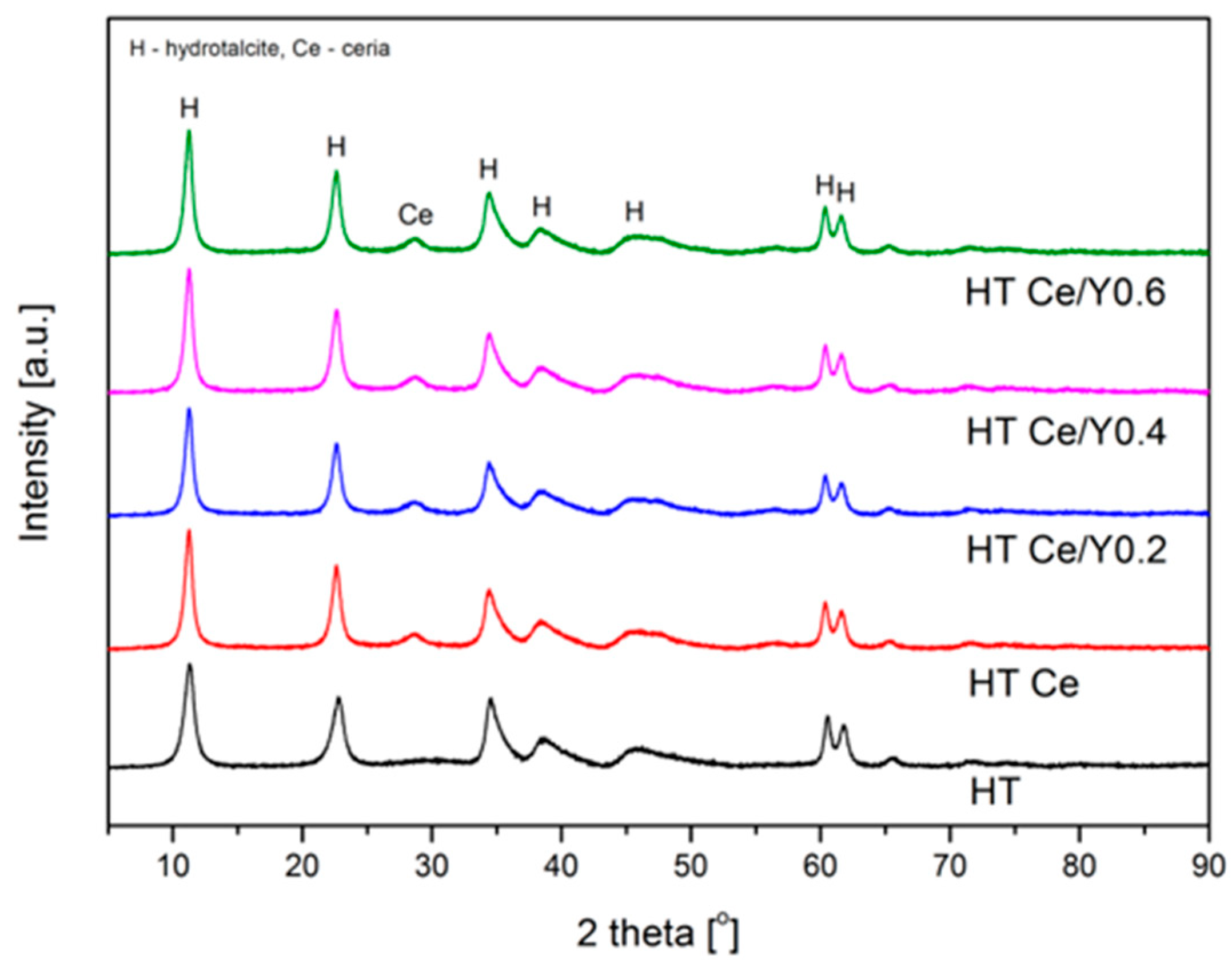
2.1. Physicochemical Features of the Studied Catalysts

XRD diffractograms of freshly synthesized double-layered hydroxides are presented in Figure 1. The XRD patterns show the sharp reflections for (003), (006), (009), (015), (110), (018), and (113) planes at 2θ ca. 11, 23, 35, 39, 46, 60, and 62° (ICOD 00-014-0191), respectively. Based on first three reflections, structural parameters a and c’ are calculated (Table 1). The former describes the cation–cation distance in the layers of hydrotalcite materials. This distance remained stable after promotion with cerium and cerium/yttrium. The c’ relates to the distance between two layers plus one brucite-like sheet, and the values suggest the presence of CO32− (7.65 Å) and NO3 (8.79 Å) ions [6,14]. Additionally, a separate phase of ceria is revealed in XRD diffractograms (Figure 1). However, an existence of Ce(OH)3 or CeCO3OH cannot be excluded. The former arises from Ce3+, which oxidizes fast to Ce4+ in H2O. Then it can form CeO2. The CeCO3OH was considered to be a precursor of cerium oxide upon precipitation in the presence of carbonates. In the study of Daza et al. [13] the CeCO3OH was recorded only for the sample with higher cerium content (Al/Ce = 1.5), however, well dispersed cerium carbonate hydroxide could be also formed in the low-loaded cerium materials (with assumed Al/Ce = 4.0, 9.0, 24.0). This cerium deposition on the surface of the brucite-like layers can originate from its bigger ionic radius (Ce3+ = 1.019 Å versus Mg3+ = 0.86 Å, Al3+ = 0.675 Å) [31]. Since a modification with yttrium occurred through dry impregnation, it is expected that Y is deposited on the surface of DLHs, but no separate phase of Y2O3 was recorded in XRD patterns, which is probably due to its small content.
Table 1 presents metal contents for the prepared catalysts as determined by XRF. The nickel content was found in the range of 20–25 wt.%, and for all Ce-containing catalysts the amount of cerium was very close to the one assumed during the synthesis step, i.e., 3 wt.%. The amount of introduced yttrium was also close to the assumed one. Ni2+/Mg2+ molar ratio showed values lower than 0.33, especially in Ce- and Y-promoted catalysts. It suggests that Mg2+ were only partially substituted by Ni2+. Al/Ce molar ratios calculated for the modified catalysts were in the range of 28–36, which is higher than those in the study of Daza et al. [13].
Textural properties are presented in Table 1. The modification with cerium led to a decrease of specific surface area due to a partial blockage of the surface. Similar observations were reported for Ni-hydrotalcites promoted with Ce[EDTA] [15], and after co-precipitation with Ce(NO3)3·6H2O [13]. Further modification with yttrium positively affected SBET resulting in an increase of this value. The pore volume and pore size remained almost unchanged.

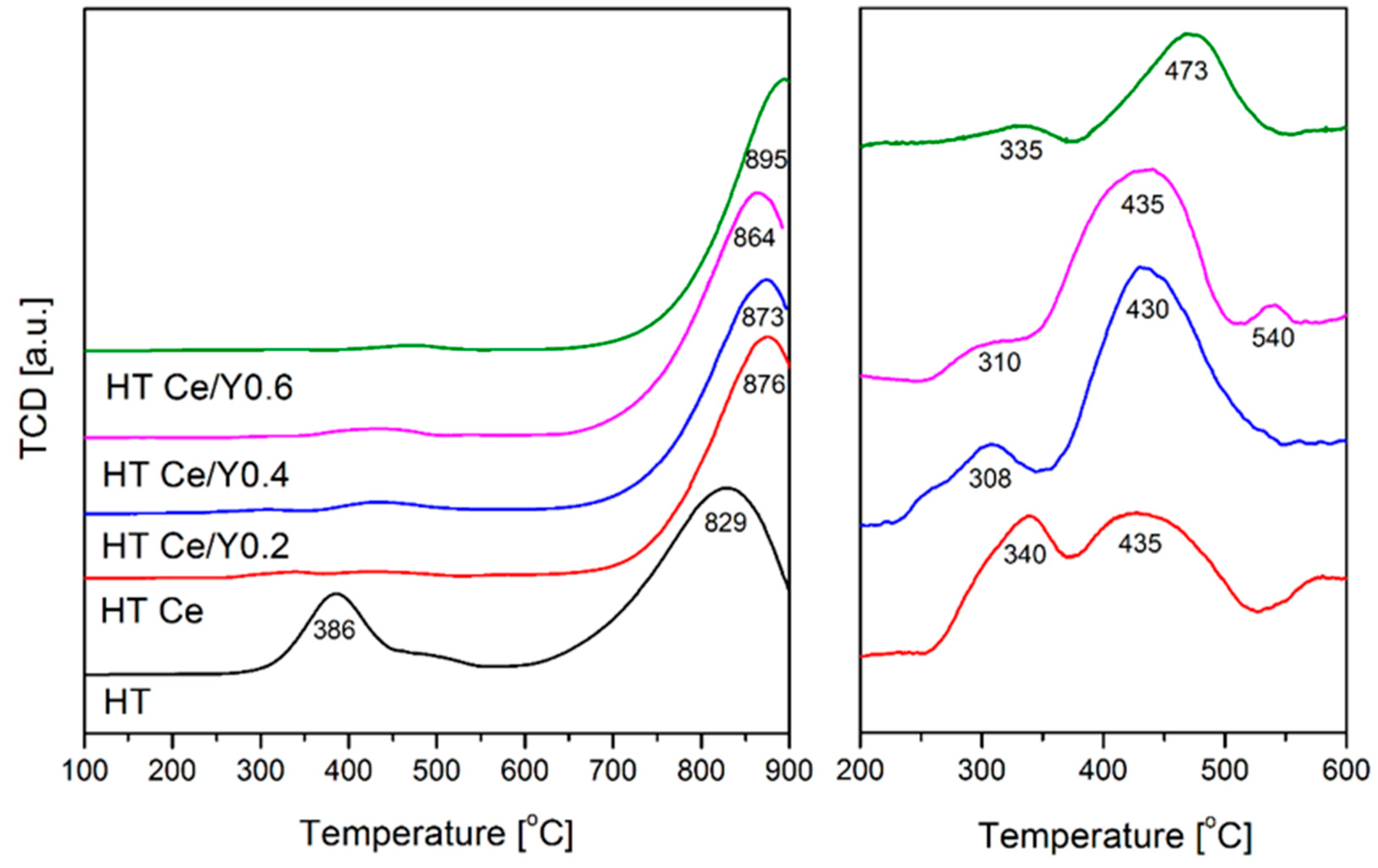
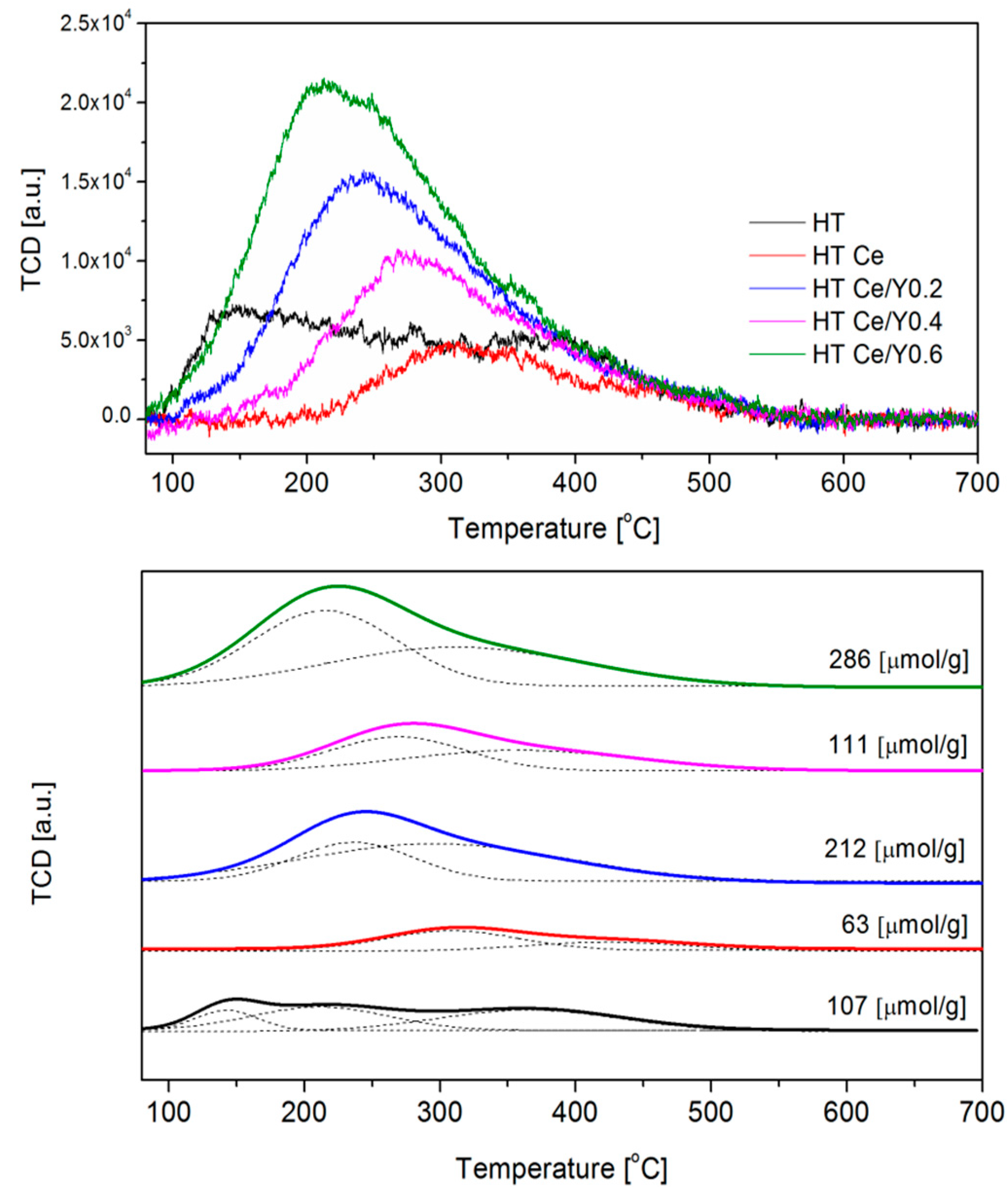
2.2. Reducibility, Basicity, Ni Dispersion, and Crystallite Size

Textural properties were examined for materials after calcination and after reduction in a mixture of 5 vol.% of H2 in Ar (Table 1 and Table 2). A significant decrease of SBET can be observed for all samples, as compared to the materials after calcination (Table 1). The highest decrease was observed for the sample modified only with ceria, similarly as reported by Han et al. [21] for NiCeAl catalyst. Moreover, a decrease in the pore volumes and pore diameters was also observed, in contrast to the values obtained for the HT sample.
TPR-H2 profiles are presented in Figure 2. One broad reflection, arising from the reduction of NiO located in the layer of DLHs, is distinguishable at ca. 860 °C. Maximum temperature of peaks shifted towards higher values after promotion with Ce (829 versus 876 °C). After addition of 0.6 wt.% of Y the temperature shift is more pronounced (873, 864, 895 °C for HT Ce/Y0.2, HT Ce/Y0.4, and HT Ce/Y0.6, respectively) (Table 2). This shows that Ce- and Y-promotions lead to a decrease in reducibility, as confirmed by the uptake of hydrogen (Table 2). Additionally, less intense peaks were recorded at moderate temperatures. At 350 °C nickel oxides, weakly-bonded with surface of hydrotalcite are reduced, as presented in the profile for the HT catalyst. Also, in reducing atmosphere ceria helps to create an oxygen reservoir through the redox behavior of Ce4+/Ce3+ [2]. Three species of ceria, with increasing reduction temperatures, were reported in literature, i.e., reduction of (i) surface oxygen at 400–420 °C, (ii) surface lattice oxygen at 450–600 °C, and (iii) total bulk reduction into Ce2O3 up to 880 °C [13]. Their presence can be observed on the right-hand side of the Figure 2, however overlapping of the peaks arising from the species assigned as (i) and (ii), makes them impossible to distinguish. Moreover, the peaks registered at temperatures lower than 400 °C, may arise from reduction of either NiO weakly interacting with the surface of the catalyst or bulk NiO [4,18,32]. Similar conclusions may be drawn for species (iii), which peaks can overlap with reduction of NiO derived from the structure.
XRD patterns for the reduced samples are presented in Figure 3. Fluorite CeO2 phase was detected (ICOD 00-023-1048), together with the periclase mixed-oxides (ICOD 00-045-0946). The latter are typically formed upon calcination [13,15]. The reduction in a mixture of H2/Ar resulted in metallic Ni (ICOD 01-087-0712) with crystallite sizes presented in Table 2. No increase of Ni0 particle size was observed after the modification with cerium and cerium/yttrium, in contrast to the study of Daza et al. [13], in which the co-precipitation with Ce led to the formation of free nickel oxides.
Table 2 shows the H2 consumption calculated for metallic nickel after TPR-H2. After the modification with Ce and Y a small increase of Ni0 dispersion is observed, from 8.9 for HT to 11.5, 10.2, 11.6, and 11.5% for HT Ce/Y0.2, HT Ce/Y0.4, HT Ce/Y0.6, respectively. The enhanced dispersion was also observed in the previous studies on Y-promoted catalysts, and connected with improved catalytic behavior, since better dispersed active sites make them more available for the reaction with CH4 in DRM [4]. The crystallite sizes calculated from H2 chemisorption, assuming spherical Ni crystallites, are in good agreement with the results obtained by XRD.
Figure 4 presents TPD-CO2 results for the catalysts after TPR-H2. One can note that ceria promotion led to a decrease in total basicity, whereas yttrium promotion (0.2 and 0.6 wt%) resulted in a significant increase of the number of basic sites. For the former, a similar effect was observed in the literature [14,15]. In the current study, the sequence of the total basicity is: 63, 107, 111, 212, 286 μmol/g for HT Ce < HT < HT Ce/Y0.4 < HT Ce/Y0.2 < HT Ce/Y0.6 catalysts, respectively.
According to literature, three types of basic sites may be distinguished for DLHs, i.e., (i) 135–142 °C, (ii) 203–218 °C and (iii) 316–367 °C, ascribed to weak Brønsted basic sites (surface hydroxyl groups), medium strong (Lewis acid–base sites), and strong basic sites (Lewis basic sites associated with oxygen anions), respectively [15,19]. The modification with Y and Ce promoters resulted in the loss of the weakest basic sites (Figure 4), in favor of the medium and strong ones. According to Dębek et al. [15] cerium favors the strong basicity. During DRM, strongly adsorbed CO2 will not react easily with CH4 (Le Chatelier’s principle) and thus, the methane will decompose, instead of reacting with carbon dioxide. When the influence of yttrium on basicity is concerned, there is no straight correlation between the rising Y concentration and the number of basic sites. The amount of weak basic sites decreased with the Y loading. Thus, it is evident that 0.2 wt.% of yttrium considerably affects the amount of the medium basic sites, while Y of 0.4 wt.% hindered CO2 adsorption.

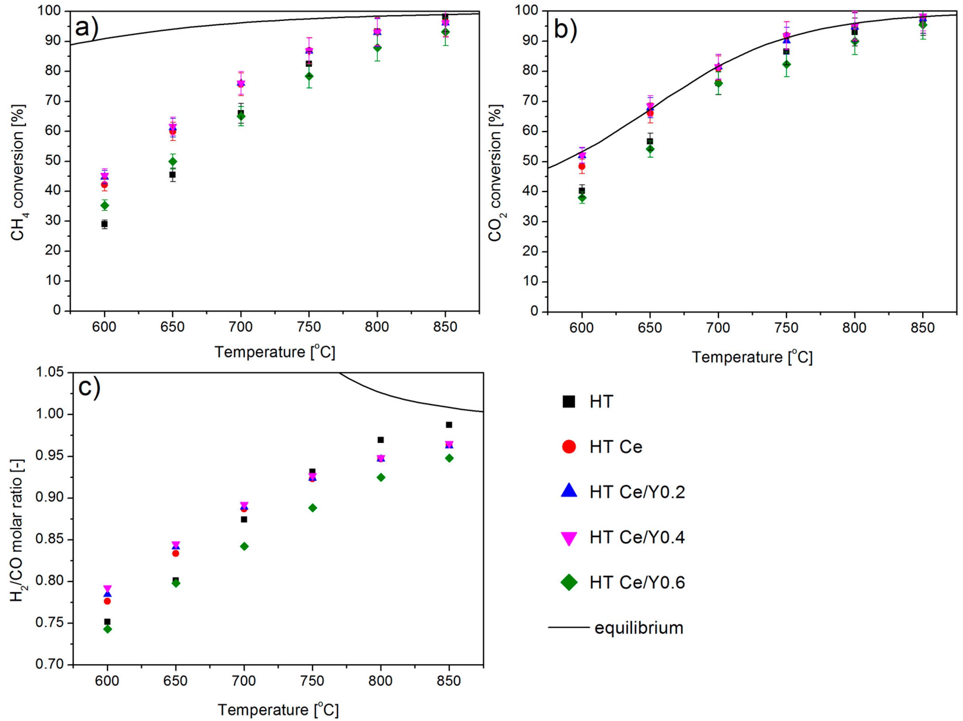
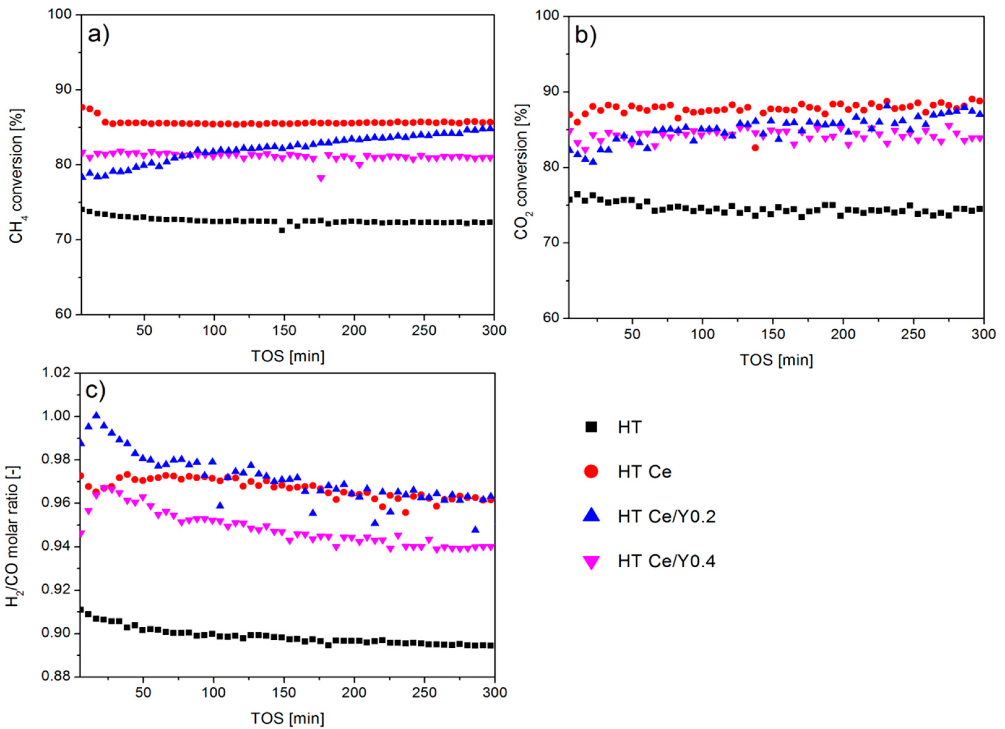
2.3. Catalytic Performance in Dry Methane Reforming

CH4 and CO2 conversions and H2/CO molar ratio in dry reforming of methane tests are presented in Figure 5 and Table 3. It may be seen that the promotion with cerium resulted in an enhanced conversion for both methane and carbon dioxide at the temperature range of 750–600 °C. Thus, the beneficial effect of Ce may be assigned to the increase of Ni0 dispersion as reported elsewhere [33,34]. In our study, the increase in the activity cannot be linked with the increased basicity, as proposed by Daza et al. [13], but likely with the Ni dispersion which is slightly higher for HT Ce, HT Ce/Y0.4 and HT Ce/Y0.6 catalysts. Both CH4 and CO2 conversions were similar for HT Ce and the catalyst promoted with Y 0.4 wt.%. However, a decrease in activity was observed for HT Ce/Y0.6 catalyst, which had the highest basicity.
In order to further examine the influence of Y promotion, isothermal tests were performed at 700 °C for 5 h for the best performing samples from the previous test: HT Ce, HT Ce/Y0.2 and HT Ce/Y0.4, and for the unmodified catalyst HT. The results are presented in Figure 6. The catalytic activity followed the sequence: HT < HT Ce/Y0.4 < HT Ce. Moreover, for HT Ce/Y0.2 catalyst, a constantly increasing conversions, for both CH4 and CO2, were observed. The lowest values of H2/CO were obtained for the unmodified catalyst (H2/CO = 0.90), whereas for both HT Ce/Y0.4 and HT Ce catalysts the values were respectively ca. 0.94 and ca. 0.97 after 300 min. Considering that the registered H2/CO molar ratio is stable from 50 min to 300 min, and the obtained values are always lower than unity, side reactions such as reverse water gas shift (CO2 + H2 = CO + H2O) may have occurred. It is to some extent, favored in the presence of Y.
It is well known that Ni0 is the active site for DRM [3], and that the DRM reaction over Ni-based catalysts proceeds through two main steps: (i) the decomposition of methane takes place on Ni active site and (ii) the dissociate adsorption of carbon dioxide on the metal surface and metal-surface interface [3,35]. During the first step of proposed mechanisms, a carbon on the Ni surface is formed as a product of CH4 decomposition (CH4 = C(s) + 2H2). This carbon atom can be then oxidized by atomic oxygen derived from CO2 in the reverse Boudouard reaction (CO2 + C = 2CO) [4]. When the excess amount of oxygen is in close proximity to the Ni0 particles, it will lead to formation of NiO, further reduced again to Ni0 due to presence of H2 in gas stream [3]. Moreover, the promoting effect of Ce has been mainly ascribed to its large oxygen storage capacity, which favors the oxidation of the carbon deposits formed upon direct methane decomposition [15,36]. The addition of Ce-species into the hydrotalcite structure was also found to promote the reducibility of the nickel species, and also resulted in the introduction of new strong basic sites (low-coordinated surface O2-) and intermediate-strength basic sites (Lewis acid/base pairings), which increased the CO2 adsorption capacity of the catalysts [15]. In our case, the Ce and Y addition does not enhance reducibility, but leads to higher Ni0 dispersion. This agrees with some studies in which Ce4+ as CeO2 was used as promotor [33,37]. All these factors have a positive effect on the catalytic activity of nickel-based catalysts in dry reforming of methane [33,34]. The authors found that addition of CeO2 into monometallic nickel effectively improves the dispersion of Ni particles on the catalyst surface and enhances the stability of the catalyst. In the presence of both, yttrium oxide and cerium oxide, it was shown that the metal–support interactions enhanced catalytic performance, due to the oxygen storage/transport characteristic of the support [38], or to the generation of active centers at the interface between metal and support [29,39,40,41]. Thus, to take advantage of the metal–support synergistic effect in the treatment of CO2 reforming of CH4, nickel in interaction with ceria-yttria appears to be appropriate for developing a catalyst that is resistant to carbon deposition and that exhibits stable operation for extended periods of time as we found in Figure 6 for both Y and Ce doped catalysts. The characterization over spent catalysts (further described in the text) has shown that Ce was always together with Y, indicating the possible presence of CeO2-Y2O3 phase, which favors Ni0 dispersion and limits the sintering and the carbon formation.

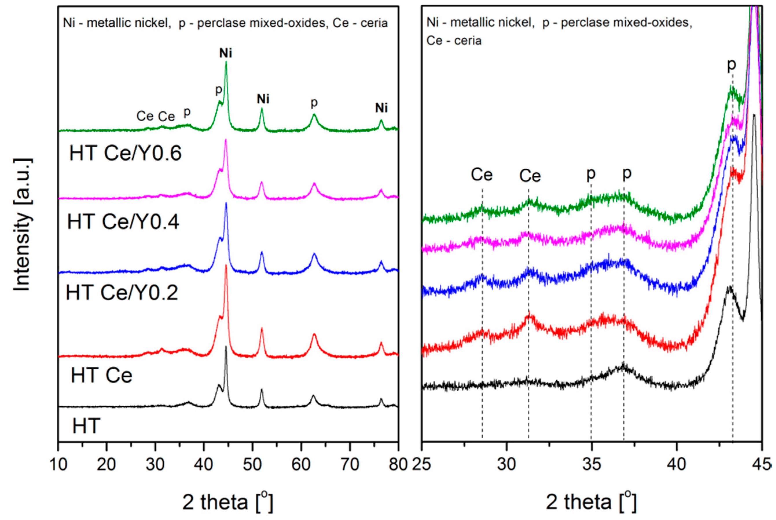
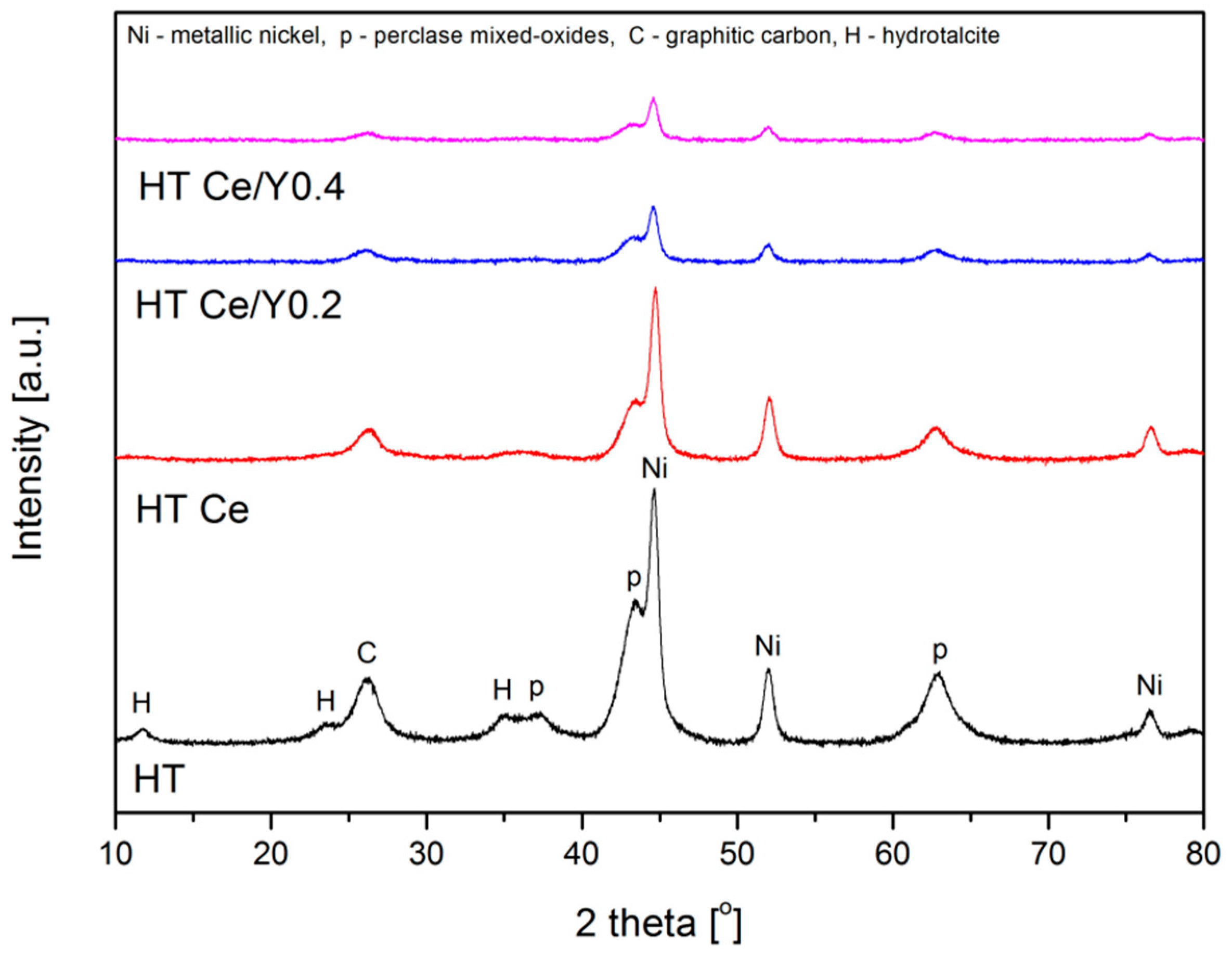
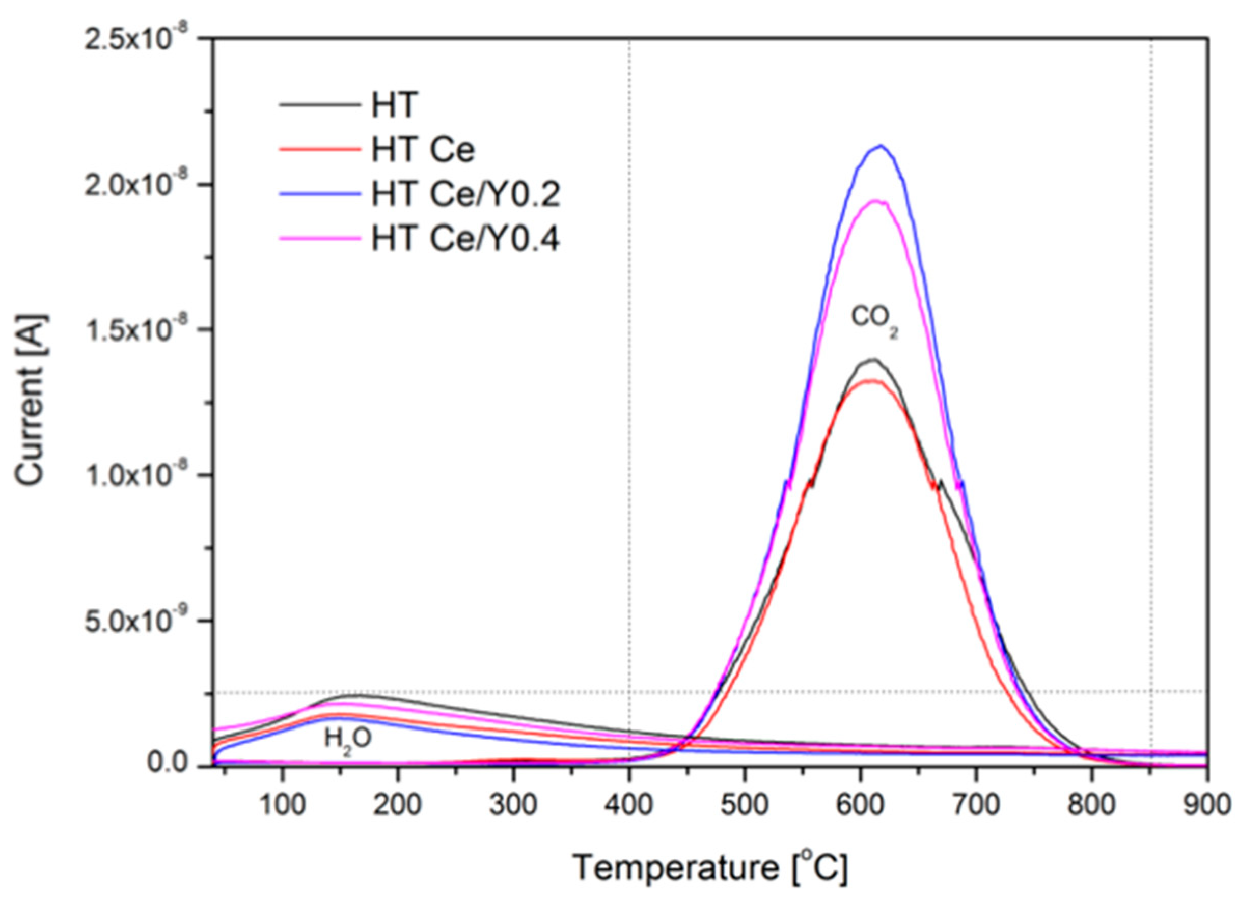
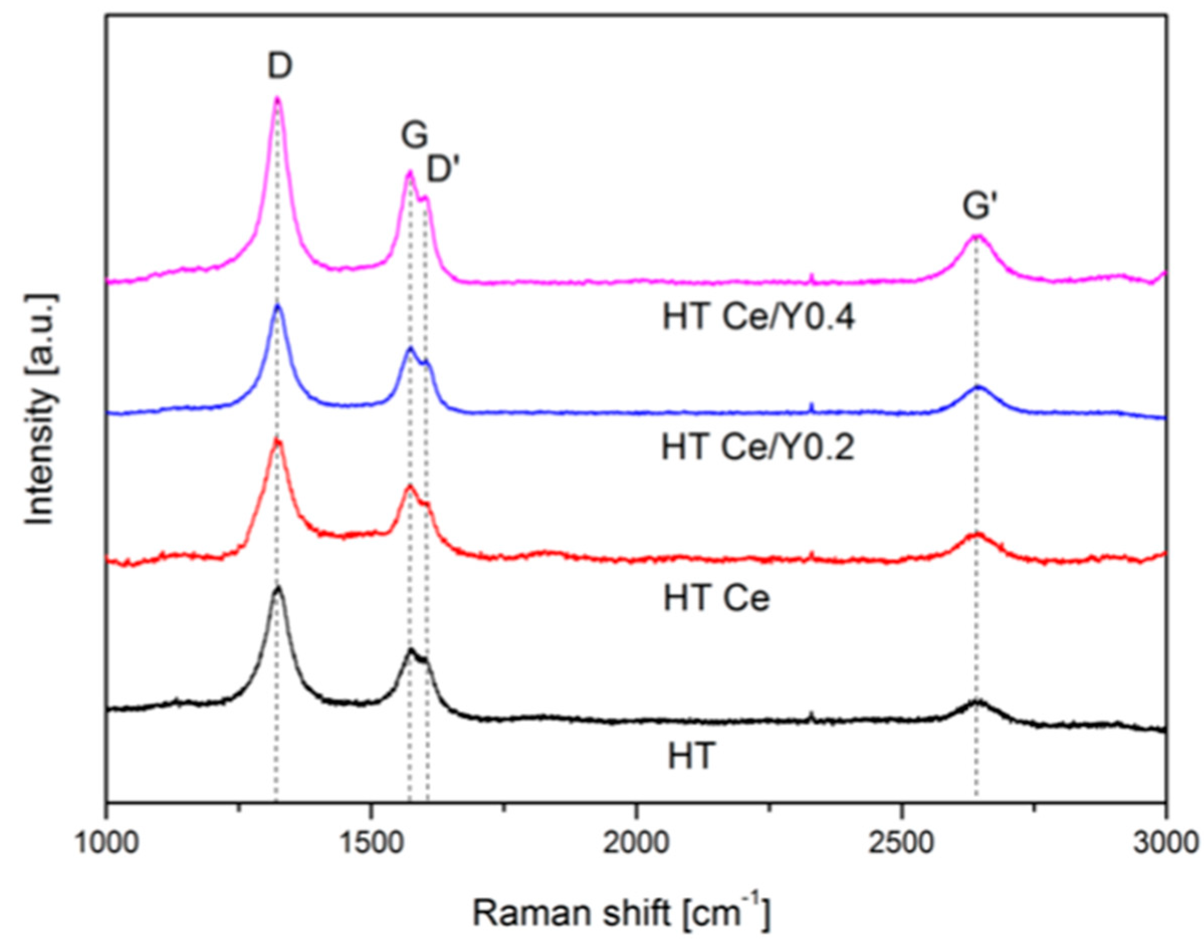
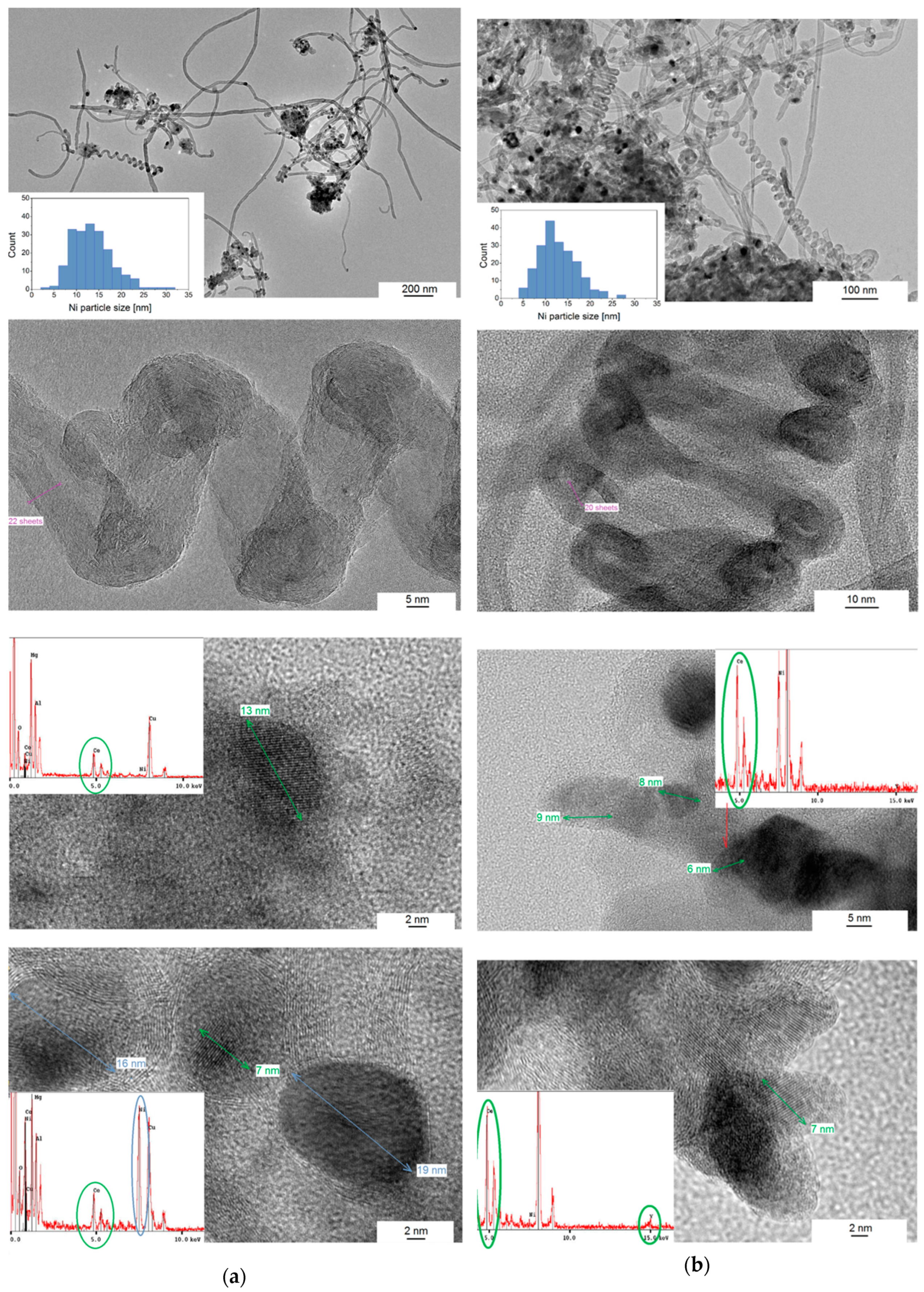
2.4. Characterization of the Spent Catalysts

Textural properties were examined for the spent catalysts after methane dry reforming tests at 700 °C for 5 h. As listed in Table 4, the specific surface area decreased after catalytic tests for the Ce-modified sample as compared to unpromoted catalyst HT (125 compared to 108 m2/g). On the contrary, addition of yttrium caused a slight increase of SBET (139 m2/g for HTNi-Y0.2). The values are close to the ones obtained for the calcined materials (Table 1).
Figure 7 presents XRD patterns of the spent catalysts after DRM tests. The Ni crystallite size, carbon formation and changes in the crystallographic structure were examined and compared to the results obtained for the reduced materials (cp. Figure 3). For the spent catalysts, typical reflections of metallic nickel (ICOD 01-087-0712) and periclase-like mixed oxides can be found (ICOD 00-045-0946). Table 4 presents the calculated values of Ni0 crystallite sizes, which did not change after the DRM tests. This proves that possible sintering of nickel was prevented after addition of ceria, confirming similar observations reported by Dębek et al. [15]. On the other hand, no spinel phase was observed in contrast to the results shown by Daza et al. [13]. It should be mentioned, however, that additional reflections of hydrotalcite with the planes of (003), (006), (009) (ICOD 00-014-0191) were registered for the HT catalyst. Their presence suggests a partial reconstruction of the support in the presence of water (product). Although CH4 and CO2 conversions were stable, the formation of carbon was observed, as confirmed by the presence of graphite reflections at 2θ = 26.6° (ICOD 01-075-2078).
The amount and the type of carbon formed on the catalysts upon the DRM were examined by TGA (Figure 8). The amount of carbon deposit was quantified from the CO2 ion current detected during its combustion (Figure 9). During the thermal decomposition of the spent materials, a small decrease of the mass is registered in the temperature range of 40–300 °C, which is connected with water vapor removal (Figure 9). An increase of the mass is observed over 300 °C, which according to Tsyganok et al. [42] arises from the oxidation of metallic nickel to nickel oxides. At 400 °C a significant decrease of the weight occurred due to the combustion of carbon deposits on the surface of the catalysts. In Figure 8, a CO2 formation is observed during the thermogravimetric analysis. For all catalysts, a peak centered at 610 °C corresponding to the carbon filaments is observed. The intensities of CO2 signals are in line with the amount of formed carbon, which were 1.97, 2.02, 2.53, 2.80 mg for HT Ce, HT, HT Ce/Y0.4, HT Ce/Y0.2, respectively.
Raman spectra after isothermal tests are presented in Figure 10. For all samples four characteristic peaks located at 1473 cm1 (D band), 1573 cm1 (G band), 1602 cm1 (D’ band), and 2644 cm1 (G’ band) can be observed. The D-band is related to the disordered structural form of crystalline carbon species, whereas G-band is associated with graphitic carbon having high order, symmetry, and crystallinity. The degree of the carbon crystallinity (ID/IG) is shown in Table 3. The highest contribution of the graphitized carbon was observed for HT Ce catalyst, giving the lowest ID/IG ratio, i.e., 1.47. For the HT Ce/Y0.2 catalyst less graphitic carbon was observed than for HT Ce, despite the higher mass loss in the TGA analysis (cp. Figure 8). Thus, although the low loadings of yttrium (0.2 wt.%) led to the creation of higher amount of carbon, such deposits had lower graphitization degree.
To gain more information on the structure of carbon deposits, high-resolution transmission electron microscopy analyzes were carried out for the samples after dry reforming of methane tests at 700 °C for 5 h. The micrographs of the spent HT Ce and HT Ce/Y0.4 catalysts are presented in Figure 11a,b. Helix-shaped carbon nanotubes are observed together with the high number of straight tubes, with well-defined graphite sheets with d-spacing of 3.3 Å for (111) planes. The helix-shaped nanotubes can be formed due to periodic incorporation of pentagon-heptagon pairs into a hexagonal carbon framework, generating curved surfaces [43]. Figure 11a additionally shows a high-resolution detail of tightly wound helix-shaped carbon nanotube containing 20–22 graphene sheets. Also, well-dispersed cylindrical nickel particles of the mean size of 11–12 nm were registered. However, most of them were encapsulated with the carbon layers of dhkl = 3.35 Å (Figure 11). In HT Ce catalyst, cerium oxide particles were detected with distance of 3.2 Å (111) and the particle size of 7–13 nm. Some CeO2 particles formed aggregates in close vicinity to Ni. In case of the Y-modified sample, the particles of cerium oxide were single or together with small particles of yttrium (Figure 11b). Based on the recorded distance of 3.05 Å, it is hard to distinguish if a solid solution of CeO2-Y2O3 has been formed (dhkl = 3.12 Å for cubic) or two particles of cerium oxide and yttrium oxide are just neighboring each other (dhkl = 3.12 Å for cubic CeO2, dhkl = 3.06 Å for cubic Y2O3). This possible phase of yttria-doped ceria (YDC) can explain the high catalytic activity and better Ni0 dispersion in agreement with literature [29].
Moreover, the support has been crystalized again in both samples, as confirmed by presence of the Mg and Al signals in EDS, and distance of dhkl = 2.52 Å probably arising from (009) plane. This is in the good agreement with the textural properties obtained for spent samples, i.e., value of SBET close to the one obtained for the calcined material.

3. Materials and Methods

3.1. Catalysts Synthesis

Double layered hydroxides, containing divalent M(II) and trivalent (III) ions (Ni2+, Mg2+, Al3+ and/or Ce3+) were synthesized with assumed M(III)/M(II) molar ratio of 0.33. 3 wt.% was presumed in the Ce-containing samples. Co-precipitation method at constant pH = 9.8–10.2 was carried out with two aqueous solutions containing metal nitrates and sodium hydroxide (2 M) in the presence of sodium carbonate. The mixture was vigorous stirred at 65 °C. Afterwards, the solution was left to react for next 24 h at 65 °C, filtered and washed with deionized water. The solid cake was dried at 80 °C overnight. The freshly synthesized material was then divided into four portions and three of them were impregnated with yttrium nitrate, assuming Y content of 0.2, 0.4, or 0.6 wt.%. Finally, the dried materials were calcined at 550 °C for 5 h, and labelled as HT, HT Ce, HT Ce/Y0.2, HT Ce/Y0.4, and HT Ce/Y0.6.

3.2. Characterization Methods

Elemental analysis was carried out by Wavelength Dispersive X-Ray Fluorescence (WDXRF) using a Supermini200 instrument (Rigaku, Neu-Isenburg, Germany). Fifty milligrams of calcined materials were diluted in 2 g of boric acid and pelletized under a press (10 bar) for 15 min. The pellets were deposited in sample holders, and covered with 6 µm polypropylene film. The analyzes were carried out under vacuum at 36.5 °C in the presence of P-10 gas (a mixture of 10% CH4 in Ar with 24.7 cm3/min of flow). The quantities of metals were calculated by ZSX software (Rigaku, Neu-Isenburg, Germany).
Nitrogen sorption via a Micromeritics TriStar II 3020 (Micromeritics, Aachen, Germany) was used in order to verify the textural properties. The materials were degassed for 3 h at 110 °C before their subsequent measurements.
X-ray diffraction (XRD) patterns were obtained from PANalytical-Empyrean diffractometer (Malvern Panalytical B.V., Almelo, The Netherlands), equipped with CuKα (λ = 0.15406 nm) radiation source. From XRD, the medium crystallite size of nickel crystallite size was calculated based on the Scherrer equation.
In order to measure the reducibility of the Ni based double-layered hydroxides, temperature-programmed reduction (TPR-H2) experiments were carried out on a BELCAT-M (BEL Japan, Inc., Osaka, Japan) equipped with a thermal conductivity detector (TCD). Sixty milligrams of calcined were first degassed in helium atmosphere at 100 °C for 2 h and then reduced in 5% H2/Ar mixture with a heating rate of 10 °C/min starting from 100 °C to 900 °C. Temperature-programmed desorption (TPD-CO2) was performed after TPR-H2 run, using the same device. CO2 was adsorbed at 80 °C for 1 h from a mixture of 10% CO2/He. Then, helium flow was applied for 15 min in order to desorb weakly adsorbed CO2. Finally, the materials were heated from 80 °C to 800 °C in helium in order to determine the basic properties of the materials based on temperature of desorption. TPD profiles were deconvoluted into three Gaussian peaks corresponding to weak, medium and strong basic sites in agreement with literature [15,19].
Hydrogen chemisorption was used to determine nickel dispersion using a Micromeritics, ASAP 2020S (Micromeritics, Aachen, Germany). Thus, 200 mg of calcined materials were loaded in tubular quartz reactor. Prior the experiments, evacuation at 40 °C for 1 h and reduction in pure H2 at 900 °C for 1 h was applied. After the reduction, the sample was evacuated in helium for 30 min at 900 °C and subsequently for 1 h at 40 °C. Then the leak test was performed. Prior to H2 chemisorption, the sample was evacuated for 30 min at 40 °C in helium. The metal dispersion was determined based on the quantity of hydrogen uptake. Moreover, from chemisorption technique, the crystallite size was also calculated, considering spherical metal crystallites with a uniform size [44].
Thermogravimetric analyzes were carried out by a TGA-MS (TGA: Netzsch STA 449C Jupiter, MS: Netzsch Aërlos QMS 403C, Netzsh Group, Selb, Germany) in order to examine the deposited coke on spent catalysts. A mixture of air (flow of 100 cm3/min) and protective gas (flow of 20 cm3/min) was applied. Ten milligrams of a spent sample was heated starting from room temperature to 900 °C with a heating rate of 10 °C/min. The amount of formed carbon was estimated by the mass loss in TGA analysis, confirming by CO2 production derived from MS results.
Raman measurements were performed by using a Horiba Jobin Yvon LabRam HR800 spectrophotometer (HORIBA, Kyoto, Japan) to characterize carbon deposition on the spent catalysts after DRM. The spectra were recorded in range of 3000–1000 cm−1 at room temperature. The excitation source was 633 nm of Ne-Ne laser. The spectra were recorded with an accumulation of 3 and an acquisition time of 20 s. A diffraction grating of 1800 g/mm and a 50× objective were applied.
High-Resolution Transmission Electron Microscopy (JEOL JEM-2010, Croissy-sur -Seine, France with EDS) was used to characterize the deposited carbon and to obtain precise analysis of the planes registered at the nanometer scale. The specimens were prepared by dropwise addition of a colloidal solution in ethanol onto a copper grid covered with amorphous carbon film.

3.3. Catalytic Tests

The DRM tests for Ce- and Y-promoted catalysts were carried out in the fixed-bed quartz reactor heated inside an electric furnace. In each experiment 100–150 mg of calcined material was tested, depending on sample’s density. The temperature of the catalyst bed was controlled with the aid of a K-type thermocouple. The total flow of feed gases was 100 cm3/min, corresponding to the GHSV of 20,000 h1. The products of the reaction were analyzed by an on-line Varian GC490 micro chromatograph equipped with a TCD detector. Prior to each catalytic test, a catalyst was reduced in situ with a mixture of 5% H2 in Ar for 1 h at 900 °C. Two types of tests were performed: (i) at the temperature range of 850–600 °C, (ii) isothermal test at 700 °C for 5 h.

4. Conclusions

The dry reforming of methane was studied over the double-layered hydroxides modified with cerium (co-precipitation method) and with yttrium (the incipient wetness impregnation method with 0.2, 0.4 and 0.6 wt.%). The promotion with both Ce and Y led to the decrease of reducibility of Ni, an increase of the basicity, enhanced Ni dispersion and smaller Ni crystallite size as compared to the HT catalyst. This can be explained by a possible formation of yttria-doped ceria (YDC) phase. Modification with the smallest loading of yttrium (0.2 wt.%) led to the increase of both CO2 and CH4 conversions during isothermal DRM tests for 5 hours. This enhancement of the activity is caused by side reactions. No clear deactivation was reported during the isothermal tests; however, formation of carbon was evident as spent samples were analyzed by TGA/MS, Raman and HRTEM. The amount of coke was higher for Y-promoted samples, although it was less graphitic as compared to the HT Ce catalyst.

Author Contributions

Formal analysis, K.Ś., M.R., P.B., P.D.C. and T.G.; Investigation, K.Ś.; Methodology, K.Ś., P.B., M.M. and T.G.; Resources, M.R., M.M., P.D.C. and T.G.; Supervision, M.R., M.M., P.D.C. and T.G.; Validation, M.M. and T.G.; Visualization, M.R.; Writing—original draft, K.Ś., P.D.C. and T.G.

Funding

K.Ś. acknowledges the French Embassy in Poland for her grant “BGF Doctorat en cotutelle” between Sorbonne University and AGH University of Science and Technology. InnoEnergy PhD school is acknowledged for the financial support. K.Ś. would also like to express her gratitude to the KinCat Catalysis Group at NTNU for the possibility to conduct her research during an Erasmus+ traineeship. T.G. and M.M. thank AGH grant 11.11.210.373.

Conflicts of Interest

The authors declare no conflict of interest.

References

  1. Mark, M.F.; Maier, W.F.; Mark, F. Reaction kinetics of the CO2 reforming of methane. Chem. Eng. Technol. 1997, 20, 361–370. [Google Scholar] [CrossRef]
  2. Pakhare, D.; Spivey, J. A review of dry (CO2) reforming of methane over noble metal catalysts. Chem. Soc. Rev. 2014, 43, 7813–7837. [Google Scholar] [CrossRef] [PubMed]
  3. Seo, H. Recent scientific progress on developing supported Ni catalysts for dry (CO2) reforming of methane. Catalysts 2018, 8, 110. [Google Scholar] [CrossRef]
  4. Świrk, K.; Gálvez, M.E.; Motak, M.; Grzybek, T.; Rønning, M.; Da Costa, P. Yttrium promoted Ni-based double-layered hydroxides for dry methane reforming. J. CO2 Util. 2018, 27, 247–258. [Google Scholar] [CrossRef]
  5. Chen, D.; Lødeng, R.; Anundskås, A.; Olsvik, O.; Holmen, A. Deactivation during carbon dioxide reforming of methane over Ni catalyst: Microkinetic analysis. Chem. Eng. Sci. 2001, 56, 1371–1379. [Google Scholar] [CrossRef]
  6. Cavani, F.; Trifirò, F.; Vaccari, A. Hydrotalcite-type anionic clays: Preparation, properties and applications. Catal. Today 1991, 11, 173–301. [Google Scholar] [CrossRef]
  7. Dębek, R.; Motak, M.; Grzybek, T.; Galvez, M.; Da Costa, P. A short review on the catalytic activity of hydrotalcite-derived materials for dry reforming of methane. Catalysts 2017, 7, 32. [Google Scholar] [CrossRef]
  8. González, A.R.; Asencios, Y.J.O.; Assaf, E.M.; Assaf, J.M. Dry reforming of methane on Ni-Mg-Al nano-spheroid oxide catalysts prepared by the sol-gel method from hydrotalcite-like precursors. Appl. Surf. Sci. 2013, 280, 876–887. [Google Scholar] [CrossRef]
  9. Lin, X.; Li, R.; Lu, M.; Chen, C.; Li, D.; Zhan, Y.; Jiang, L. Carbon dioxide reforming of methane over Ni catalysts prepared from Ni-Mg-Al layered double hydroxides: Influence of Ni loadings. Fuel 2015, 162, 271–280. [Google Scholar] [CrossRef]
  10. Touahra, F.; Sehailia, M.; Ketir, W.; Bachari, K.; Chebout, R.; Trari, M.; Cherifi, O.; Halliche, D. Effect of the Ni/Al ratio of hydrotalcite-type catalysts on their performance in the methane dry reforming process. Appl. Petrochem. Res. 2016, 6, 1–13. [Google Scholar] [CrossRef]
  11. Dębek, R.; Motak, M.; Duraczyska, D.; Launay, F.; Galvez, M.E.; Grzybek, T.; Da Costa, P. Methane dry reforming over hydrotalcite-derived Ni–Mg–Al mixed oxides: The influence of Ni content on catalytic activity, selectivity and stability. Catal. Sci. Technol. 2016, 6, 6705–6715. [Google Scholar] [CrossRef]
  12. Daza, C.E.; Cabrera, C.R.; Moreno, S.; Molina, R. Syngas production from CO2 reforming of methane using Ce-doped Ni-catalysts obtained from hydrotalcites by reconstruction method. Appl. Catal. A Gen. 2010, 378, 125–133. [Google Scholar] [CrossRef]
  13. Daza, C.E.; Moreno, S.; Molina, R. Co-precipitated Ni-Mg-Al catalysts containing Ce for CO2 reforming of methane. Int. J. Hydrog. Energy 2011, 36, 3886–3894. [Google Scholar] [CrossRef]
  14. Dębek, R.; Motak, M.; Galvez, M.E.; Da Costa, P.; Grzybek, T. Catalytic activity of hydrotalcite-derived catalysts in the dry reforming of methane: On the effect of Ce promotion and feed gas composition. React. Kinet. Mech. Catal. 2017, 121, 185–208. [Google Scholar] [CrossRef]
  15. Dębek, R.; Radlik, M.; Motak, M.; Galvez, M.E.; Turek, W.; Da Costa, P.; Grzybek, T. Ni-containing Ce-promoted hydrotalcite derived materials as catalysts for methane reforming with carbon dioxide at low temperature—On the effect of basicity. Catal. Today 2015, 257, 59–65. [Google Scholar] [CrossRef]
  16. Niu, J.; Liland, S.E.; Yang, J.; Rout, K.R.; Ran, J.; Chen, D. Effect of oxide additives on the hydrotalcite derived Ni catalysts for CO2 reforming of methane. Chem. Eng. J. 2018. [Google Scholar] [CrossRef]
  17. Dębek, R.; Motak, M.; Galvez, M.E.; Grzybek, T.; Da Costa, P. Promotion effect of zirconia on Mg(Ni,Al)O mixed oxides derived from hydrotalcites in CO2 methane reforming. Appl. Catal. B Environ. 2018, 36–46. [Google Scholar] [CrossRef]
  18. Świrk, K.; Gálvez, M.E.; Motak, M.; Grzybek, T.; Rønning, M.; Da Costa, P. Dry reforming of methane over Zr- and Y-modified Ni/Mg/Al double-layered hydroxides. Catal. Commun. 2018, 117, 26–32. [Google Scholar] [CrossRef]
  19. Liu, H.; Wierzbicki, D.; Debek, R.; Motak, M.; Grzybek, T.; Da Costa, P.; Gálvez, M.E. La-promoted Ni-hydrotalcite-derived catalysts for dry reforming of methane at low temperatures. Fuel 2016, 182, 8–16. [Google Scholar] [CrossRef]
  20. Ainirazali, N.; Ainun, N.; Abghazab, N.; Setiabudi, H.D.; Yee, C.S. CO2 reforming of methane over Ni/Ce-SBA-15: Effects of Ce addition. Indian J. Sci. Technol. 2017, 10, 1–5. [Google Scholar] [CrossRef]
  21. Han, J.; Zhan, Y.; Street, J.; To, F.; Yu, F. Natural gas reforming of carbon dioxide for syngas over Ni–Ce–Al catalysts. Int. J. Hydrog. Energy 2017, 42, 18364–18374. [Google Scholar] [CrossRef]
  22. Koo, K.Y.; Roh, H.S.; Jung, U.H.; Yoon, W.L. CeO2 promoted Ni/Al2O3 catalyst in combined steam and carbon dioxide reforming of methane for gas to liquid (GTL) process. Catal. Lett. 2009, 130, 217–221. [Google Scholar] [CrossRef]
  23. Świrk, K.; Gálvez, M.E.; Motak, M.; Grzybek, T.; Rønning, M.; Da Costa, P. Syngas production from dry methane reforming over yttrium-promoted nickel-KIT-6 catalysts. Int. J. Hydrog. Energy 2019, 44, 274–286. [Google Scholar] [CrossRef]
  24. Huang, X.; Xue, G.; Wang, C.; Zhao, N.; Sun, N.; Wei, W.; Sun, Y. Highly stable mesoporous NiO–Y2O3–Al2O3 catalysts for CO2 reforming of methane: Effect of Ni embedding and Y2O3 promotion. Catal. Sci. Technol. 2016, 6, 449–459. [Google Scholar] [CrossRef]
  25. Li, B.; Zhang, S. Methane reforming with CO2 using nickel catalysts supported on yttria-doped SBA-15 mesoporous materials via sol-gel process. Int. J. Hydrog. Energy 2013, 38, 14250–14260. [Google Scholar] [CrossRef]
  26. Li, B.; Su, W.; Wang, X.; Wang, X. Alumina supported Ni and Co catalysts modified by Y2O3 via different impregnation strategies: Comparative analysis on structural properties and catalytic performance in methane reforming with CO2. Int. J. Hydrog. Energy 2016, 41, 14732–14746. [Google Scholar] [CrossRef]
  27. Munteanu, G.; Petrova, P.; Ivanov, I.; Liotta, L.F.; Kaszkur, Z.; Tabakova, T.; Ilieva, L. Temperature-programmed reduction of lightly yttrium-doped Au/CeO2 catalysts: Correlation between oxygen mobility and WGS activity. J. Therm. Anal. Calorim. 2018, 131, 145–154. [Google Scholar] [CrossRef]
  28. Burbano, M.; Norberg, S.T.; Hull, S.; Eriksson, S.G.; Marrocchelli, D.; Madden, P.A.; Watson, G.W. Oxygen vacancy ordering and the conductivity maximum in Y2O3-doped CeO2. Chem. Mater. 2012, 24, 222–229. [Google Scholar] [CrossRef]
  29. Wang, J.B.; Tai, Y.L.; Dow, W.P.; Huang, T.J. Study of ceria-supported nickel catalyst and effect of yttria doping on carbon dioxide reforming of methane. Appl. Catal. A Gen. 2001, 218, 69–79. [Google Scholar] [CrossRef]
  30. Guo, Y.; Zou, J.; Shi, X.; Rukundo, P.; Wang, Z.J. A Ni/CeO2-CDC-SiC catalyst with improved coke resistance in CO2 reforming of methane. ACS Sustain. Chem. Eng. 2017, 5, 2330–2338. [Google Scholar] [CrossRef]
  31. Fernández, J.M.; Barriga, C.; Ulibarri, M.A.; Labajos, F.M.; Rives, V. New hydrotalcite-like compounds containing yttrium. Chem. Mater. 1997, 9, 312–318. [Google Scholar] [CrossRef]
  32. Dębek, R.; Motak, M.; Galvez, M.E.; Grzybek, T.; Da Costa, P. Influence of Ce/Zr molar ratio on catalytic performance of hydrotalcite-derived catalysts at low temperature CO2 methane reforming. Int. J. Hydrog. Energy 2017, 42, 1–12. [Google Scholar] [CrossRef]
  33. Rad, S.J.H.; Haghighi, M.; Eslami, A.A.; Rahmani, F.; Rahemi, N. Sol-gel vs. impregnation preparation of MgO and CeO2 doped Ni/Al2O3 nanocatalysts used in dry reforming of methane: Effect of process conditions, synthesis method and support composition. Int. J. Hydrog. Energy 2016, 41, 5335–5350. [Google Scholar] [CrossRef]
  34. Mierczynski, P.; Mierczynska, A.; Ciesielski, R.; Mosinska, M.; Nowosielska, M.; Czylkowska, A.; Maniukiewicz, W.; Szynkowska, M.; Vasilev, K. High active and selective Ni/CeO2–Al2O3 and Pd–Ni/CeO2–Al2O3 catalysts for oxy-steam reforming of methanol. Catalysts 2018, 8, 380. [Google Scholar] [CrossRef]
  35. Aramouni, N.A.K.; Touma, J.G.; Tarboush, B.A.; Zeaiter, J.; Ahmad, M.N. Catalyst design for dry reforming of methane: Analysis review. Renew. Sustain. Energy Rev. 2018, 82, 2570–2585. [Google Scholar] [CrossRef]
  36. Koubaissy, B.; Pietraszek, A.; Roger, A.C.; Kiennemann, A. CO2 reforming of methane over Ce-Zr-Ni-Me mixed catalysts. Catal. Today 2010, 157, 436–439. [Google Scholar] [CrossRef]
  37. Li, H.; Xu, H.; Wang, J. Methane reforming with CO2 to syngas over CeO2-promoted Ni/Al2O3-ZrO2 catalysts prepared via a direct sol-gel process. J. Nat. Gas Chem. 2011, 20, 1–8. [Google Scholar] [CrossRef]
  38. Metcalfe, I.S.; Sundaresan, S. Oxygen transfer between metals and oxygen-ion conducting supports. AIChE J. 1988, 34, 195–208. [Google Scholar] [CrossRef]
  39. Wang, J.B.; Shih, W.H.; Huang, T.J. Study of Sm2O3-doped CeO2/Al2O3-supported copper catalyst for CO oxidation. Appl. Catal. A Gen. 2000, 203, 191–199. [Google Scholar] [CrossRef]
  40. Silver, R.G.; Hou, C.J.; Ekerdt, J.G. The role of lattice anion vacancies in the activation of CO and as the catalytic site for methanol synthesis over zirconium dioxide and yttria-doped zirconium dioxide. J. Catal. 1989, 118, 400–416. [Google Scholar] [CrossRef]
  41. Dilara, P.A.; Vohs, J.M. TPD and HREELS investigation of the reaction of formic acid on ZrO2(100). J. Phys. Chem. 1993, 97, 12919–12923. [Google Scholar] [CrossRef]
  42. Tsyganok, A.I.; Tsunoda, T.; Hamakawa, S.; Suzuki, K.; Takehira, K.; Hayakawa, T. Dry reforming of methane over catalysts derived from nickel-containing Mg-Al layered double hydroxides. J. Catal. 2003, 213, 191–203. [Google Scholar] [CrossRef]
  43. Amelinckx, S.; Zhang, X.B.; Bernaerts, D.; Zhang, X.F.; Ivanov, V.; Nagy, J.B. A formation mechanism for catalytically grown helix-shaped graphite nanotubes. Science 1994, 265, 635–639. [Google Scholar] [CrossRef] [PubMed]
  44. Mustard, D.G.; Bartholomew, C.H. Determination of metal crystallite supported size and morphology supported nickel catalysts. J. Catal. 1981, 67, 186–206. [Google Scholar] [CrossRef]
Figure 1. XRD patterns of freshly synthesized double-layered hydroxides (HT) catalysts: HT, HT Ce, HT Ce/Y0.2, HT Ce/Y0.4, HT Ce/Y0.6.
Catalysts 09 00056 g001
Figure 2. Temperature-programmed reduction (TPR-H2) profiles recorded for Ce- and Y-modified catalysts. H2 consumption was recorded with the aid of a thermal conductivity detector (TCD).
Catalysts 09 00056 g002
Figure 3. XRD diffractograms of the prepared catalysts after reduction in the mixture 5 vol.% of H2/Ar.
Catalysts 09 00056 g003
Figure 4. TPD-CO2 plots for Ce- and Y-modified catalysts.
Catalysts 09 00056 g004
Figure 5. The results of DRM catalytic tests over Ce- and Y-modified catalysts: (a) CH4 conversion, (b) CO2 conversion and (c) H2/CO molar ratio. Reaction conditions: T = 850–600 °C, 30 min at each temperature, GHSV = 20,000 h−1, CH4/CO2/Ar = 1/1/8, total flow rate 100 cm3/min.
Catalysts 09 00056 g005
Figure 6. The results of DRM catalytic tests over Ce- and Y-modified catalysts: (a) CH4 conversion, (b) CO2 conversion and (c) H2/CO molar ratio. Reaction conditions: T = 700 °C, 5 h, GHSV = 20,000 h−1, CH4/CO2/Ar = 1/1/8, total flow rate 100 cm3/min.
Catalysts 09 00056 g006
Figure 7. XRD diffractograms recorded for the spent catalysts after isothermal tests at 700 °C for 5 h.
Catalysts 09 00056 g007
Figure 8. Thermogravimetric analysis (TGA) for the catalysts after isothermal DRM tests.
Catalysts 09 00056 g008
Figure 9. Mass spectrometry (MS) signals of water vapor and carbon dioxide during thermal decomposition of the spent catalysts.
Catalysts 09 00056 g009
Figure 10. Raman spectra recorded for the spent catalysts.
Catalysts 09 00056 g010
Figure 11. HRTEM micrographs of (a) HT Ce; and (b) HT Ce/Y0.4 catalysts after dry reforming of methane test at 700 °C for 5 h.
Catalysts 09 00056 g011
Table 1. Structural parameters, elemental composition, and textural properties.
CatalystXRD XRFN2 Sorption
Freshly Synthesized After Calcination After Calcination
a 1 [Å]c’ 2 [Å]Ni [wt.%] Ce [wt.%] Y [wt.%] Al/Ce [-]Ni2+/Mg2+ [-]SBET 3 [m2/g] Vp 4 [cm3/g]dp 5 [nm]
HT3.067.8220---0.29 (0.33)1200.619
HT Ce3.077.84252.5 (3.0) *-340.21 (0.33)970.520
HT Ce/Y0.23.077.83232.9 (3.0) *0.3 (0.2) *300.18 (0.33)1320.721
HT Ce/Y0.43.077.84233.2 (3.0) *0.5 (0.4) *280.18 (0.33)1330.619
HT Ce/Y0.63.077.85202.6 (3.0) *0.7 (0.6) *360.15 (0.33)1260.620
1 calculated from d-spacing a = 2d(110) as suggested by Cavani et al. [6]. 2 c’ = c/3, where (c = d(003) + 2d(006) + 3d(009)) [14]. 3 specific surface area calculated from the Brunauer-Emmett-Teller (BET) calculation method. 4 pore volumes derived from the Barrett, Joyner and Halenda (BJH) desorption method. 5 pore size distribution obtained from the Barrett, Joyner and Halenda (BJH) desorption method.
Table 2. Texture, reducibility and Ni dispersion and Ni crystallite sizes for the studied materials after reduction in a mixture of 5 vol.% H2/Ar.
CatalystN2 SorptionTPR-H2XRDH2 Chemisorption
Reduced MaterialsH2 Consumption [mmol H2/g]Ni Crystallite [nm]Ni Dispersion [%]Ni Crystallite [nm]
SBET 1 [m2/g]Vp 2 [cm3/g]dp 3 [nm]
HT680.4210.20998.911
HT Ce450.2140.137711.58
HT Ce/Y0.2990.7280.135710.210
HT Ce/Y0.4910.6270.134711.68
HT Ce/Y0.6990.7260.119811.58
1 specific surface area calculated from the Brunauer-Emmett-Teller (BET) calculation method. 2 pore volumes derived from the Barrett, Joyner and Halenda (BJH) desorption method. 3 pore size distribution obtained from the Barrett, Joyner and Halenda (BJH) desorption method.
Table 3. DRM catalytic results over Ce and Ce,Y modified catalysts at different temperatures (from 850 to 600 °C, GHSV = 20,000 h−1, CH4/CO2/Ar = 1/1/8, total flow rate 100 cm3/min).
Temperature [°C]850 800 750 700 650 600
CH4 conversion
HT98.293.382.566.045.428.9
HT Ce96.593.286.975.760.042.2
HT Ce/Y0.296.292.986.876.161.244.7
HT Ce/Y0.496.293.186.876.161.745.2
HT Ce/Y0.693.287.978.465.049.935.3
CO2 conversion
HT96.893.086.576.056.640.2
HT Ce97.594.891.981.066.148.4
HT Ce/Y0.297.494.790.181.467.952.0
HT Ce/Y0.498.495.191.881.568.452.2
HT Ce/Y0.695.490.182.376.154.238.0
H2/CO molar ratio
HT0.990.970.930.870.800.75
HT Ce0.960.940.920.890.830.78
HT Ce/Y0.20.960.950.920.890.840.78
HT Ce/Y0.40.970.950.930.890.850.79
HT Ce/Y0.60.950.920.890.840.790.74
Table 4. Dry reforming of methane results at different temperatures.
Catalyst N2 SorptionXRD Raman
SBET 1 [m2/g] Vp 2 [cm3/g]dp 3 [nm]Ni Crystallite Size [nm]ID/IG [-]
HT1250.31071.83
HT Ce1080.41371.47
HT Ce/Y0.21390.3871.63
HT Ce/Y0.41200.41271.51
1 specific surface area calculated from the Brunauer-Emmett-Teller (BET) calculation method. 2 pore volumes derived from the Barrett, Joyner and Halenda (BJH) desorption method. 3 pore size distribution obtained from the Barrett, Joyner and Halenda (BJH) desorption method.

