Concept of Vaporized Urea Dosing in Selective Catalytic Reduction


1
BOSMAL Automotive Research & Development Institute Ltd., 43-300 Bielsko-Biala, Poland
2
Faculty of Mechanical Engineering, Cracow University of Technology, 31-864 Cracow, Poland
*
Author to whom correspondence should be addressed.
Catalysts 2017, 7(10), 307; https://doi.org/10.3390/catal7100307
Submission received: 7 September 2017
/
Revised: 28 September 2017
/
Accepted: 13 October 2017
/
Published: 19 October 2017
(This article belongs to the Special Issue Selective Catalytic Reduction of NOx)
Abstract
:This work tried to identify the influence of dosing vaporized urea solution in a selective catalytic reduction (SCR) system. In the SCR method, optimising the urea evaporation and mixing properties can significantly improve the NOx conversion efficiency in the catalyst. It can also exert a positive effect on the uniformity of NH3 concentration distribution across the catalyst face. The concept of an electrically evaporated urea-dosing system was investigated and it was found that urea pre-heating prior to introduction into the exhaust gas is favourable for enhancing NOx removal under steady-state and transient engine operation. In the urea evaporating system the heating chamber was of a cylindrical tube shape and the urea vapour was introduced into the exhaust by means of a Venturi orifice. The concept urea dosing was only a custom-made solution, but proved to be superior to the regular dosing system operating in the liquid phase.
1. Introduction
Controlling nitrogen oxide (NOx) emissions from Euro 6 vehicles with compression ignition (CI) engines is one of the biggest technical challenges facing vehicle manufacturers today. There are three main technologies currently available for this purpose: in-engine modifications combined with high- and low-pressure exhaust gas recirculation (EGR), lean-burn NOx adsorbers (also called lean NOx traps, or LNTs) and selective catalytic reduction (SCR) [1,2]. Although diesel engine car manufacturers have managed to meet tight legislation figures for NOx emission during regulatory laboratory tests, it is widely known that the “real-world” NOx emissions of diesel passenger vehicles are substantially higher (roughly 3–8 times) than the certified limit. One of the major issues is cold-start emission in the time period before light-off temperature is reached and the catalyst becomes activated. For an SCR system, the urea injection is released at 180–200 °C of exhaust gas temperature, mainly in order to prevent formation of solid urea deposits [3,4].
The divergence in laboratory and real-world NOx emission values was the core reason for introducing new amendments to the Euro 6 standard, which requires Original Equipment Manufacturer (OEM) to perform real-driving emissions (RDE) tests using portable emission measurement systems (PEMSs) for the approval of passenger cars in the Europe [5,6,7,8]. With RDE testing legally enforced in 2017, the OEM approach to exhaust system layouts of passenger cars will have to be thoroughly modified by implementing the SCR technology as a baseline solution for the CI engines. Moreover, due to the cold-start emission issue, the NOx adsorbers (DeNOx traps) will likely be used in series with SCR systems, having an important role in NOx adsorbing before the SCR is activated [9,10].
One of constraints for urea dosing in SCR is excessive ammonia emissions (slip), which may necessitate deploying a clean-up catalyst (CUC) to oxidise the ammonia. The CUC is fitted downstream of the SCR catalyst, and ammonia slip occurs especially at elevated exhaust gas temperatures.
2. SCR Chemistry
In the SCR applications, urea is the preferred reducing agent due to toxicological and safety reasons. An aqueous urea solution (32.5% urea) is injected into the hot exhaust gas upstream of the SCR catalyst. The decomposition of urea into ammonia and carbon dioxide precedes the SCR reaction [12].
The first step is the evaporation of water from the droplets, thus leading to solid or molten urea:
NH2–CO–NH2 (aqueous) → NH2–CO–NH2 (molten) + x H2O (gas).
Molten urea will then heat up and decompose thermally according to:
NH2–CO–NH2 (molten) → NH3 (gas) + HNCO (gas) ΔH298 = +186 kJ.
Equimolar amounts of ammonia and isocyanic acid are thus formed. Isocyanic acid is very stable in the gas phase, but hydrolyzes easily on many solid oxides, reacting with water vapor originating from the combustion process:
HNCO (gas) + H2O (gas) → NH3 (gas) + CO2 (gas) ΔH298 = −96 kJ.
The thermo-hydrolysis of urea is globally an endothermic process. The Reactions (1) and (2) may also occur in the gas phase upstream of the catalyst, whereas the hydrolysis of the isocyanic acid (Reaction (3)) proceeds mainly on the SCR catalyst itself.
3. Results and Discussion
3.1. Steady-State Engine Operation
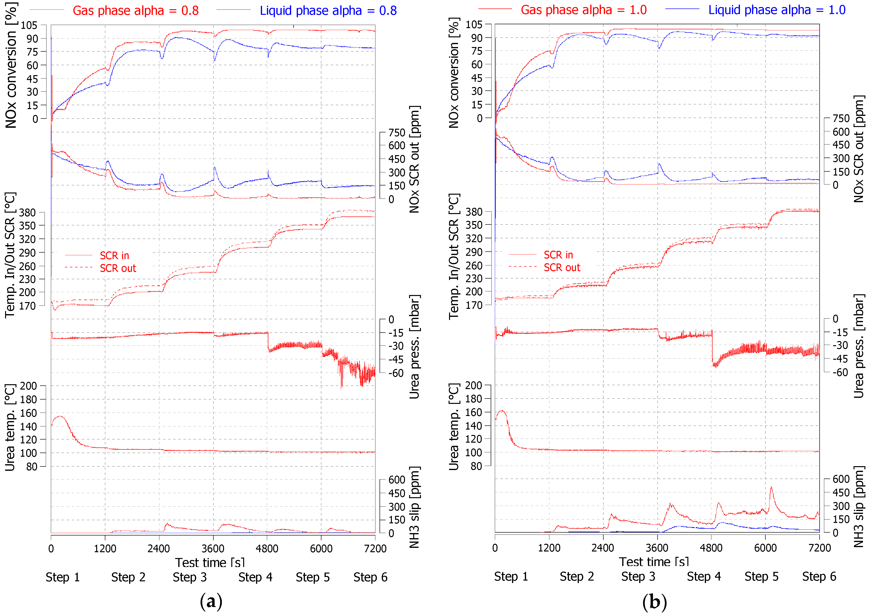
The Figure 1 presents comparisons of test results obtained under steady-state engine operation according to test steps as determined in Table 1. The resulting evaluations aim to compare the NOx conversion efficiency as a function of the urea-dosing method applied. It was found that the gaseous urea system brought a significant benefit in terms of NOx reduction in nearly the entire cycle range. That was further confirmed by test cycles run at a different α value.
One of the critical parameters related to the gas-phase concept was the urea–water solution (UWS) temperature level obtained at the outlet of the heating chamber. The UWS temperature rapidly rose at the beginning of step 1, reaching its maximum of 160 °C, and later stabilised at around 110 °C. Across all the remaining test steps, the UWS temperature steadily decreased down to a value of 103 °C, measured at the end of the test run. The UWS temperature consistently declined, as the heating chamber was more and more intensively cooled down by urea flow, which increased its rate with each test step. The heating power delivered to the chamber was, on the other hand, maintained at a constant level.
As the evaporation of water was known to be independent of the urea evaporation [13,14], a point of interest was the composition of the feed-gas dosed upstream of SCR catalyst.
Before chemical reactions occur, the dosed UWS aerosol is heated up in an evaporation chamber and later by the surrounding exhaust gas that contains evaporated water. The exact state of aggregation of urea during decomposition is still uncertain [15,16]. Two recent theoretical studies [17,18] relying on experimental data point toward urea evaporation from liquid aerosols and decomposition in the gas phase. However, another recent study supposed that the mentioned chemical reactions take place in solid aerosols [19].
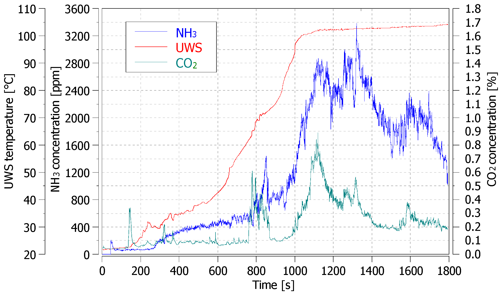
At the UWS temperature ranging from 160 °C to 103 °C, the water content vaporizes as well as the urea vaporisation and decomposition processes taking place. Figure 2 presents the results of an experiment of heating up the UWS in an open vessel. It was found that urea decomposition to NH3 and CO2 occurred also at temperatures below 103 °C [12].
The biggest impact of the gaseous urea system on NOx reduction was obtained at α ratio 0.8, and in that case, the decrease in total value of NOx emission [g/kWh] reached 60%. In the initial phase of the test, corresponding to the lowest gas temperature of 170 °C, the NOx conversion value for the gaseous urea system was significantly lower than that for the liquid counterpart. The decrease in performance was due to the time delay of gaseous urea reaching the exhaust gas upstream of the SCR. There was the necessity of heating the chamber saturated with urea. The NOx conversion for gaseous urea subsequently increased and remained greater than that for the liquid-urea dosing until the end of the test. The difference in NOx traces for both dosing methods was greatest in the middle and upper range of exhaust-gas temperature (steps 3 to 6). The ammonia slip downstream of the SCR catalyst was also measured. It was found to be greater for the gaseous urea system for both α = 0.8 and α = 1.0, and that phenomenon needs to be further investigated. The exhaust line was not equipped with a clean-up catalyst (CUC) to oxidise excessive ammonia, and therefore, sudden release of NH3 was noted with the gas-temperature increase. The NH3 storage capacity of an SCR catalyst is inversely proportional to its temperature, and therefore, the greater the temperature the less NH3 can be stored inside the catalyst [20,21,22]. The NH3 concentration measured downstream of the SCR was greater for the gaseous urea system for both α = 0.8 and α = 1.0. The reason behind that was presumably greater urea-to-NH3 conversion for the gaseous urea system, that is, the key point of the concept. In order to explain this phenomenon, ammonia-mass calculations based upon measured NOx and NH3 concentrations downstream of the SCR, and the amount of urea injected, were carried out. The results are presented in Table 2.
It was found that for the gas-phase system, the amount of NH3 obtained from urea was 10% greater than that from the liquid-phase solution. The excessive (compared to liquid solution) ammonia was accumulated in the SCR catalyst, especially at the initial phase of the test run at low gas temperature, and later released, causing a greater slip.
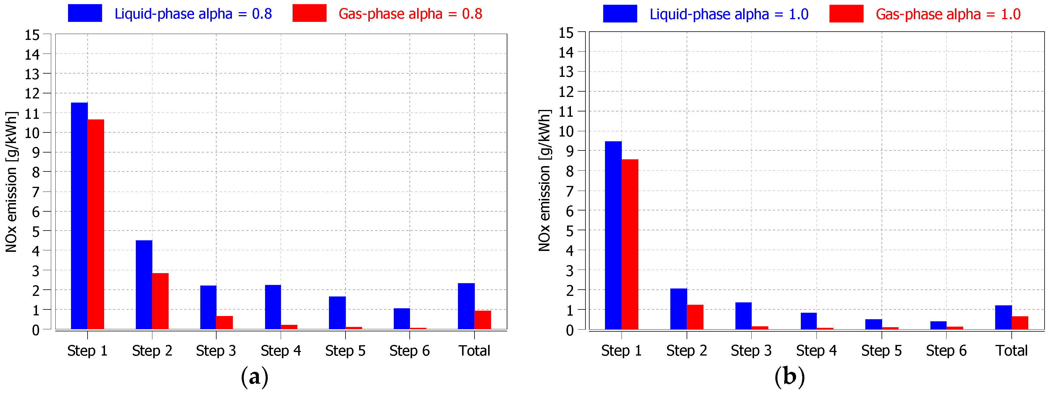
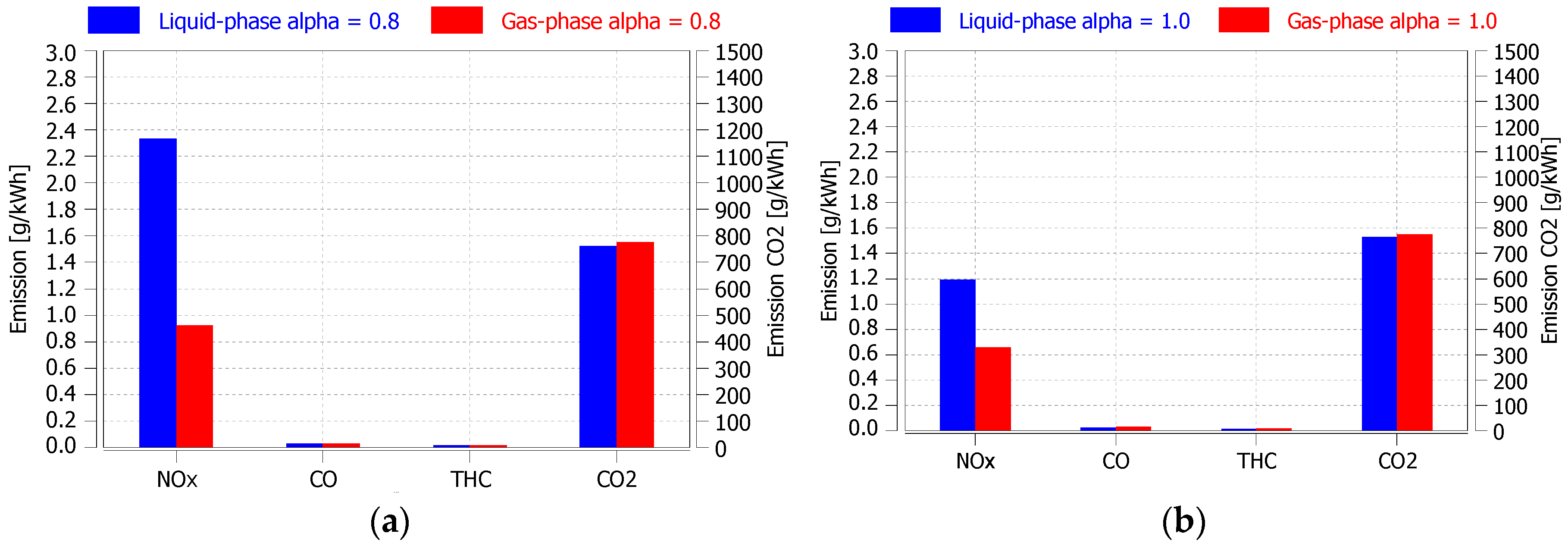
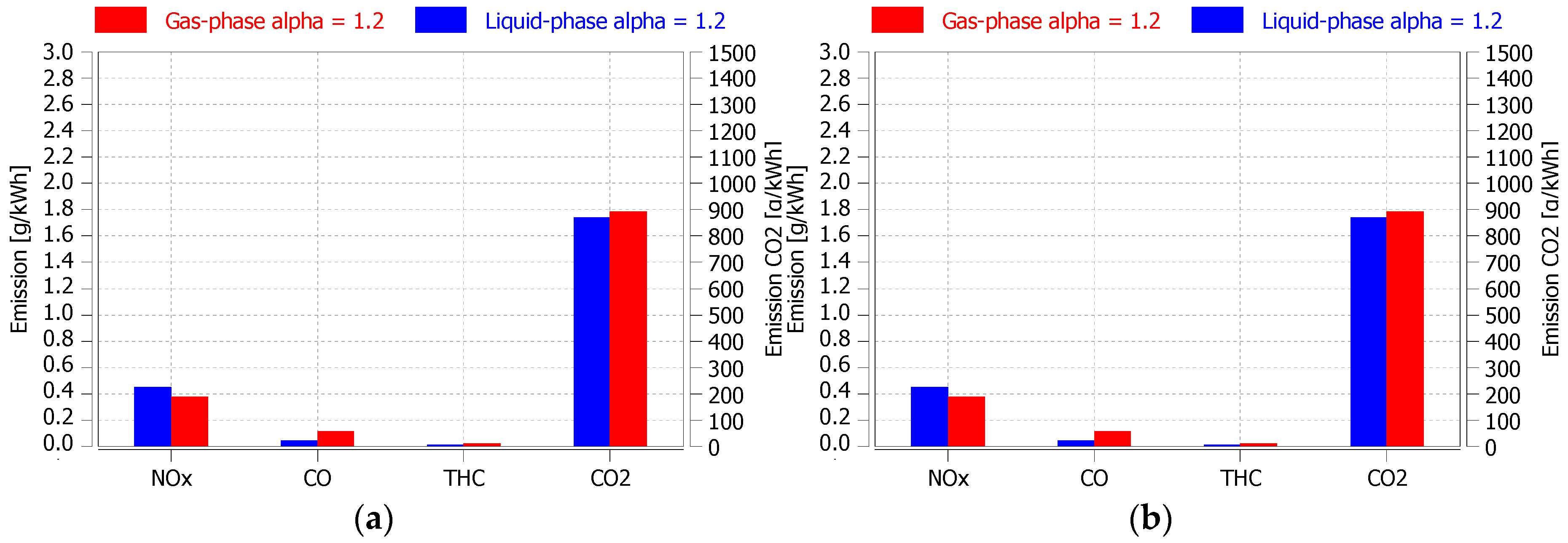
Figure 3 presents a comparison of results of NOx emissions for individual test steps and the total value. Improvement in NOx reduction was achieved for all test steps and both α values. Total NOx emission was lower by 60% at α = 0.8 and by 45% at α = 1.0. Other emission compounds, expressed in [g/kWh], are shown in Figure 4. The measured CO2 emission value was greater in the case of the gaseous urea system for both α values, explained by increased exhaust-gas backpressure caused by the mixing element introducing gaseous urea upstream of the SCR catalyst. The mixing element was a Venturi-type orifice narrowed in a section where the heating chamber was connected and causing exhaust gas to increase in speed, creating a pressure drop. It was also noticed that the CO emission was slightly higher for the gaseous urea solution, while the total hydrocarbons (THC) values remained at a similar level for both urea-dosing methods.
3.2. Transient Engine Operation
Part of the study included concept-system verification under transient conditions. Figure 5b presents calculated emission results of the WHTC cycle with hot-engine start. The NOx emission was found to be 18% lower for the gaseous urea system (α = 1.2), while the CO2 and NH3 emissions were consequently higher. Traces of NOx conversion, gas temperature and ammonia are shown in Figure 5a. The NH3 slip was measured in the last part of the test cycle at high gas-temperature range. It occurred at about 1300 s into the test and lasted until test completion. The NH3 concentration was higher for the gaseous urea system.
Based on those test results, it was found that application of the gaseous urea system had a positive impact on decreasing NOx, but it was disadvantageous for CO2 and NH3 emission.
3.3. Practical Implementation
The analysis of test results raises a question of possible application of the gaseous urea concept. The idea of dosing NOx reductant in the gas phase is currently the subject of research work and it is seen as a solution for decreasing or eliminating issues related to poor urea evaporation, inefficient ammonia and urea conversion, and deposit formation, when SCR is operated at low exhaust-gas temperature [14].
The key observations made in the course of the study were the following.
Firstly, for urea heat-up and evaporation, electric energy was applied at a power of 200 W. In that case, this level of power was suitable to evaporate mainly the water in urea solution, although it needs to be correlated with urea flow-rate for obtaining best results.
Secondly, urea introduction into the gas stream via a mixing element unit has become an issue due to the accompanying increase in backpressure. An optimization and redesign of the mixing element is required. The properties of material that the mixing element is made of might influence the rate of thermal urea decomposition. Optimized selection of material composition could be advantageous for enhancing urea-to-ammonia conversion.
Thirdly, the start-up conditions of the gaseous urea system remain to be improved. At certain engine operating points, solid urea-deposit formation started to occur inside the heating chamber.
4. Concept Description
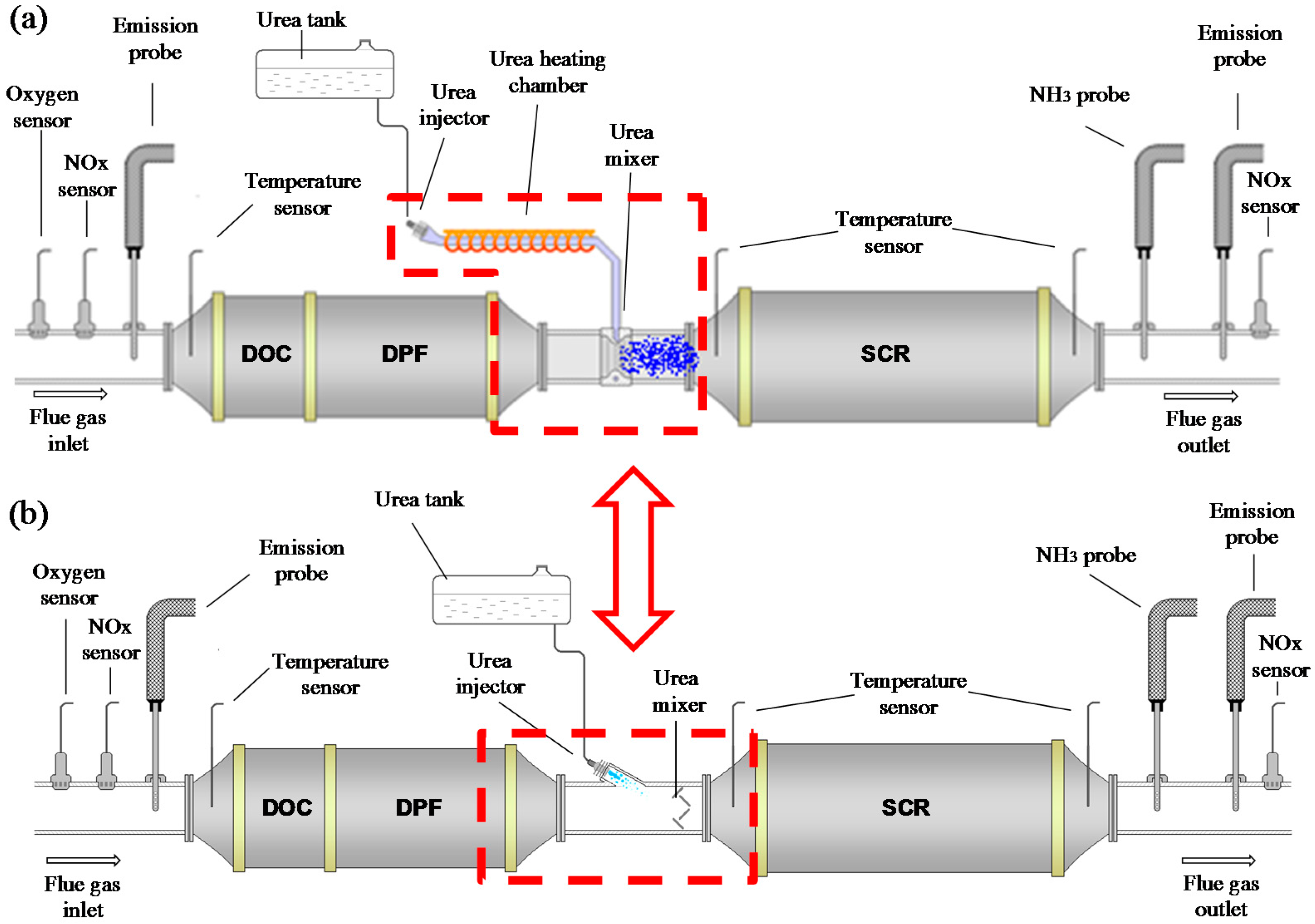
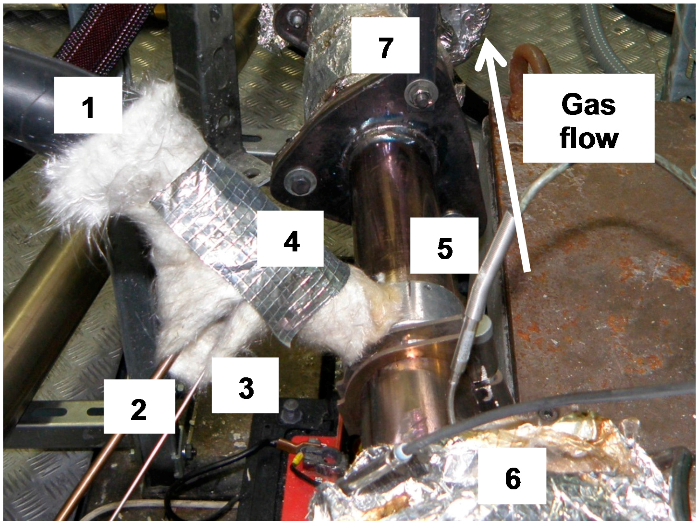
The studies on concept gaseous urea dosing systems were performed in an engine-testing laboratory on a 3.0 L CI Euro V medium-duty engine. The exhaust line consisted of a diesel oxidation catalyst (DOC), diesel particle filter (DPF), both belonging to tested engine type and an Fe–zeolite SCR catalyst combined with a development urea-dosing system. The dosing system was based on Siemens NOx sensors, Bosch urea injector, while the automation software was prepared by Bosmal. The solution allowed for fast changeover between concept (gas) and standard (liquid) urea-dosing methods. The core of the concept method was to heat up and evaporate the urea water solution (UWS) in a special heating chamber prior to its introduction into the exhaust gas stream at the SCR inlet. For this purpose, an external energy source was utilized. Figure 6a depicts the exhaust line with the inbuilt gaseous urea concept implemented on an engine test bed. Figure 7 presents physical realisation of the system. The urea heating chamber was supplied with electrical energy with a heating power of 200 W [12].
The gaseous urea dosing system utilized a standard OEM urea Bosch injector, which dosed liquid urea into a thermally insulated heating chamber of tubular shape with a diameter of 10 mm. Urea vapours were then subsequently drawn down by the pressure drop induced by the mixing element mounted upstream of the SCR catalyst. The mixing element was made of aluminium alloy, while the heating chamber was equipped with a thermostatic temperature control set to 220 °C. During test runs, urea vapour pressure and temperature were measured at the outlet of the heating chamber.
The standard urea dosing system is depicted in Figure 6b. The NOx reductant was injected in the liquid phase directly into the exhaust gas stream. The urea mixer is typically used for providing good ammonia uniformity in the SCR catalyst. The mixer is placed between the urea injector and the SCR brick. It is made of fixed-geometry metal blades to help urea droplets break up [23,24,25].
The demanded value of urea-mass injected was realized in either open or closed-loop transfer functions. In the open loop, the urea injection took fixed values, while in the closed loop it was expressed by the α ratio. The α value was calculated by the control unit as the function of the actual exhaust-mass flow rate and the NOx concentration value measured by the portable NOx sensor. The sensor was mounted at the engine outlet. The urea was dispensed at a pressure of approximately 5 bar, depending on the dosing-system configuration: directly into the exhaust gas stream (liquid) or into the heating chamber (gas).
The main part of the study was carried out at steady-state engine operation. A dedicated test procedure was prepared that covered as wide a range of exhaust-gas temperatures as possible. The procedure was applied to the concept and standard urea-dosing methods in order to compare their respective performance. The test consisted of six 20-min test steps lasting two hours in total. The gas temperature measured at the SCR inlet ranged from 180 °C to 380 °C and was increased by approximately 40 °C at each subsequent step, starting from 180 °C. The engine speed was set to a constant value of 1900 rpm and the gas temperature was controlled by varying engine load in the range form 60 to 400 Nm. The EGR valve remained shut-off during testing, and therefore, the NOx concentration in the raw gas was high, varying from 580 ppm to 1100 ppm. Exhaust mass flow varied within the range 230 to 400 kg/h.
The quantity of urea dosed was expressed by the α ratio, defined as the quotient of the amount of ammonia molecules derived from the reducing agent (NH3) and the amount of nitrogen oxides molecules (NOx) present in the elementary exhaust gas mass flow.
Steady-state testing was carried out at α values of 0.8 and 1.0. The exhaust emission and gas temperature were measured continuously (at 1 Hz) upstream of the DOC and downstream of the SCR, where the ammonia concentration was also measured. The exhaust emission bench was an AVL AMA i60 measurement system with standalone ammonia analyser with an accuracy of ±1%. The injected urea flow-rate was expressed in mg/s.
Before commencing testing, the exhaust line underwent a pre-conditioning cycle to ensure stability and repeatability of initial conditions and to eliminate ammonia saturation of the SCR catalyst. The cycle was run at a high gas-temperature generated by engine load and with the urea dosing system remaining switched off.
The work was extended to evaluate the gaseous urea-dosing systems also in engine transient conditions. To do that, the World Harmonized Transient Cycle (WHTC) was chosen and run in a simplified version on eddy-current dynamometer. The hot-start WHTC test was only taken into consideration.
5. Conclusions
The SCR method still requires further development work, especially when operated under engine warm-up and idle conditions. Urea injection at low exhaust-gas temperature is critical due to the limited ability of evaporation and chemical decomposition into ammonia.
The purpose of this study was to evaluate an effect of a water–urea solution preparation on NOx conversion in an SCR catalyst. The preparation process relies on urea heating up and evaporating prior to its introduction upstream of the SCR catalyst. An expected effect was to accelerate urea thermal decomposition and ultimately to increase NOx conversion efficiency and possibly reduce urea consumption.
A custom-made gas-urea system was designed and constructed and put under test. Although it was a very simple solution that needed further development, it gave an insight into the benefits that can be achieved by urea vaporization.
It was found that the gaseous urea-dosing method had significantly increased the NOx conversion in the SCR catalyst compared to standard (liquid) urea-dosing. The benefits were achieved under both steady-state and dynamic engine conditions.
The work carried out demonstrated the potential of a gaseous urea concept for an SCR application, and the results obtained serve as a great incentive for undertaking further research in that field.
Acknowledgments
This work was financed and carried out in Engine Testing Laboratory at BOSMAL R&D Institute based in Bielsko-Biala, Poland and was a part of a PhD dissertation.
Author Contributions
For research articles with several authors, a short paragraph specifying their individual contributions must be provided. R.S. and M.B. conceived and designed the experiments; R.S. performed the experiments; R.S. and M.B. analyzed the data; P.B. contributed reagents and materials; R.S. wrote the paper.
Conflicts of Interest
The authors declare no conflict of interest.
References
- Yang, L.; Franco, V.; Campestrini, A.; German, J.; Mock, P. NOx Control Technologies for Euro 6 Diesel Passenger Cars; ICCT, White Paper: Washington, DC, USA, 2015. [Google Scholar]
- Brzezanski, M.; Sala, R. In-service problems of selective catalytic reduction systems for reduction of nitrogen oxides. Combus. Engines 2013, 154, 969–976. [Google Scholar]
- Brzezanski, M.; Sala, R. A study on the indirect urea dosing method in the Selective Catalytic Reduction system. In Proceedings of the Scientific Conference on Automotive Vehicles and Combustion Engines, Materials Science and Engineering, (KONMOT 2016), Krakow, Poland, 22–26 September 2016; Volume 148. [Google Scholar]
- Bielaczyc, P.; Woodburn, J. Current directions in LD powertrain technology in response to stringent exhaust emissions and fuel efficiency requirements. Combus. Engines 2016, 166, 62–75. [Google Scholar] [CrossRef]
- Merkisz, J.; Pielecha, J.; Bielaczyc, P.; Woodburn, J. Analysis of Emission Factors in RDE Tests as Well as in NEDC and WLTC Chassis Dynamometer Tests; No. 2016-01-0980; SAE Technical Paper: Washington, DC, USA, 2016. [Google Scholar]
- European Environment Agency (EEA). Exceedance of Air Quality Limit Values in Urban Areas; European Environment Agency: Copenhagen, Denmark, 2015. [Google Scholar]
- Yang, L.; Franco, V.; Mock, P.; Kolke, R.; Zhang, S.; Wu, Y.; German, J. Experimental assessment of NOx emissions from 73 Euro 6 diesel passenger cars. Environ. Sci. Technol. 2015, 49, e14409–e14415. [Google Scholar] [CrossRef] [PubMed]
- Johnson, T. Vehicular Emissions in Review. SAE Int. J. Engines 2016, 9, 1258–1275. [Google Scholar] [CrossRef]
- Maunula, T. NOx Reduction with the Combinations on LNT and SCR in Diesel Applications; No. 2013-24-0161; SAE Technical Paper: Washington, DC, USA, 2013. [Google Scholar]
- Chi, J. Control Challenges for Optimal NOx Conversion Efficiency from SCR Aftertreatment Systems; No. 2009-01-0905; SAE Technical Paper: Washington, DC, USA, 2009. [Google Scholar]
- Marotta, A.; Pavlovic, J.; Ciuffo, B.; Serra, S.; Fontaras, G. Gaseous emissions from Light-Duty Vehicles: Moving from NEDC to the new WLTP test procedure. Environ. Sci. Technol. 2015, 49, 8315–8322. [Google Scholar] [CrossRef] [PubMed]
- Sala, R. Wpływ Sposobu Dozowania Roztworu Mocznika na Sprawność Selektywnej Redukcji Katalitycznej (The Influence of the Urea Dosing Method on the Efficiency of the Selective Catalytic Reduction Process). Ph.D. Thesis, Cracow University of Technology, Cracow, Poland, 2014. [Google Scholar]
- Bernhard, A.M.; Czekaj, I.; Elsener, M.; Wokaun, A.; Kröcher, O. Evaporation of Urea at Atmospheric Pressure. J. Phys. Chem. A 2011, 115, 2581–2589. [Google Scholar] [CrossRef] [PubMed]
- Kröcher, O.; Elsener, M.; Jacob, E. A model gas study of ammonium formate, methanamide and guanidinium formate as alternative ammonia precursor compounds for the selective catalytic reduction of nitrogen oxides in diesel exhaust gas. Appl. Catal. B 2009, 88, 66–82. [Google Scholar] [CrossRef]
- Birkhold, F.; Meingast, U.; Wassermann, P.; Deutschmann, O. Modeling and simulation of the injection of urea-water-solution for automotive SCR DeNOx-systems. Appl. Catal. B 2007, 70, 119–127. [Google Scholar] [CrossRef]
- Ström, H.; Lundström, A.; Andersson, B. Choice of urea-spray models in CFD simulations of urea-SCR systems. Chem. Eng. J. 2009, 150, 69–82. [Google Scholar] [CrossRef]
- Abu-Ramadan, E.; Saha, K.; Li, X. Modeling the depleting mechanism of urea-watersolution droplet for automotive selective catalytic reduction systems. AlChE J. 2011, 57, 3210–3225. [Google Scholar] [CrossRef]
- Lundström, A.; Waldheim, B.; Ström, H. Modelling of urea gas phase thermolysis and theoretical details on urea evaporation. Proc. Inst. Mech. Eng. Part D J. Autom. Eng. 2011, 255, 1392–1398. [Google Scholar] [CrossRef]
- Ebrahimian, V.; Nicolle, A.; Habchi, C. Detailed modeling of the evaporation and thermal decomposition of urea-water solution in SCR systems. AIChE J. 2012, 58, 1998–2009. [Google Scholar] [CrossRef]
- Gong, J.; Narayanaswamy, K.; Rutland, C.J. Heterogeneous Ammonia Storage Model for NH3–SCR Modeling. Ind. Eng. Chem. Res. 2016, 55, 5874–5884. [Google Scholar] [CrossRef]
- Seneque, M.; Can, F.; Duprez, D.; Courtois, X. NOx Selective Catalytic Reduction (NOx-SCR) by Urea: Evidence of the Reactivity of HNCO, Including a Specific Reaction Pathway for NOx Reduction Involving NO + NO2. ACS Catal. 2016, 6, 4064–4067. [Google Scholar] [CrossRef]
- Karjalainen, P.; Ronkko, T.; Lahde, T.; Rostedt, A.; Keskinen, J.; Saarikoski, S.; Aurela, M.; Hillamo, R.; Malinen, A.; Pirjola, L.; et al. Reduction of heavy-duty diesel exhaust particle number and mass at low exhaust temperature driving by the DOC and the SCR. SAE Int. J. Fuels Lubr. 2012, 5, e1114–e1122. [Google Scholar] [CrossRef]
- Koebel, M.; Strutz, E.O. Thermal and Hydrolytic Decomposition of Urea for Automotive Selective Catalytic Reduction Systems: Thermochemical and Practical Aspects. Ind. Eng. Chem. Res. 2003, 42, 2093–2100. [Google Scholar] [CrossRef]
- Sung, D.Y.; Soo, J.K.; Joon, H.B.; In-Sik, N.; Young, S.M.; Jong-Hwan, L.; Byong, K.C.; Se, H.O. Decomposition of Urea into NH3 for the SCR Process. Ind. Eng. Chem. Res. 2004, 43, 4856–4863. [Google Scholar] [CrossRef]
- Kleemann, M.; Elsener, M.; Koebel, M.; Wokaun, A. Hydrolysis of Isocyanic Acid on SCR Catalysts. Ind. Eng. Chem. Res. 2000, 39, 4120–4126. [Google Scholar] [CrossRef]
Figure 1.
Comparison of results of standard and gaseous urea dosing at α = 0.8 (a) and α = 1.0 (b).

Figure 2.
Results of NH3 and CO2 concentration measured over urea–water solution heat-up.

Figure 3.
NOx emission results for standard and gaseous urea dosing at α = 0.8 (a) and α = 1.0 (b).

Figure 4.
Emission results of gas and standard urea dosing at α = 0.8 (a) and α = 1.0 (b).

Figure 5.
Comparison test results of liquid and gaseous urea-dosing on World Harmonized Transient Cycle (WHTC), hot-cycle at α = 1.2, (a) modal analysis, (b) emission results.
Figure 5.
Comparison test results of liquid and gaseous urea-dosing on World Harmonized Transient Cycle (WHTC), hot-cycle at α = 1.2, (a) modal analysis, (b) emission results.

Figure 6.
Comparison of SCR systems: (a) gaseous urea dosing, (b) liquid urea dosing.

Figure 7.
Gaseous urea dosing system: 1—heating chamber, 2—urea pressure port, 3—urea temperature port, 4—insulated tube, 5—mixing element, 6—DPF filter, 7—SCR catalyst.
Figure 7.
Gaseous urea dosing system: 1—heating chamber, 2—urea pressure port, 3—urea temperature port, 4—insulated tube, 5—mixing element, 6—DPF filter, 7—SCR catalyst.


Table 1.
Engine operation points during steady-state test cycle.
| Test Step Number | SCR Inlet Gas Temp. (°C) | Engine Load (Nm) |
|---|---|---|
| Step 1 | 180 | 60 |
| Step 2 | 214 | 82 |
| Step 3 | 255 | 111 |
| Step 4 | 308 | 180 |
| Step 5 | 344 | 316 |
| Step 6 | 380 | 400 |
Table 2.
Ammonia-mass calculations for standard and gaseous urea dosing at α = 1.0.
| Amount of NH3 Reacted (g) | Amount of NH3 Dosed (g) | Percentage of NH3 Reacted (%) | |
|---|---|---|---|
| Gas phase | 252 | 426 | 59 |
| Liquid phase | 185 | 374 | 49 |
© 2017 by the authors. Licensee MDPI, Basel, Switzerland. This article is an open access article distributed under the terms and conditions of the Creative Commons Attribution (CC BY) license (http://creativecommons.org/licenses/by/4.0/).
Share and Cite
MDPI and ACS Style
Sala, R.; Bielaczyc, P.; Brzezanski, M. Concept of Vaporized Urea Dosing in Selective Catalytic Reduction. Catalysts 2017, 7, 307. https://doi.org/10.3390/catal7100307
AMA Style
Sala R, Bielaczyc P, Brzezanski M. Concept of Vaporized Urea Dosing in Selective Catalytic Reduction. Catalysts. 2017; 7(10):307. https://doi.org/10.3390/catal7100307
Chicago/Turabian StyleSala, Rafal, Piotr Bielaczyc, and Marek Brzezanski. 2017. "Concept of Vaporized Urea Dosing in Selective Catalytic Reduction" Catalysts 7, no. 10: 307. https://doi.org/10.3390/catal7100307
Note that from the first issue of 2016, this journal uses article numbers instead of page numbers. See further details here.