
Finite Element Analysis of a New Non-Engaging Abutment System for Three-Unit Implant-Supported Fixed Dental Prostheses

 , , , , ,
Abstract
: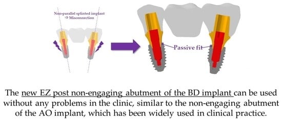
1. Introduction
2. Materials and Methods
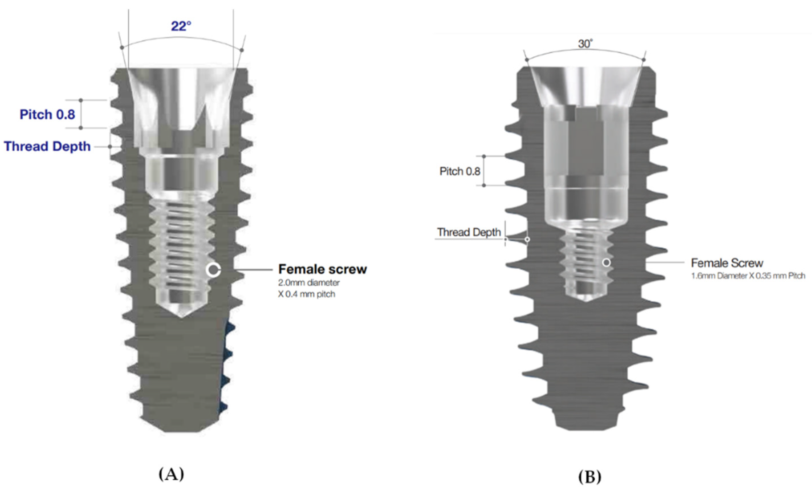
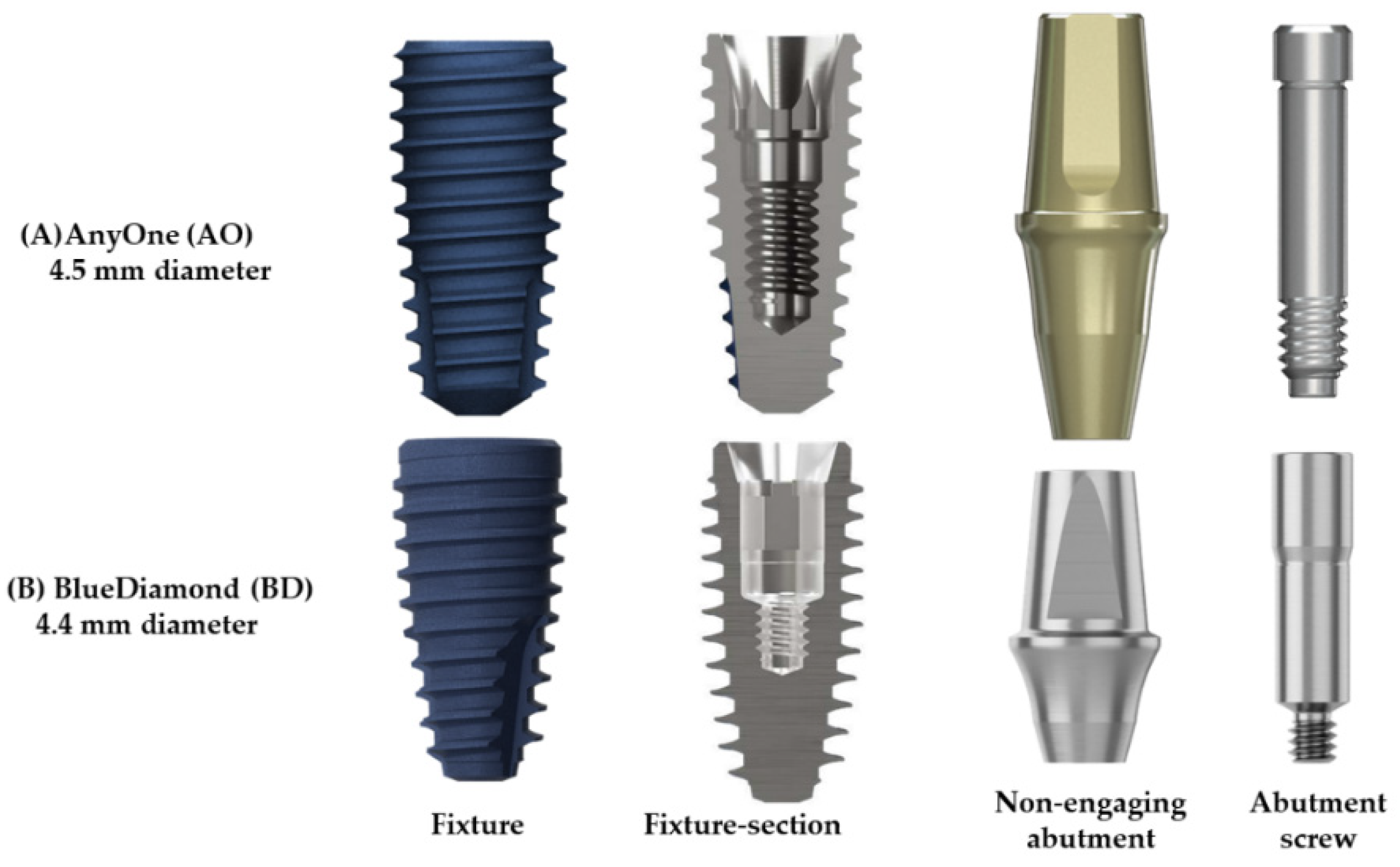
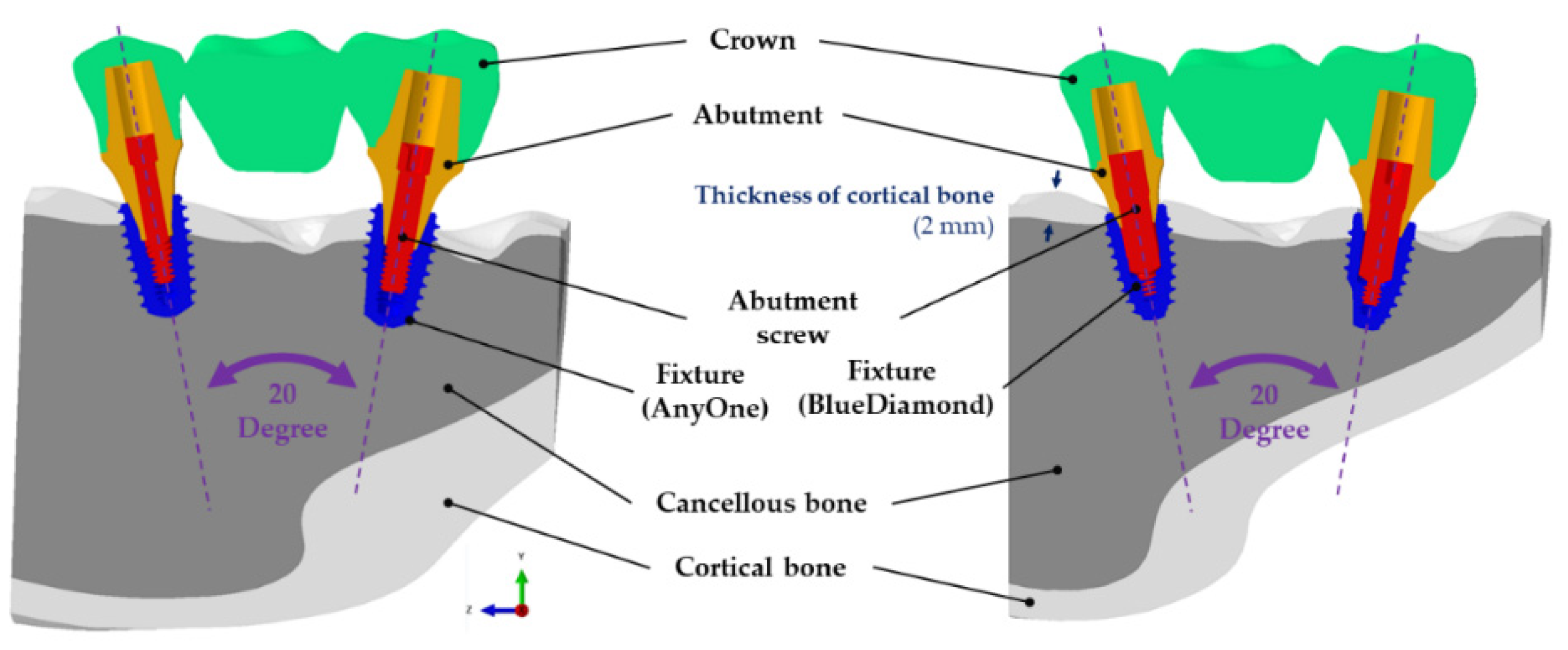
2.1. Design and Dimensions of the Fixture, Abutment, and Abutment Screw
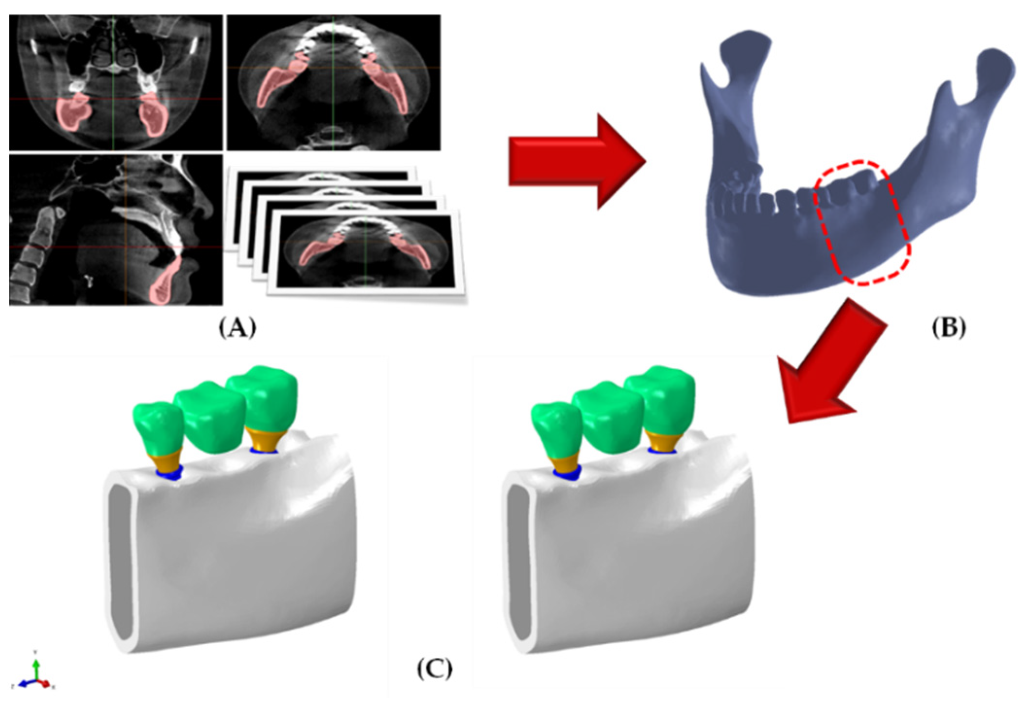
2.2. Bone Shape and Composition of Surgical Model
2.2.1. Finite Element Bone Shape Model
2.2.2. The Surgical Model Composition
2.3. Material Properties
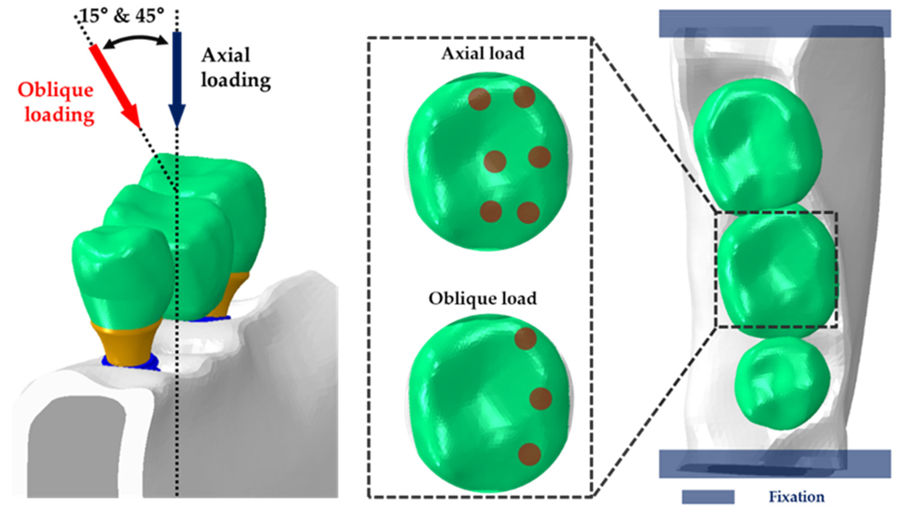
2.4. Loads, Boundaries, and Contact Conditions
2.5. Variables
3. Results
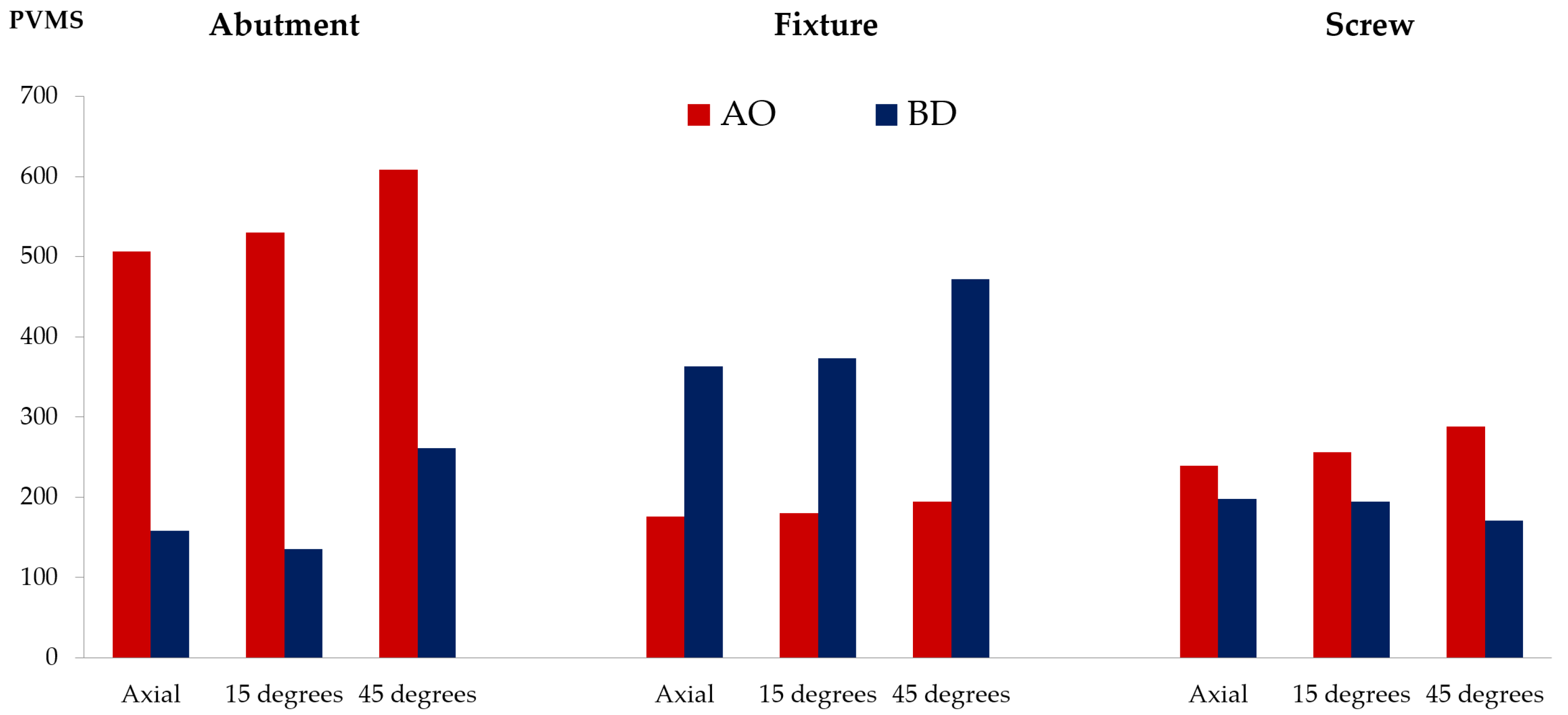
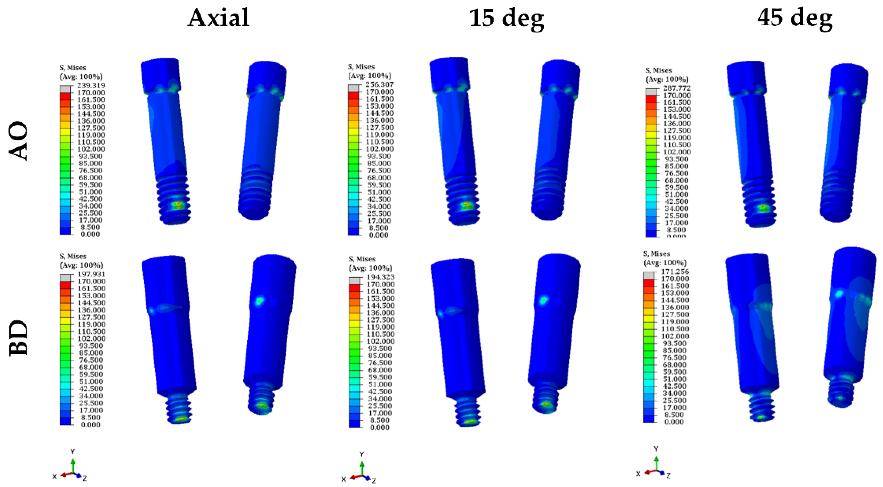
3.1. Stress on the Dental Implant System
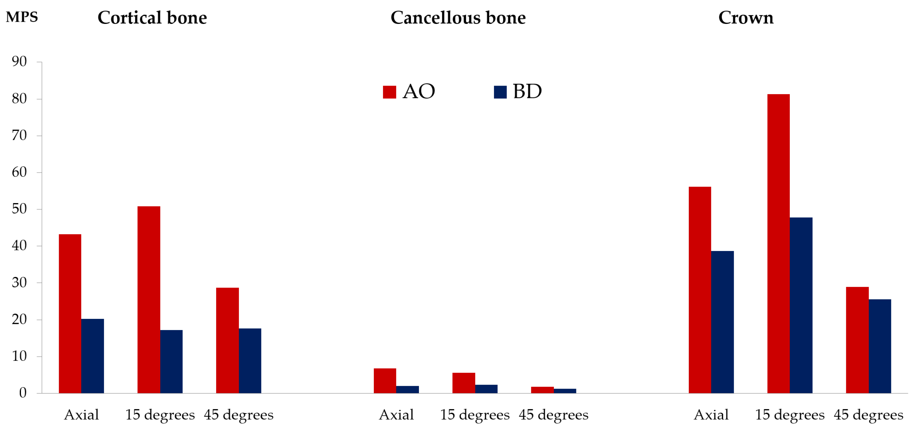
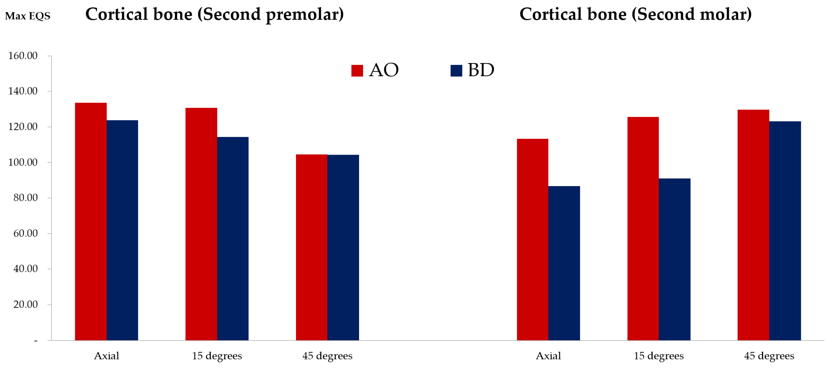
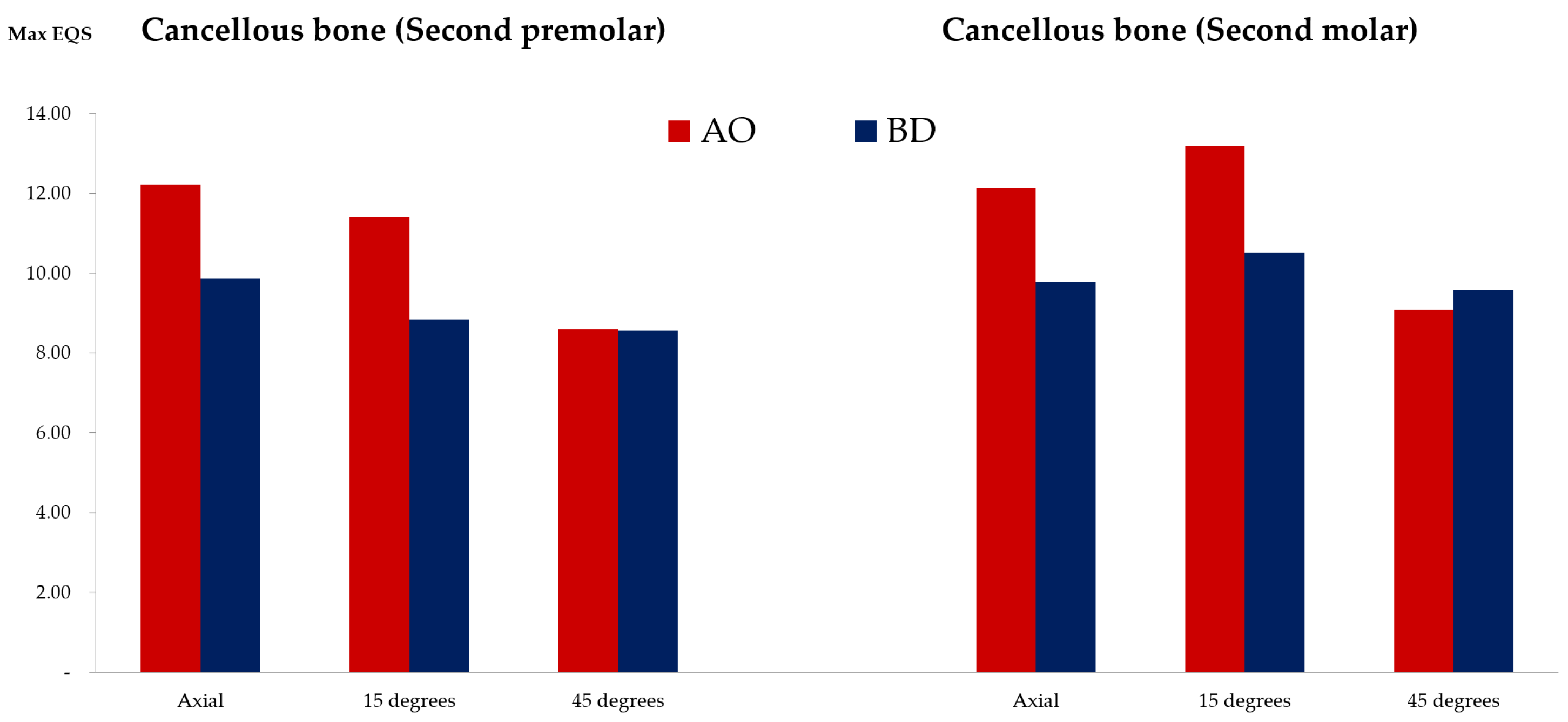
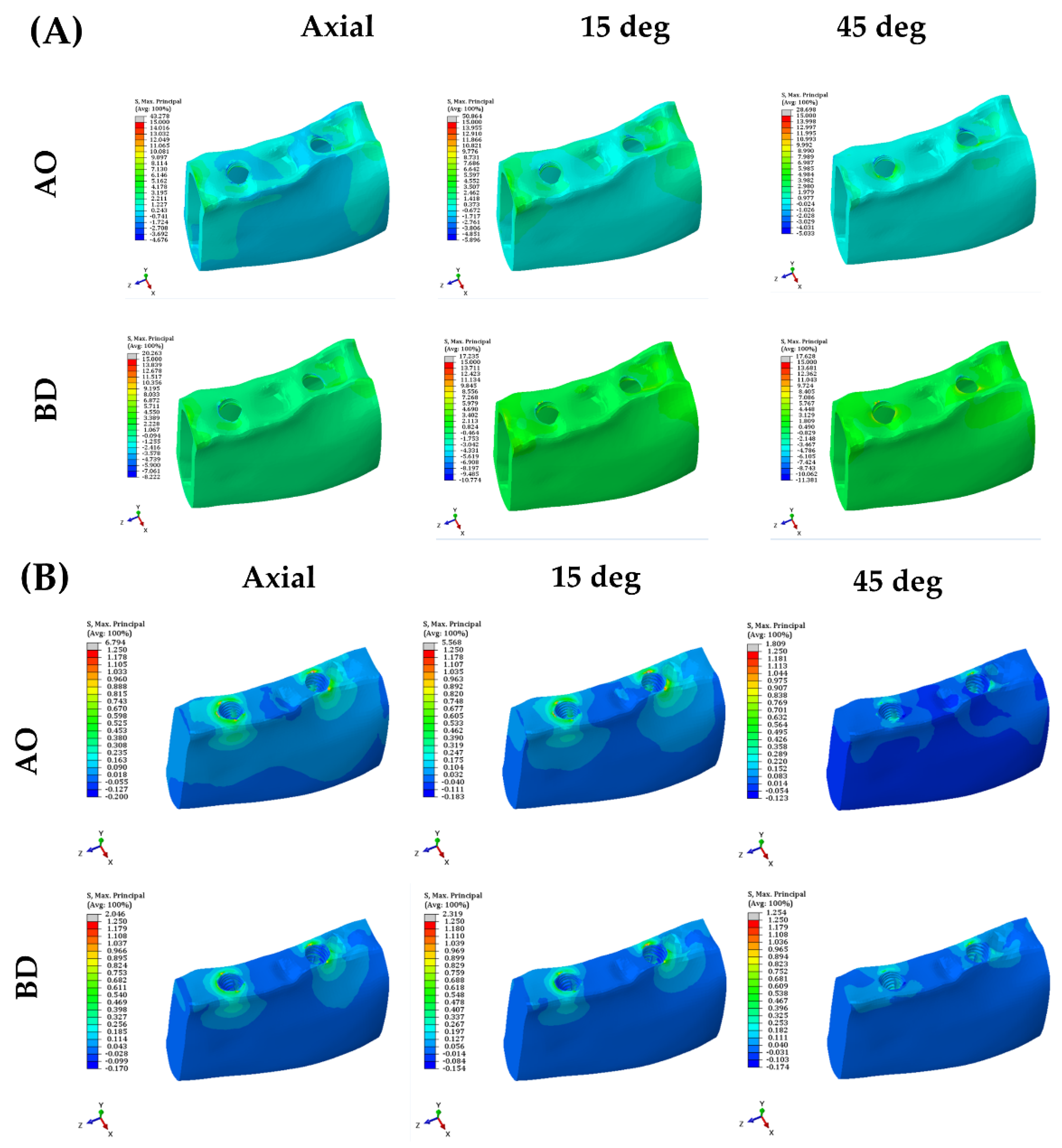
3.2. Stress on the Cortical Bone, Cancellous Bone, and Crown
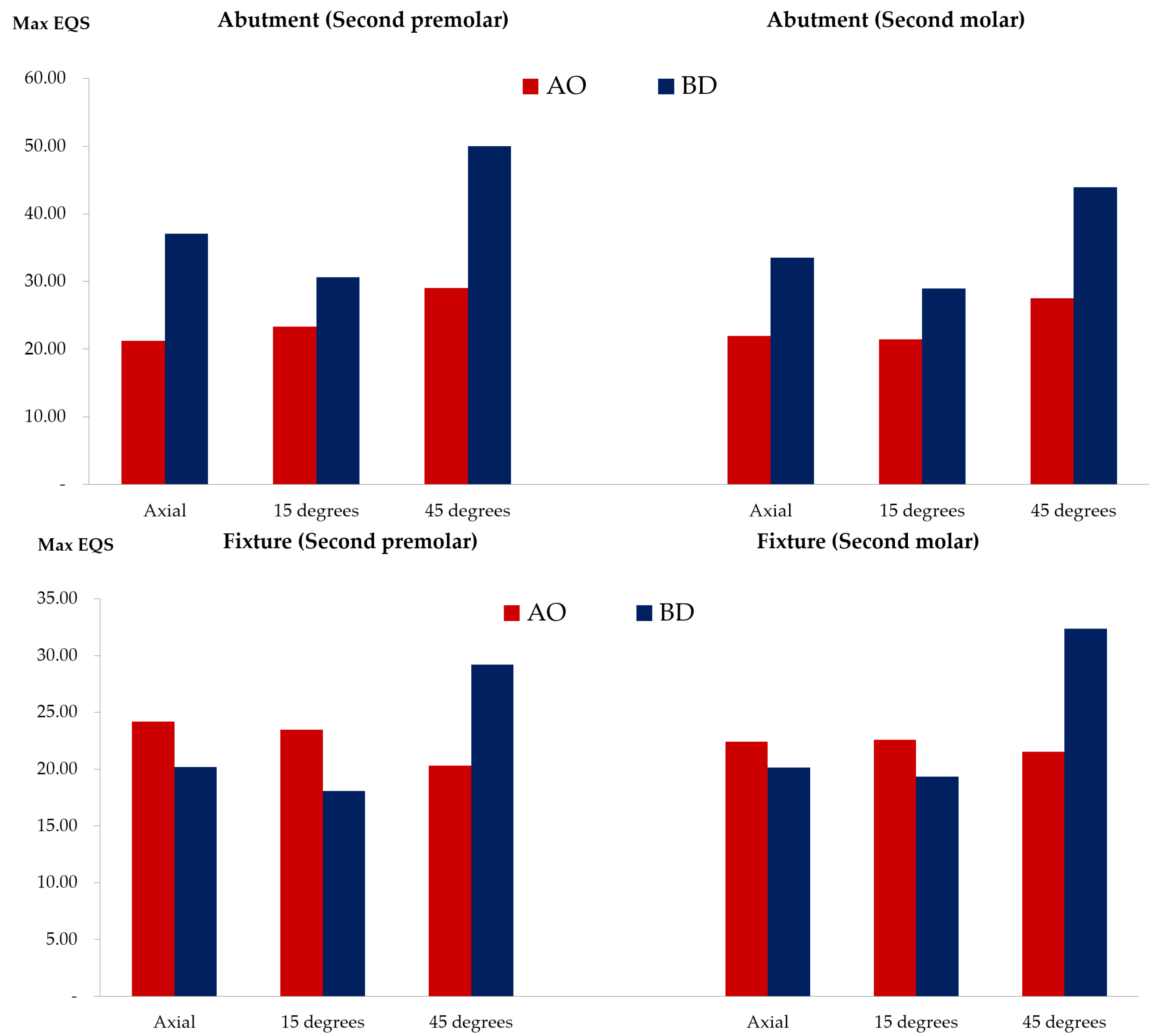
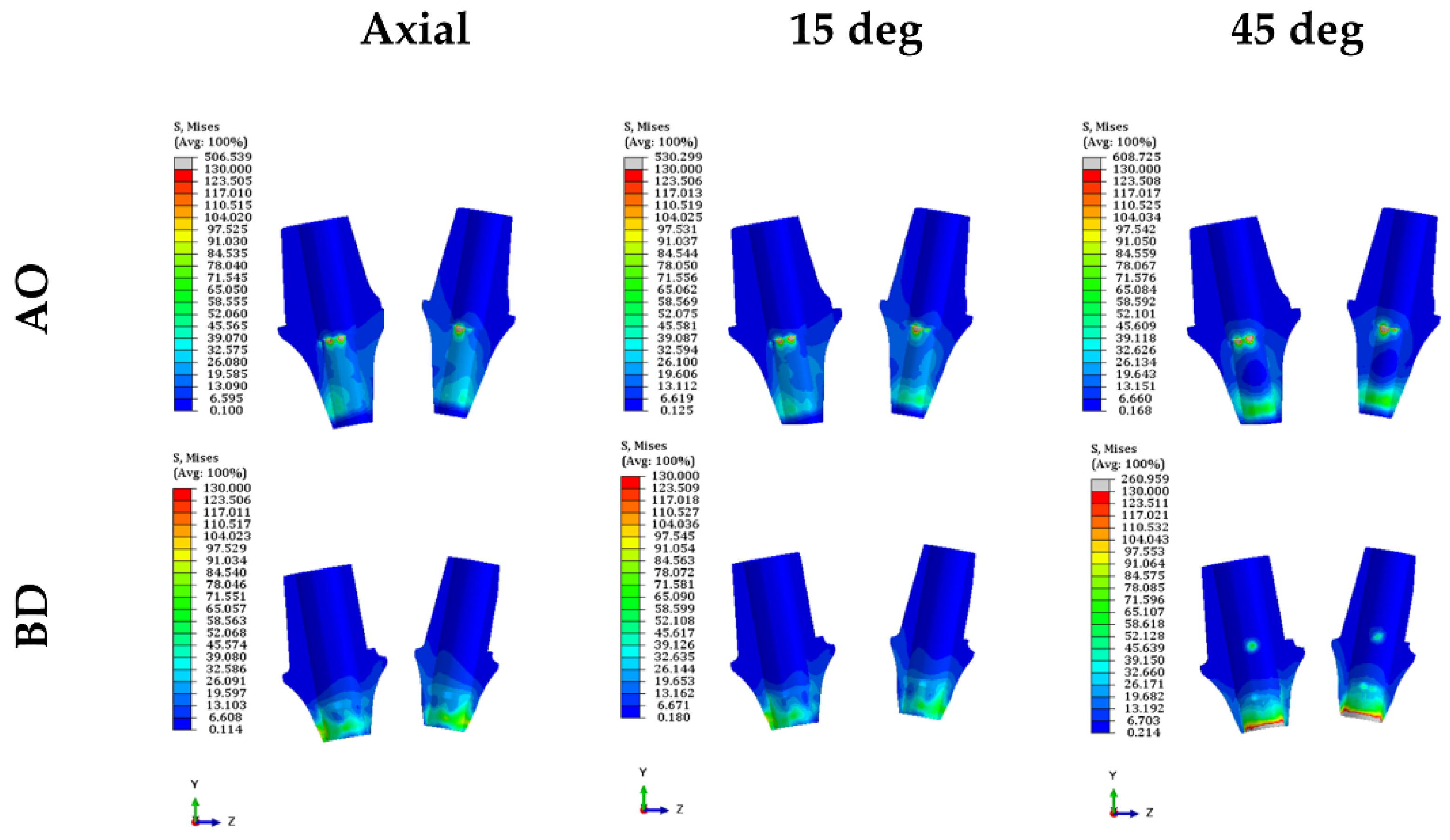
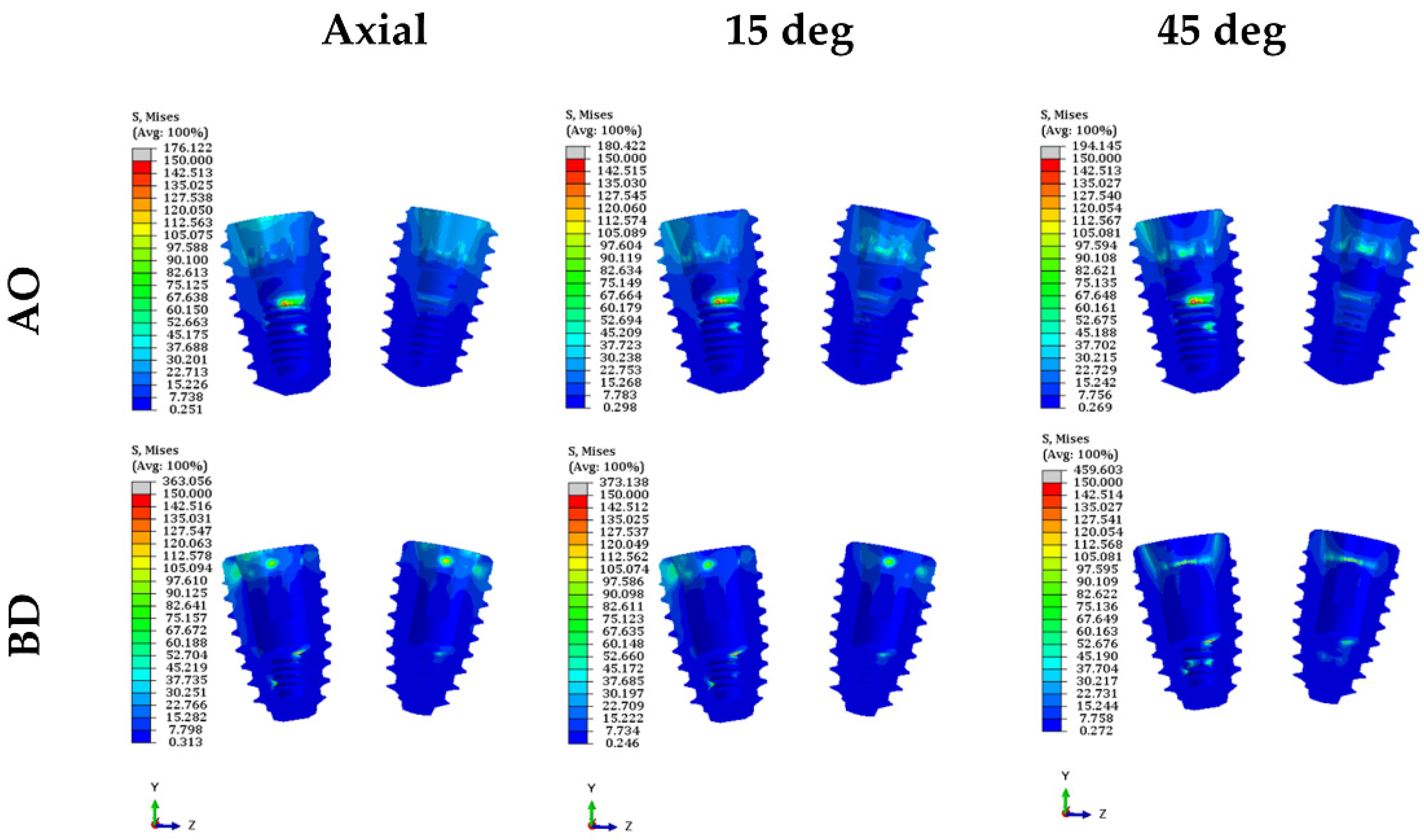
3.3. Stress on the Inner Surface of the Abutment and Fixture
3.4. Stress Results in the Surface of Cortical Bone and Cancellous Bone in Contact with the Fixture
4. Discussion
5. Conclusions
Supplementary Materials
Author Contributions
Funding
Institutional Review Board Statement
Informed Consent Statement
Data Availability Statement
Acknowledgments
Conflicts of Interest
References
- Kim, S.-B.; Lee, D.-H.; Lee, C.-H. Analysis of implant strain value exerted using different screw tightening protocols in screw-retained 3-unit prostheses. J. Korean Acad. Prosthodont. 2020, 58, 321–327. [Google Scholar] [CrossRef]
- Savignano, R.; Soltanzadeh, P.; Suprono, M.S. Computational Biomechanical Analysis of Engaging and Nonengaging Abutments for Implant Screw-Retained Fixed Dental Prostheses. J. Prosthodont. 2021, 30, 604–609. [Google Scholar] [CrossRef] [PubMed]
- Rangert, B.; Jemt, T. Forces and moments on Brånemark implants. Int. J. Oral Maxillofac. Implant. 1989, 4, 86–104. [Google Scholar]
- de Souza Batista, V.E.; Verri, F.R.; Lemos, C.A.; Cruz, R.S.; Oliveira, H.F.; Gomes, J.M.; Pellizzer, E.P. Should the restoration of adjacent implants be splinted or nonsplinted? A systematic review and meta-analysis. J. Prosthet. Dent. 2019, 121, 41–51. [Google Scholar] [CrossRef] [PubMed]
- Manzella, C.; Bignardi, C.; Burello, V.; Carossa, S.; Schierano, G. Method to improve passive fit of frameworks on implant-supported prostheses: An in vitro study. J. Prosthet. Dent. 2016, 116, 52–58. [Google Scholar] [CrossRef]
- Ko, K.-H.; Kang, H.-G.; Huh, Y.-H.; Park, C.-J.; Cho, L.-R. Concept and application of implant connection systems: Part I. Placement and restoration of internal conical connection implant. J. Dent. Rehabil. Appl. Sci. 2020, 36, 211–221. [Google Scholar] [CrossRef]
- Jeong, K.-W.; Kim, J.C.; Yeo, I.-S. Clinical Significance of Internal Friction Connection and Micro-Threads in Implant-Supported Prostheses: A Literature Review. Recent Prog. Mater. 2020, 2, 1. [Google Scholar] [CrossRef]
- Jo, S.-H.; Kim, K.-I.; Seo, J.-M.; Song, K.-Y.; Park, J.-M.; Ahn, S.-G. Effect of impression coping and implant angulation on the accuracy of implant impressions: An in vitro study. J. Adv. Prosthodont. 2010, 2, 128–133. [Google Scholar] [CrossRef]
- Kim, Y.-K.; Cho, Y.-S.; Kim, K.-S.; Kim, S.-W.; Lee, D.-H.; Oh, Y.-H.; Park, H.-W. Osstem Implant, 2nd ed.; Kim, Y.-K., Ed.; Osstem Implant Co., Ltd.: Seoul, Korea, 2013; p. 215. [Google Scholar]
- Ha, C.-Y.; Lim, Y.-J.; Kim, M.-J.; Choi, J.-H. The influence of abutment angulation on screw loosening of implants in the anterior maxilla. Int. J. Oral Maxillofac. Implant. 2011, 26, 45–55. [Google Scholar]
- Ozan, O.; Kurtulmus-Yilmaz, S. Biomechanical Comparison of Different Implant Inclinations and Cantilever Lengths in All-on-4 Treatment Concept by Three-Dimensional Finite Element Analysis. Int. J. Oral Maxillofac. Implant. 2018, 33, 64–71. [Google Scholar] [CrossRef]
- Janev, E.J.; Redzep, E.; Janeva, N.; Mindova, S. Multi Unit Abutments Recommended in Prosthetic and Surgical Implantology Treatment (Case Report). J. Morphol. Sci. 2020, 3, 65–72. [Google Scholar]
- Dogus, S.M.; Kurtz, K.S.; Watanabe, I.; Griggs, J.A. Effect of engaging abutment position in implant-borne, screw-retained three-unit fixed cantilevered prostheses. J. Prosthodont. Implant. Esthet. Reconstr. Dent. 2011, 20, 348–354. [Google Scholar] [CrossRef] [PubMed]
- Heo, Y.-K.; Lim, Y.-J.; Heo, Y.-K.; Lim, Y.-J. A Newly Designed Screw-and Cement-Retained Prosthesis and Its Abutments. Int. J. Prosthodont. 2015, 28, 612–614. [Google Scholar] [CrossRef] [Green Version]
- Buzayan, M.M.; Yunus, N.B. Passive fit in screw retained multi-unit implant prosthesis understanding and achieving: A review of the literature. J. Indian Prosthodont. Soc. 2014, 14, 16–23. [Google Scholar] [CrossRef] [PubMed]
- Lin, C.L.; Wang, J.C.; Chang, S.H.; Chen, S.T. Evaluation of Stress Induced by Implant Type, Number of Splinted Teeth, and Variations in Periodontal Support in Tooth-Implant–Supported Fixed Partial Dentures: A Non-Linear Finite Element Analysis. J. Periodontol. 2010, 81, 121–130. [Google Scholar] [CrossRef] [PubMed]
- Kim, W.H.; Song, E.S.; Ju, K.W.; Lee, J.-H.; Kim, M.Y.; Lim, D.; Kim, B. Finite element analysis of novel separable fixture for easy retrievement in case with peri-implantitis. Materials 2019, 12, 235. [Google Scholar] [CrossRef]
- Schwartz-Dabney, C.; Dechow, P. Edentulation alters material properties of cortical bone in the human mandible. J. Dent. Res. 2002, 81, 613–617. [Google Scholar] [CrossRef]
- Ha, S.-R. Biomechanical three-dimensional finite element analysis of monolithic zirconia crown with different cement type. J. Adv. Prosthodont. 2015, 7, 475–483. [Google Scholar] [CrossRef]
- Zhang, G.; Yuan, H.; Chen, X.; Wang, W.; Chen, J.; Liang, J.; Zhang, P. A three-dimensional finite element study on the biomechanical simulation of various structured dental implants and their surrounding bone tissues. Int. J. Dent. 2016, 2016, 4867402. [Google Scholar] [CrossRef]
- Foley, J.; Dodson, J.; Schmidt, M.; Gillespie, P.; Besonia, Y. High-Bandwidth Measurement and Validation of Bar and Plate Dynamics; Air Force Research Lab Eglin AFB FL Munitions Directorate: Eglin AFB, FL, USA, 2008. [Google Scholar]
- Brizuela-Velasco, A.; Pérez-Pevida, E.; Jiménez-Garrudo, A.; Gil-Mur, F.J.; Manero, J.M.; Punset-Fuste, M.; Chávarri-Prado, D.; Diéguez-Pereira, M.; Monticelli, F. Mechanical characterisation and biomechanical and biological behaviours of Ti-Zr binary-alloy dental implants. BioMed Res. Int. 2017, 2017, 2785863. [Google Scholar] [CrossRef]
- Chen-chen, L.U.O. Effects of different shape of occlusal screws on stability for single implant-supported crowns. Chin. J. Oral Implantol. 2009, 14, 44–47. [Google Scholar]
- Barbier, L.; Sloten, J.V.; Krzesinski, G.; Van Der Perre, E.S. Finite element analysis of non-axial versus axial loading of oral implants in the mandible of the dog. J. Oral Rehabil. 1998, 25, 847–858. [Google Scholar] [CrossRef] [PubMed]
- Mellal, A.; Wiskott, H.; Botsis, J.; Scherrer, S.; Belser, U. Stimulating effect of implant loading on surrounding bone: Comparison of three numerical models and validation by in vivo data. Clin. Oral Implant. Res. 2004, 15, 239–248. [Google Scholar] [CrossRef] [PubMed]
- Ao, J.; Li, T.; Liu, Y.; Ding, Y.; Wu, G.; Hu, K.; Kong, L. Optimal design of thread height and width on an immediately loaded cylinder implant: A finite element analysis. Comput. Biol. Med. 2010, 40, 681–686. [Google Scholar] [CrossRef] [PubMed]
- Chun, H.J.; Cheong, S.Y.; Han, J.H.; Heo, S.J.; Chung, J.P.; Rhyu, I.C.; Choi, Y.C.; Baik, H.K.; Ku, Y.; Kim, M.H. Evaluation of design parameters of osseointegrated dental implants using finite element analysis. J. Oral Rehabil. 2002, 29, 565–574. [Google Scholar] [CrossRef] [PubMed]
- Ravidà, A.; Tattan, M.; Askar, H.; Barootchi, S.; Tavelli, L.; Wang, H.L. Comparison of three different types of implant-supported fixed dental prostheses: A long-term retrospective study of clinical outcomes and cost-effectiveness. Clin. Oral Implant. Res. 2019, 30, 295–305. [Google Scholar] [CrossRef]
- Brunski, J.B.; Puleo, D.A.; Nanci, A. Biomaterials and biomechanics of oral and maxillofacial implants: Current status and future developments. Int. J. Oral Maxillofac. Implant. 2000, 15, 15–46. [Google Scholar]
- Wang, T.-M.; Leu, L.-J.; Wang, J.-S.; Lin, L.-D. Effects of prosthesis materials and prosthesis splinting on peri-implant bone stress around implants in poor-quality bone: A numeric analysis. Int. J. Oral Maxillofac. Implant. 2002, 17, 231–237. [Google Scholar]
- Davidoff, S.R. Restorative-based treatment planning: Determining adequate support for implant-retained fixed restorations. Implant. Dent. 1996, 5, 179–184. [Google Scholar] [CrossRef]
- Skalak, R. Biomechanical considerations in osseointegrated prostheses. J. Prosthet. Dent. 1983, 49, 843–848. [Google Scholar] [CrossRef]
- Stegaroiu, R.; Sato, T.; Kusakari, H.; Miyakawa, O. Influence of restoration type on stress distribution in bone around implants: A three-dimensional finite element analysis. Int. J. Oral Maxillofac. Implant. 1998, 13, 82–92. [Google Scholar]
- Sethi, A.; Kaus, T.; Sochor, P. The use of angulated abutments in implant dentistry: Five-year clinical results of an ongoing prospective study. Int. J. Oral Maxillofac. Implant. 2000, 15, 801–810. [Google Scholar]
- Behnaz, E.; Ramin, M.; Abbasi, S.; Pouya, M.A.; Mahmood, F. The effect of implant angulation and splinting on stress distribution in implant body and supporting bone: A finite element analysis. Eur. J. Dent. 2015, 9, 311–318. [Google Scholar] [CrossRef] [PubMed]
- Guichet, D.L.; Yoshinobu, D.; Caputo, A.A. Effect of splinting and interproximal contact tightness on load transfer by implant restorations. J. Prosthet. Dent. 2002, 87, 528–535. [Google Scholar] [CrossRef] [PubMed]
- Canullo, L.; Penarrocha-Oltra, D.; Soldini, C.; Mazzocco, F.; Penarrocha, M.; Covani, U. Microbiological assessment of the implant-abutment interface in different connections: Cross-sectional study after 5 years of functional loading. Clin. Oral Implant. Res. 2015, 26, 426–434. [Google Scholar] [CrossRef] [PubMed]
- Aguirrebeitia, J.; Abasolo, M.; Vallejo, J.; Ansola, R. Dental implants with conical implant-abutment interface: Influence of the conical angle difference on the mechanical behavior of the implant. Int. J. Oral Maxillofac. Implant. 2013, 28, e72–e82. [Google Scholar] [CrossRef]
- Hansson, S. Implant-abutment interface: Biomechanical study of flat top versus conical. Clin. Implant. Dent. Relat. Res. 2000, 2, 33–41. [Google Scholar] [CrossRef]
- Geng, J.-P.; Tan, K.B.; Liu, G.-R. Application of finite element analysis in implant dentistry: A review of the literature. J. Prosthet. Dent. 2001, 85, 585–598. [Google Scholar] [CrossRef] [Green Version]
- Rangert, B.; Krogh, P.H.; Langer, B.; Van Roekel, N. Bending overload and implant fracture: A retrospective clinical analysis. Int. J. Oral Maxillofac. Implant. 1995, 10, 136–151. [Google Scholar]
- Yang, J.; Xiang, H.-J. A three-dimensional finite element study on the biomechanical behavior of an FGBM dental implant in surrounding bone. J. Biomech. 2007, 40, 2377–2385. [Google Scholar] [CrossRef]
- Chieruzzi, M.; Pagano, S.; Cianetti, S.; Lombardo, G.; Kenny, J.M.; Torre, L. Effect of fibre posts, bone losses and fibre content on the biomechanical behaviour of endodontically treated teeth: 3D-finite element analysis. Mater. Sci. Eng. C 2017, 74, 334–346. [Google Scholar] [CrossRef] [PubMed]
- Lee, H.J.; Kim, Y.K. Fracture of tapered implant fixture: A case report and finite element analysis. Korean Acad. Implant. Dent. 2015, 34, 35–40. [Google Scholar]
- Galindo-Moreno, P.; León-Cano, A.; Ortega-Oller, I.; Monje, A.; O′Valle, F.; Catena, A. Marginal bone loss as success criterion in implant dentistry: Beyond 2 mm. Clin. Oral Implant. Res. 2015, 26, e28–e34. [Google Scholar] [CrossRef] [PubMed]
- Prendergast, P.; Huiskes, R. The biomechanics of Wolff’s law: Recent advances. Ir. J. Med. Sci. 1995, 164, 152–154. [Google Scholar] [CrossRef]
- Lu, Y.-J.; Chang, S.-H.; Ye, J.-T.; Ye, Y.-S.; Yu, Y.-S. Finite element analysis of bone stress around micro-implants of different diameters and lengths with application of a single or composite torque force. PLoS ONE 2015, 10, e0144744. [Google Scholar] [CrossRef] [PubMed]
- Siamos, G.; Winkler, S.; Boberick, K.G. The relationship between implant preload and screw loosening on implant-supported prostheses. J. Oral Implantol. 2002, 28, 67–73. [Google Scholar] [CrossRef]
- D’Amico, C.; Bocchieri, S.; Sambataro, S.; Surace, G.; Stumpo, C.; Fiorillo, L. Occlusal load considerations in implant-supported fixed restorations. Prosthesis 2020, 2, 252–265. [Google Scholar] [CrossRef]
- Chung, H.; Park, C.; Yun, K.-D.; Lim, H.-P.; Park, S.-W.; Yang, H. Effects of implant alignment and load direction on mandibular bone and implant: Finite element analysis. J. Dent. Rehabil. Appl. Sci. 2020, 36, 176–182. [Google Scholar] [CrossRef]


| Components | Young’s Modulus (MPa) | Poisson’s Ratio | Reference |
|---|---|---|---|
| Crown (zirconia) | 205,000 | 0.19 | [19] |
| Cortical bone | 13,000 | 0.3 | [20] |
| Cancellous bone | 690 | 0.3 | [20] |
| Abutment | 114,000 | 0.33 | [21] |
| Fixture | 105,000 | 0.34 | [22] |
| Abutment screw | 114,000 | 0.33 | [21] |
| Components | Second Premolar | Second Molar | |||
|---|---|---|---|---|---|
| Elements | Nodes | Elements | Nodes | ||
| AO | Cortical bone | 45,667 | 231,127 | 45,667 | 231,127 |
| Cancellous bone | 90,742 | 481,650 | 90,742 | 481,650 | |
| Crown | 35,620 | 166,045 | 35,620 | 166,045 | |
| Abutment | 16,589 | 73,483 | 20,050 | 91,142 | |
| Fixture | 24,877 | 109,069 | 24,810 | 108,760 | |
| Abutment screw | 14,324 | 72,302 | 14,324 | 72,302 | |
| BD | Cortical bone | 43,103 | 200,130 | 43,103 | 200,130 |
| Cancellous bone | 88,849 | 473,283 | 88,849 | 473,283 | |
| Crown | 43,203 | 222,055 | 43,203 | 222,055 | |
| Abutment | 15,861 | 74,119 | 17,622 | 84,378 | |
| Fixture | 40,633 | 209,131 | 40,190 | 206,042 | |
| Abutment screw | 17,396 | 90,249 | 17,396 | 90,249 | |
Publisher’s Note: MDPI stays neutral with regard to jurisdictional claims in published maps and institutional affiliations. |
© 2022 by the authors. Licensee MDPI, Basel, Switzerland. This article is an open access article distributed under the terms and conditions of the Creative Commons Attribution (CC BY) license (https://creativecommons.org/licenses/by/4.0/).
Share and Cite
Byun, S.-H.; Seo, J.-H.; Cho, R.-Y.; Yi, S.-M.; Kim, L.-K.; Han, H.-S.; On, S.-W.; Kim, W.-H.; An, H.-W.; Yang, B.-E. Finite Element Analysis of a New Non-Engaging Abutment System for Three-Unit Implant-Supported Fixed Dental Prostheses. Bioengineering 2022, 9, 483. https://doi.org/10.3390/bioengineering9100483
Byun S-H, Seo J-H, Cho R-Y, Yi S-M, Kim L-K, Han H-S, On S-W, Kim W-H, An H-W, Yang B-E. Finite Element Analysis of a New Non-Engaging Abutment System for Three-Unit Implant-Supported Fixed Dental Prostheses. Bioengineering. 2022; 9(10):483. https://doi.org/10.3390/bioengineering9100483
Chicago/Turabian StyleByun, Soo-Hwan, Joung-Hwa Seo, Ran-Yeong Cho, Sang-Min Yi, Lee-Kyong Kim, Hyun-Sook Han, Sung-Woon On, Won-Hyeon Kim, Hyun-Wook An, and Byoung-Eun Yang. 2022. "Finite Element Analysis of a New Non-Engaging Abutment System for Three-Unit Implant-Supported Fixed Dental Prostheses" Bioengineering 9, no. 10: 483. https://doi.org/10.3390/bioengineering9100483