
Perovskite Solid-State Electrolytes for Lithium Metal Batteries
by
 , ,
, ,
Shuo Yan
1, 
Chae-Ho Yim
2,
Vladimir Pankov
2,
Mackenzie Bauer
2,
Elena Baranova
1 ,
,
Arnaud Weck
3,
Ali Merati
2 and
Yaser Abu-Lebdeh
2,* 1
Department of Chemical and Biological Engineering, Faculty of Engineering, University of Ottawa, 800 King Edward Ave., Ottawa, ON K1N 6N5, Canada
2
National Research Council of Canada, 1200 Montreal Rd., Ottawa, ON K1A 0R6, Canada
3
Department of Mechanical Engineering, Faculty of Engineering, University of Ottawa, 800 King Edward Ave., Ottawa, ON K1N 6N5, Canada
*
Author to whom correspondence should be addressed.
Batteries 2021, 7(4), 75; https://doi.org/10.3390/batteries7040075
Submission received: 7 June 2021
/
Revised: 3 September 2021
/
Accepted: 29 October 2021
/
Published: 7 November 2021
(This article belongs to the Special Issue Solid State Batteries)
Abstract
:Solid-state lithium metal batteries (LMBs) have become increasingly important in recent years due to their potential to offer higher energy density and enhanced safety compared to conventional liquid electrolyte-based lithium-ion batteries (LIBs). However, they require highly functional solid-state electrolytes (SSEs) and, therefore, many inorganic materials such as oxides of perovskite La2/3−xLi3xTiO3 (LLTO) and garnets La3Li7Zr2O12 (LLZO), sulfides Li10GeP2S12 (LGPS), and phosphates Li1+xAlxTi2−x(PO4)3x (LATP) are under investigation. Among these oxide materials, LLTO exhibits superior safety, wider electrochemical window (8 V vs. Li/Li+), and higher bulk conductivity values reaching in excess of 10−3 S cm−1 at ambient temperature, which is close to organic liquid-state electrolytes presently used in LIBs. However, recent studies focus primarily on composite or hybrid electrolytes that mix LLTO with organic polymeric materials. There are scarce studies of pure (100%) LLTO electrolytes in solid-state LMBs and there is a need to shed more light on this type of electrolyte and its potential for LMBs. Therefore, in our review, we first elaborated on the structure/property relationship between compositions of perovskites and their ionic conductivities. We then summarized current issues and some successful attempts for the fabrication of pure LLTO electrolytes. Their electrochemical and battery performances were also presented. We focused on tape casting as an effective method to prepare pure LLTO thin films that are compatible and can be easily integrated into existing roll-to-roll battery manufacturing processes. This review intends to shed some light on the design and manufacturing of LLTO for all-ceramic electrolytes towards safer and higher power density solid-state LMBs.
Keywords:
safety; perovskite; ceramic; solid-state electrolytes; LLTO; tape casting; lithium metal batteries1. Introduction
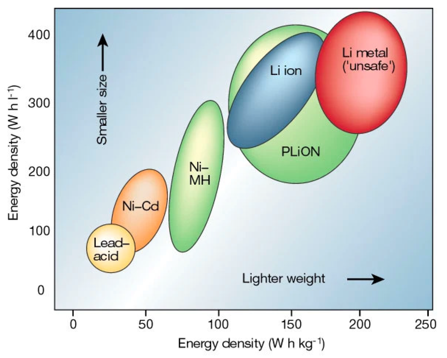
It is widely believed that the most efficient strategy to achieve meaningful reduction in greenhouse gas (GHG) emissions is by electrification of transportation and expanding the use of renewable energy sources. Both of these approaches require transformative energy storage technology [1,2,3,4,5,6]. One of the most promising energy storage technologies is solid-state lithium batteries (LBs) [7,8,9,10]. LBs are rechargeable, and they were first introduced on the market by Sony Corporation in 1991 [11]. One of the key distinctions of LBs is that they have a much higher energy density than conventional nickel-cadmium (Ni-Cd) [12], lead-acid (Pb-acid) [12], nickel-hydrogen (Ni-H2) [13], and silver-zinc (Ag-Zn) [14] batteries represented in a Ragone plot (Figure 1).
However, another safety issue common for conventional LBs is the high flammability and low thermal stability of organic liquid-state electrolytes [16,17,18,19]. This issue can be solved by substituting solid-state electrolytes (SSEs) in place of liquid-state electrolytes [20,21,22]. Solid oxide electrodes and electrolytes enable energy/power cells to operate at a higher temperature range and accelerate reactions at the cathode and anode, leading to a higher discharging/charging rate. In addition, SSEs have wider electrochemical windows that increase their adaptiveness to high-voltage cathode materials and lithium-metal anodes, which can also enhance the energy density (up to 70% [23]) and cycling performance of LBs. When combined with a lithium metal anode and Ni-rich oxide ceramic cathode, SSEs can enable the safest batteries with the highest energy density to meet the demand for electrification of air and surface transportation [24].
SSEs include polymer, inorganic (e.g., ceramic-based oxide electrolytes) and hybrid electrolytes. Free-standing polymer electrolytes could be prepared with proper crosslinkers [25,26,27,28,29] followed by photopolymerization as an in-situ approach [30,31,32,33,34]. Fabricated gel polymer electrolytes are capable of creating high-quality interfacial contact with electrodes and good electrochemical properties [35]. Besides, Li et al. [36] and Yao et al. [37] presented recently progress on polymer-based electrolytes. Unfortunately, they still have limited ionic conductivity at room temperature. Inorganic oxides SSEs mainly include perovskites, garnets, NASICON-type, and LISCON-type [38]. Cao et al. [38] comprehensively reviewed inorganic SSEs for lithium batteries. Similar to perovskites, hybrid polymer-ceramic systems utilize ceramic fillers with garnets as a dispersant into the polymer matrix (i.e., poly (ethylene oxide) (PEO)-based, polyacrylonitrile(PAN)-based, polyvinylidene fluoride (PVDF)-based, etc.) [39]. Goodenough et al. [40] fabricated low-cost hybrid PEO-LLZTO electrolytes and applied them in LiFePO4|Li cells that delivered high discharge capacity (139.1 mAh g−1 with capacity retention of 93.6% after 100 cycles). Falco et al., innovatively prepared cross-linked hybrid electrolytes to enhance ionic conductivity by mixing LLZO, lithium bis(trifluoromethanesulfonyl) imide (LiTFSI), tetra (ethylene glycol dimethyl ether) (G4) together under UV-light [41,42]. The hybrid electrolytes exhibited excellent ionic conductivity of 0.1 mS cm−1 at 20 °C. Passerini’s group [43] presented UV cross-linked PEO polymer electrolytes [44] with ionic liquids. The room temperature ionic conductivity could reach nearly 10−3 S cm−1.
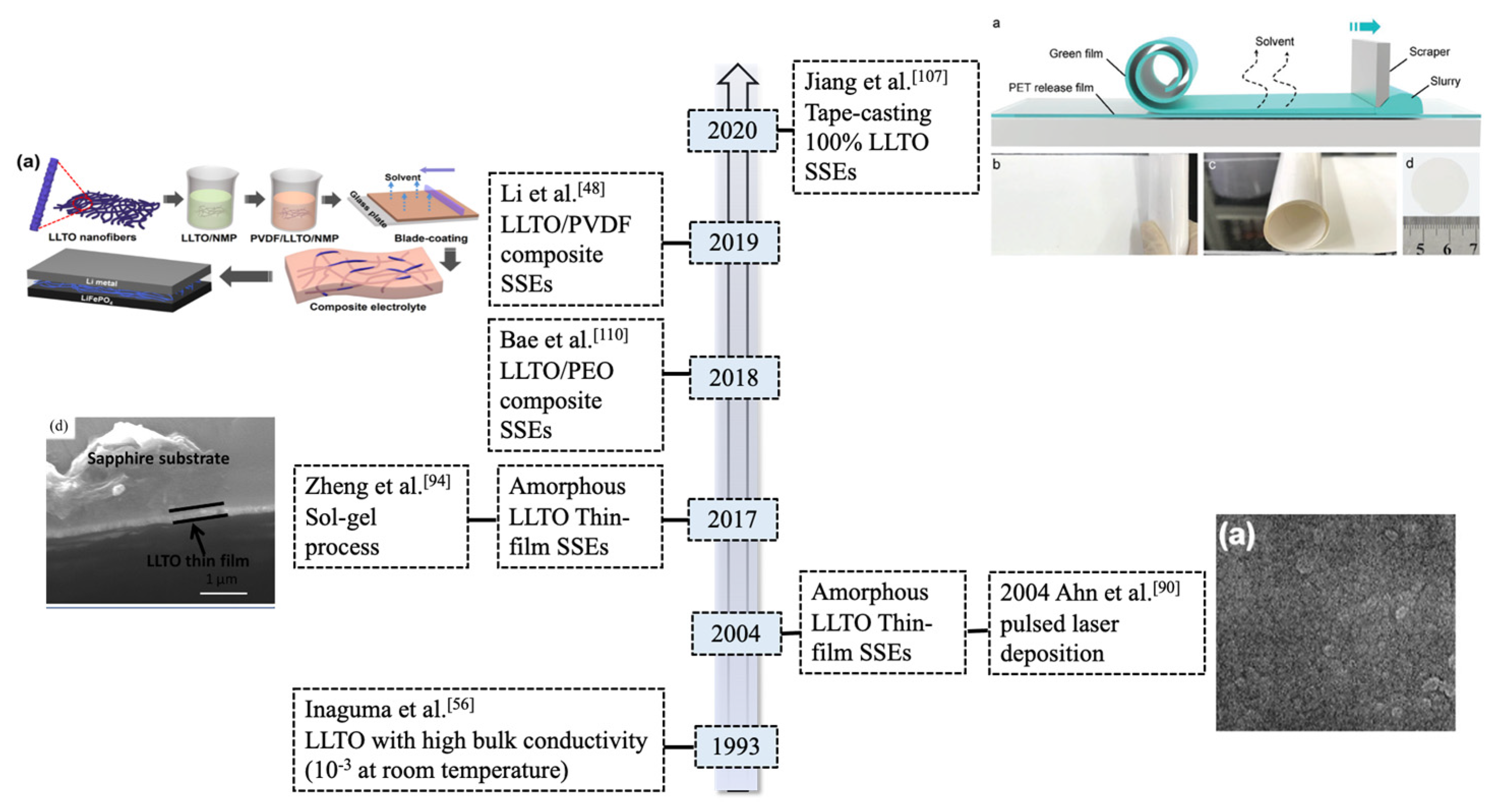
We summarized the progress of LLTO electrolytes in solid-state LBs (as shown in Figure 2). Many investigations have been undertaken on LLTO composite SSEs and electrochemical performance of selected electrolytes are summarized in the Table 1. However, hybrid electrolytes still suffer safety issues due to the flammability of the organic polymers. There is few research working on 100% ceramic electrolytes in solid-state LBs applications.
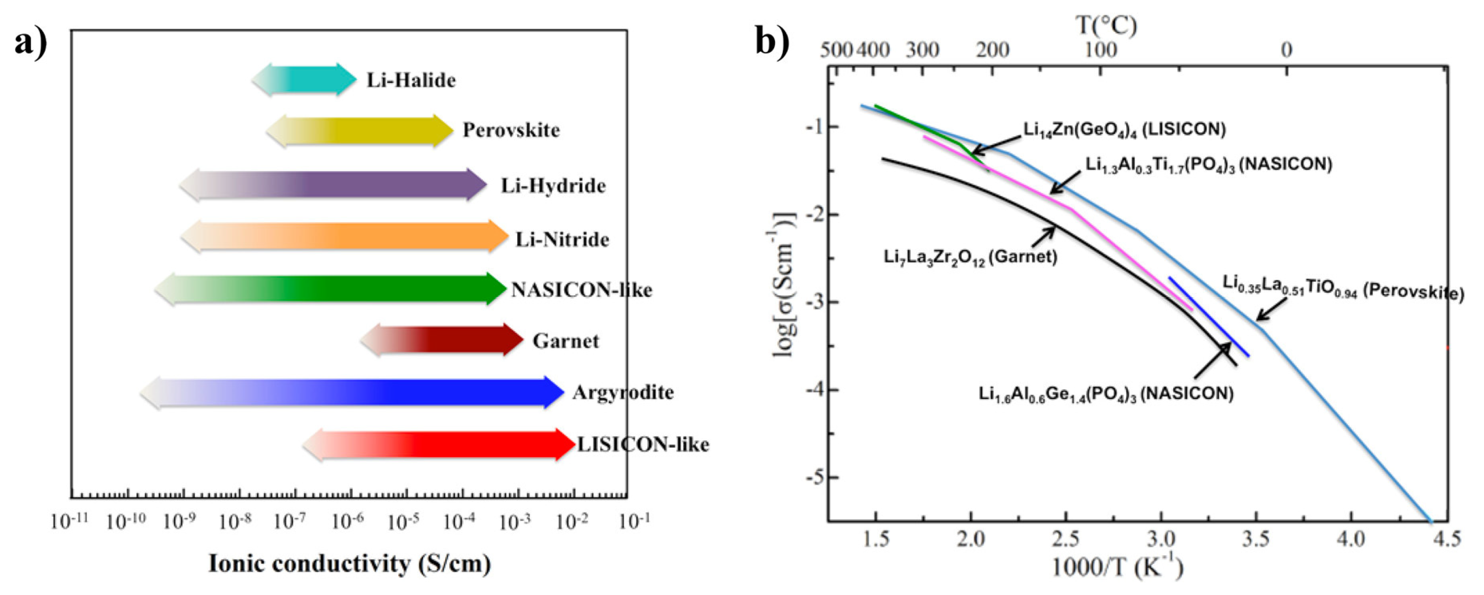
Perovskites usually demonstrate relatively high lithium-ion conductivities (10−3~10−4 S cm−1 at room temperature as shown in Figure 3a and low electronic conductivity [56] (i.e., 10−8 S cm−1). Inaguam et al. [57] was the first to report LLTO solid-state electrolytes (SSEs) with relatively high bulk ionic conductivity (i.e., 1 × 10⁻³ S cm−1 at room temperature) and total ionic conductivity (i.e., >2 × 10⁻⁵ S cm−1 at room temperature). Figure 3b shows the Arrhenius plots of the ionic conductivities of the perovskite compared with other ceramic SSEs. Thus, LLTO has been widely used as an additive within polymers to form composited electrolytes for ionic conductivities enhancement.
In general, LLTO has many advantages: (1) large ionic transference numbers (i.e., 0.5~0.9); (2) superior chemical and thermal stability in air; and (3) environmental friendless without any release of toxic gases during decomposition reactions. Besides, LLTO SSEs show wide electrochemical windows (8 V vs. Li/Li+) that increase their adaptiveness to high-voltage cathode materials and if combined with lithium-metal anodes. Also, LLTO exhibits excellent thermal stability (4–1600 K [58]) that provide potential applications even at extreme conditions.
However, there are several challenges that hamper the application of LLTO SSEs in batteries. First of all, the large grain boundary resistance reduces total ionic conductivity below 10−5 S cm−1 at room temperature [58]. Secondly, LLTO is chemically unstable when in direct contact with lithium metal. Lithium can be intercalated into LLTO at voltages below about 1.8 V, which causes the Ti4+ reduction and enhanced electronic conductivity [58]. Thirdly, the brittleness nature of LLTO makes it hard to fabricate and assemble into batteries. Besides, due to internal volume changes of batteries during operation, delamination of the ceramic oxide electrode and electrolyte layers can occur, causing the battery life to be shortened [59].
In this review, we presented and analyzed the origins of large grain boundary resistance for LLTO and solutions. We also gained an insight to the chemical instability of LLTO electrolytes when contacts lithium-metal anode. Moreover, we reviewed the tape-casting fabrication methods and electrochemical performances for 100% amorphous and crystalline LLTO SSEs in LBs.
2. Crystal Structure/Composition of LLTO and Relationship to Ionic Conductivity
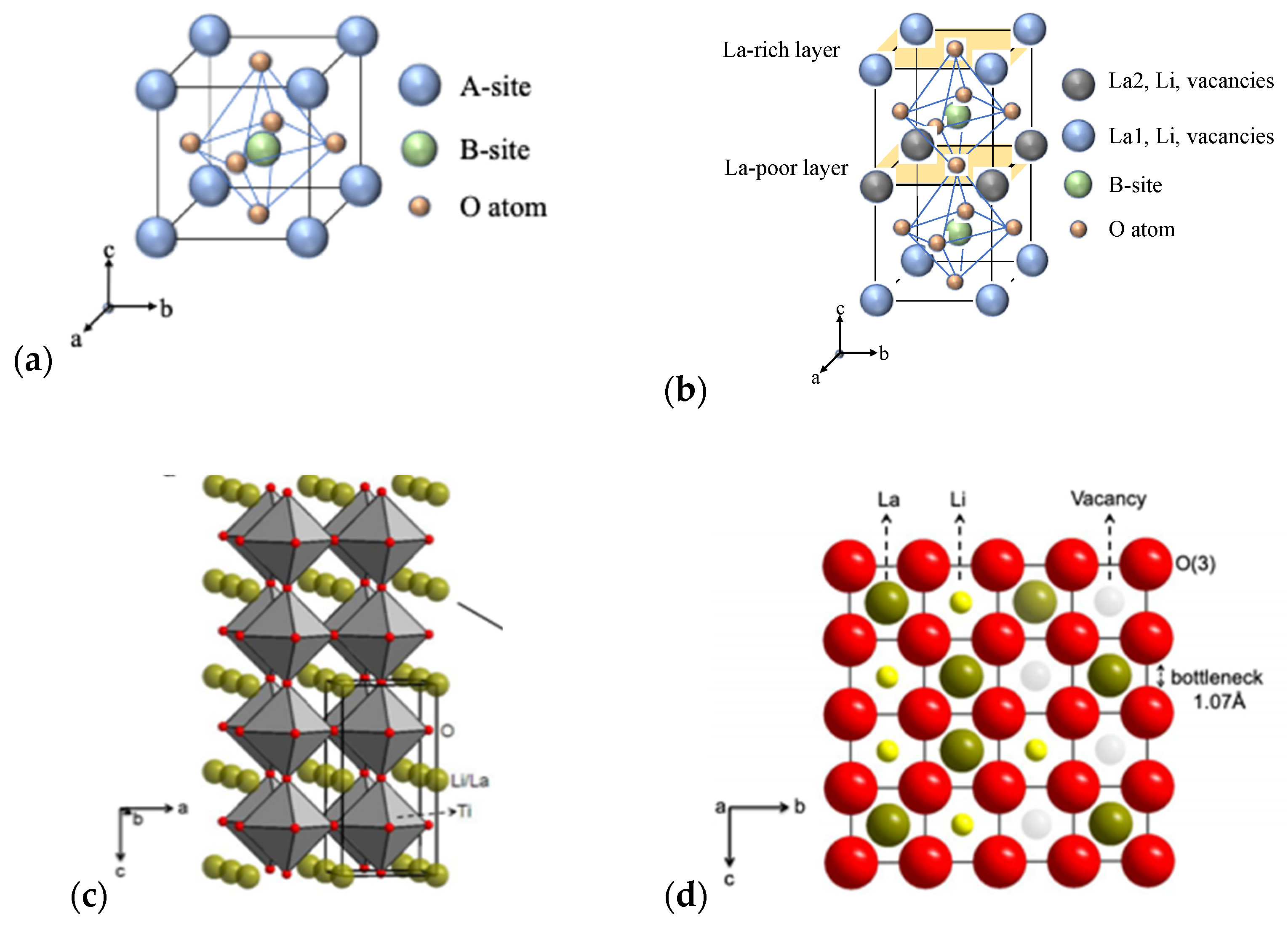
Perovskite La2/3−xLi3xTiO3 (LLTO)-family (0.04 < x < 0.16) with ABO3 structure (Figure 4a,b) has Li, La (La-rich and La-poor regions), and vacancies occupying the A sites, and Ti-ions occupying B sites that are octahedrally coordinated by oxygen [60].
Figure 4c indicates the crystal structure of the tetragonal-type perovskite with the lattice parameter of a = 3.8 Å [60] for cubic unit cell. Various x values of the lithium and lanthanum lead to distorted structures which generally originates from the unequal distribution of vacancies and displaced cations of Li+ and La3+. The bottleneck structure of perovskites consists of 12-fold coordinated with corner-shared oxygen as shown in Figure 4d [60]. The stable structure could be maintained when the x value is between 0.04 and 0.16.
Cubic and tetragonal LLTO (x ≈ 0.11) display a lattice structure with the stacking of La-rich and La-poor regions (Figure 4b) to maintain high bulk conductivity [60]. Inaguma and Itoh [61] showed that the conductivity of LLTO solid solution shows a parabolic dependence on x due to variations in the lithium to vacancy concentration and the formation of low activation energy pathways for ions controlled by site percolation and bottleneck size.
A lot of research has been dedicated to perovskite-type electrolytes to better understand the relationship of the chemical composition, crystal structure, and synthetic methods on lithium ionic conductivity [60,61]. Many works synthesized LLTO that the content of lithium around 0.11. Proper adjustments of this value depend on dopants in LLTO. Table 2 shows the summary of room-temperature ionic conductivities for selected LLTO SSEs (with common dopants) ionic conductivity at room temperature. The optimal x with the highest conductivity (more than 10−4 S cm−1 at room temperature) was found by many researchers to be around ~0.1 (LLTO commercial powder from TOHO TITANIUM CO., LTD).
3. Challenges and Potential Solution of Ceramic LLTO SSEs
3.1. Low Ionic Conudvtity of LLTO Electrolyte
Despite numerous attractive properties, the high grain boundary resistance of LLTO that leads to its low total ionic conductivity (2 × 10⁻⁵ S cm−1 at room temperature) [70], is a major challenge of incorporating LLTO SSEs in LBs. The total ionic conductivity is influenced by both grains and grain boundaries. Modifying the composition of grain boundaries is the dominant approach taken by researchers to increase total ionic conductivity for specific electrolytes. Another approach is to improve the density and reduce the grain size of LLTO, as explained in the following paragraphs.
Solutions to Improve Total Ionic Conductivity
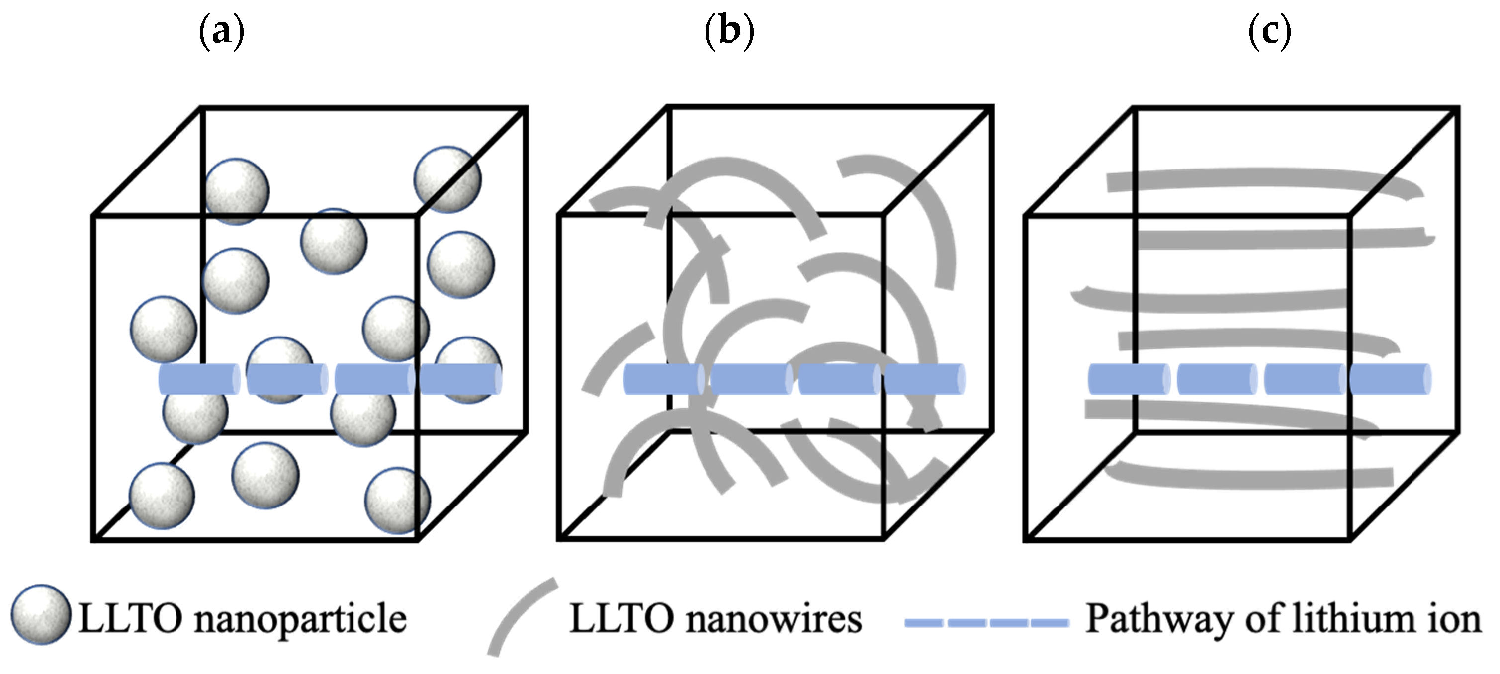
Morphology modification of LLTO (i.e., random or aligned one-dimensional (1D) LLTO nanofibers) is an effective way to improve its total ionic conductivity. Compared with LLTO particles, one dimensional LLTO nanofibers with high surface-to-volume ratios can increase the amount of continuous ion-conducting pathways [70,71,72]. Liu et al. [72] reported that 1D Li0.33La0.557TiO3 ceramic nanowire fillers can facilitate the formation of ionic conduction networks in the polyacrylonitrile-LiClO4 matrix to enhance their total ionic conductivity of the resulting SSEs by three orders of magnitude than using nanoparticles (2.4 × 10⁻⁴ S cm−1 at room temperature). Figure 5 shows the difference between lithium-ion pathways when using LLTO nanoparticles and nanofibers (i.e., random or aligned) [72]. Compared with isolated nanoparticles in Figure 5a, random nanowires could supply continuous fast pathways for Li-ion transportation. While compared with random nanowires in Figure 5b, well aligned nanowires in Figure 5c are free of crossing junction. The ionic conductivity for well aligned LLTO SSEs is 6.05 × 10⁻⁵ S cm−1 at 30 °C, which is one order magnitude higher than SSEs with randomly aligned nanowires [72].
3.2. Large Grain Boundary Resistance of LLTO
Grain boundary resistance is generated at the interface between crystallites in LLTO matrices and can hinder the pathway of lithium-ion migration, thus limiting grain boundary conductivity. Lattice mismatch refers to the mismatch between LLTO grain boundaries that is composed of a Ti-O binary compound with a 2–3 unit-cell thickness. Lattice mismatch appears when most grain boundaries between LLTO matrices tend to comprise structural and chemical deviations for compensation of random orientation of neighboring LLTO grains [73]. It is not energetically favorable for either lithium-ion accommodation or migration, resulting in poor grain boundary conductivity [73].
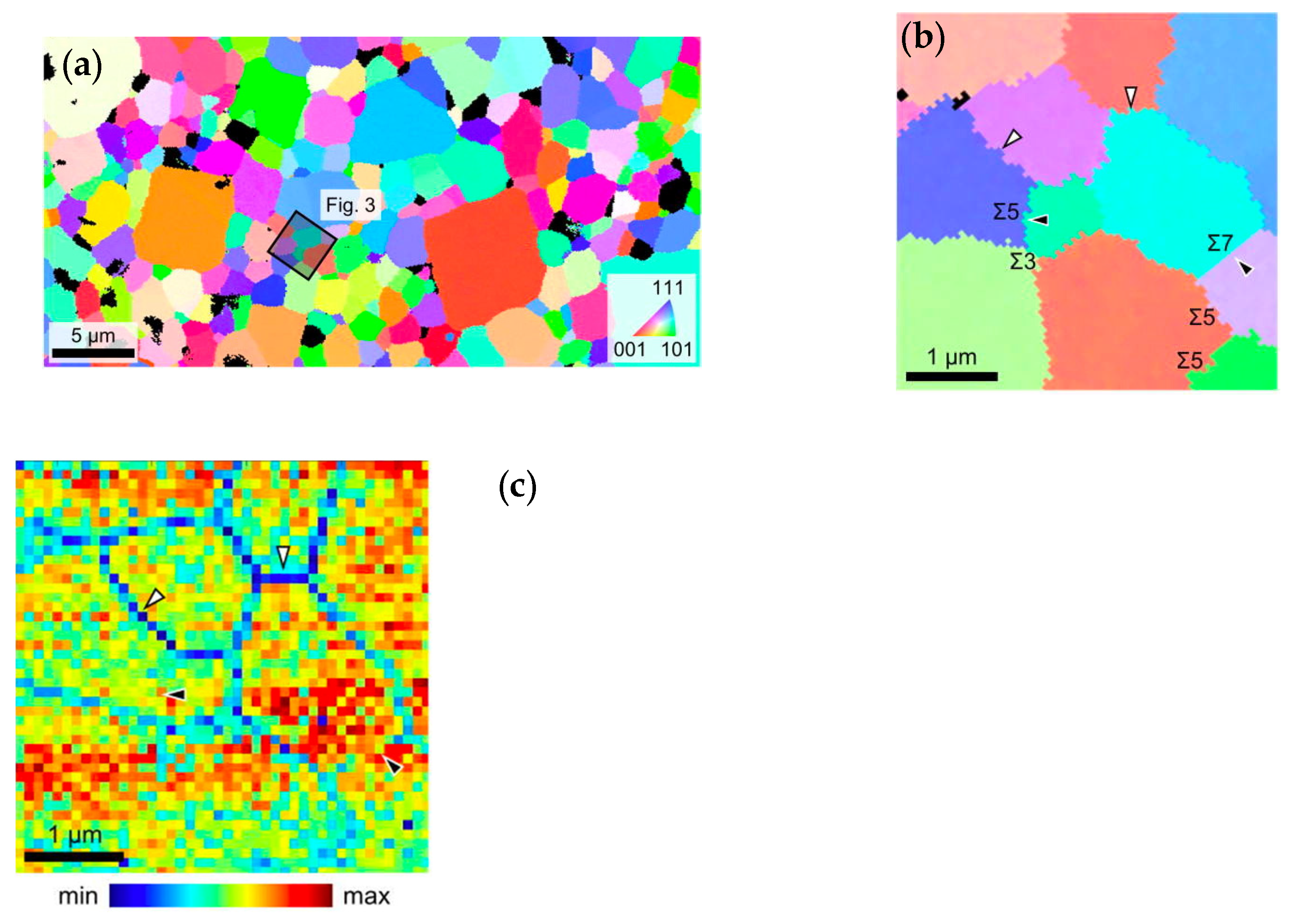
Sasano et al. [74] proposed that the grain boundary conductivity can be significantly enhanced by increasing the number of coincidence-site lattices (CSL) at the grain boundaries. For the geometric CSL of the grain boundary, the index is used and the smaller value, the higher lattice coincidence grain boundaries. When values are larger than , the grain boundaries are considered as random. SEM-EBSD crystallographic orientation map and ESM loop area map measured at the same region (the black square as shown in Figure 6a). The higher ESM signal intensity corresponds to the higher Li-ion conductivity (grain boundary of black arrowheads as shown in Figure 6b,c). CSL at the grain boundaries are relatively regular than random regions, which have fewer composition deviations and structural distortions. These results suggested that control geometries of the grain boundaries for the improvement of the Li-ion conductivity in LLTO.
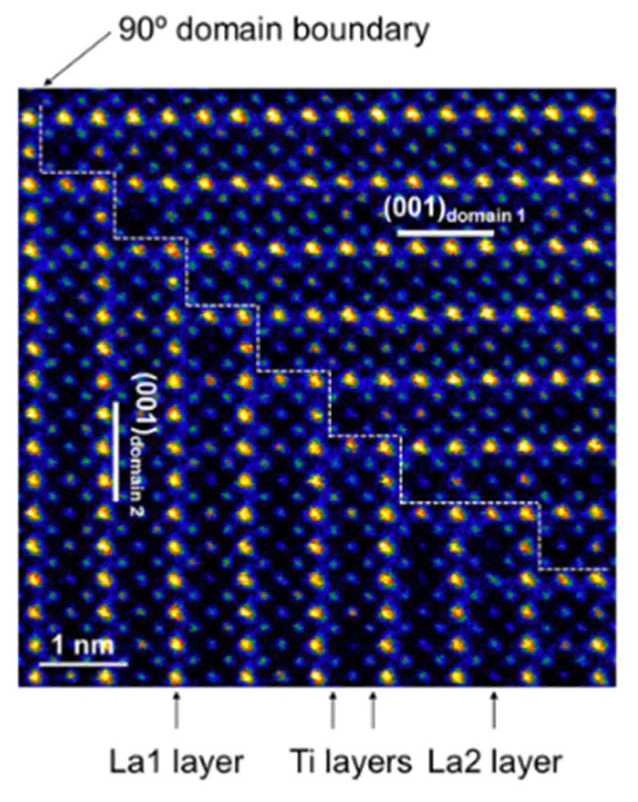
Another contributing factor to grain boundary resistance is the 90° domain boundary that exists between neighboring La-rich regions [75] as shown in the Figure 7. Moriwake et al. pointed out that when lithium ions migrate through La-rich layers, an extremely high activation energy (Ea = 3.58 eV) in the 90° grain boundaries significantly blocks the pathways of lithium ions and limits their diffusion [75,76].
3.2.1. Solutions to Reduce the Grain Boundary Resistance
As mentioned previously, modifying the LLTO grain boundary composition would be an effective way to reduce the grain boundary resistance. One successful approach is to introduce dopant elements into the A-sites and/or B-sites in the crystalline structure of LLTO via the formation of more point defects. Another way is to introduce an amorphous layer or valence ions (e.g., Ag+ ions [65]) into LLTO grain boundaries. Mei et al. [77] introduced an amorphous glassy silica layer into LLTO grain boundaries that reduced the grain boundary resistance and further enhanced the total ionic conductivity (>1 × 10⁻⁴ S cm−1 at room temperature).
3.2.2. Solutions to Enhance Grain Conductivity
To increase grain conductivity, researchers have used hot-pressing techniques, particularly spark plasma sintering (SPS) to make LLTO SSEs with higher density and lower porosity [78,79]. Compared to conventional hot-pressing, SPS can achieve higher heating rates (up to 600 °C min−1) and densities, at much lower times (0–10 min in most cases). Luo et al. [80] fabricated perovskite-type Li3/8Sr7/16Ta3/4Zr1/4O3 (LSTZ) SSEs via hot-pressing and the obtained LSTZ pellets showed an increased density (i.e., relative density of 96.7%), enhanced total ionic conductivity (i.e., 4.1 × 10⁻⁴ at 25 °C), and improved compressive strength due to fewer pores and better grain contact. Mei et al. [81] prepared LLTO SSEs by SPS that yielded highly dense (i.e., a relative density of over 97%), fine-grained (i.e., a grain size of 2 μm) LLTO ceramics, with an increased total ionic conductivity (>10−3 S cm−1 at room temperature).
3.3. Chemical Stability of LLTO Electrolyte against Lithium Metal
3.3.1. Ti Reduction at the Interface
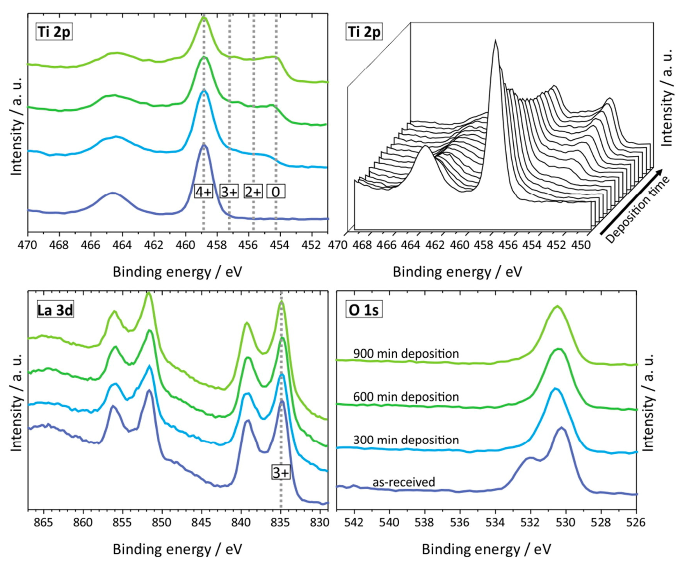
LLTO reacts readily with lithium metal and changes color from white (pristine) to deep black due to the ease of reduction of Ti4+ cation to lower oxidation state Ti3+ specie as evidenced by X-ray photoelectron spectroscopy (XPS) studies [82]. This also accompanied with the formation of oxygen vacancies which in turn makes the interface very conductive electronically and not suitable as an electrolyte for lithium metal battery [82]. Liu et al. [82] confirmed that black LLTO showed two new peaks at the lower binding energies corresponding to the formation of Ti3+ with lower electron densities. Galvez-Aranda et al. [83] identified that Ti reduction occurs at the LLTO/Li metal interface. The reaction rate at the interface increases as the applied external electric field increases corresponding to an electrochemical instability of the LLTO/Li-metal interface. S Wenzel et al. [84] further investigated the reaction of LLTO with lithium metal (i.e., by lithium insertion) by in situ XPS system. Detailed spectra for the Ti 2p, La 3d and O 1s of LLTO is shown in Figure 8. The lithiation process clearly impacts the reduction of Ti 2p. Figure 9 shows the color change from white to black for LLTO electrolyte. The increased deposition times have no effect on La 3d and all specific peaks remain unchanged. XPS results for Ti 2p plot indicate the fits for the four Ti oxidation states (Ti4+, Ti3+, Ti2+ and Ti0). Ti4+ can be greatly reduced to metallic titanium Ti0 when depositing time is 300 min. The formation of metallic Ti would cause the higher electronic conductivity of LLTO.
However, there are few articles that mention how to overcome this problem for LLTO electrolytes. PVDF-b-PTFE polymer matrix was mixed with LLZO and LLTO nanofibers (PPLL) [82] to ensure a gapless solid interfacial contact against Li-metal anode and decreased Ti4+ reduction. The assembled battery of LFP|PPLL|Li delivered a high initial discharge capacity of 150 mAh g−1 and retained 127 mAh g−1 over 550 cycles. The coulombic efficiency was always more than 99.5% during cycling.
Most works coincidentally use the metal-layer coating (i.e., Au, Ag, and Cu) for the conductivity measurements as an interfacial layer in symmetric cells to protect LLTO from reacting with a lithium-metal anode. One approach that worked successfully with garnet-type electrolytes which the most popular of which is to use an interfacial layer that have greater stability (kinetic or by the formation of stable SEI such as PEO-based electrolyte films. One direction is to use metal oxides. Wang et al. [85] coated an ultrathin ZnO layer onto garnet solid-state electrolytes that significantly decreases the interface resistance to as low as about 20 Ω cm−2. Han et al. [86] used Al2O3 by atomic layer deposition on a garnet electrolyte that the interfacial impedance was reduced to 1 Ω cm−2. Another direction is to induce alloying reaction between the Li metal and metal layer. Luo et al. deposited a 20 nm germanium (Ge) on garnet electrolyte. Fu et al. [87] alternatively applied Al metal coating and could reduce the interface resistance by more than an order of magnitude.
3.3.2. Formation of Lithium-Oxide and Lanthanum-Oxide Phase at the Interface
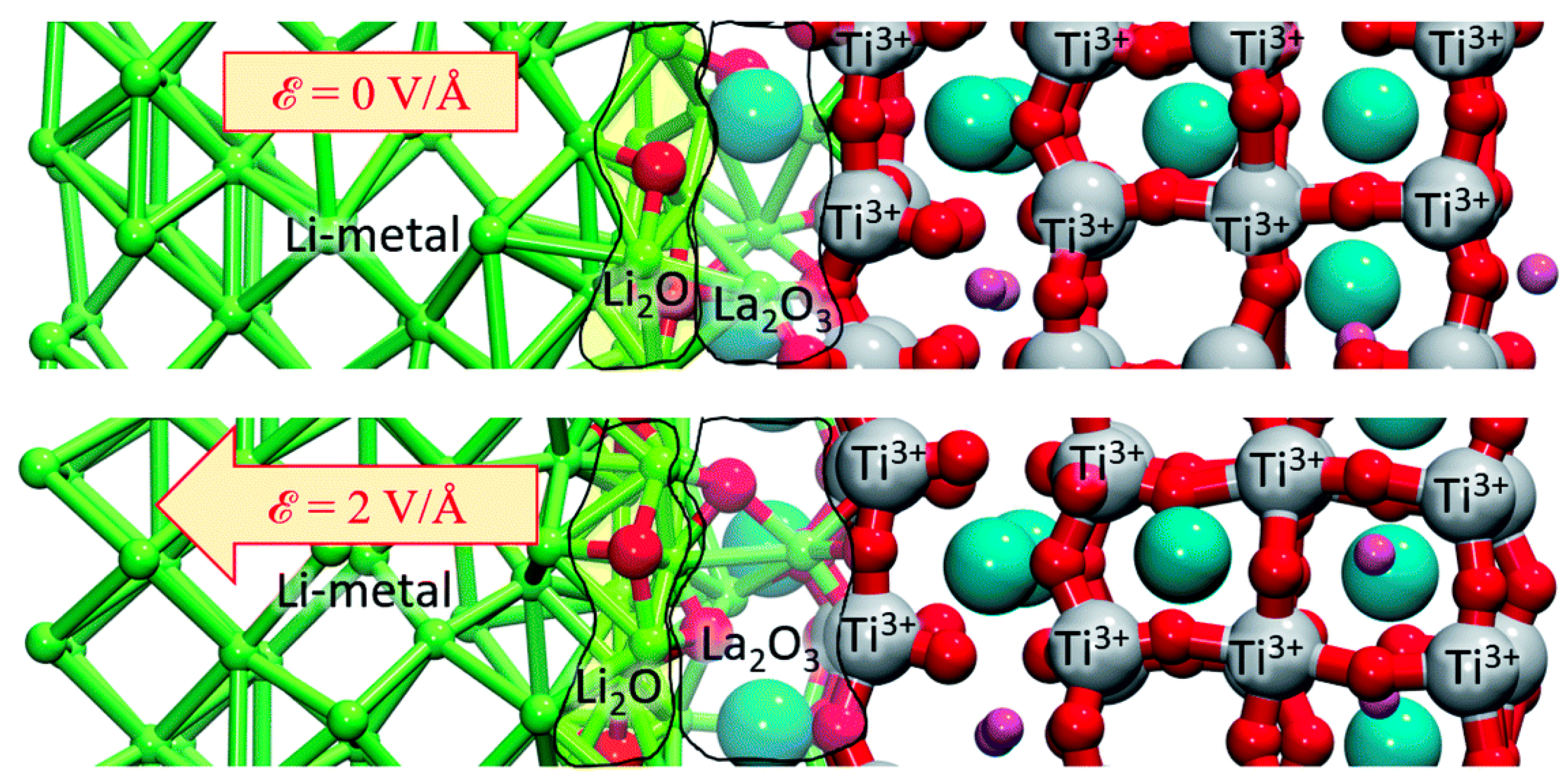
Galvez-Aranda et al. [83] used an ab initio molecular dynamics study to propose that lithium-oxide and lanthanum-oxide phases are formed when LLTO is in contact with Li metal. The main reactions at the interface lead to the formation of Li-O and La-O. O comes from the TiO3 structure of LLTO crystal and breaks the original Ti-O bonds. Besides, presence of La at the interphase helps break the Ti–O bonds and create more Li–O bonds. Thus, the formation of lithium-oxide is always faster than the lanthanum-oxide. From a mean square displacement (MSD) analysis, the oxygen atoms migrate at the constant positive rate and keep being displaced toward the Li-metal anode. When applying an external electric field, the formation of both oxides is accelerated as shown in Figure 10.
3.4. Fabrication of LLTO into Thin Films
3.4.1. Amorphous LLTO Thin Films
Amorphous thin-film of LLTO SSEs have an open and disordered structure and can be prepared using a chemical solution method, like the sol-gel process [88], or physical vapour deposition techniques, such as radio frequency (RF) magnetron sputtering, pulsed laser deposition (PLD), electron-beam (e-beam) evaporation, and spin coating [63].
LLTO thin films prepared by RF magnetron sputtering and PLD can transform amorphous LLTO into a crystalline phase [89,90,91]. Xiong et al. [89] deposited LLTO thin films by RF magnetron sputtering and results showed that LLTO thin films were amorphous at annealing temperatures below 400 °C; while crystalline phase appeared when annealing temperature was higher than 400 °C.
Fabricating thin-film LBs with a pure LLTO matrix only would be an effective way to enhance ionic conductivity. Thin-film LBs with LLTO matrices have large active surface areas and reduced volumes, which increases the charge rates via decreased diffusion lengths of lithium-ions. However, thin-film electrolytes of crystalline-phase LLTO matrices have significant grain boundary resistances and are unstable when in contact with lithium metal due to the reduction reaction of Ti4+ to Ti3+ [92]. Thus, adjusting the orientation of LLTO grains, or directly replacing the crystalline phase of LLTO with an amorphous one, were found to be effective modifications that resolve these issues and enhance the total ionic conductivity of the SSEs.
Epitaxial growth of LLTO thin films on single crystal substrates prepared by e-beam evaporation results in uniform LLTO grains without obvious pinholes or cracks [93]. The orientational growth of LLTO thin films significantly affects the size of the LLTO lattices. For example, the growth of these films on the (100) and (111) oriented SrTiO3 (STO) substrates reduced lattice and thermal strains in the LLTO films, which is expected to further improve the total ionic conductivity and stability [94].
3.4.2. Tape-Casting LLTO Films
Physical vapour deposition methods mentioned above are able to deposit thin layers but are often expensive or limited in their scalability [95]. The cold-pressed pellets are still fragile; and the thickness limitations of the cold-pressed pellets are around 200 μm [96,97]. This problem could be addressed by implementing the tape casting technology to cast thin and suitable electrolytes of LLTO. Tape casting is increasingly popular as it is compatible with current manufacturing processes of lithium batteries hence lower capital cost and easier penetration into the market.
LLTO is brittle and thus proper fabrication methods are essential to make high-quality ceramic SSEs with good mechanical strength. Tape casting technology which consists of casting slurry on a carrier film, has been effectively used for mass production of thin-film solid-state electrolytes and layered ceramic structures. The slurry consists of powdered ceramics, binders, plasticizers, and dispersants. The tape is formed by moving the doctor blade with a certain height [98] over the poured slurry and the height of the blade determining the thickness of the green tape. After the drying, the thickness of tapes could shrink to less than 100 μm which will be followed by sintering to enhance the densification [99,100].
A high-quality cast tape should satisfy some criteria [99,100,101], such as (1) no agglomeration and cracks during drying; (2) microstructural homogeneity; (3) free-standing from carrier film after drying; and (4) good lamination ability and mechanical strength after sintering. Thus, several rules need be considered to prepare satisfying pellets: (1) viscosity control of the slurry by changing the ratio among ceramics, binder, plasticizer, dispersant, and solvent; (2) drying condition adjustment to obtain flat and homogeneous green tape; and (3) sintering temperature and duration set-up for binder removal and final pellets densification. Table 3 summarizes green tape preparations and casting parameters. A ball mill is normally used in the casting process to obtain homogeneous slurry. Laminations by several layers of green tapes before sintering is effective to enhance mechanical strength and packing integrity.
Reports of fabricating LLTO electrolytes using tape casting technology are scarce. Some have reported on how to optimize the slurry composition by adjusting various parameters including dispersant concentration, ratio of binder to plasticizer, total amount of binder and plasticizer, and drying conditions. Schrökert et al. [102] found that a dispersant concentration of 2 wt.% was sufficient to obtain homogenous suspension of slurry. The binder-plasticizer ratio was set to 2:1 and the slurry with a total amount of binder and plasticizer of 15 wt.% yielded high-quality tapes. In addition, fast drying was proven to be beneficial for preparation of the best tapes.
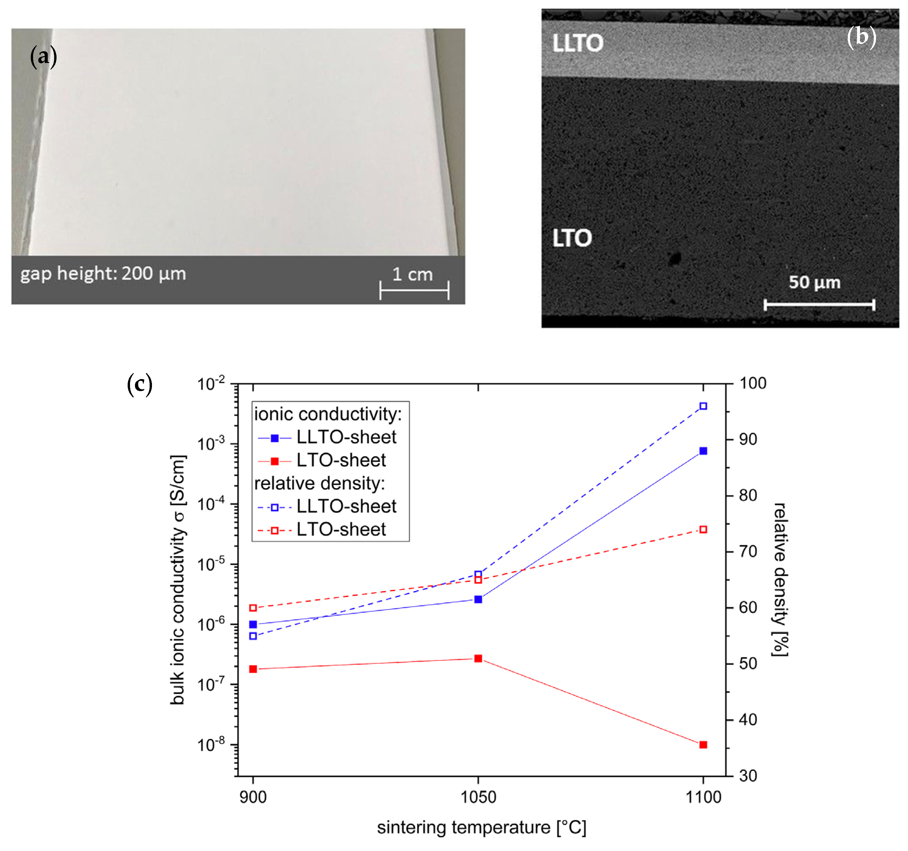
Others aim to increase ionic conductivity of tape-cast LLTO films. Jiménez et al. [103] prepared LLTO thick films (sintered at 1100 °C) with bulk conductivity of 1.7 × 10⁻⁵ S cm−1 at 300 K. However, incomplete reincorporation of lithium results in less-conducting grain boundary, which decreased dramatically the total lithium conductivity (5 × 10⁻⁸ S cm−1 at 300 K). Schiffmann et al. [104] casted LLTO pellets and then assembled it with LTO anode into half-cell by co-sintering as shown in Figure 11a,b. LLTO tapes with the thickness of about 25 μm maximizes the ionic conductivity close to 10−3 S cm−1 at sintering temperature of 1100 °C (as shown in Figure 11c). Employing a lamination process ensures the formation of close and homogeneous interface between LLTO and LTO during co-sintering.
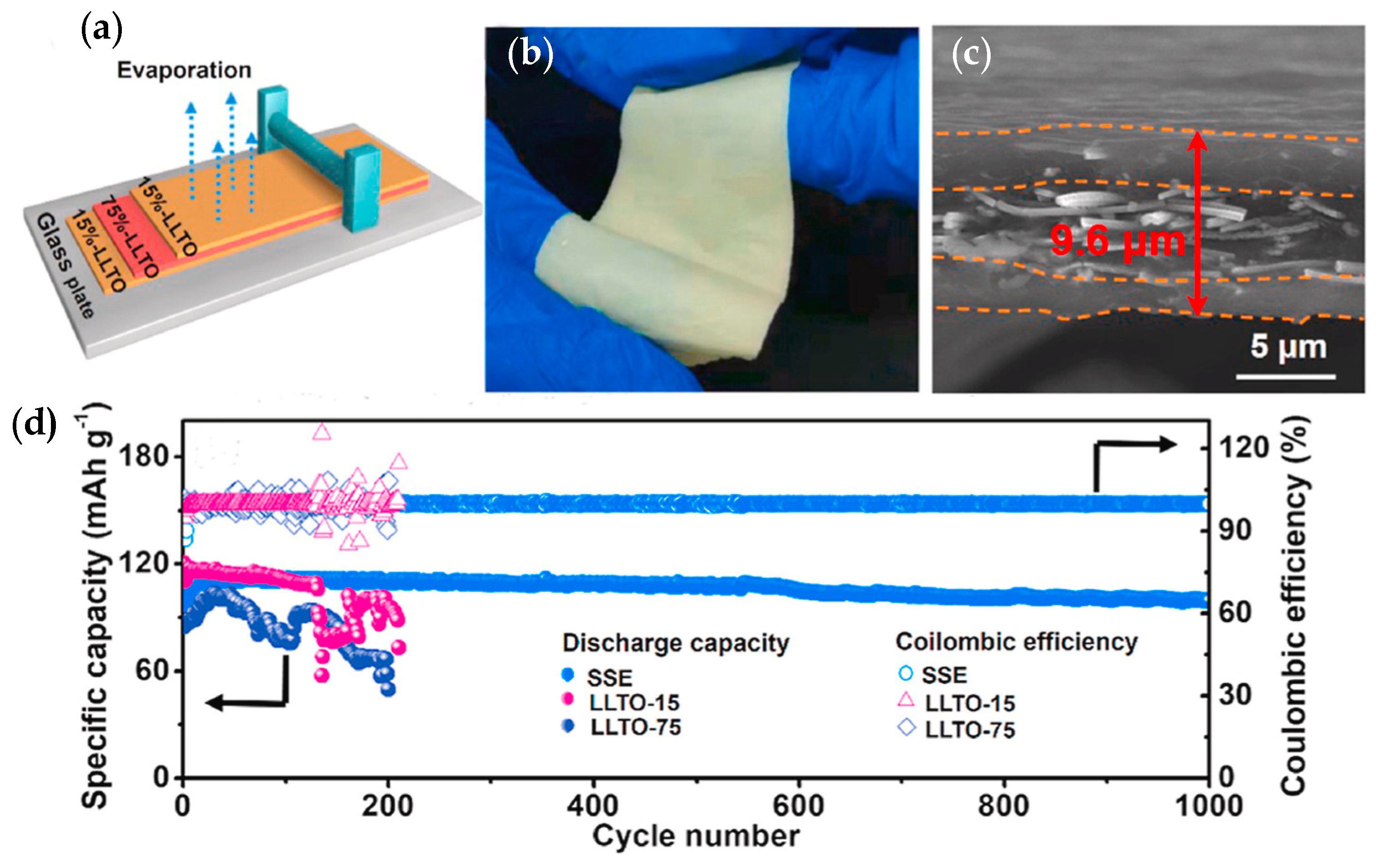
In order to enhance ionic conductivity, polymers and oxides are employed to form composite or hybrid electrolytes. Zhang et al. [105] employed tape casting and calcination to fabricate LLTO|Al2O3 composite electrolytes (details as shown in Figure 12). The new phase of LiAl2O8 could reduce Li2O loss from the composites and extend the junction between LLTO grains. LLTO|10 wt.% Al2O3 exhibits higher bulk (9.33 × 10⁻⁴ S cm−1) and grain boundary conductivity (2.38 × 10⁻⁵ S cm−1) at room temperature, which were enhanced around six times and three times compared to pure LLTO. Li et al. [106] fabricated ultrathin 75% LLTO|PVDF (LLTO-75) with a thickness of 7.5 μm with a high ionic conductivity (4.7 × 10⁻⁴ S cm−1 at room temperature). The LLTO-75 membrane was used as intermediate layer and sandwiched by two 15% LLTO/PVDF (LLTO-15) membranes. Symmetric Li|sandwiched SSE|Li maintains a low voltage gap of 98 mV for 450 h at 1 mA cm−2. Li|LFP achieves a specific capacity of 108 mA h g−1 at 1C with a high-capacity retention of 91.8% after 1000 cycles.
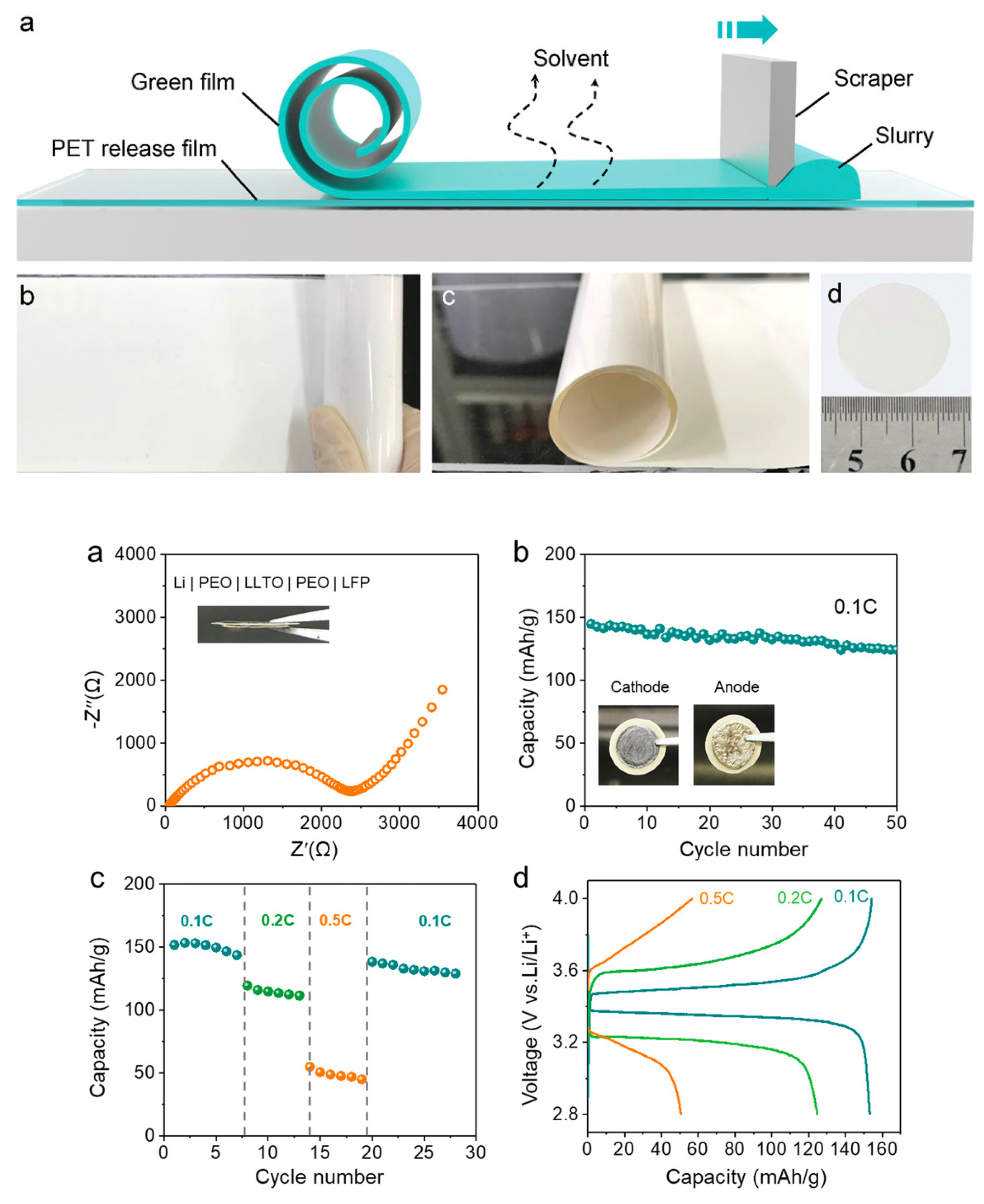
Jiang et al. [107] fabricated tape-cast ceramic LLTO film with a reduced thickness of 25 μm. Figure 13 shows fabrication for tape-casting methods and related battery performance. The total Li ionic conductivity was improved to 2.0 × 10⁻⁵ S cm−1 compared to a thick electrolyte (>200 μm) prepared by cold-pressing. Symmetric Li|PEO|LLTO-41 (41 μm is the thickness of LLTO pellet) | PEO |Li cell was assembled to obtain the Nyquist plot. The aid of PEO electrolyte coating could avoid reduction of Ti element and alleviate contact between Li metal and electrolyte. In this way, the total resistance of a symmetrical cell was reduced to about 2250 Ω. Galvanostatic stripping and plating was performed on a symmetrical Li cell to evaluate the long-term interface stability. After 20 cycles, the original overpotential of 67 mV at 0.025 mA cm−2 was reduced to a relatively stable value of 26 mV. The average overpotential increased to 100 mV at 0.1 mA cm−2. The stable overpotential remained to 54 mV at 0.05 mA cm−2. Li|LFP full cell was successfully assembled and exhibited good battery performance. The initial discharge capacity was 145 mAh g−1 at current density of 0.1C and a capacity retention of 86.2% after 50 cycles.
4. Conclusions
Solid-state lithium batteries (LMBs) can provide enhanced safety and a higher energy density compared to liquid-based lithium-ion batteries (LIBs). In particular, ceramic-based oxide electrolytes (e.g., LLTO) with high ionic conductivity, excellent oxidative electrochemical stability, and superior thermal stability are currently considered as potential solid-state electrolytes for the fabrication of SSBs to enable their commercialization.
However, LLTO still has many challenges to overcome at many levels including the material design and synthesis with the required properties, processing level and battery performance.
Challenge 1: at the material level: LLTO suffers from high grain boundary resistance that leads to limited ionic conductivity of polycrystalline ceramic-based oxide SSEs. Several strategies have been adopted to overcome the issue such as microstructural engineering of grains or introducing amorphous phase into grain boundary directly which was found to decrease resistance and thus enhance total conductivity. Other strategies include fabrication of amorphous and single-crystal LLTO films.
Also, many approaches have been followed to improve total ionic conductivities:
- Doping: dopants such as Sr, Y, Nb, etc. could modify the crystal structure of LLTO and enhance the ionic conductivity in excess of 10−4 S cm−1 at room temperature.
- Nano-structuring: we have shown that there is enough support to the idea that implementing well aligned 1D LLTO materials in nanoscale morphology can enhance ionic conductivity by effectively facilitating lithium-ion migration and reducing grain boundary resistance. From this idea, fabricating 3D vertically aligned channels within 100% ceramic electrolytes may be effective to maintain high ionic conductivity with no presence of flammable polymeric components as matrix.
Challenge 2: processing and fabrication of all-ceramic LMBs: Fabrication of all-ceramic LMBs might be a potential solution to eliminate safety hazards for LMBs.
- Tape casting technology is very compatible with existing roll-to-roll battery manufacturing processes and a lot of research is focused on its use in SSBs to make thin films (<100 μm). Optimization of slurry recipe and sintering conditions is essential to obtain good quality of final tapes. It is still challenging to fabricate large-scale tape-casting films for solid-state LMBs.
- Li loss during sintering: thin films always need to be sintered at high temperature to be further densified, while Li evaporates apparently over 900 °C. To counteract the undesired Li loss in pellets, researchers typically surround green tapes with the mother powder during sintering to reduce any further Li losses from electrolytes, but Li sublimation still occurs. Introducing low melting point phases (also called sintering aids) could be acceptable for processing electrolyte with improved sinterability and density [108,109].
Challenge 3: capability of lithium metal and battery performance. Battery assembly and manufacturing based on ceramic SSEs is another important consideration for high energy density LMBs. The following issues still need to be addressed:
- Compatibility with Li metal: the poor contact between Li metal and LLTO SSEs. Li metal reacts easily with Ti4+ cation inside LLTO. Thus, it is essential to modify the surface of LLTO SSEs. Some researchers employed protective layers including metal or metal oxides or polymers for garnet-type (i.e., LLZO) SSEs. Moreover, the addition of liquid electrolyte [87] could be one compromising way to reduce interfacial resistance.
- Mechanical strength and stacking pressure: the brittleness of LLTO ceramic thin films makes battery assembly very challenging. Appropriate a stacking pressure needs to be applied that could maintain good contacts among layers but cause no damage to SSEs. Buffer layers such as nickel-coated sponge [107] may be effective to prevent SSEs from crack and fracture.
Finally, LLTO is a promising solid-state electrolyte material with potential use in solid state batteries. However, like all other candidate materials (other oxides, phosphates, sulphides, or halides), it suffers from many drawbacks that currently hamper their commercialization into SSBs. Nevertheless, intensive research into innovative strategies to overcome these challenges can lead to its adoption in high-energy LMBs.
Author Contributions
Writing-original draft & editing, S.Y., writing-review & editing, C.-H.Y., V.P., M.B., E.B., A.W., A.M., Y.A.-L. All authors have read and agreed to the published version of the manuscript.
Funding
This research was funded by National Research Council Canada, A1-026222-20-01.
Institutional Review Board Statement
Not applicable.
Informed Consent Statement
Not applicable.
Data Availability Statement
Not applicable.
Acknowledgments
The authors gratefully acknowledge financial support from the National Research Council of Canada (NRC) under the Low Emission Aviation Program (LEAP).
Conflicts of Interest
The authors declare no conflict of interest. The funders had no role in the design of the study; in the collection, analyses, or interpretation of data; in the writing of the manuscript, or in the decision to publish the results.
References
- Denholm, P.; Kulcinski, G.L. Life cycle energy requirements and greenhouse gas emissions from large scale energy storage systems. Energy Convers. Manag. 2004, 45, 2153–2172. [Google Scholar] [CrossRef]
- Goodenough, J.B.; Kim, Y. Challenges for Rechargeable Li Batteries. Chem. Mater. 2010, 22, 587–603. [Google Scholar] [CrossRef]
- Goodenough, J.B.; Park, K.-S. The Li-Ion Rechargeable Battery: A Perspective. J. Am. Chem. Soc. 2013, 135, 1167–1176. [Google Scholar] [CrossRef]
- Larcher, D.; Tarascon, J.-M. Towards greener and more sustainable batteries for electrical energy storage. Nat. Chem. 2015, 7, 19–29. [Google Scholar] [CrossRef]
- Liang, Y.; Su, J.; Xi, B.; Yu, Y.; Ji, D.; Sun, Y.; Cui, C.; Zhu, J. Life cycle assessment of lithium-ion batteries for greenhouse gas emissions. Resour. Conserv. Recycl. 2017, 117, 285–293. [Google Scholar] [CrossRef]
- Liu, J.; Bao, Z.; Cui, Y.; Dufek, E.J.; Goodenough, J.B.; Khalifah, P.; Li, Q.; Liaw, B.Y.; Liu, P.; Manthiram, A.; et al. Pathways for practical high-energy long-cycling lithium metal batteries. Nat. Energy 2019, 4, 180–186. [Google Scholar] [CrossRef]
- Dehghani-Sanij, A.R.; Tharumalingam, E.; Dusseault, M.B.; Fraser, R. Study of energy storage systems and environmental challenges of batteries. Renew. Sustain. Energy Rev. 2019, 104, 192–208. [Google Scholar] [CrossRef]
- Yang, Z.; Zhang, J.; Kintner-Meyer, M.C.; Lu, X.; Choi, D.; Lemmon, J.P.; Liu, J. Electrochemical Energy Storage for Green Grid. Chem. Rev. 2011, 111, 3577–3613. [Google Scholar] [CrossRef] [PubMed]
- Ciez, R.E.; Whitacre, J.F. Examining different recycling processes for lithium-ion batteries. Nat. Sustain. 2019, 2, 148–156. [Google Scholar] [CrossRef]
- Ellingsen, L.A.-W.; Hung, C.R.; Strømman, A.H. Identifying key assumptions and differences in life cycle assessment studies of lithium-ion traction batteries with focus on greenhouse gas emissions. Transp. Res. Part D Transp. Environ. 2017, 55, 82–90. [Google Scholar] [CrossRef]
- Nishi, Y. Lithium ion secondary batteries; past 10 years and the future. J. Power Sources 2001, 100, 101–106. [Google Scholar] [CrossRef]
- Tariq, M.; Maswood, A.I.; Gajanayake, C.J.; Gupta, A.K. Aircraft batteries: Current trend towards more electric aircraft. IET Electr. Syst. Transp. 2017, 7, 93–103. [Google Scholar] [CrossRef]
- Lee, J.-W.; Anguchamy, Y.K.; Popov, B.N. Simulation of charge–discharge cycling of lithium-ion batteries under low-earth-orbit conditions. J. Power Sources 2006, 162, 1395–1400. [Google Scholar] [CrossRef]
- Ratnakumar, B.V.; Smart, M.C.; Kindler, A.; Frank, H.; Ewell, R.; Surampudi, S. Lithium batteries for aerospace applications: 2003 Mars Exploration Rover. J. Power Sources 2003, 119, 906–910. [Google Scholar] [CrossRef]
- Miao, Y.; Hynan, P.; Von Jouanne, A.; Yokochi, A. Current Li-Ion Battery Technologies in Electric Vehicles and Opportunities for Advancements. Energies 2019, 12, 1074. [Google Scholar] [CrossRef] [Green Version]
- Scrosati, B.; Garche, J. Lithium batteries: Status, prospects and future. J. Power Sources 2010, 195, 2419–2430. [Google Scholar] [CrossRef]
- Quartarone, E.; Mustarelli, P. Electrolytes for solid-state lithium rechargeable batteries: Recent advances and perspectives. Chem. Soc. Rev. 2011, 40, 2525–2540. [Google Scholar] [CrossRef] [PubMed]
- Chen, S.; Wen, K.; Fan, J.; Bando, Y.; Golberg, D. Progress and future prospects of high-voltage and high-safety electrolytes in advanced lithium batteries: From liquid to solid electrolytes. J. Mater. Chem. A 2018, 6, 11631–11663. [Google Scholar] [CrossRef] [Green Version]
- Zhang, H.; Zhao, H.; Khan, M.A.; Zou, W.; Xu, J.; Zhang, L.; Zhang, J. Recent progress in advanced electrode materials, separators and electrolytes for lithium batteries. J. Mater. Chem. A 2018, 6, 20564–20620. [Google Scholar] [CrossRef]
- Ozdemir, U.; Aktas, Y.O.; Vuruskan, A.; Dereli, Y.; Tarhan, A.F.; Demirbag, K.; Erdem, A.; Kalaycioglu, G.D.; Ozkol, I.; Inalhan, G. Design of a Commercial Hybrid VTOL UAV System. J. Intell. Robot. Syst. 2014, 74, 371–393. [Google Scholar] [CrossRef]
- Sun, Y.; Guan, P.; Liu, Y.; Xu, H.; Li, S.; Chu, D. Recent Progress in Lithium Lanthanum Titanate Electrolyte towards All Solid-State Lithium Ion Secondary Battery. Crit. Rev. Solid State Mater. Sci. 2019, 44, 265–282. [Google Scholar] [CrossRef]
- Sun, C.; Liu, J.; Gong, Y.; Wilkinson, D.P.; Zhang, J. Recent advances in all-solid-state rechargeable lithium batteries. Nano Energy 2017, 33, 363–386. [Google Scholar] [CrossRef] [Green Version]
- Mauger, A.; Julien, C.M.; Paolella, A.; Armand, M.; Zaghib, K. Building Better Batteries in the Solid State: A Review. Materials 2019, 12, 3892. [Google Scholar] [CrossRef] [PubMed] [Green Version]
- US Drive. Electrochemical Energy Storage Technical Team Roadmap (September 2017); US Drive: Washington, WA, USA, 2017.
- Guan, X.; Wu, Q.; Zhang, X.; Guo, X.; Li, C.; Xu, J. In-situ crosslinked single ion gel polymer electrolyte with superior performances for lithium metal batteries. Chem. Eng. J. 2020, 382, 122935. [Google Scholar] [CrossRef]
- Lv, F.; Wang, Z.; Shi, L.; Zhu, J.; Edström, K.; Mindemark, J.; Yuan, S. Challenges and development of composite solid-state electrolytes for high-performance lithium ion batteries. J. Power Sources 2019, 441, 227175. [Google Scholar] [CrossRef]
- Tan, S.; Walus, S.; Hilborn, J.; Gustafsson, T.; Brandell, D. Poly(ether amine) and cross-linked poly(propylene oxide) diacrylate thin-film polymer electrolyte for 3D-microbatteries. Electrochem. Commun. 2010, 12, 1498–1500. [Google Scholar] [CrossRef]
- Scheers, J.; Fantini, S.; Johansson, P. A review of electrolytes for lithium–sulphur batteries. J. Power Sources 2014, 255, 204–218. [Google Scholar] [CrossRef]
- Mindemark, J.; Lacey, M.J.; Bowden, T.; Brandell, D. Beyond PEO—Alternative host materials for Li+-conducting solid polymer electrolytes. Prog. Polym. Sci. 2018, 81, 114–143. [Google Scholar] [CrossRef]
- Stepniak, I.; Andrzejewska, E.; Dembna, A.; Galinski, M. Characterization and application of N-methyl-N-propylpiperidinium bis(trifluoromethanesulfonyl)imide ionic liquid–based gel polymer electrolyte prepared in situ by photopolymerization method in lithium ion batteries. Electrochim. Acta 2014, 121, 27–33. [Google Scholar] [CrossRef]
- Röchow, E.T.; Coeler, M.; Pospiech, D.; Kobsch, O.; Mechtaeva, E.; Vogel, R.; Voit, B.; Nikolowski, K.; Wolter, M. In Situ Preparation of Crosslinked Polymer Electrolytes for Lithium Ion Batteries: A Comparison of Monomer Systems. Polymers 2020, 12, 1707. [Google Scholar] [CrossRef]
- Ma, C.; Cui, W.; Liu, X.; Ding, Y.; Wang, Y. In situ preparation of gel polymer electrolyte for lithium batteries: Progress and perspectives. InfoMat 2021, 1–16. [Google Scholar] [CrossRef]
- Zaghib, K.; Zhu, W.; Kaboli, S.; Demers, H.; Trudeau, M.; Paolella, A.; Guerfi, A.; Julien, C.M.; Mauger, A.; Armand, M.; et al. (Invited) In Operando and in Situ techniques for Intercalation Compounds in Li-Ion and All-Solid-State Batteries. In ECS Meeting Abstracts; No. 1; IOP Publishing: Bristol, UK, 2020; p. 16. [Google Scholar]
- Mindemark, J.; Sun, B.; Törmä, E.; Brandell, D. High-performance solid polymer electrolytes for lithium batteries operational at ambient temperature. J. Power Sources 2015, 298, 166–170. [Google Scholar] [CrossRef]
- Wu, H.; Yu, G.; Pan, L.; Liu, N.; McDowell, M.T.; Bao, Z.; Cui, Y. Stable Li-ion battery anodes by in-situ polymerization of conducting hydrogel to conformally coat silicon nanoparticles. Nat. Commun. 2013, 4, 1–6. [Google Scholar] [CrossRef] [Green Version]
- Li, S.; Zhang, S.Q.; Shen, L.; Liu, Q.; Ma, J.B.; Lv, W.; He, Y.; Yang, Q.H. Progress and Perspective of Ceramic/Polymer Composite Solid Electrolytes for Lithium Batteries. Adv. Sci. 2020, 7, 1903088. [Google Scholar] [CrossRef] [Green Version]
- Yao, P.; Yu, H.; Ding, Z.; Liu, Y.; Lu, J.; Lavorgna, M.; Wu, J.; Liu, X. Review on Polymer-Based Composite Electrolytes for Lithium Batteries. Front. Chem. 2019, 7, 522. [Google Scholar] [CrossRef] [Green Version]
- Cao, C.; Li, Z.-B.; Wang, X.-L.; Zhao, X.-B.; Han, W.-Q. Recent Advances in Inorganic Solid Electrolytes for Lithium Batteries. Front. Energy Res. 2014, 2, 25. [Google Scholar] [CrossRef] [Green Version]
- Yu, X.; Manthiram, A. A review of composite polymer-ceramic electrolytes for lithium batteries. Energy Storage Mater. 2021, 34, 282–300. [Google Scholar] [CrossRef]
- Chen, L.; Li, Y.; Li, S.P.; Fan, L.Z.; Nan, C.W.; Goodenough, J.B. PEO/garnet composite electrolytes for solid-state lithium batteries: From “ceramic-in-polymer” to “polymer-in-ceramic”. Nano Energy 2018, 46, 176–184. [Google Scholar] [CrossRef]
- Falco, M.; Castro, L.; Nair, J.R.; Bella, F.; Bardé, F.; Meligrana, G.; Gerbaldi, C. UV-Cross-Linked Composite Polymer Electrolyte for High-Rate, Ambient Temperature Lithium Batteries. ACS Appl. Energy Mater. 2019, 2, 1600–1607. [Google Scholar] [CrossRef]
- Falco, M.; Simari, C.; Ferrara, C.; Nair, J.R.; Meligrana, G.; Bella, F.; Nicotera, I.; Mustarelli, P.; Winter, M.; Gerbaldi, C. Understanding the effect of UV-induced cross-linking on the physicochemical properties of highly performing PEO/LiTFSI-based polymer electrolytes. Langmuir 2019, 35, 8210–8219. [Google Scholar] [CrossRef] [PubMed]
- Shin, J.-H.; Henderson, W.A.; Passerini, S. PEO-Based Polymer Electrolytes with Ionic Liquids and Their Use in Lithium Metal-Polymer Electrolyte Batteries. J. Electrochem. Soc. 2005, 152, A978. [Google Scholar] [CrossRef]
- Kim, G.T.; Appetecchi, G.B.; Carewska, M.; Joost, M.; Balducci, A.; Winter, M.; Passerini, S. UV cross-linked, lithium-conducting ternary polymer electrolytes containing ionic liquids. J. Power Sources 2010, 195, 6130–6137. [Google Scholar] [CrossRef]
- Bi, J.; Mu, D.; Wu, B.; Fu, J.; Yang, H.; Mu, G.; Zhang, L.; Wu, F. A hybrid solid electrolyte Li0.33La0.557TiO3/poly(acylonitrile) membrane infiltrated with a succinonitrile-based electrolyte for solid state lithium-ion batteries. J. Mater. Chem. A 2020, 8, 706–713. [Google Scholar] [CrossRef]
- Al-Salih, H.; Huang, A.; Yim, C.-H.; Freytag, A.I.; Goward, G.R.; Baranova, E.; Abu-Lebdeh, Y. A Polymer-Rich Quaternary Composite Solid Electrolyte for Lithium Batteries. J. Electrochem. Soc. 2020, 167, 070557. [Google Scholar] [CrossRef]
- Yan, C.; Zhu, P.; Jia, H.; Zhu, J.; Selvan, R.K.; Li, Y.; Dong, X.; Du, Z.; Angunawela, I.; Wu, N.; et al. High-Performance 3-D Fiber Network Composite Electrolyte Enabled with Li-Ion Conducting Nanofibers and Amorphous PEO-Based Cross-Linked Polymer for Ambient All-Solid-State Lithium-Metal Batteries. Adv. Fiber Mater. 2019, 1, 46–60. [Google Scholar] [CrossRef] [Green Version]
- Li, B.; Su, Q.; Yu, L.; Wang, D.; Ding, S.; Zhang, M.; Du, G.; Xu, B. Li0.35La0.55TiO3 Nanofibers Enhanced Poly(vinylidene fluoride)-Based Composite Polymer Electrolytes for All-Solid-State Batteries. ACS Appl. Mater. Interfaces 2019, 11, 42206–42213. [Google Scholar] [CrossRef]
- Liu, K.; Wu, M.; Wei, L.; Lin, Y.; Zhao, T. A composite solid electrolyte with a framework of vertically aligned perovskite for all-solid-state Li-metal batteries. J. Membr. Sci. 2020, 610, 118265. [Google Scholar] [CrossRef]
- Liu, K.; Zhang, R.; Sun, J.; Wu, M.; Zhao, T. Polyoxyethylene (PEO)|PEO–Perovskite|PEO Composite Electrolyte for All-Solid-State Lithium Metal Batteries. ACS Appl. Mater. Interfaces 2019, 11, 46930–46937. [Google Scholar] [CrossRef] [PubMed]
- Zhu, L.; Zhu, P.; Fang, Q.; Jing, M.; Shen, X.; Yang, L. A novel solid PEO/LLTO-nanowires polymer composite electrolyte for solid-state lithium-ion battery. Electrochim. Acta 2018, 292, 718–726. [Google Scholar] [CrossRef]
- Zhu, L.; Zhu, P.; Yao, S.; Shen, X.; Tu, F. High-performance solid PEO/PPC/LLTO-nanowires polymer composite electrolyte for solid-state lithium battery. Int. J. Energy Res. 2019, 43, 4854–4866. [Google Scholar] [CrossRef]
- He, K.-Q.; Zha, J.-W.; Du, P.; Cheng, S.H.-S.; Liu, C.; Dang, Z.-M.; Li, R.K.Y. Tailored high cycling performance in a solid polymer electrolyte with perovskite-type Li0.33La0.557TiO3 nanofibers for all-solid-state lithium ion batteries. Dalton Trans. 2019, 48, 3263–3269. [Google Scholar] [CrossRef] [PubMed]
- Ding, C.; Fu, X.; Li, H.; Yang, J.; Lan, J.-L.; Yu, Y.; Zhong, W.-H.; Yang, X. An Ultrarobust Composite Gel Electrolyte Stabilizing Ion Deposition for Long-Life Lithium Metal Batteries. Adv. Funct. Mater. 2019, 29, 1904547. [Google Scholar] [CrossRef]
- Li, R.; Liao, K.; Zhou, W.; Li, X.; Meng, D.; Cai, R.; Shao, Z. Realizing fourfold enhancement in conductivity of perovskite Li0.33La0.557TiO3 electrolyte membrane via a Sr and Ta co-doping strategy. J. Membr. Sci. 2019, 582, 194–202. [Google Scholar] [CrossRef]
- Meesala, Y.; Jena, A.; Chang, H.; Liu, R.-S. Recent Advancements in Li-Ion Conductors for All-Solid-State Li-Ion Batteries. ACS Energy Lett. 2017, 2, 2734–2751. [Google Scholar] [CrossRef]
- Inaguma, Y.; Liquan, C.; Itoh, M.; Nakamura, T.; Uchida, T.; Ikuta, H.; Wakihara, M. High ionic conductivity in lithium lanthanum titanate. Solid State Commun. 1993, 86, 689–693. [Google Scholar] [CrossRef]
- Chen, C.H.; Amine, K. Ionic conductivity, lithium insertion and extraction of lanthanum lithium titanate. Solid State Ion. 2001, 144, 51–57. [Google Scholar] [CrossRef]
- Deng, D. Li-ion batteries: Basics, progress, and challenges. Energy Sci. Eng. 2015, 3, 385–418. [Google Scholar] [CrossRef]
- Kokal, I. Solid State Electrolytes for All Solid State 3D Lithium Ion Batteries. Ph.D. Thesis, Eindhoven University of Technology, Eindhoven, The Netherlands, 6 November 2012. [Google Scholar]
- Inaguma, Y.; Itoh, M. Influences of carrier concentration and site percolation on lithium ion conductivity in perovskite-type oxides. Solid State Ion. 1996, 86, 257–260. [Google Scholar] [CrossRef]
- Kim, S.; Hirayama, M.; Cho, W.; Kim, K.; Kobayashi, T.; Kaneko, R.; Suzuki, K.; Kanno, R. Low temperature synthesis and ionic conductivity of the epitaxial Li0.17La0.61TiO3film electrolyte. CrystEngComm 2014, 16, 1044–1049. [Google Scholar] [CrossRef]
- Abhilash, K.; Sivaraj, P.; Selvin, P.; Nalini, B.; Somasundaram, K. Investigation on spin coated LLTO thin film nano-electrolytes for rechargeable lithium ion batteries. Ceram. Int. 2015, 41, 13823–13829. [Google Scholar] [CrossRef]
- Geng, H.X.; Mei, A.; Dong, C.; Lin, Y.H.; Nan, C.W. Investigation of structure and electrical properties of Li0.5La0.5TiO3 ceramics via microwave sintering. J. Alloy. Compd. 2009, 481, 555–558. [Google Scholar] [CrossRef]
- Ling, M.; Jiang, Y.; Huang, Y.; Zhou, Y.; Zhu, X. Enhancement of ionic conductivity in Li0.5La0.5TiO3 with Ag nanoparticles. J. Mater. Sci. 2020, 55, 3750–3759. [Google Scholar] [CrossRef]
- Mei, A.; Wang, X.-L.; Lan, J.; Feng, Y.-C.; Geng, H.-X.; Lin, Y.-H.; Nan, C.-W. Role of amorphous boundary layer in enhancing ionic conductivity of lithium–lanthanum–titanate electrolyte. Electrochim. Acta 2010, 55, 2958–2963. [Google Scholar] [CrossRef]
- Zhang, S.; Zhao, H.; Guo, J.; Du, Z.; Wang, J.; Świerczek, K. Characterization of Sr-doped lithium lanthanum titanate with improved transport properties. Solid State Ion. 2019, 336, 39–46. [Google Scholar] [CrossRef]
- Lee, S.-J.; Bae, J.-J.; Son, J.-T. Structural and Electrical Effects of Y-doped Li0.33La0.56−xYxTiO3 Solid Electrolytes on All-Solid-State Lithium Ion Batteries. J. Korean Phys. Soc. 2019, 74, 73–77. [Google Scholar] [CrossRef]
- Jiang, Y.; Huang, Y.; Hu, Z.; Zhou, Y.; Zhu, J.; Zhu, X. Effects of B-site ion (Nb5+) substitution on the microstructure and ionic conductivity of Li0.5La0.5TiO3 solid electrolytes. Ferroelectrics 2020, 554, 89–96. [Google Scholar] [CrossRef]
- Liu, W.; Lee, S.W.; Lin, D.; Shi, F.; Wang, S.; Sendek, A.D.; Cui, Y. Enhancing ionic conductivity in composite polymer electrolytes with well-aligned ceramic nanowires. Nat. Energy 2017, 2, 1–7. [Google Scholar] [CrossRef]
- Zhu, P.; Yan, C.; Dirican, M.; Zhu, J.; Zang, J.; Selvan, R.K.; Chung, C.-C.; Jia, H.; Li, Y.; Kiyak, Y.; et al. Li0.33La0.557TiO3 ceramic nanofiber-enhanced polyethylene oxide-based composite polymer electrolytes for all-solid-state lithium batteries. J. Mater. Chem. A 2018, 6, 4279–4285. [Google Scholar] [CrossRef]
- Liu, W.; Liu, N.; Sun, J.; Hsu, P.-C.; Li, Y.; Lee, H.-W.; Cui, Y. Ionic Conductivity Enhancement of Polymer Electrolytes with Ceramic Nanowire Fillers. Nano Lett. 2015, 15, 2740–2745. [Google Scholar] [CrossRef]
- Ma, C.; Chen, K.; Liang, C.; Nan, C.-W.; Ishikawa, R.; More, K.; Chi, M. Atomic-scale origin of the large grain-boundary resistance in perovskite Li-ion-conducting solid electrolytes. Energy Environ. Sci. 2014, 7, 1638–1642. [Google Scholar] [CrossRef] [Green Version]
- Sasano, S.; Ishikawa, R.; Kawahara, K.; Kimura, T.; Ikuhara, Y.H.; Shibata, N.; Ikuhara, Y. Grain boundary Li-ion conductivity in (Li0.33La0.56)TiO3 polycrystal. Appl. Phys. Lett. 2020, 116, 043901. [Google Scholar] [CrossRef]
- Moriwake, H.; Gao, X.; Kuwabara, A.; Fisher, C.A.; Kimura, T.; Ikuhara, Y.H.; Kohama, K.; Tojigamori, T.; Ikuhara, Y. Domain boundaries and their influence on Li migration in solid-state electrolyte (La,Li)TiO3. J. Power Sources 2015, 276, 203–207. [Google Scholar] [CrossRef]
- Takatori, K.; Kadoura, H.; Matsuo, H.; Tani, T. Microstructural analyses and improved ionic conductivity of La0.62Li0.16TiO3 ceramics prepared by a reactive-templated grain growth (RTGG) process. J. Eur. Ceram. Soc. 2019, 39, 384–388. [Google Scholar] [CrossRef]
- Mei, A.; Wang, X.-L.; Feng, Y.-C.; Zhao, S.-J.; Li, G.-J.; Geng, H.-X.; Lin, Y.-H.; Nan, C.-W. Enhanced ionic transport in lithium lanthanum titanium oxide solid state electrolyte by introducing silica. Solid State Ion. 2008, 179, 2255–2259. [Google Scholar] [CrossRef]
- Leyet, Y.; Guerrero, F.; Anglada-Rivera, J.; Martinez, I.; Amorin, H.; Romaguera-Barcelay, Y.; Poyato, R.; Gallardo-Lopez, A. Obtention of Li3xLa2/3−xTiO3 ceramics from amorphous nanopowders by spark plasma sintering. Ferroelectrics 2016, 498, 62–66. [Google Scholar] [CrossRef]
- Kali, R.; Mukhopadhyay, A. Spark plasma sintered/synthesized dense and nanostructured materials for solid-state Li-ion batteries: Overview and perspective. J. Power Sources 2014, 247, 920–931. [Google Scholar] [CrossRef]
- Luo, J.; Zhong, S.; Huang, Z.; Huang, B.; Wang, C.A. High Li+-conductive perovskite Li3/8Sr7/16Ta3/4Zr1/4O3 electrolyte prepared by hot-pressing for all-solid-state Li-ion batteries. Solid State Ion. 2019, 338, 1–4. [Google Scholar] [CrossRef]
- Mei, A.; Jiang, Q.-H.; Lin, Y.-H.; Nan, C.-W. Lithium lanthanum titanium oxide solid-state electrolyte by spark plasma sintering. J. Alloy. Compd. 2009, 486, 871–875. [Google Scholar] [CrossRef]
- Liu, S.; Zhao, Y.; Li, X.; Yu, J.; Yan, J.; Ding, B. Solid-State Lithium Metal Batteries with Extended Cycling Enabled by Dynamic Adaptive Solid-State Interfaces. Adv. Mater. 2021, 33, 2008084. [Google Scholar] [CrossRef]
- Galvez-Aranda, D.E.; Seminario, J.M. Solid electrolyte interphase formation between the Li0.29La0.57TiO3 solid-state electrolyte and a Li-metal anode: An ab initio molecular dynamics study. RSC Adv. 2020, 10, 9000–9015. [Google Scholar] [CrossRef] [Green Version]
- Wenzel, S.; Leichtweiss, T.; Krüger, D.; Sann, J.; Janek, J. Interphase formation on lithium solid electrolytes—An in situ approach to study interfacial reactions by photoelectron spectroscopy. Solid State Ion. 2015, 278, 98–105. [Google Scholar] [CrossRef]
- Wang, C.; Gong, Y.; Liu, B.; Fu, K.; Yao, Y.; Hitz, E.; Li, Y.; Dai, J.; Xu, S.; Luo, W.; et al. Conformal, Nanoscale ZnO Surface Modification of Garnet-Based Solid-State Electrolyte for Lithium Metal Anodes. Nano Lett. 2017, 17, 565–571. [Google Scholar] [CrossRef] [PubMed]
- Han, X.; Gong, Y.; Fu, K.; He, X.; Hitz, G.T.; Dai, J.; Pearse, A.; Liu, B.; Wang, H.; Rubloff, G.; et al. Negating interfacial impedance in garnet-based solid-state Li metal batteries. Nat. Mater. 2017, 16, 572–579. [Google Scholar] [CrossRef]
- Fu, K.K.; Gong, Y.; Liu, B.; Zhu, Y.; Xu, S.; Yao, Y.; Luo, W.; Wang, C.; Lacey, S.D.; Dai, J.; et al. Toward garnet electrolyte–based Li metal batteries: An ultrathin, highly effective, artificial solid-state electrolyte/metallic Li interface. Sci. Adv. 2017, 3, e1601659. [Google Scholar] [CrossRef] [PubMed] [Green Version]
- Zheng, Z.; Fang, H.; Yang, F.; Liu, Z.-K.; Wang, Y. Amorphous LiLaTiO3as Solid Electrolyte Material. J. Electrochem. Soc. 2014, 161, A473–A479. [Google Scholar] [CrossRef]
- Xiong, Y.; Tao, H.; Zhao, J.; Cheng, H.; Zhao, X. Effects of annealing temperature on structure and opt-electric properties of ion-conducting LLTO thin films prepared by RF magnetron sputtering. J. Alloy. Compd. 2011, 509, 1910–1914. [Google Scholar] [CrossRef]
- Ahn, J.-K.; Yoon, S.-G. Characteristics of perovskite (Li0.5La0.5)TiO3 solid electrolyte thin films grown by pulsed laser deposition for rechargeable lithium microbattery. Electrochim. Acta 2004, 50, 371–374. [Google Scholar] [CrossRef]
- Ohnishi, T.; Takada, K. Synthesis and orientation control of Li-ion conducting epitaxial Li0.33La0.56TiO3 solid electrolyte thin films by pulsed laser deposition. Solid State Ion. 2012, 228, 80–82. [Google Scholar] [CrossRef]
- Zheng, Z.; Zhang, Y.; Song, S.; Wang, Y. Sol–gel-processed amorphous inorganic lithium ion electrolyte thin films: Sol chemistry. RSC Adv. 2017, 7, 30160–30165. [Google Scholar] [CrossRef] [Green Version]
- Dinh, N.N.; Long, P.D. Characteristics of lithium lanthanium titanate thin films made by electron beam evaporation from nanostructured La0.67-xLi3xTiO3 target. ASEAN J. Sci. Technol. Dev. 2008, 25, 243–250. [Google Scholar] [CrossRef] [Green Version]
- Li, C.-L.; Zhang, B.; Fu, Z.-W. Physical and electrochemical characterization of amorphous lithium lanthanum titanate solid electrolyte thin-film fabricated by e-beam evaporation. Thin Solid Films 2006, 515, 1886–1892. [Google Scholar] [CrossRef]
- Swartwout, R.; Hoerantner, M.T.; Bulović, V. Scalable deposition methods for large-area production of perovskite thin films. Energy Environ. Mater. 2019, 2, 119–145. [Google Scholar] [CrossRef] [Green Version]
- Gao, K.; He, M.; Li, Y.; Zhang, Y.; Gao, J.; Li, X.; Cui, Z.; Zhan, Z.; Zhang, T. Preparation of high-density garnet thin sheet electrolytes for all-solid-state Li-Metal batteries by tape-casting technique. J. Alloy. Compd. 2019, 791, 923–928. [Google Scholar] [CrossRef]
- Chen, F.; Yang, D.; Zha, W.; Zhu, B.; Zhang, Y.; Li, J.; Gu, Y.; Shen, Q.; Zhang, L.; Sadoway, D.R. Solid polymer electrolytes incorporating cubic Li7La3Zr2O12 for all-solid-state lithium rechargeable batteries. Electrochim. Acta 2017, 258, 1106–1114. [Google Scholar] [CrossRef]
- Jonson, R.A.; McGinn, P.J. Tape casting and sintering of Li7La3Zr1.75Nb0.25Al0.1O12 with Li3BO3 additions. Solid State Ion. 2018, 323, 49–55. [Google Scholar] [CrossRef]
- Hotza, D.; Greil, P. Aqueous tape casting of ceramic powders. Mater. Sci. Eng. A 1995, 202, 206–217. [Google Scholar] [CrossRef]
- Nishihora, R.K.; Rachadel, P.L.; Quadri, M.G.N.; Hotza, D. Manufacturing porous ceramic materials by tape casting—A review. J. Eur. Ceram. Soc. 2018, 38, 988–1001. [Google Scholar] [CrossRef]
- Liu, Z.; Wang, Y.; Li, Y. Combinatorial Study of Ceramic Tape-Casting Slurries. ACS Comb. Sci. 2012, 14, 205–210. [Google Scholar] [CrossRef]
- Schröckert, F.; Schiffmann, N.; Bucharsky, E.C.; Schell, K.G.; Hoffmann, M.J. Tape casted thin films of solid electrolyte Lithium-Lanthanum-Titanate. Solid State Ion. 2018, 328, 25–29. [Google Scholar] [CrossRef]
- Jiménez, R.; del Campo, A.; Calzada, M.L.; Sanz, J.; Kobylianska, S.D.; Solopan, S.O.; Belous, A.G. Lithium La0.57Li0.33TiO3Perovskite and Li1.3Al0.3Ti1.7(PO4)3Li-NASICON Supported Thick Films Electrolytes Prepared by Tape Casting Method. J. Electrochem. Soc. 2016, 163, A1653–A1659. [Google Scholar] [CrossRef]
- Schiffmann, N.; Schröckert, F.; Bucharsky, E.C.; Schell, K.G.; Hoffmann, M.J. Development and characterization of half-cells based on thin solid state ionic conductors for Li-ion batteries. Solid State Ion. 2019, 333, 66–71. [Google Scholar] [CrossRef]
- Zhang, H.; Liu, X.; Qi, Y.; Liu, V. On the La2/3−xLi3xTiO3/Al2O3 composite solid-electrolyte for Li-ion conduction. J. Alloy. Compd. 2013, 577, 57–63. [Google Scholar] [CrossRef]
- Li, B.; Su, Q.; Yu, L.; Dong, S.; Zhang, M.; Ding, S.; Du, G.; Xu, B. Ultrathin, flexible, and sandwiched structure composite polymer electrolyte membrane for solid-state lithium batteries. J. Membr. Sci. 2021, 618, 118734. [Google Scholar] [CrossRef]
- Jiang, Z.; Wang, S.; Chen, X.; Yang, W.; Yao, X.; Hu, X.; Han, Q.; Wang, H. Tape-Casting Li0.34La0.56TiO3 Ceramic Electrolyte Films Permit High Energy Density of Lithium-Metal Batteries. Adv. Mater. 2020, 32, 1906221. [Google Scholar] [CrossRef]
- Zhou, Y.; Jiang, Y.; Huang, Y.; Hu, Z.; Wang, Q.; Zhu, X. Preparation and Characterization of LLTO-Based Solid Electrolytes by Liquid-Phase-Assisted Sintering. Adv. Condens. Matter Phys. 2020, 9, 1–10. [Google Scholar] [CrossRef]
- Li, C.; Ishii, A.; Roy, L.; Hitchcock, D.; Meng, Y.; Brinkman, K. Solid-state reactive sintering of dense and highly conductive Ta-doped Li7La3Z2O12 using CuO as a sintering aid. J. Mater. Sci. 2020, 55, 16470–16481. [Google Scholar] [CrossRef]
Figure 1.
Ragone plot of lithium batteries [15].
Figure 1.
Ragone plot of lithium batteries [15].

Figure 2.
Timeline for the development of typical LLTO (La2/3−xLi3xTiO3) solid-state electrolytes (SSEs) in lithium metal batteries.
Figure 2.
Timeline for the development of typical LLTO (La2/3−xLi3xTiO3) solid-state electrolytes (SSEs) in lithium metal batteries.

Figure 3.
(a) Typical SSEs with highly ionic conductivities at room temperature; and (b) ionic conductivities of selected SSEs with elevated temperature. Reprinted (adapted) with permission from [56]. Copyright 2017 American Chemical Society.
Figure 3.
(a) Typical SSEs with highly ionic conductivities at room temperature; and (b) ionic conductivities of selected SSEs with elevated temperature. Reprinted (adapted) with permission from [56]. Copyright 2017 American Chemical Society.

Figure 4.
(a) ABO3 structure; (b) La-rich and La-poor regions; (c) Crystal structure of (P4/mmm)-type LLTO [60]; and (d) bottleneck structure of 12-fold coordinated with oxygen ions [60].

Figure 5.
Schematic images of pathways of lithium ions when LLTO as: (a) isolated nanoparticles; (b) random nanowires; and (c) well aligned nanowires.
Figure 5.
Schematic images of pathways of lithium ions when LLTO as: (a) isolated nanoparticles; (b) random nanowires; and (c) well aligned nanowires.

Figure 6.
(a) SEM-EBSD crystallographic orientation map for LLTO; (b) the enlarged area from the black-square; and (c) ESM loop area map at the voltage of 20 V. Reprinted from [74], with the permission of AIP Publishing.
Figure 6.
(a) SEM-EBSD crystallographic orientation map for LLTO; (b) the enlarged area from the black-square; and (c) ESM loop area map at the voltage of 20 V. Reprinted from [74], with the permission of AIP Publishing.

Figure 7.
Schematic images of 90˚ domain boundary. Reprinted from [75], Copyright (2014), with permission from Elsevier.
Figure 7.
Schematic images of 90˚ domain boundary. Reprinted from [75], Copyright (2014), with permission from Elsevier.

Figure 8.
The Ti 2p, La 3d and O 1s detailed spectra for four different deposition times (different amounts of deposited Li metal). Reprinted from [84], Copyright (2015), with permission from Elsevier.
Figure 8.
The Ti 2p, La 3d and O 1s detailed spectra for four different deposition times (different amounts of deposited Li metal). Reprinted from [84], Copyright (2015), with permission from Elsevier.

Figure 9.
X-ray photoelectron spectroscopy (XPS) detailed spectra of four Ti oxidation states for four different deposition times. Reprinted from [84], Copyright (2015), with permission from Elsevier.
Figure 9.
X-ray photoelectron spectroscopy (XPS) detailed spectra of four Ti oxidation states for four different deposition times. Reprinted from [84], Copyright (2015), with permission from Elsevier.

Figure 10.
Structures of both oxides at 10 ps (atomic Bader charges) with and without the application of an external electric field [83].
Figure 10.
Structures of both oxides at 10 ps (atomic Bader charges) with and without the application of an external electric field [83].

Figure 11.
Schematic images of: (a) LLTO green tapes; (b) microstructure of the cross section and interface between LLTO and electrode sintered at 1100 °C for 1 h; and (c) plot of the real resistance for sintered LLTO. Reprinted from [104], Copyright (2019), with permission from Elsevier.
Figure 11.
Schematic images of: (a) LLTO green tapes; (b) microstructure of the cross section and interface between LLTO and electrode sintered at 1100 °C for 1 h; and (c) plot of the real resistance for sintered LLTO. Reprinted from [104], Copyright (2019), with permission from Elsevier.

Figure 12.
(a) The schematic illustration of the sandwiched SSE preparation by blade casting; (b) digital photograph of the bent sandwiched SSE; (c) the cross-sectional FE-SEM image of sandwiched SSE; and (d) battery performances of all-solid-state LMBs at 25 °C: Long-term cycling of assembled cell at 1C. Reprinted from [106], Copyright (2020), with permission from Elsevier.

Figure 13.
Schematic images of (a–d) tape-casting method and battery performance of Li|LFP cell. Reprinted from [107], Copyright (2019) John Wiley and Sons, Inc.
Figure 13.
Schematic images of (a–d) tape-casting method and battery performance of Li|LFP cell. Reprinted from [107], Copyright (2019) John Wiley and Sons, Inc.


Table 1.
Summary of electrochemical performance for selected LLTO SSEs in LBs.
| SSEs Composition | Anode|Cathode | Ionic Conductivity (S cm−1) | Discharge Capacity/Charging rate/Cycle Number (Capacity Retention Rate) |
|---|---|---|---|
| LLTO/1 PAN/2 SN [45] | 151 mAh g−1 | ||
| Li|LiFePO4 | 2.20 × 10⁻³ at 30 °C | C/2 | |
| 150 (data unavailable) | |||
| LLTO/3 PEO/LiTFSI/SN [46] | Li|NMC 532 | >10−3 at 55 °C | 143.2 mAh g−1 C/20 30 (data unavailable) |
| LLTO/PEO [47] | 147 mAh g−1 | ||
| Li|LiFePO4 | 3.31 × 10⁻⁴ at 7 RT | C/10 | |
| 100 (~98%) | |||
| 15 wt.% LLTO/4 PVDF [48] | Li|LiFePO4 | 5.3 × 10⁻⁴ at 25 °C | 121 mAh g−1 1C 100 (~99%) |
| LLTO/PEO/LiTFSI [49] | Li|LiFePO4 | 1.3 × 10⁻⁴ at 60 °C | 144.6 mAh g−1 1C 100 (~96%) |
| LLTO/PEO/LiTFSI [50] | Li|LiFePO4 | 1.6 × 10⁻⁴ at 60 °C | 135 mAh g−1 2C 300 (79%) |
| 5 wt.% LLTO/PEO/LiTFSI [51] | Li|LiFePO4 | 3.63 × 10⁻⁴ at 60 °C | 123 mAh g−1 C/2 100 (94%) |
| 8 wt.% LLTO/PEO/5 PPC/LiTFSI [52] | 135 mAh g−1 | ||
| Li|LiFePO4 | 4.72 × 10⁻⁴ at 60 °C | C/2 | |
| 100 (96%) | |||
| 3wt.% LLTO/PEO/LiClO4 [53] | Li|LiFePO4 | 4.01 × 10⁻⁴ at 60 °C | 140 mAh g−1 1C 100 (92.4%) |
| LLTO/6 BC [54] | 151.7 mAh g−1 | ||
| Li|LiFePO4 | 1.54 × 10⁻³ at RT | C/5 | |
| 100 (98.5%) | |||
| Sr/Ta co-doped LLTO [55] | Li|LiFePO4 | 1.40 × 10⁻⁴ at 25 °C | 83.8 mAh g−1 C/10 80 (89%) |
1 Polyacrylonitrile, 2 Succinonitrile, 3 Poly (ethylene oxide), 4 Polyvinylidene fluoride, 5 Propylene carbonate, 6 Bacterial Cellulose, 7 Room Temperature.
Table 2.
Summary of selected LLTO SSEs in ionic conductivities.
| Composition | Space Group | Conductivity at RT (S cm−1) | Synthesis Method |
|---|---|---|---|
| Type I: pure LLTO SSEs | |||
| La0.61Li0.17TiO3 | Cmmm | 3.76 × 10⁻⁴ | Pulsed Laser Deposition [62] |
| La0.5Li0.5TiO3 | P4/mmm | 3.52 × 10⁻⁷ | Spin Coating [63] |
| P4/mmm | 7.2 × 10⁻⁷ | Microwave Sintering Method [64] | |
| Type II: composite LLTO SSEs | |||
| La0.5Li0.5TiO3/nano-Ag | Pm3m | 2.8 × 10⁻⁵ | Sol-gel Processing [65] |
| La0.5Li0.5TiO3/silica | P4/mmm | 1 × 10⁻⁴ | Wet Chemical Method [66] |
| Sr-doped La0.56Li0.33TiO3 | Pm3m | 9.51 × 10⁻⁴ | Sol-gel Processing [67] |
| Y-doped La0.46Li0.33TiO3 | P4/mmm | 1.95 × 10⁻³ | Sol-gel Processing [68] |
| Nb-doped La0.5Li0.5TiO3 | P4/mmm | 1.04 × 10⁻⁴ | Solid-state Reaction Method [69] |
| Sr/Co-doped La0.557Li0.33TiO3 | m | 1.4 × 10⁻⁴ | Solid-state Reaction Method [55] |
Table 3.
Summary of preparations for green tapes and casting/sintering parameters.
| Preparations for Green Tapes | Casting Parameters | Sintering Conditions |
|---|---|---|
| (1) Dissolution of dispersant (Zschimmer and Schwarz KM 3014) in ethanol; (2) Added LLTO powder; (3) Mixed plasticizer 1 PEG 400 and binder 2 PVB with solution above [102] | Casting gap = 200 μm Casting speed = 5 mm/s | 950 °C/1000 °C/1050 °C/1100 °C for 1 h in air |
| 30 wt.% LLTO 30 wt.% acetylacetone 22 wt.% isopropanol 9 wt.% polymethyl-methacrylate 2 wt.% dibutyl phthalate 2 wt.% hallotannin 5 wt.% PEG 4000 [103] | Cast substrate: polished α-Al2O3 Cast speed = 0.1 mm/s | 1000–1350 °C for 2 h in air |
| (1) LLTO powder was mixed into ethanol; (2) Acrylic resin was added as a dispersant; (3) Added binder PVB and plasticizer diisononyl phthalate [104] | Casting gap = 50–500 μm Casting speed = 5 mm/s | 900 °C/1000 °C for 1 h in air |
| Lack of details [105] | Casting gap = <200 μm | 1200 °C for 12 h in air |
| (1) Dissolved 5 PVDF and LiClO4 (at a weight ratio of 6:1) in 6 NMP solvent; (2) Added 15/45/75 wt.% LLTO powder into above solution [106] | Casting gap = 50–150 μm | No sintering process |
| 51.2 wt.% LLTO 1.3 wt.% triethanolamine 10.7 wt.% PVB 6.1 wt.% 3 BBP 30.7 wt.% ethanol [107] | Cast substrate = 4 PET film Casting speed = 10 mm/s | 500 °C for 2 h + 1050 °C for 2 h + 1260 °C for 12 h in air |
1 Polyethylene glycol, 2 Polyvinyl butyral, 3 Benzyl butyl phthalate, 4 Polyethylene terephthalate, 5 Polyvinylidene fluoride, 6 1-methyl-2-pyrrolidinone.
Publisher’s Note: MDPI stays neutral with regard to jurisdictional claims in published maps and institutional affiliations. |
© 2021 by the authors. Licensee MDPI, Basel, Switzerland. This article is an open access article distributed under the terms and conditions of the Creative Commons Attribution (CC BY) license (https://creativecommons.org/licenses/by/4.0/).
Share and Cite
MDPI and ACS Style
Yan, S.; Yim, C.-H.; Pankov, V.; Bauer, M.; Baranova, E.; Weck, A.; Merati, A.; Abu-Lebdeh, Y. Perovskite Solid-State Electrolytes for Lithium Metal Batteries. Batteries 2021, 7, 75. https://doi.org/10.3390/batteries7040075
AMA Style
Yan S, Yim C-H, Pankov V, Bauer M, Baranova E, Weck A, Merati A, Abu-Lebdeh Y. Perovskite Solid-State Electrolytes for Lithium Metal Batteries. Batteries. 2021; 7(4):75. https://doi.org/10.3390/batteries7040075
Chicago/Turabian StyleYan, Shuo, Chae-Ho Yim, Vladimir Pankov, Mackenzie Bauer, Elena Baranova, Arnaud Weck, Ali Merati, and Yaser Abu-Lebdeh. 2021. "Perovskite Solid-State Electrolytes for Lithium Metal Batteries" Batteries 7, no. 4: 75. https://doi.org/10.3390/batteries7040075
Note that from the first issue of 2016, this journal uses article numbers instead of page numbers. See further details here.