Critical Review of the Use of Reference Electrodes in Li-Ion Batteries: A Diagnostic Perspective


National Physical Laboratory, Hampton Road, Teddington TW11 0LW, UK
*
Authors to whom correspondence should be addressed.
Batteries 2019, 5(1), 12; https://doi.org/10.3390/batteries5010012
Submission received: 26 November 2018
/
Revised: 9 January 2019
/
Accepted: 14 January 2019
/
Published: 18 January 2019
Abstract
:Use of a reference electrode (RE) in Li-ion batteries (LIBs) aims to enable quantitative evaluation of various electrochemical aspects of operation such as: (i) the distinct contribution of each cell component to the overall battery performance, (ii) correct interpretation of current and voltage data with respect to the components, and (iii) the study of reaction mechanisms of individual electrodes. However, care needs to be taken to ensure the presence of the RE does not perturb the normal operation of the cell. Furthermore, if not properly controlled, geometrical and chemical features of the RE can have a significant influence on the measured response. Here, we present a comprehensive review of the range of RE types and configurations reported in the literature, with a focus on critical aspects such as electrochemical methods of analysis, cell geometry, and chemical composition of the RE and influence of the electrolyte. Some of the more controversial issues reported in the literature are highlighted and the benefits and drawbacks of the use of REs as an in situ diagnostic tool in LIBs are discussed.
1. Introduction
The increasing demand for Li-ion battery (LIB) energy storage systems, from portable electronics to electric vehicles, and their potential to accelerate the transition from a finite fuel-based to a more sustainable and renewable energy production model have intensified research into the development of improved components for high energy density LIBs [1,2,3,4,5]. The key components of a LIB, apart from the non-aqueous electrolyte [6,7] and the separator [8], are the two electrodes: (i) a negative electrode [9,10] (also called the anode) where the Li+ ions are stored during battery charging and released during discharge and (ii) a positive electrode [11] (also called the cathode), which acts as a solid reservoir for Li+ ions when the battery is discharged and as a source of Li+ ions during charging (Figure 1) [12]. In commercial cells the negative electrode is typically graphite, while a wide range of positive electrode materials have been developed over the years, based on lithium salts containing transition metals such as nickel, cobalt, or iron.
The specific capacity (i.e., the total amount of charge that can be stored per unit of volume or mass) of a commercial battery, which together with the cell voltage determines its practical specific energy [13], is routinely measured in a two-electrode configuration during discharge of the battery from the fully charged state (Figure 1). However, this configuration does not distinguish the contribution of each individual electrode to the overall battery performance [14,15]. Incorporation of a third electrode into the cell to act as a reference electrode (RE) is one obvious means of separating these contributions [16,17]. Although several patents report the implementation of an RE in practical rechargeable batteries [18,19,20,21,22,23], to the best of our knowledge no commercially available LIB is currently equipped with a dedicated RE and therefore no information related to the identification of limiting processes and individual cell components can be directly acquired [24]. On the other hand, the use of REs in battery research and development is relatively widespread, providing a useful in situ diagnostic tool that can enable characterization of the various processes occurring in a LIB under operando conditions.
In the context of LIBs, the term “electrode” describes the solid, conducting components of the cell consisting of either a purely electron-conducting phase (e.g., graphite) or an ion-conducting phase (e.g., a Li-ion hosting active material) in close contact with an electron-conducting additive (e.g., disordered conductive carbon). The electron conductors are in electrical contact with a current collector (e.g., Al and Cu foil for positive and negative electrodes, respectively); all electrode phases are in contact with an electrolyte (e.g., a non-aqueous liquid solution comprising a Li-containing salt and an organic-based solvent) [25]. In electrochemical testing, the electrode under study is known by convention as the “working” electrode (WE) and the other electrode is termed the “counter” electrode (CE) [25]. When an electrode provides a constant, stable reference potential against which the potential of the WE can be measured, it is defined as a “reference” electrode [26]. In a two-electrode cell configuration (Figure 2a), the CE also acts as RE. However, this configuration provides reliable results only if the passage of current does not significantly affect the potential of the CE. For this reason, a three-electrode cell configuration, where the CE and RE are physically different electrodes, is usually preferred. In this case, the current is passed between WE and CE and as a result the RE is not polarized by the flow of current so long as it is located outside the main current path (Figure 2b) [26].
In general, an RE should exhibit a reversible, ideally non-polarizable, stable, and reproducible potential under all conditions experienced during electrochemical measurements [17,24,27]. Selection and design of REs for LIBs are very sensitive to experimental conditions, including chemical composition of the electrolyte and cell geometry [25]. While REs have been successfully applied to other electrochemical technologies such as fuel cells [28,29] and electrolyzers [30], their application to LIBs is somewhat more challenging due to safety considerations associated with the risk of short circuits and the combustible nature of the electrolyte. The aim of this review paper is to report the state of the art in the application of REs to LIBs, addressing in particular the most controversial points reported in the literature and clearly indicating the benefits and drawbacks of the use of REs as an in situ diagnostic tool for practical LIB applications.
2. Electrochemical Methods of Analysis
2.1. Controlled-Potential and Controlled-Current Techniques
Various electrochemical techniques are routinely applied to investigate the behavior of LIBs. Controlled-potential (e.g., cyclic voltammetry) and controlled-current (e.g., galvanostatic cycling) techniques enable the study of reactions at battery electrodes and measurement of battery capacity by applying large perturbations that drive the electrodes far from equilibrium [26]. In the former technique, by making use of a potentiostat, the current between WE and CE is adjusted in order to achieve the desired potential difference between WE and RE; the resulting current flowing between WE and CE is recorded as a function of time or potential (Figure 3a). In the latter technique, by making use of a galvanostat, a constant current is applied between WE and CE; the resulting potential difference between WE and RE is recorded as a function of time or current (Figure 3b) [26].
Controlled-potential experiments can be an extremely useful and versatile tool for fundamental electrochemical studies, e.g., reaction kinetics at single electrodes or electrolyte electrochemical stability. These experiments rely on the use of a well-characterized RE; however, since such techniques are not generally employed in practical LIB testing we will not discuss them in more depth in this review [13,26].
A widely used controlled-current technique in the LIB field is galvanostatic cycling with potential limits. With this technique, the use of an RE enables the simultaneous acquisition of potential profiles of both positive and negative electrodes, in addition to that of the full cell, which is not possible in a two-electrode cell configuration (Figure 4) [24,31,32,33,34,35,36,37,38,39,40,41,42].
The three-electrode configuration also facilitates tailoring of specific test protocols to avoid the Li plating effect on the commonly used graphite electrode, by monitoring under charging conditions the potential at which the negative electrode potential falls below 0 V vs Li+/Li. Operando monitoring of individual electrode potentials allows for the analysis of different operational effects on each electrode, such as temperature and rate of charge/discharge, as well as balancing of the specific capacity of each electrode for optimum performance of the battery [23,32,40,43,44,45].
2.2. Electrochemical Impedance-Based Techniques
Another useful and widely adopted technique is electrochemical impedance spectroscopy (EIS) [26], which is based on the concept of the opposition to flow of current produced by the various battery components when the cell is operated under an alternating current (ac) signal. The impedance is measured as a function of the frequency of the ac signal, which facilitates separation of processes occurring with different time constants within the cell. In contrast to controlled-current and controlled-potential techniques, EIS generally makes use of a perturbation signal of small magnitude to avoid any non-linear response from the system under study [16]. Two-electrode configurations are most common in the literature, although three-electrode configurations are often employed to isolate impedance spectra for individual electrodes. Although EIS is a non-destructive technique that provides useful time-dependent information on material properties and electrochemical processes within a battery, its analysis is rather complex and extraction of quantitative data is generally a time-consuming and challenging task [46,47,48,49]. It is generally used to extract empirical parameters indirectly related to battery performance using equivalent circuit models comprising electrical elements such as resistors and capacitors [26].
In 1981, Goodenough et al. [50] used a Li metal RE to demonstrate for the first time the topotactic electrochemical extraction of Li from a defined ternary transition-metal oxide. By applying galvanostatic cycling with potential limits to a three-electrode cell, in which LiCoO2 and Li0.1V2O5 were the active materials for the positive and negative electrodes, respectively, the authors demonstrated the reversible Li-ion storage behavior of LiCoO2 at room temperature. A few years later, the same research group applied a three-electrode cell configuration, using impedance measurements and equivalent-circuit models (see Figure 5) to characterize the various processes occurring at the LiCoO2 electrode such as ionic diffusion, charge transfer and surface adsorption [51].
Interpretation of impedance measurements in terms of equivalent circuits for Li+ diffusion in WO3 thin films had been investigated previously by Huggins et al. [52] Moreover, during the same period, Owen et al. [53] reported the development of a model describing the performance of composite electrodes in solid-state Li batteries by means of galvanostatic cycling and impedance measurements.
In general, EIS measurements in three-electrode cell configuration are carried out under steady state conditions at open circuit potential (to avoid any complications related to electrode polarization) at intermittent stages during galvanostatic cycling tests. As mentioned above, EIS is the method of choice to study the electrochemical properties of various battery electrodes as a function of cycling or state of charge [54]. Positive electrode active materials including V6O13 [14,55], LiMn2O4 [56,57], LiCoO2 [16,17,31,37,58,59,60,61,62,63,64], LiNi0.8Co0.2O2 [58,65], LiNi0.8Co0.15Al0.05O2 [35,66,67], LiNi0.85Co0.1Al0.05O2 [68], Li(Li0.1Ni0.3Co0.3Mn0.3)O2 [68], Li(Ni0.3Mn0.3Co0.3)O2 [15,38,69,70,71], LiFePO4 [72,73], LiNi0.5Mn1.5O4 [74], LiNi0.5Mn0.3Co0.2O2 [36,75], and LiNi0.6Mn0.6Co0.2O2 [76], as well as negative electrode active materials, such as carbons [35,60,68,77,78,79,80], graphite [16,31,36,37,38,57,62,63,64,65,66,67,68,69,70,71,72,73,74,75,81,82], Sn-containing composites [82,83], LiTi2(PO4)3 [15], Li4Ti5O12 [61], and Si-containing composites [34,84,85] have been extensively investigated in the literature.
Various research works have reported the application of EIS using either a potential perturbation (i.e., potentiostatic EIS or PEIS) or a current perturbation (i.e., galvanostatic EIS or GEIS) [17,33,42,73,75,77,78,81,86,87,88,89,90,91,92,93,94]. Novák et al. [17] compared these two EIS techniques and concluded that stability against a potential perturbation does not necessarily indicate the suitability of a material as an RE. Interestingly, the authors reported that hysteresis between the lithiation and delithiation of a battery material (e.g., magnitudes of 2 mV for Li and 17.5 mV for Li2Bi) is always present even at low current densities and therefore an activation overpotential needs to be overcome for the electrochemical reaction to occur. Thus, if the RE potential is forced to change when a PEIS measurement is carried out, the current response will be zero until the overpotential of the RE is reached. This effect delays the response of the RE and adds a phase shift to the EIS measurement if the magnitude of the potential perturbation is too low (see Figure 6a). In contrast, the current perturbation applied during GEIS leads to an instantaneous potential response that can overcome this overpotential, yielding a more accurate measurement (see Figure 6b) [17].
However, Aurbach et al. [78] pointed out that PEIS measurements have the intrinsic advantage of allowing direct control of the potential of the WE, which is of critical importance for electrochemical studies in terms of elucidation of the phenomena occurring at the negative and positive electrodes. Gasteiger et al. [73], by implementing a three-electrode lab-scale LIB with a Li-Au micro-RE, demonstrated conclusively that correct use of the RE is essential for the acquisition of reliable and unbiased impedance spectra. Furthermore, in this work the authors obtained identical impedance results with PEIS and GEIS measurements (Figure 7).
Recently, Notten et al. [75] proposed a method to compensate EIS artefacts when using a micro-RE by averaging two individual three-electrode measurements. They claimed that, by applying this method, both PEIS and GEIS measurements on three-electrode battery systems could be accurately analyzed. The disadvantages of this method are its time-consuming nature and potential issues with reproducibility.
An alternative technique to EIS is the measurement of area-specific impedance (ASI) by hybrid pulse power characterization [66,68,95,96,97] or galvanostatic cycling with intermittent current interruption [98]. The ASI is time-dependent and is affected by the same processes that affect the EIS measurement (e.g., ohmic drop, Li-ion diffusion through the electrolyte, and solid-state diffusion within the electrode), although they cannot be individually analyzed. However, since ASI measures the cell with instantaneous non-uniformity of concentration and electric field, it could be more representative than data from EIS in terms of evaluation of the total cell resistance during cycling, without the need to reach equilibrium conditions as in the case of EIS. The ASI value is obtained by dividing the change in voltage measured during the relaxation period by the current density applied before the current interruption (Figure 8).
In general, the use of an RE for EIS measurements enables separation of the various contributions from the individual cell components (i.e., separator, electrolyte, current collectors, and electrodes) [99]. Usually, EIS measurements in commercial cells (i.e., two-electrode cell configuration) are carried out by applying perturbations in the frequency range 100 kHz–100 mHz. Various published research studies have proposed that: (i) at high frequency the ionic resistance of the electrolyte can be identified, (ii) in the mid-frequency range various contributions of the positive and negative electrodes appear, and (iii) at low frequencies the diffusion of Li-ions into the porous electrode structures can be studied [46,100,101]. Outside of this frequency range, distortions related to the cell geometry and the inductive effect of connecting cables can impair the measurements (Figure 9) [78].
However, a more recent study by Tatara et al. [102] investigated the effect of electrode-electrolyte interface on the electrochemical impedance spectra for a LIB positive electrode in half-cell configuration using a mesh Li4Ti5O12 reference electrode placed between the positive and negative electrode. In contrast to what is generally reported for two-electrode cells or in the case of artefactual EIS response from three-electrode cells with asymmetric cell configurations, the authors claimed that: (i) at high frequencies, the impedance response is related to adsorption/desorption of lithium ions on the surface of the composite pore structure coupled with lithium ion migration in the pore, (ii) the low-frequency impedance response reflects the combination of charge transfer resistance of lithium de-solvation/solvation, lithium intercalation/deintercalation to/from the active particle surface of the electrode, and (iii) lithium migration through the electrode-electrolyte interface layer during charge transfer.
For EIS measurements, the amplitude of the perturbation of the applied potential (or current) must be high enough to ensure an adequate signal-to-noise ratio. However, it should also be low enough that the induced current (or potential) shows a linear response (i.e., the current and potential amplitudes must be proportional to one another). In the case of PEIS, a strong linearity generally requires a potential perturbation of the order of 5 mV–10 mV [25].
In LIBs, the impedance contributions of the positive and negative electrodes can be summed and matched with the full cell impedance (Figure 10) [16,31,35,60,66,71,72,76,77,78,81,103,104]. This criterion is widely applied with the intention of validating the cell set-up used for the EIS measurements. However, it cannot yield new information about the quality of the cell set-up because by definition the two single electrode impedances sum to the full cell impedance, since they are measured with respect to the same reference electrode potential.
In general, three-electrode measurements have shown that the main contribution to the impedance of a LIB cell originates from the positive electrode [37,63,71,73,81]. The negative electrode, which generally comprises a graphitic active material, commonly exhibits a stable impedance contribution independent of the state of charge of the battery [63,71,73]. Its magnitude is generally lower than that of the positive electrode and mainly represents the ohmic contribution due to the formation of a stable solid electrolyte interphase (SEI) derived from partial electrolyte degradation at low potentials [105]. It has also been reported that overcharge conditions produce a high impedance at the positive electrode, while over discharge of the battery results in a higher impedance at the negative electrode [72]. Interestingly, when metallic Li is used as the negative electrode instead of a carbon-based electrode (as in the case of Li-metal batteries), the main source of impedance appears to be the anode [56,103]. This could be due either to the slower kinetics of Li stripping and plating compared to lithiation/delithiation at a carbon-based electrode or the formation of a more resistant SEI layer on Li [14,32,106].
3. Cell Configuration and Geometry
Where practical, the use of a three-electrode configuration (i.e., WE, CE, and RE) for the study of electrochemical energy storage devices is always recommended. As mentioned previously, when only two electrodes are physically available, the CE can also be used as RE. However, although this practice is widely used in the LIB research field, it does not guarantee the stability of the RE when a large perturbation (in terms of either current or potential) is applied to the cell.
Various types of electrochemical cell configuration are available for battery assembly and testing. The most common laboratory-scale cells used in research laboratories are coin cells [107] (generally two-electrode cells) and Swagelok cells [73] (generally three-electrode cells) where the electrodes are single-side coated and the cells have a plane-parallel electrode geometry (Figure 11). These are typically used to investigate the electrochemical performance of component materials.
Larger electrochemical cells, such as cylindrical, prismatic, and pouch cells, where the electrodes are usually double-side coated and rolled or folded, are produced as two-electrode cells and are mostly used for practical applications (Figure 12) [108]. Specific lab-scale cells, designed to improve, for example, the reproducibility of EIS measurements [109] or to perform operando studies of electrode expansion during cycling [110], have been implemented in recent years by commercial companies [111].
Various research works have described modification of cells by adding an internal RE [24,35,37,38,64,73,78,95,99] and optimization of the RE location within the cell to avoid measurement artefacts [61,62,76,78,96,99,112,113,114,115]. In particular, good alignment of the electrodes is critical to avoid any distortion of the electric field probed by the RE near the edges of the CE and WE (Figure 13) [78]. Errors due to the size and surface resistance of reference electrode wires can also be quantified [116].
Although implementation and optimization of the RE in small lab-scale cells is relatively straightforward, this is not the case for larger commercially available cells. Indeed, although several papers [24,35,38,72,95,112] and patents [18,19,20,21,22,23] have reported the implementation of REs in pouch and cylindrical cells, they have yet to be applied in commercial cells, which is mainly due to performance and safety constraints. The procedure for RE insertion requires an alteration of the battery design that could eventually impact on cell lifetime, due to the presence of gas into the cell or to the amount and concentration of electrolyte available for battery cycling. Furthermore, if these modifications are performed after the fabrication process, even if carried out in an inert atmosphere, they can be hazardous in terms of cell short-circuiting which could eventually lead to thermal runaway [117,118,119] conditions that could result in a battery explosion [24].
4. RE Materials and Geometry
4.1. RE Active Materials
Conventional REs operate on the principle of maintaining a stable equilibrium potential by controlling the concentration of the various reacting chemical species at the electrode/electrolyte interface [25,26]. For laboratory REs based on sparingly soluble salts, such as the silver/silver chloride (Ag/AgCl) electrode [26,27,120], this is achieved by maintaining a constant activity of chloride ions, , in the RE electrolyte, since the potential, E, of the Ag/AgCl RE is given by the Nernst equation:
where is the standard thermodynamic electrode potential versus the hydrogen electrode, R is the gas constant, and F is the Faraday constant [25]. However, the electrochemistry of RE materials that are compatible with common Li-ion battery chemistries is somewhat more complex and generally exhibits non-Nernstian kinetic behavior [26]. A wide range of electrochemically active materials have been considered for application as REs for LIBs. Although Li metal has been the most commonly employed material [14,16,24,31,35,36,38,39,41,46,50,51,55,56,61,62,67,69,70,72,82,91,95,100,112,121,122], it is far from ideal as an RE due to the irreversibility of its reactions [16,123] (Figure 14) and the varying influence of different electrolytes on the nature of the passivation layer on the Li surface [15,124]. Moreover, the relatively low melting point of Li metal (i.e., 180 °C) is also a limiting factor for high-temperature applications [125]. Indeed, despite the critical effect of the electrolyte in terms of high volatility, flammability, and ambient temperature flash point [126], research works have focused on using more stable materials for studies above 100 °C (e.g., LiFePO4) [127]. Use of conventional pseudo-reference electrode materials [26], such as Ag or Pt wire, is not recommended due to irreproducibility and drift of steady state potential, while alternative pseudo-reference electrodes such as Na metal have been investigated with only limited success [128,129].
A range of alloy materials such as Li-Sn [65,66,68,96], Li-Al [63,130], Li-Bi [17] and Li-Au [73,74,103,131] have been investigated as alternative RE materials (Figure 14). Although these alloys demonstrate relatively stable potentials (which vary from 0.1 V to 0.8 V vs Li/Li+) for reasonable lengths of time (i.e., in the order of weeks), they generally require additional lithiation processes in order to maintain a stable chemical composition (and therefore a constant potential) over longer periods (i.e., in the order of months) [66,73]. Moreover, the quality of the alloy (in terms of chemical composition and surface morphology) is also strongly influenced by temperature and the magnitude and duration of the applied current during the alloy formation process [66,73]. Other research works have reported the use of intercalation compounds such as LiFePO4 (LFP) [15,78] or Li4Ti5O12 (LTO) [15,16,37,59,76,93,94,102,132,133,134] as RE materials (Figure 14). These compounds are ideal for use in REs, exhibiting distinctive plateaus at ~3.4 V vs Li/Li+ for LFP [15,135,136] and ~1.5 V vs Li/Li+ for LTO [16] (Figure 15).
The presence of a flat plateau region, associated with a two-phase mechanism during the Li-ion intercalation/deintercalation processes, acts as a buffer against the effect of small changes in chemical composition of the RE during battery operation. In this way, the partially-lithiated material behaves as an ideal non-polarizable electrode, whereby the potential does not vary even if a large current perturbation is applied (Figure 14) [15]. The practical drawback of these materials is related to the fact that they need to be first delithiated and then partially-lithiated in order to obtain phases which lie in the middle of the plateau region (Figure 15) [15]. In addition, the material and potential should be chosen carefully as the RE can be poisoned by reduction or oxidation of metal dissolved from the WE [134].
4.2. RE Geometry
Independent of the type of active material used, various geometries and locations of the RE have been explored for the three-electrode LIB cell configuration. These aspects are particularly important for EIS measurements where the presence of non-uniform current densities can result in sampling of various equipotential surfaces between the CE and WE for a large surface area RE, which eventually leads to distortion of the impedance spectrum [78,137]. The coaxial cell geometry (Figure 16a), where the CE and WE discs are surrounded by a concentric, ring-shaped RE placed at the separator border, has been proposed to mitigate impedance artefacts due to, e.g., improper electrode positioning or stray capacitances [87,138].
A reversed coaxial cell geometry, where a small circular RE is placed at the center of WE and CE ring electrodes, has been explored via finite element modelling (FEM), to determine the influence of RE position and asymmetry [139]. This latter geometry was also experimentally investigated by several research groups (Figure 16b) [61,115]. Although these geometries were shown to minimize the presence of artefacts in EIS measurements, their construction is not straightforward, particularly regarding precision in electrode alignment.
Coin cells have also been implemented using micro-REs where a Li annulus or a Li-containing alloy is placed on a metallic wire (e.g., copper) and inserted into the cell [68,78,89,99,140,141]. Researchers at Argonne National Laboratory have systematically exploited this type of cell design with the use of a Li-Sn alloy RE for the study of commercially available and next generation LIB electrodes via EIS measurements. They also reported, for the same cell geometry, the use of a second Li metal RE for the determination of individual electrode potentials [65,84,133,142,143,144,145,146,147,148,149,150,151]. However, the micro-RE can probe only a specific and limited area of the cell. Moreover, its construction and placement is not an easy task and disruption of the wire structure is not an isolated occurrence (Figure 17) [37,57]. Electrode misalignment can easily occur, thereby generating artefacts during the EIS measurements, and dealloying reactions can also shift the RE potential [68].
Swagelok “T-shape” cells, widely used in battery research laboratories, generally comprise a plane-parallel WE, CE, and a perpendicular RE generally a Li metal disc, which is placed in contact with the other electrodes through a separator containing the electrolyte (Figure 11b) [78,152,153]. Although this cell configuration has been implemented, e.g., applying a probe-like micro-RE [73,74], Swagelok “T-shape” cells are not artefact-free. Nevertheless, their use for EIS measurements is preferred over coin cells equipped with wire REs, because of the location of the latter within the electrical current path [78].
Significant efforts have also been made to implement cylindrical [24,35,38,43,72,154] and pouch [31,36,63,64,70,71,75,94,98,155,156,157] cells with an RE (Figure 18a,b). Besides the practical difficulties associated with positioning the RE, particularly in cylindrical cells where significant modification of the cell is required, neither the location nor the geometry of the RE is optimal to obtain artefact-free EIS measurements [36,72].
Nevertheless, minimally invasive insertion of an RE into commercial Li-ion pouch cells has been reported in the literature (Figure 18c) [112]. This procedure facilitates measurement of WE and CE potential profiles without impacting battery performance, at least for the initial 20 cycles, although no EIS measurements were reported. Other configurations have also been explored, such as the Conflat cell (which is similar to a coin cell and where a ring-shaped RE is employed), where an electrode alignment chosen to enhance measurement reliability has been reported [158]. Some studies have also reported analyses of cells with cylindrical geometry, where the body of the cell is immersed in an electrolyte-containing vessel together with the RE, all in an inert atmosphere [97,159,160].
4.3. Effect of Electrolyte
Non-aqueous electrolytes are used in LIBs to facilitate ionic conduction of Li+ between the two electrodes. The volume of liquid electrolyte employed within the porous separator structure plays a critical role in the battery performance and can have a significant impact on electrochemical measurements [161]. The thickness and porosity of the separator are two of the key parameters that determine the volume of electrolyte used, which can lead to problems when comparing lab-scale cells with commercial cells. For example, the glass fiber separators generally used in small lab-scale cells typically have thicknesses up to several hundred microns and are highly porous [48], which means that a relatively large amount of electrolyte is required. Such cells are generally described as “flooded cells”. Conversely, separators in commercial cells (e.g., pouch cells with thin polyolefin-based separators) are only a few tens of microns in thickness and therefore a much lower amount of electrolyte is added to the separator. These cells are described as “electrolyte-starved” cells [78]. In both cases, the electrolyte strongly influences the capability of the RE to accurately probe the electric field between the electrodes and artefacts can therefore arise, particularly during EIS measurements. In flooded cells, the experimental conditions under which the electrodes are tested are not representative of those in practical applications, which are better represented by electrolyte-starved cells. Furthermore, because of the low ionic conductivity of the electrolyte used in LIBs, there is an additional requirement to minimize the distance between WE and CE. Satisfying this requirement is not an easy task, since placement of the RE is often challenging because of space constraints [78]. For all of these reasons, it is good practice to report the ratio of the volume of electrolyte to the mass of active material in the electrode.
Some researchers have advised that in order to accurately study and verify the individual impedance of a specific electrode, a symmetrical cell set-up with two identical electrodes [48] (which should be completely artefact-free) should be adopted [78]. However, implementation of this set-up is limited to uncycled electrodes since the assembly of symmetrical cells comprising cycled electrodes implies disassembling and reconstruction procedures which could be detrimental in terms of representativeness and reproducibility of the real electrochemical behavior of the electrode in the battery [121,162,163,164].
Room temperature ionic liquids (RTILs), i.e., salts having a melting point at or below room temperature [165], are being explored because they provide a safer alternative to the commonly employed carbonate-based electrolytes. Although their high costs of production [166] and relatively low ionic conductivity [167] hinder the use of RTILs in practical applications, recent work has highlighted the possibility to use partially-lithiated LFP as an RE active material when an RTIL is used as electrolyte [168]. The authors reported that a very stable and reproducible LFP potential could be obtained even in the presence of oxidizing and reducing gases such as oxygen and hydrogen. The development of this LFP-based RE is particularly important for research activities related to the study of innovative RTIL-based electrolytes for LIBs since most of the electrochemical studies in this field rely on the use of pseudo-REs (i.e., electrodes that maintain a given, but generally not well-defined, potential during the course of electrochemical experiments) [25] such as Ag or Pt wires.
Solid-state electrolytes, either polymeric or inorganic, are also of great interest in the LIB field. They act both as solid ionic conductors and separators and were widely investigated—particularly the polymer varieties—during the late 70s and early 80s [169]. However, they never reached the stage of large-scale commercial production, mainly due to concerns over the use of Li metal as the negative electrode. On the other hand, polymer electrolytes are now in practical use in Li-metal polymer batteries such as those produced by Bolloré [170,171]. The use of Li metal as RE in solid-state batteries was reported in the early 1990s [14,172]. However, more recently Janek and co-workers [103] reported the use of a Li-Au alloy deposited on a W wire as a stable micro-RE for a pouch cell comprising a polymer-based electrolyte, which they claimed was capable of providing reliable measurement free from artefacts (Figure 19a). With respect to solid-state LIBs with inorganic electrolytes, a recent study reports the use of Li0.5In as RE material (Figure 19b) [173]. The same research work also investigated the effect of RE geometry and position with respect to the thickness of the solid electrolyte [173].
5. Summary and Outlook
The use of reference electrodes in LIBs provides a number of benefits that are intended to enable: (i) correct interpretation of current and voltage data obtained during charge/discharge, (ii) identification of the contribution of each cell component to the overall battery performance, in particular the impedance response, and (iii) study of reaction mechanisms at the positive or negative electrode. As summarized in this review paper, research scientists have proposed various cell configurations and geometries to obtain reliable, reproducible, and representative experimental results. From our analysis of the literature, we can conclude that particular attention needs to be paid to the chemical composition of the RE, as well as its location and geometry with respect to the other cell components. Although Li metal is the material of choice for most RE studies in the literature, its potential is not stable over long periods and at high current densities, and also varies significantly with nature of the electrolyte. Various Li alloys have been investigated as potential alternatives. However, partially delithiated LiFePO4 and partially lithiated Li4Ti5O12 show the most promise to date. Chemical composition, volume and concentration of the electrolyte also have a major influence on reliable application of the RE. Furthermore, emerging battery chemistries, such as Li-S [174], Na-ion [129,175,176,177], Mg-ion [177,178], Ca-ion [177,179], and Na-O2 [180], have also considered the use of REs for enhanced electrochemical characterization.
Despite much progress in the field over several decades, a reliable, user-friendly, and fully artefact-free cell configuration containing a chemically stable RE is far from being widely available. The electrochemical energy storage research field should focus on further development and exploration of novel architectures, cell geometries, and chemistries to achieve the ultimate goal of a practical RE that behaves ideally under the widest possible range of operating conditions. The implementation of REs in commercial LIBs appears to be even further from realization since: (i) the required change in cell geometry is not cost-effective and would require sacrifice of part of the cell volume for the reference electrode placement and (ii) additional costs related to the fabrication and placement of one or more reference electrodes are commercially prohibitive.
Author Contributions
Conceptualization, R.R. and M.A. (equal contribution); methodology R.R. and M.A. (equal contribution); investigation, R.R. and M.A. (equal contribution); writing—original draft preparation, R.R. and M.A.; writing—review and editing, R.R., M.A., and G.H.; visualization, R.R. and M.A.; supervision, G.H.; funding acquisition, G.H.
Acknowledgments
The authors gratefully acknowledge financial support from the National Measurement System of the UK Department of Business, Energy and Industrial Strategy. The authors thank Edmund Dickinson for the productive scientific and linguistic discussions.
Conflicts of Interest
The authors declare no conflict of interest.
References
- Scrosati, B.; Garche, J. Lithium batteries: Status, prospects and future. J. Power Sources 2010, 195, 2419–2430. [Google Scholar] [CrossRef]
- Choi, N.S.; Chen, Z.; Freunberger, S.A.; Ji, X.; Sun, Y.K.; Amine, K.; Yushin, G.; Nazar, L.F.; Cho, J.; Bruce, P.G. Challenges facing lithium batteries and electrical double-layer capacitors. Angew. Chem. Int. Ed. 2012, 51, 9994–10024. [Google Scholar] [CrossRef] [PubMed]
- Owen, J.R. Rechargeable lithium batteries. Chem. Soc. Rev. 1997, 26, 259–267. [Google Scholar] [CrossRef]
- Roberts, M.; Johns, P.; Owen, J.; Brandell, D.; Edstrom, K.; El Enany, G.; Guery, C.; Golodnitsky, D.; Lacey, M.; Lecoeur, C.; et al. 3D lithium ion batteries—From fundamentals to fabrication. J. Mater. Chem. 2011, 21, 9876. [Google Scholar] [CrossRef]
- Energy Transition: Measurement Needs within the Battery Industry. Available online: http://www.npl.co.uk/energy-transition/ (accessed on 21 November 2018).
- Xu, K. Nonaqueous liquid electrolytes for lithium-based rechargeable batteries. Chem. Rev. 2004, 104, 4303–4417. [Google Scholar] [CrossRef]
- Xu, K. Electrolytes and interphases in Li-ion batteries and beyond. Chem. Rev. 2014, 114, 11503–11618. [Google Scholar] [CrossRef] [PubMed]
- Arora, P.; Zhang, Z. (John) Battery Separators. Chem. Rev. 2004, 104, 4419–4462. [Google Scholar] [CrossRef]
- Reddy, M.V.; Subba Rao, G.V.; Chowdari, B.V.R. Metal oxides and oxysalts as anode materials for Li ion batteries. Chem. Rev. 2013, 113, 5364–5457. [Google Scholar] [CrossRef]
- Obrovac, M.N.; Chevrier, V.L. Alloy negative electrodes for Li-ion batteries. Chem. Rev. 2014, 114, 11444–11502. [Google Scholar] [CrossRef]
- Whittingham, M.S. Lithium batteries and cathode materials. Chem. Rev. 2004, 104, 4271–4301. [Google Scholar] [CrossRef]
- Winter, M.; Brodd, R.J. What are batteries, fuel cells, and supercapacitors? Chem. Rev. 2004, 104, 4245–4269. [Google Scholar] [CrossRef] [PubMed]
- Reddy, T.B. Linden’s Handbook of Batteries, 4th ed.; McGraw-Hill: New York, NY, USA, 2011; ISBN 978-0-07-162419-0. [Google Scholar]
- Thurston, C.G.; Owen, J.R.; Hargreaves, N.J. Diffusional limitations at the lithium polymer electrolyte interface. J. Power Sources 1992, 39, 215–224. [Google Scholar] [CrossRef]
- La Mantia, F.; Wessells, C.D.; Deshazer, H.D.; Cui, Y. Reliable reference electrodes for lithium-ion batteries. Electrochem. Commun. 2013, 31, 141–144. [Google Scholar] [CrossRef]
- Dollë, M.; Orsini, F.; Gozdz, A.S.; Tarascon, J.-M. Development of Reliable Three-Electrode Impedance Measurements in Plastic Li-Ion Batteries. J. Electrochem. Soc. 2001, 148, A851. [Google Scholar] [CrossRef]
- Gómez-Cámer, J.L.; Novák, P. Electrochemical impedance spectroscopy: Understanding the role of the reference electrode. Electrochem. Commun. 2013, 34, 208–210. [Google Scholar] [CrossRef]
- Wang, S.; Wang, J.; Soukiazian, S.; Sherman, E. Methods and Apparatus for Real-Time Characterization of Batteries with a Reference Electrode. U.S. Patent 9,847,558 B1, 10 October 2014. [Google Scholar]
- Timmons, A.T.; Verbrugge, M.W. Lithium-Ion Cell with an Array of Reference Electrodes. U.S. Patent 8,586,222 B2, 8 April 2010. [Google Scholar]
- Bhardwaj, R.C.; Devan, S.; Hwang, T.; Mank, R.M. Using Reference Electrodes to Manage Batteries for Portable Electronic Devices. U.S. Patent 9,698,451 B2, 6 July 2011. [Google Scholar]
- Wijayawardhana, C.; Neumann, G.; Gulde, P. Electrochemical Cell Based on Lithium Technology with Internal Reference Electrode, Process for Its Production and Methods for Simultaneous Monitoring of the Voltage or Impedance of the Anode and the Cathode Thereof. U.S. Patent Application US 2013/0323542 A1, 12 October 2011. [Google Scholar]
- Fulop, R.; Chiang, Y.-M.; Thomas-Alyea, K.E.; Gardner, W.H. Lithium Rechargeable Cell with Reference Electrode for State of Health Monitoring. U.S. Patent 8,163,410 B2, 15 September 2008. [Google Scholar]
- Bhardwaj, R.C.; Hwang, T.; Mank, R.M. Modulated, Temperature-Based Multi-CC-CV Charging Technique for Li-Ion/Li-Polymer Batteries. U.S. Patent 8,816,648 B2, 17 August 2009. [Google Scholar]
- Belt, J.R.; Bernardi, D.M.; Utgikar, V. Development and Use of a Lithium-Metal Reference Electrode in Aging Studies of Lithium-Ion Batteries. J. Electrochem. Soc. 2014, 161, A1116–A1126. [Google Scholar] [CrossRef] [Green Version]
- Bard, A.J.; Inzelt, G.; Scholz, F. Electrochemical Dictionary, 2nd ed.; Springer: Berlin, Germany, 2008; ISBN 978-3-642-29550-8. [Google Scholar]
- Bard, A.J.; Faulkner, L.R. Electrochemical Methods: Fundamentals and Applications, 2nd ed.; John Wiley & Sons: New York, NY, USA, 2001; ISBN 978-0-471-04372-0. [Google Scholar]
- Cieslak, W.R.; Delnick, F.M. The Fabrication and Performance of a Ag/AgCl Reference Electrode in Thionyl Chloride Electrolyte. J. Electrochem. Soc. 1987, 134, 132–134. [Google Scholar] [CrossRef]
- Brightman, E.; Hinds, G. In situ mapping of potential transients during start-up and shut-down of a polymer electrolyte membrane fuel cell. J. Power Sources 2014, 267, 160–170. [Google Scholar] [CrossRef]
- Hinds, G.; Brightman, E. Towards more representative test methods for corrosion resistance of PEMFC metallic bipolar plates. Int. J. Hydrog. Energy 2015, 40, 2785–2791. [Google Scholar] [CrossRef]
- Brightman, E.; Dodwell, J.; Van Dijk, N.; Hinds, G. In situ characterisation of PEM water electrolysers using a novel reference electrode. Electrochem. Commun. 2015, 52, 1–4. [Google Scholar] [CrossRef]
- Zhou, J.; Notten, P.H.L. Development of Reliable Lithium Microreference Electrodes for Long-Term in Situ Studies of Lithium-Based Battery Systems. J. Electrochem. Soc. 2004, 151, A2173–A2179. [Google Scholar] [CrossRef]
- Smart, M.C.; Ratnakumar, B.V.; Whitcanack, L.; Chin, K.; Rodriguez, M.; Surampudi, S. Performance characteristics of lithium ion cells at low temperatures. IEEE Aerosp. Electron. Syst. Mag. 2002, 17, 16–20. [Google Scholar] [CrossRef]
- Fang, W.; Kwon, O.J.; Wang, C.-Y. Electrochemical–thermal modeling of automotive Li-ion batteries and experimental validation using a three-electrode cell. Int. J. Energy Res. 2010, 34, 107–115. [Google Scholar] [CrossRef]
- Klett, M.; Gilbert, J.A.; Trask, S.E.; Polzin, B.J.; Jansen, A.N.; Dees, D.W.; Abraham, D.P. Electrode Behavior RE-Visited: Monitoring Potential Windows, Capacity Loss, and Impedance Changes in Li1.03(Ni0.5Co0.2Mn0.3)0.97O2/Silicon-Graphite Full Cells. J. Electrochem. Soc. 2016, 163, A875–A887. [Google Scholar] [CrossRef]
- Nagasubramanian, G.; Doughty, D.H. 18650 Li-ion cells with reference electrode and in situ characterization of electrodes. J. Power Sources 2005, 150, 182–186. [Google Scholar] [CrossRef]
- An, S.J.; Li, J.; Daniel, C.; Kalnaus, S.; Wood, D.L. Design and Demonstration of Three-Electrode Pouch Cells for Lithium-Ion Batteries. J. Electrochem. Soc. 2017, 164, A1755–A1764. [Google Scholar] [CrossRef]
- Juarez-Robles, D.; Chen, C.-F.; Barsukov, Y.; Mukherjee, P.P. Impedance Evolution Characteristics in Lithium-Ion Batteries. J. Electrochem. Soc. 2017, 164, A837–A847. [Google Scholar] [CrossRef] [Green Version]
- Somerville, L.; Ferrari, S.; Lain, M.J.; McGordon, A.; Jennings, P.; Bhagat, R. An In-Situ Reference Electrode Insertion Method for Commercial 18650-Type Cells. Batteries 2018, 4, 18. [Google Scholar] [CrossRef]
- Hossain, S.; Kim, Y.-K.; Saleh, Y.; Loutfy, R. Comparative studies of MCMB and C-C composite as anodes for lithium-ion battery systems. J. Power Sources 2003, 114, 264–276. [Google Scholar] [CrossRef]
- Zhang, S.S.; Xu, K.; Jow, T.R. Study of the charging process of a LiCoO2-based Li-ion battery. J. Power Sources 2006, 160, 1349–1354. [Google Scholar] [CrossRef]
- Barker, J. Three Electrode Electrochemical Voltage Spectroscopy (TEVS): Evaluation of a model lithium ion system. Electrochim. Acta 1995, 40, 1603–1608. [Google Scholar] [CrossRef]
- Wu, M.-S.; Chiang, P.-C.J.; Lin, J.-C. Electrochemical Investigations on Advanced Lithium-Ion Batteries by Three-Electrode Measurements. J. Electrochem. Soc. 2005, 152, A47–A52. [Google Scholar] [CrossRef]
- Amietszajew, T.; McTurk, E.; Fleming, J.; Bhagat, R. Understanding the limits of rapid charging using instrumented commercial 18650 high-energy Li-ion cells. Electrochim. Acta 2018, 263, 346–352. [Google Scholar] [CrossRef]
- Chen, Y.-S.; Chang, K.-H.; Hu, C.-C.; Cheng, T.-T. Performance comparisons and resistance modeling for multi-segment electrode designs of power-oriented lithium-ion batteries. Electrochim. Acta 2010, 55, 6433–6439. [Google Scholar] [CrossRef]
- Jones, J.-P.; Smart, M.C.; Krause, F.C.; Ratnakumar, B.V.; Brandon, E.J. The Effect of Electrolyte Composition on Lithium Plating During Low Temperature Charging of Li-Ion Cells. ECS Trans. 2017, 75, 1–11. [Google Scholar] [CrossRef]
- Gaberscek, M.; Moskon, J.; Erjavec, B.; Dominko, R.; Jamnik, J. The Importance of Interphase Contacts in Li Ion Electrodes: The Meaning of the High-Frequency Impedance Arc. Electrochem. Solid State Lett. 2008, 11, A170–A174. [Google Scholar] [CrossRef]
- Raccichini, R.; Dibden, J.W.; Brew, A.; Owen, J.R.; García-Aráez, N. Ion Speciation and Transport Properties of LiTFSI in 1,3-Dioxolane Solutions: A Case Study for Li–S Battery Applications. J. Phys. Chem. B 2018, 122, 267–274. [Google Scholar] [CrossRef] [PubMed]
- Raccichini, R.; Furness, L.; Dibden, J.W.; Owen, J.R.; García-Araez, N. Impedance Characterization of the Transport Properties of Electrolytes Contained within Porous Electrodes and Separators Useful for Li-S Batteries. J. Electrochem. Soc. 2018, 165, A2741–A2749. [Google Scholar] [CrossRef]
- Adamič, M.; Talian, S.D.; Sinigoj, A.R.; Humar, I.; Moškon, J.; Gaberšček, M. A Transmission Line Model of Electrochemical Cell’s Impedance: Case Study on a Li-S System. J. Electrochem. Soc. 2019, 166, A5045–A5053. [Google Scholar] [CrossRef]
- Mizushima, K.; Jones, P.C.; Wiseman, P.J.; Goodenough, J.B. LixCoO2 (0 < x ≤ 1): A New Cathode Material for Batteries of High Energy Density. Solid State Ion. 1981, 4, 171–174. [Google Scholar] [CrossRef]
- Thomas, M.G.S.R.; Bruce, P.G.; Goodenough, J.B. AC Impedance Analysis of Polycrystalline Insertion Electrodes: Application to Li1-xCoO2. J. Electrochem. Soc. 1985, 132, 1521–1528. [Google Scholar] [CrossRef]
- Ho, C.; Raistrick, I.D.; Huggins, R.A. Application of A-C Techniques to the Study of Lithium Diffusion in Tungsten Trioxide Thin Films. J. Electrochem. Soc. 1980, 127, 343–350. [Google Scholar] [CrossRef]
- Owen, J.R.; Drennan, J.; Lagos, G.E.; Spurdens, P.C.; Steele, B.C.H. Composite Electrodes. Solid State Ion. 1981, 5, 343–346. [Google Scholar] [CrossRef]
- Osaka, T.; Mukoyama, D.; Nara, H. Review—Development of Diagnostic Process for Commercially Available Batteries, Especially Lithium Ion Battery, by Electrochemical Impedance Spectroscopy. J. Electrochem. Soc. 2015, 162, A2529–A2537. [Google Scholar] [CrossRef]
- Bruce, P.G.; Krok, F. Studies of the Interface between V6O13 and Poly(Ethylene Oxide) Based Electrolytes. Electrochim. Acta 1988, 33, 1669–1674. [Google Scholar] [CrossRef]
- Orsini, F.; Dolle, M.; Tarascon, J.M. Impedance study of the Li°/electrolyte interface upon cycling. Solid State Ion. 2000, 135, 213–221. [Google Scholar] [CrossRef]
- Liu, C.; Liu, L. Optimal Design of Li-Ion Batteries through Multi-Physics Modeling and Multi-Objective Optimization. J. Electrochem. Soc. 2017, 164, E3254–E3264. [Google Scholar] [CrossRef] [Green Version]
- Nobili, F.; Croce, F.; Scrosati, B.; Marassi, R. Electronic and electrochemical properties of LixNi1-yCoyO2 cathodes studied by impedance spectroscopy. Chem. Mater. 2001, 13, 1642–1646. [Google Scholar] [CrossRef]
- Cho, H.-M.; Park, Y.J.; Yeon, J.-W.; Shin, H.-C. In-Depth Investigation on Two- and Three-Electrode Impedance Measurements in Terms of the Effect of the Counter Electrode. Electron. Mater. Lett. 2009, 5, 169–178. [Google Scholar] [CrossRef]
- Mendoza-Hernandez, O.S.; Ishikawa, H.; Nishikawa, Y.; Maruyama, Y.; Sone, Y.; Umeda, M. Electrochemical impedance study of LiCoO2 cathode reactions in a lithium ion cell incorporating a reference electrode. J. Solid State Electrochem. 2015, 19, 1203–1210. [Google Scholar] [CrossRef]
- Bünzli, C.; Kaiser, H.; Novák, P. Important Aspects for Reliable Electrochemical Impedance Spectroscopy Measurements of Li-Ion Battery Electrodes. J. Electrochem. Soc. 2015, 162, A218–A222. [Google Scholar] [CrossRef]
- Hoshi, Y.; Narita, Y.; Honda, K.; Ohtaki, T.; Shitanda, I.; Itagaki, M. Optimization of reference electrode position in a three-electrode cell for impedance measurements in lithium-ion rechargeable battery by finite element method. J. Power Sources 2015, 288, 168–175. [Google Scholar] [CrossRef]
- Nara, H.; Mukoyama, D.; Yokoshima, T.; Momma, T.; Osaka, T. Impedance Analysis with Transmission Line Model for Reaction Distribution in a Pouch Type Lithium-Ion Battery by Using Micro Reference Electrode. J. Electrochem. Soc. 2016, 163, A434–A441. [Google Scholar] [CrossRef]
- Liu, D.; Qian, K.; He, Y.B.; Luo, D.; Li, H.; Wu, M.; Kang, F.; Li, B. Positive film-forming effect of fluoroethylene carbonate (FEC) on high-voltage cycling with three-electrode LiCoO2/Graphite pouch cell. Electrochim. Acta 2018, 269, 378–387. [Google Scholar] [CrossRef]
- Amine, K.; Chen, C.H.; Liu, J.; Hammond, M.; Jansen, A.; Dees, D.; Bloom, I.; Vissers, D.; Henriksen, G. Factors responsible for impedance rise in high power lithium ion batteries. J. Power Sources 2001, 97–98, 684–687. [Google Scholar] [CrossRef]
- Abraham, D.P.; Poppen, S.D.; Jansen, A.N.; Liu, J.; Dees, D.W. Application of a lithium-tin reference electrode to determine electrode contributions to impedance rise in high-power lithium-ion cells. Electrochim. Acta 2004, 49, 4763–4775. [Google Scholar] [CrossRef]
- Mellgren, N.; Brown, S.; Vynnycky, M.; Lindbergh, G. Impedance as a Tool for Investigating Aging in Lithium-Ion Porous Electrodes. II. Positive Electrode Examination. J. Electrochem. Soc. 2008, 155, A304–A338. [Google Scholar] [CrossRef]
- Jansen, A.N.; Dees, D.W.; Abraham, D.P.; Amine, K.; Henriksen, G.L. Low-temperature study of lithium-ion cells using a LiySn micro-reference electrode. J. Power Sources 2007, 174, 373–379. [Google Scholar] [CrossRef]
- Shono, K.; Kobayashi, T.; Tabuchi, M.; Ohno, Y.; Miyashiro, H.; Kobayashi, Y. Proposal of simple and novel method of capacity fading analysis using pseudo-reference electrode in lithium ion cells: Application to solvent-free lithium ion polymer batteries. J. Power Sources 2014, 247, 1026–1032. [Google Scholar] [CrossRef]
- Huang, J.; Ge, H.; Li, Z.; Zhang, J. Dynamic Electrochemical Impedance Spectroscopy of a Three-Electrode Lithium-Ion Battery during Pulse Charge and Discharge. Electrochim. Acta 2015, 176, 311–320. [Google Scholar] [CrossRef]
- Huang, J.; Li, Z.; Zhang, J.; Song, S.; Lou, Z.; Wu, N. An Analytical Three-Scale Impedance Model for Porous Electrode with Agglomerates in Lithium-Ion Batteries. J. Electrochem. Soc. 2015, 162, A585–A595. [Google Scholar] [CrossRef] [Green Version]
- Liu, Y.; Xie, J. Failure Study of Commercial LiFePO4 Cells in Overcharge Conditions Using Electrochemical Impedance Spectroscopy. J. Electrochem. Soc. 2015, 162, A2208–A2217. [Google Scholar] [CrossRef]
- Solchenbach, S.; Pritzl, D.; Kong, E.J.Y.; Landesfeind, J.; Gasteiger, H.A. A Gold Micro-Reference Electrode for Impedance and Potential Measurements in Lithium Ion Batteries. J. Electrochem. Soc. 2016, 163, A2265–A2272. [Google Scholar] [CrossRef] [Green Version]
- Landesfeind, J.; Pritzl, D.; Gasteiger, H.A. An Analysis Protocol for Three-Electrode Li-Ion Battery Impedance Spectra: Part I. Analysis of a High-Voltage Positive Electrode. J. Electrochem. Soc. 2017, 164, A1773–A1783. [Google Scholar] [CrossRef] [Green Version]
- .Raijmakers, L.H.J.; Lammers, M.J.G.; Notten, P.H.L. A new method to compensate impedance artefacts for Li-ion batteries with integrated micro-reference electrodes. Electrochim. Acta 2018, 259, 517–533. [Google Scholar] [CrossRef]
- Costard, J.; Ender, M.; Weiss, M.; Ivers-Tiffée, E. Three-Electrode Setups for Lithium-Ion Batteries II. Experimental Study of Different Reference Electrode Designs and Their Implications for Half-Cell Impedance Spectra. J. Electrochem. Soc. 2017, 164, A80–A87. [Google Scholar] [CrossRef]
- Barsoukov, E.; Kim, J.H.; Kim, J.H.; Yoon, C.O.; Lee, H. Kinetics of lithium intercalation into carbon anodes: In situ impedance investigation of thickness and potential dependence. Solid State Ion. 1999, 116, 249–261. [Google Scholar] [CrossRef]
- Levi, M.D.; Dargel, V.; Shilina, Y.; Aurbach, D.; Halalay, I.C. Impedance spectra of energy-storage electrodes obtained with commercial three-electrode cells: Some sources of measurement artefacts. Electrochim. Acta 2014, 149, 126–135. [Google Scholar] [CrossRef]
- Raccichini, R.; Varzi, A.; Chakravadhanula, V.S.K.; Kübel, C.; Passerini, S. Boosting the power performance of multilayer graphene as lithium-ion battery anode via unconventional doping with in-situ formed Fe nanoparticles. Sci. Rep. 2016, 6, 23585. [Google Scholar] [CrossRef] [Green Version]
- Raccichini, R.; Varzi, A.; Chakravadhanula, V.S.K.; Kübel, C.; Balducci, A.; Passerini, S. Enhanced low-temperature lithium storage performance of multilayer graphene made through an improved ionic liquid-assisted synthesis. J. Power Sources 2015, 281, 318–325. [Google Scholar] [CrossRef]
- Song, J.Y.; Lee, H.H.; Wang, Y.Y.; Wan, C.C. Two- and three-electrode impedance spectroscopy of lithium-ion batteries. J. Power Sources 2002, 111, 255–267. [Google Scholar] [CrossRef]
- Wang, C.; Appleby, A.J.; Little, F.E. Criteria for Reliable Electrochemical Impedance Measurements on Li-Ion Battery Anodes. J. Electrochem. Soc. 2003, 150, A143–A148. [Google Scholar] [CrossRef]
- Birrozzi, A.; Raccichini, R.; Nobili, F.; Marinaro, M.; Tossici, R.; Marassi, R. High-stability graphene nano sheets/SnO2 composite anode for lithium ion batteries. Electrochim. Acta 2014, 137, 228–234. [Google Scholar] [CrossRef]
- Kalaga, K.; Rodrigues, M.T.F.; Trask, S.E.; Shkrob, I.A.; Abraham, D.P. Calendar-life versus cycle-life aging of lithium-ion cells with silicon-graphite composite electrodes. Electrochim. Acta 2018, 280, 221–228. [Google Scholar] [CrossRef]
- Maroni, F.; Raccichini, R.; Birrozzi, A.; Carbonari, G.; Tossici, R.; Croce, F.; Marassi, R.; Nobili, F. Graphene/silicon nanocomposite anode with enhanced electrochemical stability for lithium-ion battery applications. J. Power Sources 2014, 269, 873–882. [Google Scholar] [CrossRef]
- Heins, T.P.; Schlüter, N.; Schröder, U. Electrode-Resolved Monitoring of the Ageing of Large-Scale Lithium-Ion Cells by using Electrochemical Impedance Spectroscopy. ChemElectroChem 2017, 4, 2921–2927. [Google Scholar] [CrossRef]
- Itagaki, M.; Honda, K.; Hoshi, Y.; Shitanda, I. In-situ EIS to determine impedance spectra of lithium-ion rechargeable batteries during charge and discharge cycle. J. Electroanal. Chem. 2015, 737, 78–84. [Google Scholar] [CrossRef]
- Mendoza-Hernandez, O.S.; Ishikawa, H.; Nishikawa, Y.; Maruyama, Y.; Sone, Y.; Umeda, M. State of Charge Dependency of Graphitized-Carbon-Based Reactions in a Lithium-ion Secondary Cell Studied by Electrochemical Impedance Spectroscopy. Electrochim. Acta 2014, 131, 168–173. [Google Scholar] [CrossRef]
- Martinent, A.; Le Gorrec, B.; Montella, C.; Yazami, R. Three-electrode button cell for EIS investigation of graphite electrode. J. Power Sources 2001, 97–98, 83–86. [Google Scholar] [CrossRef]
- Barsoukov, E. Effect of Low-Temperature Conditions on Passive Layer Growth on Li Intercalation Materials: In Situ Impedance Study. J. Electrochem. Soc. 1998, 145, 2711–2717. [Google Scholar] [CrossRef]
- Zhuang, Q.C.; Tian, L.L.; Wei, G.Z.; Dong, Q.F.; Sun, S.G. Two-and three-electrode impedance spectroscopic studies of graphite electrode in the first lithiation. Chin. Sci. Bull. 2009, 54, 2627–2632. [Google Scholar] [CrossRef] [Green Version]
- Illig, J.; Schmidt, J.P.; Weiss, M.; Weber, A.; Ivers-Tiffée, E. Understanding the impedance spectrum of 18650 LiFePO4-cells. J. Power Sources 2013, 239, 670–679. [Google Scholar] [CrossRef]
- Gordon, I.A.J.; Grugeon, S.; Takenouti, H.; Tribollet, B.; Armand, M.; Davoisne, C.; Débart, A.; Laruelle, S. Electrochemical Impedance Spectroscopy response study of a commercial graphite-based negative electrode for Li-ion batteries as function of the cell state of charge and ageing. Electrochim. Acta 2017, 223, 63–73. [Google Scholar] [CrossRef]
- Jiménez Gordon, I.; Grugeon, S.; Débart, A.; Pascaly, G.; Laruelle, S. Electrode contributions to the impedance of a high-energy density Li-ion cell designed for EV applications. Solid State Ion. 2013, 237, 50–55. [Google Scholar] [CrossRef]
- Wu, Q.; Lu, W.; Prakash, J. Characterization of a commercial size cylindrical Li-ion cell with a reference electrode. J. Power Sources 2000, 88, 237–242. [Google Scholar] [CrossRef]
- Dees, D.W.; Jansen, A.N.; Abraham, D.P. Theoretical examination of reference electrodes for lithium-ion cells. J. Power Sources 2007, 174, 1001–1006. [Google Scholar] [CrossRef]
- Liu, P.; Wang, J.; Hicks-Garner, J.; Sherman, E.; Soukiazian, S.; Verbrugge, M.; Tataria, H.; Musser, J.; Finamore, P. Aging Mechanisms of LiFePO4 Batteries Deduced by Electrochemical and Structural Analyses. J. Electrochem. Soc. 2010, 157, A499–A507. [Google Scholar] [CrossRef]
- Aktekin, B.; Lacey, M.J.; Nordh, T.; Younesi, R.; Tengstedt, C.; Zipprich, W.; Brandell, D.; Edstrom, K. Understanding the Capacity Loss in LiNi0.5Mn1.5O4−Li4Ti5O12 Lithium-Ion Cells at Ambient and Elevated Temperatures. J. Phys. Chem. C 2018, 122, 11234–11238. [Google Scholar] [CrossRef]
- Delacourt, C.; Ridgway, P.L.; Srinivasan, V.; Battaglia, V. Measurements and Simulations of Electrochemical Impedance Spectroscopy of a Three-Electrode Coin Cell Design for Li-Ion Cell Testing. J. Electrochem. Soc. 2014, 161, A1253–A1260. [Google Scholar] [CrossRef] [Green Version]
- Atebamba, J.-M.; Moskon, J.; Pejovnik, S.; Gaberscek, M. On the Interpretation of Measured Impedance Spectra of Insertion Cathodes for Lithium-Ion Batteries. J. Electrochem. Soc. 2010, 157, A1218–A1228. [Google Scholar] [CrossRef]
- Abarbanel, D.W.; Nelson, K.J.; Dahn, J.R. Exploring Impedance Growth in High Voltage NMC/Graphite Li-Ion Cells Using a Transmission Line Model. J. Electrochem. Soc. 2016, 163, A522–A529. [Google Scholar] [CrossRef]
- Tatara, R.; Karayaylali, P.; Yu, Y.; Zhang, Y.; Giordano, L.; Maglia, F.; Jung, R.; Schmidt, J.P.; Lund, I.; Shao-Horn, Y. The Effect of Electrode-Electrolyte Interface on the Electrochemical Impedance Spectra for Positive Electrode in Li-Ion Battery. J. Electrochem. Soc. 2019, 166, A5090–A5098. [Google Scholar] [CrossRef]
- Simon, F.J.; Blume, L.; Hanauer, M.; Sauter, U.; Janek, J. Development of a Wire Reference Electrode for Lithium All-Solid-State Batteries with Polymer Electrolyte: FEM Simulation and Experiment. J. Electrochem. Soc. 2018, 165, A1363–A1371. [Google Scholar] [CrossRef]
- Zhang, D.; Haran, B.S.; Durairajan, A.; White, R.E.; Podrazhansky, Y.; Popov, B.N. Studies on capacity fade of lithium-ion batteries. J. Power Sources 2000, 91, 122–129. [Google Scholar] [CrossRef]
- Peled, E. Advanced Model for Solid Electrolyte Interphase Electrodes in Liquid and Polymer Electrolytes. J. Electrochem. Soc. 1997, 144, L208–L210. [Google Scholar] [CrossRef]
- Morita, M.; Aoki, S.; Matsuda, Y. ac Imepedance Behaviour of Lithium Electrode in Organic Electrolyte Solutions Containing Additives. Electrochim. Acta 1992, 37, 119–123. [Google Scholar] [CrossRef]
- Sinha, N.N.; Burns, J.C.; Sanderson, R.J.; Dahn, J. Comparative Studies of Hardware Corrosion at High Potentials in Coin-Type Cells with Non Aqueous Electrolytes. J. Electrochem. Soc. 2011, 158, A1400. [Google Scholar] [CrossRef]
- Choi, J.W.; Aurbach, D. Promise and reality of post-lithium-ion batteries with high energy densities. Nat. Rev. Mater. 2016, 1, 16013. [Google Scholar] [CrossRef] [Green Version]
- Wünsch, M.; Füßler, R.; Sauer, D.U. Metrological examination of an impedance model for a porous electrode in cyclic aging using a 3-electrode lithium-ion cell with NMC111 | Graphite. J. Energy Storage 2018, 20, 196–203. [Google Scholar] [CrossRef]
- Lee, P.K.; Tahmasebi, M.H.; Ran, S.; Boles, S.T.; Yu, D.Y.W. Leveraging Titanium to Enable Silicon Anodes in Lithium-Ion Batteries. Small 2018, 14, 1802051. [Google Scholar] [CrossRef]
- EL-CELL—Electrochemical Test Equipment. Available online: https://el-cell.com/ (accessed on 21 November 2018).
- McTurk, E.; Birkl, C.R.; Roberts, M.R.; Howey, D.A.; Bruce, P.G. Minimally Invasive Insertion of Reference Electrodes into Commercial Lithium-Ion Pouch Cells. ECS Electrochem. Lett. 2015, 4, A145–A147. [Google Scholar] [CrossRef] [Green Version]
- Ender, M.; Illig, J.; Ivers-Tiffée, E. Three-electrode setups for lithium-ion batteries I. Fem-simulation of different reference electrode designs and their implications for half-cell impedance spectra. J. Electrochem. Soc. 2017, 164, A71–A79. [Google Scholar] [CrossRef]
- Ender, M.; Weber, A.; Ivers-Tiffeé, E. Analysis of Three-Electrode Setups for AC-Impedance Measurements on Lithium-Ion Cells by FEM simulations. J. Electrochem. Soc. 2012, 159, A128–A136. [Google Scholar] [CrossRef]
- Klink, S.; Madej, E.; Ventosa, E.; Lindner, A.; Schuhmann, W.; La Mantia, F. The importance of cell geometry for electrochemical impedance spectroscopy in three-electrode lithium ion battery test cells. Electrochem. Commun. 2012, 22, 120–123. [Google Scholar] [CrossRef]
- Baker, D.R.; Verbrugge, M.W.; Hou, X.X. A Simple Formula Describing Impedance Artifacts due to the Size and Surface Resistance of a Reference-Electrode Wire in a Thin-Film Cell. J. Electrochem. Soc. 2017, 164, A407–A417. [Google Scholar] [CrossRef]
- Feng, X.; Ouyang, M.; Liu, X.; Lu, L.; Xia, Y.; He, X. Thermal runaway mechanism of lithium ion battery for electric vehicles: A review. Energy Storage Mater. 2018, 10, 246–267. [Google Scholar] [CrossRef]
- Liu, X.; Ren, D.; Hsu, H.; Feng, X.; Xu, G.L.; Zhuang, M.; Gao, H.; Lu, L.; Han, X.; Chu, Z.; et al. Thermal Runaway of Lithium-Ion Batteries without Internal Short Circuit. Joule 2018, 2, 2047–2064. [Google Scholar] [CrossRef]
- Finegan, D.P.; Darcy, E.; Keyser, M.; Tjaden, B.; Heenan, T.M.M.; Jervis, R.; Bailey, J.J.; Malik, R.; Vo, N.T.; Magdysyuk, O.V.; et al. Characterising thermal runaway within lithium-ion cells by inducing and monitoring internal short circuits. Energy Environ. Sci. 2017, 10, 1377–1388. [Google Scholar] [CrossRef] [Green Version]
- Inzelt, G.; Lewenstam, A.; Scholz, F. Handbook of reference Electrodes; Springer: Berlin, Germany, 2013; ISBN 978-3-642-36187-6. [Google Scholar]
- Waldmann, T.; Kasper, M.; Wohlfahrt-Mehrens, M. Optimization of Charging Strategy by Prevention of Lithium Deposition on Anodes in high-energy Lithium-ion Batteries—Electrochemical Experiments. Electrochim. Acta 2015, 178, 525–532. [Google Scholar] [CrossRef]
- Loveridge, M.J.; Lain, M.J.; Johnson, I.D.; Roberts, A.; Beattie, S.D.; Dashwood, R.; Darr, J.A.; Bhagat, R. Towards High Capacity Li-ion Batteries Based on Silicon-Graphene Composite Anodes and Sub-micron V-doped LiFePO4 Cathodes. Sci. Rep. 2016, 6, 37787. [Google Scholar] [CrossRef]
- Burrows, B.; Jasinski, R. The Li/Li+ Reference Electrode in Propylene Carbonate. J. Electrochem. Soc. 1968, 115, 365–367. [Google Scholar] [CrossRef]
- Mozhzhukhina, N.; Calvo, E.J. Perspective—The Correct Assessment of Standard Potentials of Reference Electrodes in Non-Aqueous Solution. J. Electrochem. Soc. 2017, 164, A2295–A2297. [Google Scholar] [CrossRef] [Green Version]
- Fong, R.; Al-Janby, H.; Dahn, J.R. Carbonaceous Electrodes for Lithium Cells. U.S. Patent 5,028,500, 11 May 1989. [Google Scholar]
- Hess, S.; Wohlfahrt-Mehrens, M.; Wachtler, M. Flammability of Li-Ion Battery Electrolytes: Flash Point and Self-Extinguishing Time Measurements. J. Electrochem. Soc. 2015, 162, A3084–A3097. [Google Scholar] [CrossRef] [Green Version]
- Wright, D.R.; García-Aráez, N.; Owen, J.R. Review on high temperature secondary Li-ion batteries. Energy Procedia 2018, 151, 174–181. [Google Scholar] [CrossRef]
- Boschin, A.; Abdelhamid, M.E.; Johansson, P. On the Feasibility of Sodium Metal as Pseudo-Reference Electrode in Solid State Electrochemical Cells. ChemElectroChem 2017, 4, 2717–2721. [Google Scholar] [CrossRef]
- Conder, J.; Villevieille, C. How reliable is the Na metal as a reference electrode? Chem. Commun. 2018. [Google Scholar] [CrossRef]
- Verbrugge, M.W.; Baker, D.R.; Koch, B.J. Mathematical modeling of high-power-density insertion electrodes for lithium ion batteries. J. Power Sources 2002, 110, 295–309. [Google Scholar] [CrossRef]
- Pritzl, D.; Landesfeind, J.; Solchenbach, S.; Gasteiger, H.A. An Analysis Protocol for Three-Electrode Li-Ion Battery Impedance Spectra: Part II. Analysis of a Graphite Anode Cycled vs. LNMO. J. Electrochem. Soc. 2018, 165, A2145–A2153. [Google Scholar] [CrossRef]
- Yi, S.; Wang, B.; Chen, Z.; Wang, R.; Wang, D. A study on LiFePO4/graphite cells with built-in Li4Ti5O12 reference electrodes. RSC Adv. 2018, 8, 18597–18603. [Google Scholar] [CrossRef]
- Abraham, D.P.; Kawauchi, S.; Dees, D.W. Modeling the impedance versus voltage characteristics of LiNi0.8Co0.15Al0.05O2. Electrochim. Acta 2008, 53, 2121–2129. [Google Scholar] [CrossRef]
- Blyr, A.; Sigala, C.; Amatucci, G.; Guyomard, D.; Chabre, Y.; Tarascon, J.-M. Self-Discharge of LiMn2O4/C Li-Ion Cells in Their Discharged State: Understanding by Means of Three-Electrode Measurements. J. Electrochem. Soc. 1998, 145, 194–209. [Google Scholar] [CrossRef]
- Dreyer, W.; Jamnik, J.; Guhlke, C.; Huth, R.; Moškon, J.; Gaberšček, M. The thermodynamic origin of hysteresis in insertion batteries. Nat. Mater. 2010, 9, 448–453. [Google Scholar] [CrossRef] [PubMed]
- Owen, B.J.; Hector, A. Phase-transforming electrodes. Science 2014, 344, 1451–1453. [Google Scholar] [CrossRef] [PubMed]
- Hsieh, G.; Mason, T.O.; Garboczi, E.J.; Pederson, L.R. Experimental limitations in impedance spectroscopy: Part III. Effect of reference electrode geometry/position. Solid State Ion. 1997, 96, 153–172. [Google Scholar] [CrossRef]
- Battistel, A.; Fan, M.; Stojadinović, J.; La Mantia, F. Analysis and mitigation of the artefacts in electrochemical impedance spectroscopy due to three-electrode geometry. Electrochim. Acta 2014, 135, 133–138. [Google Scholar] [CrossRef]
- Klink, S.; Höche, D.; La Mantia, F.; Schuhmann, W. FEM modelling of a coaxial three-electrode test cell for electrochemical impedance spectroscopy in lithium ion batteries. J. Power Sources 2013, 240, 273–280. [Google Scholar] [CrossRef] [Green Version]
- Holzapfel, M.; Martinent, A.; Alloin, F.; Le Gorrec, B.; Yazami, R.; Montella, C. First lithiation and charge/discharge cycles of graphite materials, investigated by electrochemical impedance spectroscopy. J. Electroanal. Chem. 2003, 546, 41–50. [Google Scholar] [CrossRef]
- Moshurchak, L.; Dahn, J.; Obrovac, M.; Christensen, L. Design and Use of Three Electrode Coin Cells for Studying Redox Shuttles. 208th ECS Meeting, Abstract #218. 2006. Available online: http://ma.ecsdl.org/content/MA2005-02/4/218.full.pdf (accessed on 14 January 2019).
- Abraham, D.P.; Reynolds, E.M.; Schultz, P.L.; Jansen, A.N.; Dees, D.W. Temperature Dependence of Capacity and Impedance Data from Fresh and Aged High-Power Lithium-Ion Cells. J. Electrochem. Soc. 2006, 153, A1610–A16116. [Google Scholar] [CrossRef]
- Abraham, D.P.; Liu, J.; Chen, C.H.; Hyung, Y.E.; Stoll, M.; Elsen, N.; MacLaren, S.; Twesten, R.; Haasch, R.; Sammann, E.; et al. Diagnosis of power fade mechanisms in high-power lithium-ion cells. J. Power Sources 2003, 119–121, 511–516. [Google Scholar] [CrossRef]
- Abraham, D.P.; Knuth, J.L.; Dees, D.W.; Bloom, I.; Christophersen, J.P. Performance degradation of high-power lithium-ion cells—Electrochemistry of harvested electrodes. J. Power Sources 2007, 170, 465–475. [Google Scholar] [CrossRef]
- Abraham, D.P.; Dees, D.W.; Christophersen, J.; Ho, C.; Jansen, A.N. Performance of high-power lithium-ion cells under pulse discharge and charge conditions. Int. J. Energy Res. 2009. [Google Scholar] [CrossRef]
- Rodrigues, M.-T.F.; Kalaga, K.; Abraham, D.P.; Trask, S.E.; Shkrob, I.A. Anode-Dependent Impedance Rise in Layered-Oxide Cathodes of Lithium-Ion Cells. J. Electrochem. Soc. 2018, 165, 1697–1705. [Google Scholar] [CrossRef]
- Abraham, D.P.; Furczon, M.M.; Kang, S.H.; Dees, D.W.; Jansen, A.N. Effect of electrolyte composition on initial cycling and impedance characteristics of lithium-ion cells. J. Power Sources 2008, 180, 612–620. [Google Scholar] [CrossRef]
- Abraham, D.P.; Reynolds, E.M.; Sammann, E.; Jansen, A.N.; Dees, D.W. Aging characteristics of high-power lithium-ion cells with LiNi0.8Co0.15Al0.05O2 and Li4/3Ti5/3O4 electrodes. Electrochim. Acta 2005, 51, 502–510. [Google Scholar] [CrossRef]
- Zhu, Y.; Li, Y.; Bettge, M.; Abraham, D.P. Positive Electrode Passivation by LiDFOB Electrolyte Additive in High-Capacity Lithium-Ion Cells. J. Electrochem. Soc. 2012, 159, A2109–A2117. [Google Scholar] [CrossRef]
- Li, Y.; Bettge, M.; Polzin, B.; Zhu, Y.; Balasubramanian, M.; Abraham, D.P. Understanding Long-Term Cycling Performance of Li1.2Ni0.15Mn0.55Co0.1O2-Graphite Lithium-Ion Cells. J. Electrochem. Soc. 2013, 160, A3006–A3019. [Google Scholar] [CrossRef]
- Dees, D.; Gunen, E.; Abraham, D.; Jansen, A.; Prakash, J. Alternating Current Impedance Electrochemical Modeling of Lithium-Ion Positive Electrodes. J. Electrochem. Soc. 2005, 152, A1409–A1417. [Google Scholar] [CrossRef]
- Jung, R.; Morasch, R.; Karayaylali, P.; Phillips, K.; Maglia, F.; Stinner, C.; Shao-Horn, Y.; Gasteiger, H.A. Effect of Ambient Storage on the Degradation of Ni-Rich Positive Electrode Materials (NMC811) for Li-Ion Batteries. J. Electrochem. Soc. 2018, 165, A132–A141. [Google Scholar] [CrossRef] [Green Version]
- Zhang, D.; Popov, B.N.; White, R.E. Electrochemical investigation of CrO2.65 doped LiMn2O4 as a cathode material for lithium-ion batteries. J. Power Sources 1998, 76, 81–90. [Google Scholar] [CrossRef]
- Itou, Y.; Ukyo, Y. Performance of LiNiCoO2 materials for advanced lithium-ion batteries. J. Power Sources 2005, 146, 39–44. [Google Scholar] [CrossRef]
- Lin, H.-P.; Chua, D.; Salomon, M.; Shiao, H.-C.; Hendrickson, M.; Plichta, E.; Slane, S. Low-Temperature Behavior of Li-Ion Cells. Electrochem. Solid-State Lett. 2001, 4, A71–A73. [Google Scholar] [CrossRef]
- Chu, Z.; Feng, X.; Liaw, B.; Li, Y.; Lu, L.; Li, J.; Han, X.; Ouyang, M. Testing Lithium-Ion Battery with the Internal Reference Electrode: An Insight into the Blocking Effect. J. Electrochem. Soc. 2018, 165, A3240–A3248. [Google Scholar] [CrossRef]
- Waldmann, T.; Wilka, M.; Kasper, M.; Fleischhammer, M.; Wohlfahrt-Mehrens, M. Temperature dependent ageing mechanisms in Lithium-ion batteries—A Post-Mortem study. J. Power Sources 2014, 262, 129–135. [Google Scholar] [CrossRef]
- Periyapperuma, K.; Tran, T.T.; Trussler, S.; Ioboni, D.; Obrovac, M.N. Conflat Two and Three Electrode Electrochemical Cells. J. Electrochem. Soc. 2014, 161, A2182–A2187. [Google Scholar] [CrossRef]
- Zhang, Y.; Wang, C.-Y. Cycle-Life Characterization of Automotive Lithium-Ion Batteries with LiNiO2 Cathode. J. Electrochem. Soc. 2009, 156, A527–A535. [Google Scholar] [CrossRef]
- Lian, F.; Yu, Z.B.; Zhong, S.W.; Xu, L.H.; Liu, Q.G. Electrochemical Performance of AA Size MCMB/LiCoO2 Lithium-Ion Battery Using Three-Electrode Cell. Key Eng. Mater. 2007, 336–338, 502–504. [Google Scholar] [CrossRef]
- McCloskey, B.D. Attainable Gravimetric and Volumetric Energy Density of Li-S and Li Ion Battery Cells with Solid Separator-Protected Li Metal Anodes. J. Phys. Chem. Lett. 2015, 6, 4581–4588. [Google Scholar] [CrossRef]
- Waldmann, T.; Hogg, B.I.; Wohlfahrt-Mehrens, M. Li plating as unwanted side reaction in commercial Li-ion cells—A review. J. Power Sources 2018, 384, 107–124. [Google Scholar] [CrossRef]
- Waldmann, T.; Hogg, B.-I.; Kasper, M.; Grolleau, S.; Couceiro, C.G.; Trad, K.; Matadi, B.P.; Wohlfahrt-Mehrens, M. Interplay of Operational Parameters on Lithium Deposition in Lithium-Ion Cells: Systematic Measurements with Reconstructed 3-Electrode Pouch Full Cells. J. Electrochem. Soc. 2016, 163, A1232–A1238. [Google Scholar] [CrossRef] [Green Version]
- Ovejas, V.; Cuadras, A. Impedance Characterization of an LCO-NMC/Graphite Cell: Ohmic Conduction, SEI Transport and Charge-Transfer Phenomenon. Batteries 2018, 4, 43. [Google Scholar] [CrossRef]
- Galinski, M.; Lewandowski, A.; Stepniak, I. Ionic liquids as electrolytes. Electrochim. Acta 2006, 51, 5567–5580. [Google Scholar] [CrossRef]
- Plechkova, N.V.; Seddon, K.R. Applications of ionic liquids in the chemical industry. Chem. Soc. Rev. 2008, 37, 123–150. [Google Scholar] [CrossRef] [PubMed]
- Giffin, G.A. Ionic Liquid-based Electrolytes for “Beyond Lithium” Battery Technologies. J. Mater. Chem. A 2016, 4, 13378–13389. [Google Scholar] [CrossRef]
- Wandt, J.; Lee, J.; Arrigan, D.W.M.; Silvester, D.S. A lithium iron phosphate reference electrode for ionic liquid electrolytes. Electrochem. Commun. 2018, 93, 148–151. [Google Scholar] [CrossRef]
- Scrosati, B. History of lithium batteries. J. Solid State Electrochem. 2011, 15, 1623–1630. [Google Scholar] [CrossRef]
- Varzi, A.; Raccichini, R.; Passerini, S.; Scrosati, B. Challenges and prospects on the role of solid electrolytes for the revitalization of lithium metal batteries. J. Mater. Chem. A 2016, 4, 17251–17259. [Google Scholar] [CrossRef]
- Schmuch, R.; Wagner, R.; Hörpel, G.; Placke, T.; Winter, M. Performance and cost of materials for lithium-based rechargeable automotive batteries. Nat. Energy 2018, 3, 267–278. [Google Scholar] [CrossRef]
- Bruce, P.G.; Krok, F.; Vincent, C.A.; Koksbang, R. Two-and three-electrode studies of cycling in experimental polymer electrolyte cells. J. Power Sources 1993, 44, 461–465. [Google Scholar] [CrossRef]
- Nam, Y.J.; Park, K.H.; Oh, D.Y.; An, W.H.; Jung, Y.S. Diagnosis of failure modes for all-solid-state Li-ion batteries enabled by three-electrode cells. J. Mater. Chem. A 2018, 6, 14867–14875. [Google Scholar] [CrossRef]
- Barchasz, C.; Leprêtre, J.C.; Alloin, F.; Patoux, S. New insights into the limiting parameters of the Li/S rechargeable cell. J. Power Sources 2012, 199, 322–330. [Google Scholar] [CrossRef]
- Bhide, A.; Hofmann, J.; Katharina Dürr, A.; Janek, J.; Adelhelm, P. Electrochemical stability of non-aqueous electrolytes for sodium-ion batteries and their compatibility with Na0.7CoO2. Phys. Chem. Chem. Phys. 2014, 16, 1987–1998. [Google Scholar] [CrossRef] [PubMed]
- Zarrabeitia, M.; Muñoz-Márquez, M.; Nobili, F.; Rojo, T.; Casas-Cabanas, M. Influence of Using Metallic Na on the Interfacial and Transport Properties of Na-Ion Batteries. Batteries 2017, 3, 16. [Google Scholar] [CrossRef]
- Tchitchekova, D.S.; Monti, D.; Johansson, P.; Bardé, F.; Randon-Vitanova, A.; Palacín, M.R.; Ponrouch, A. On the Reliability of Half-Cell Tests for Monovalent (Li+, Na+) and Divalent (Mg2+, Ca2+) Cation Based Batteries. J. Electrochem. Soc. 2017, 164, A1384–A1392. [Google Scholar] [CrossRef]
- Tran, T.T.; Lamanna, W.M.; Obrovac, M.N. Evaluation of Mg[N(SO2CF3)2]2/Acetonitrile Electrolyte for Use in Mg-Ion Cells. J. Electrochem. Soc. 2012, 159, A2005–A2009. [Google Scholar] [CrossRef]
- .Tchitchekova, D.S.; Frontera, C.; Ponrouch, A.; Krich, C.; Bardé, F.; Palacín, M.R. Electrochemical calcium extraction from 1D-Ca3Co2O6. Dalton Trans. 2018, 47, 11298–11302. [Google Scholar] [CrossRef]
- Zhang, Y.; Ma, L.; Zhang, L.; Peng, Z. Identifying a Stable Counter/Reference Electrode for the Study of Aprotic Na–O2 Batteries. J. Electrochem. Soc. 2016, 163, A1270–A1274. [Google Scholar] [CrossRef]
Figure 1.
Schematic representation of a Li-ion battery (LIB) during the discharge process. Reproduced with permission from [1].
Figure 1.
Schematic representation of a Li-ion battery (LIB) during the discharge process. Reproduced with permission from [1].

Figure 2.
Schematic representation of (a) two-electrode and (b) three-electrode cell configurations for a Li-ion battery during the charging process.
Figure 2.
Schematic representation of (a) two-electrode and (b) three-electrode cell configurations for a Li-ion battery during the charging process.

Figure 3.
Schematic representation of (a) controlled-potential and (b) controlled-current experiments.
Figure 3.
Schematic representation of (a) controlled-potential and (b) controlled-current experiments.

Figure 4.
Typical examples of potential profiles obtained from galvanostatic cycling in three-electrode cell configuration.
Figure 4.
Typical examples of potential profiles obtained from galvanostatic cycling in three-electrode cell configuration.

Figure 5.
Experimental and fitted impedance response for a Co-containing positive LIB electrode (left). Equivalent circuit used to fit the experimental data (right). Figure adapted with permission from [51].
Figure 5.
Experimental and fitted impedance response for a Co-containing positive LIB electrode (left). Equivalent circuit used to fit the experimental data (right). Figure adapted with permission from [51].

Figure 6.
Electrochemical impedance spectra measured using a LiCoO2 electrode at 4 V vs. Li+/Li with (a) sinusoidal potential perturbation with amplitude of 5 mV and (b) sinusoidal current perturbation with amplitude of 300 μA. Figure adapted with permission from [17].
Figure 6.
Electrochemical impedance spectra measured using a LiCoO2 electrode at 4 V vs. Li+/Li with (a) sinusoidal potential perturbation with amplitude of 5 mV and (b) sinusoidal current perturbation with amplitude of 300 μA. Figure adapted with permission from [17].

Figure 7.
Comparison of the impedance response (100 kHz–0.1 Hz) of graphite and LiFePO4 electrodes using potentiostatic electrochemical impedance spectroscopy (PEIS) (5 mV amplitude, straight lines) and galvanostatic electrochemical impedance spectroscopy (GEIS) (0.5 mA amplitude, dotted lines). Reproduced with permission from [73].

Figure 8.
Example of area-specific impedance (ASI) plot for a Li-ion cell equipped with an RE. Reproduced with permission from [95].
Figure 8.
Example of area-specific impedance (ASI) plot for a Li-ion cell equipped with an RE. Reproduced with permission from [95].

Figure 9.
Example of impedance spectrum and fitted equivalent circuit of commercial LIB. Circuit elements are as follows: L, RI, inductance and resistance of battery leads and connector cables; RS, RF, resistance of electrolyte, and SEI; CPEF, constant phase element of SEI; RA, RC, charge transfer resistance of anode and cathode; CPEA, CPEC, constant phase element of anode and cathode surface; and ZW, Warburg diffusion through porous electrode structures. Figure adapted with permission from [54].

Figure 10.
Example of three-electrode EIS measurements for positive and negative electrodes (a); comparison between two-electrode measurement and the sum of three-electrode measurements (b). Reproduced with permission from [16].
Figure 10.
Example of three-electrode EIS measurements for positive and negative electrodes (a); comparison between two-electrode measurement and the sum of three-electrode measurements (b). Reproduced with permission from [16].

Figure 11.
Schematic representation of a two-electrode coin cell (a) and three-electrode T-shape Swagelok cell (b). Figure adapted with permission from [73,107].

Figure 12.
Schematic representation of cylindrical (a), prismatic (b), and pouch (c) cell configurations. Reproduced with permission from [108].
Figure 12.
Schematic representation of cylindrical (a), prismatic (b), and pouch (c) cell configurations. Reproduced with permission from [108].

Figure 13.
Example of misalignment, d, between the positions of WE and CE. When d is comparable with the separator thickness, l, this results in a frequency (ω)-dependent change in the position of the equipotential surface probed by the RE. Reproduced with permission from [78].
Figure 13.
Example of misalignment, d, between the positions of WE and CE. When d is comparable with the separator thickness, l, this results in a frequency (ω)-dependent change in the position of the equipotential surface probed by the RE. Reproduced with permission from [78].

Figure 14.
Comparison of typical polarization curves for various materials used in REs for LIBs.

Figure 15.
Charge/discharge profile of Li4Ti5O12 (left) and LiFePO4 (right) vs. Li+/Li during RE preparation. Figure adapted with permission from [15].
Figure 15.
Charge/discharge profile of Li4Ti5O12 (left) and LiFePO4 (right) vs. Li+/Li during RE preparation. Figure adapted with permission from [15].

Figure 16.
Coaxial (a) and reversed coaxial (b) cell configurations. Reproduced with permission from [87,115].

Figure 17.
Coin cell equipped with a third RE (a). Enlargement of the coin cell area containing the RE wire connection (b). Two different shapes of RE used in coin cell configurations (c,d). Position of the RE inside the three-electrode coin cell (e). Reproduced with permission from [37].
Figure 17.
Coin cell equipped with a third RE (a). Enlargement of the coin cell area containing the RE wire connection (b). Two different shapes of RE used in coin cell configurations (c,d). Position of the RE inside the three-electrode coin cell (e). Reproduced with permission from [37].

Figure 18.
Schematic representation of RE implementation for cylindrical (a) and pouch (b,c) cells. Reproduced with permission from [36,38,112].


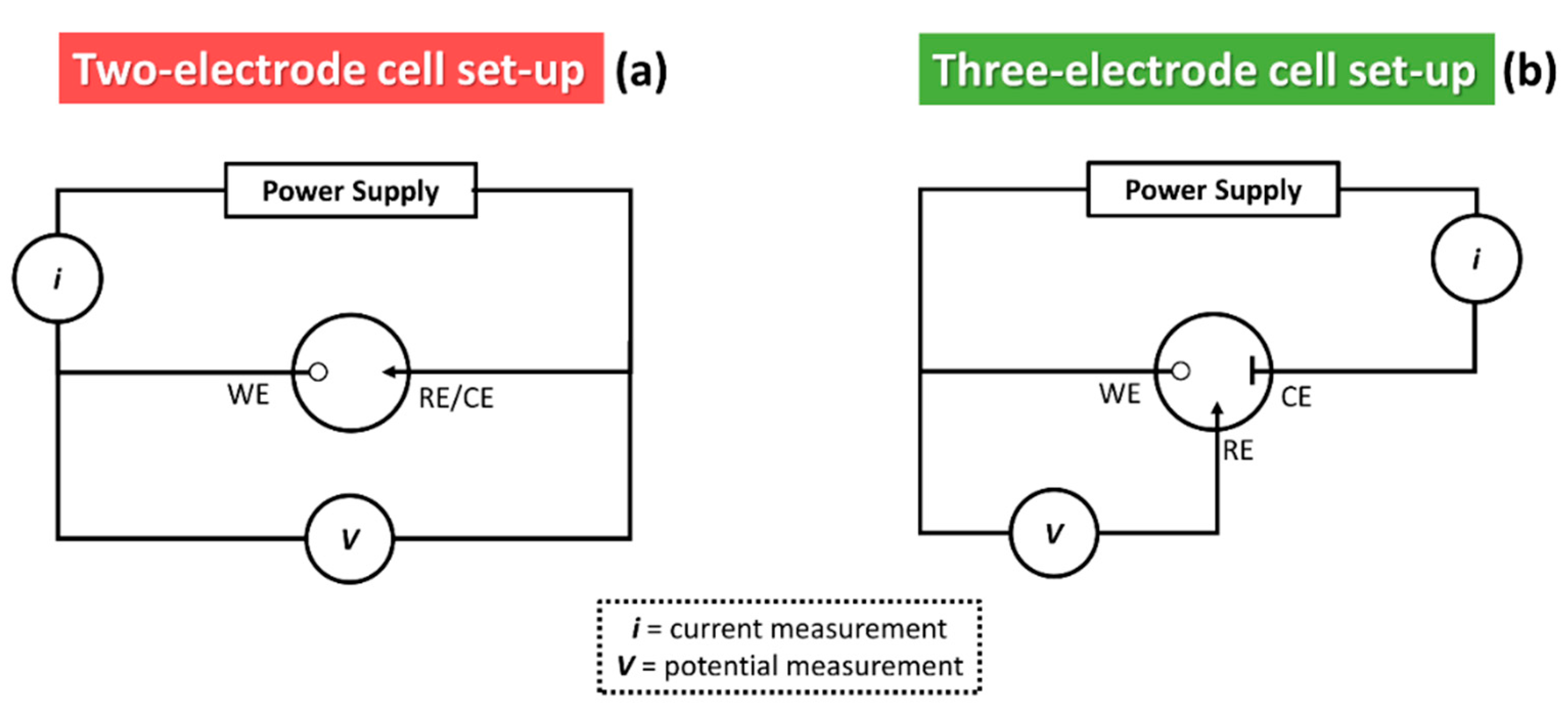
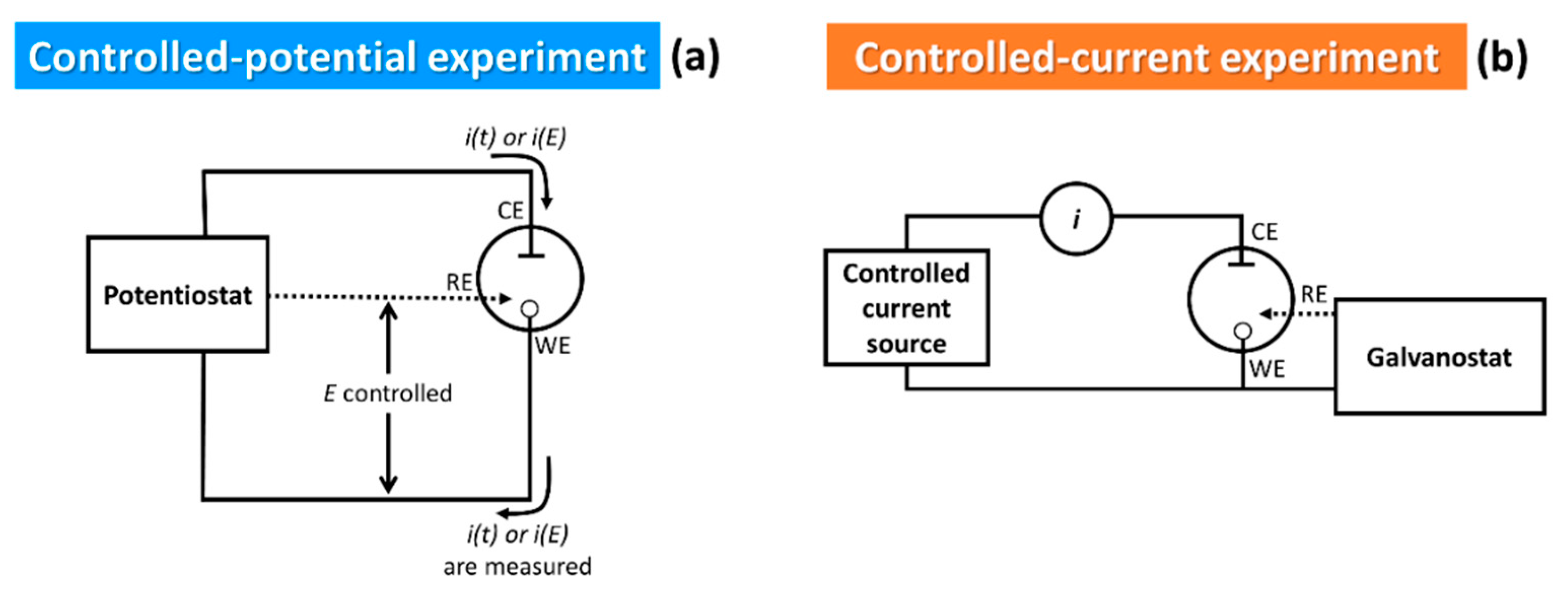
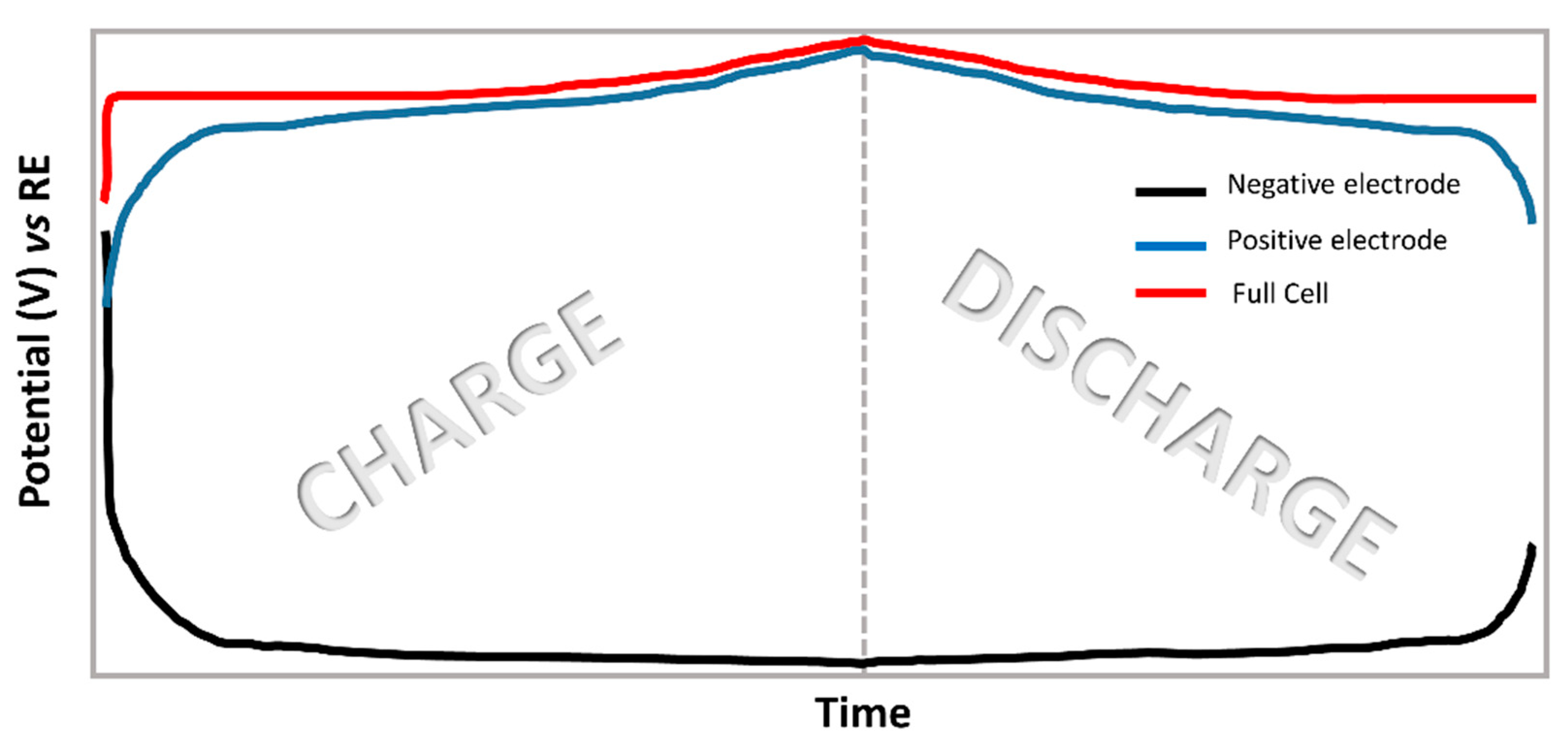
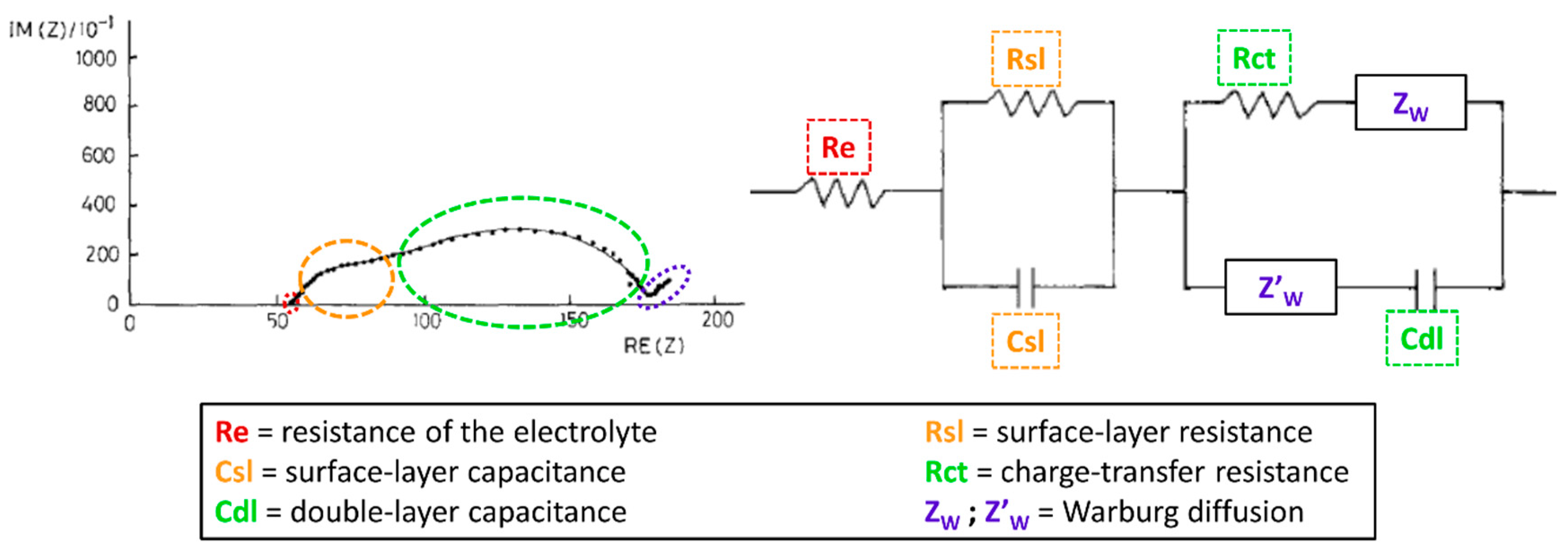
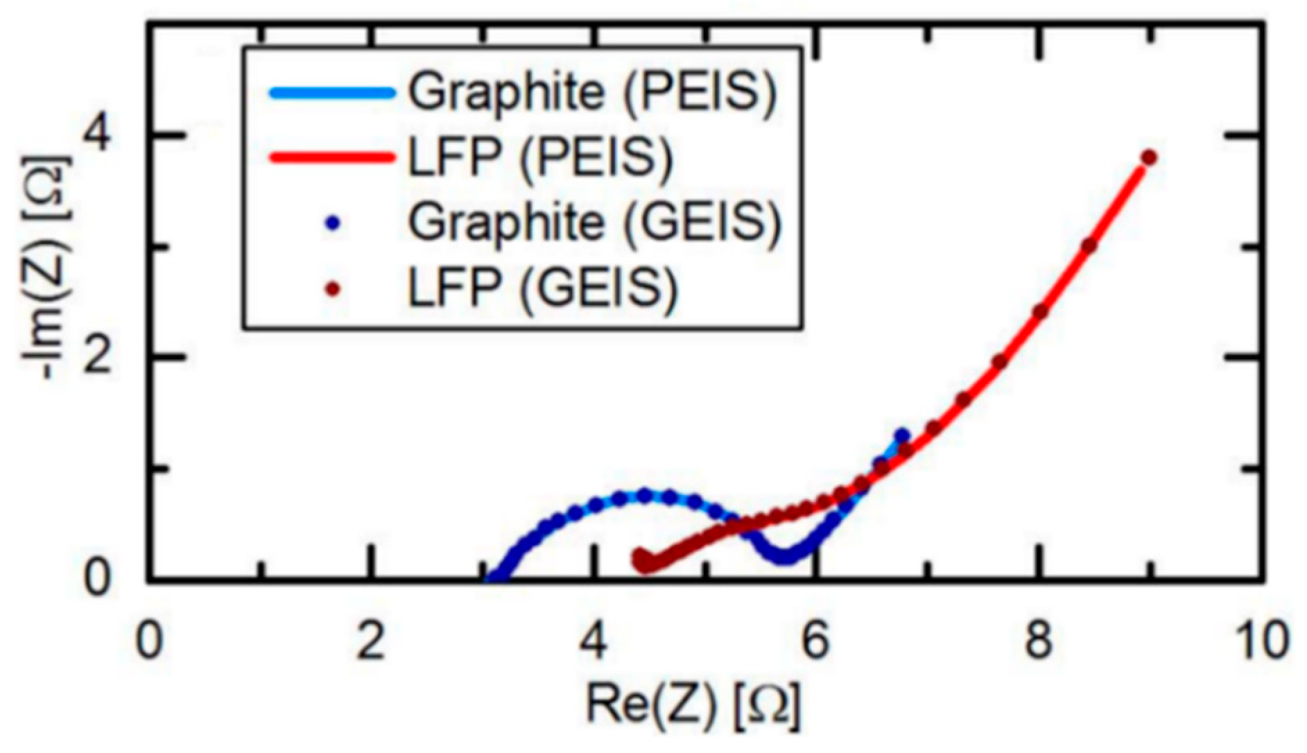
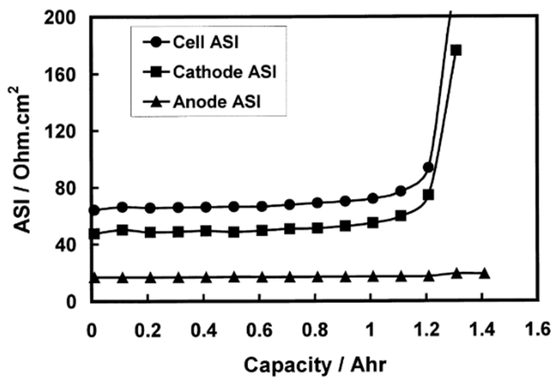
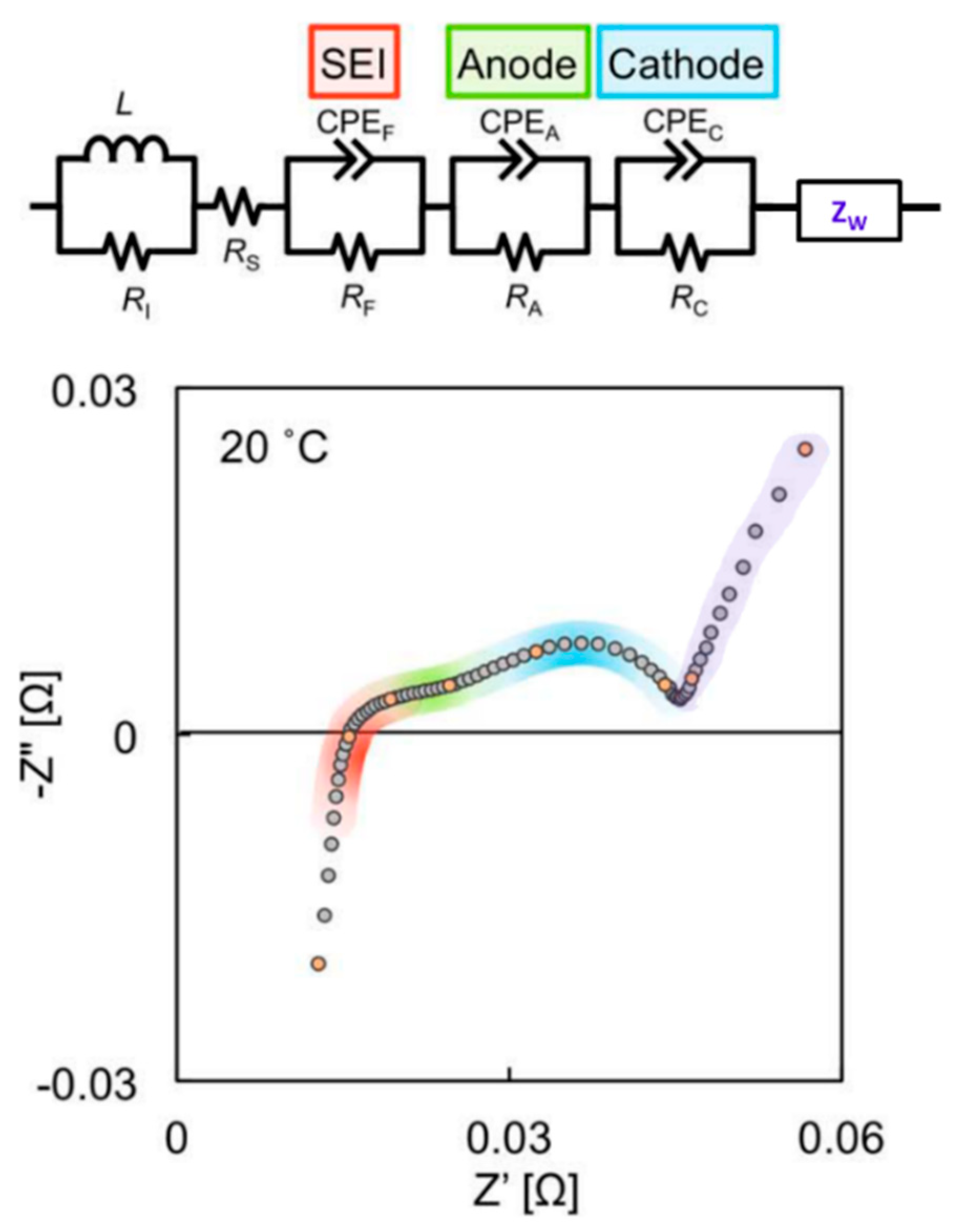
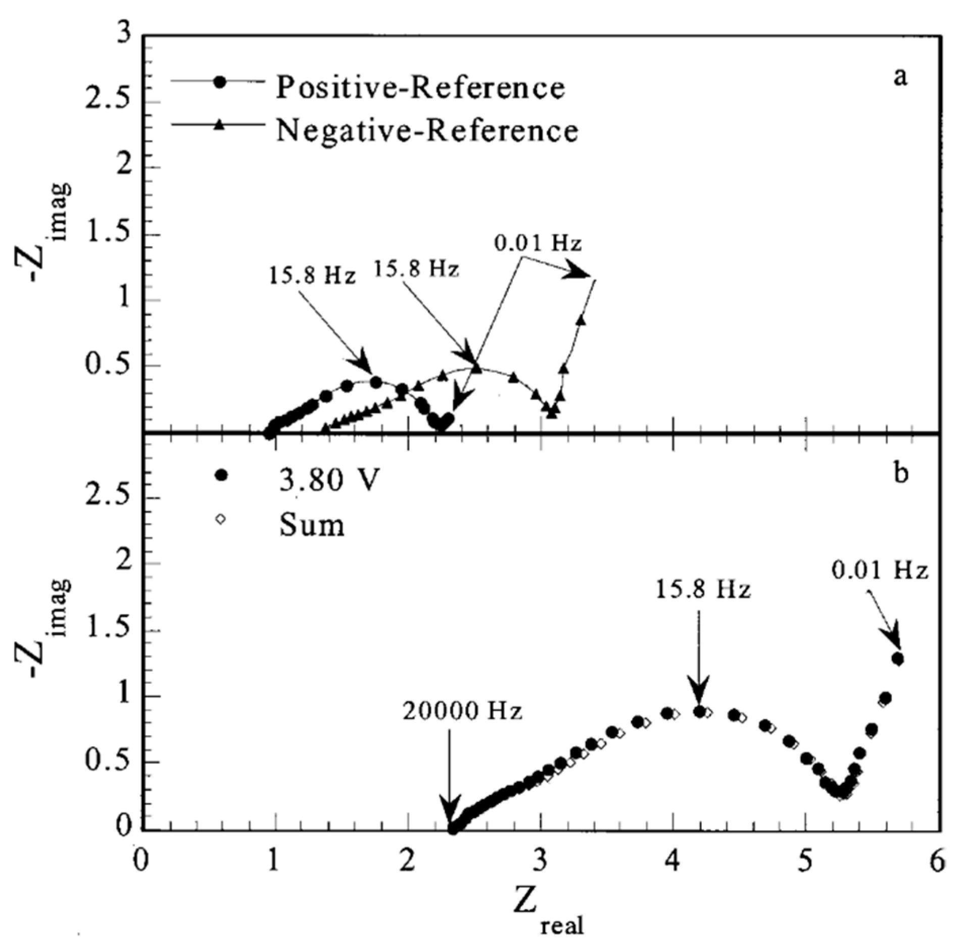
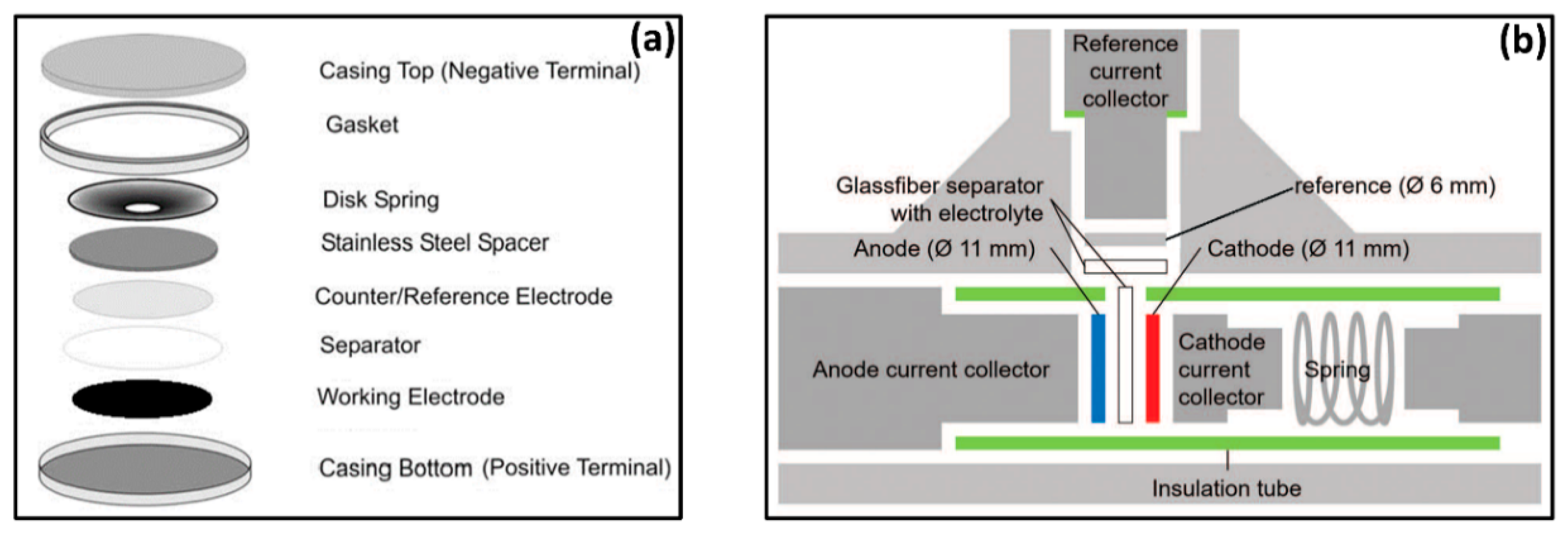
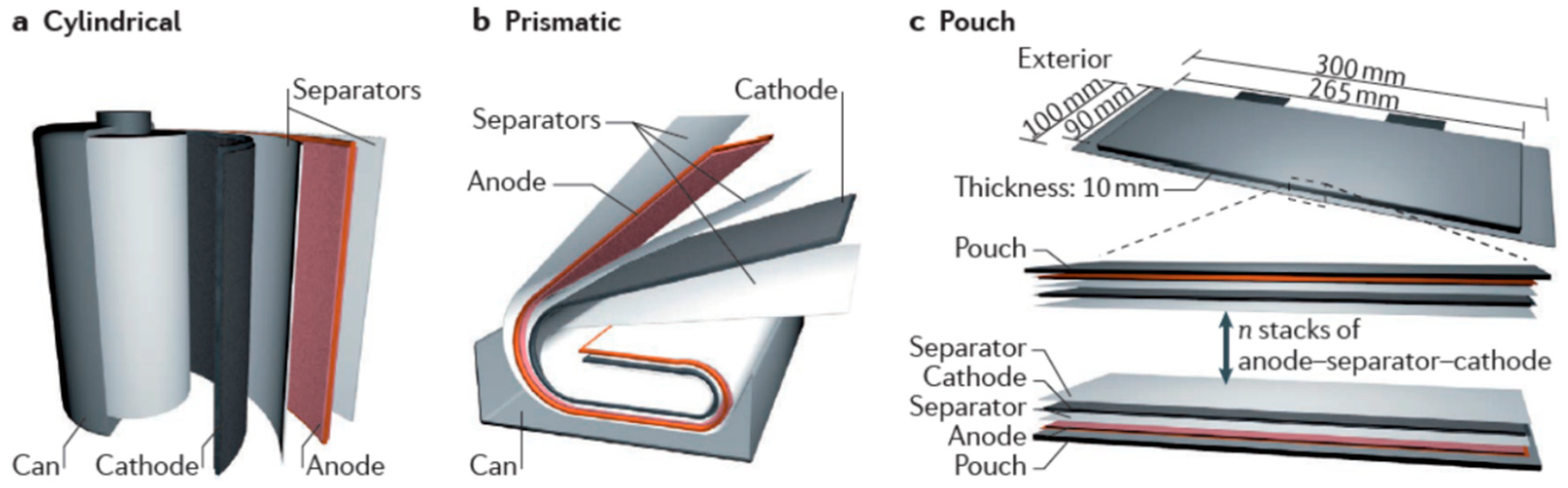
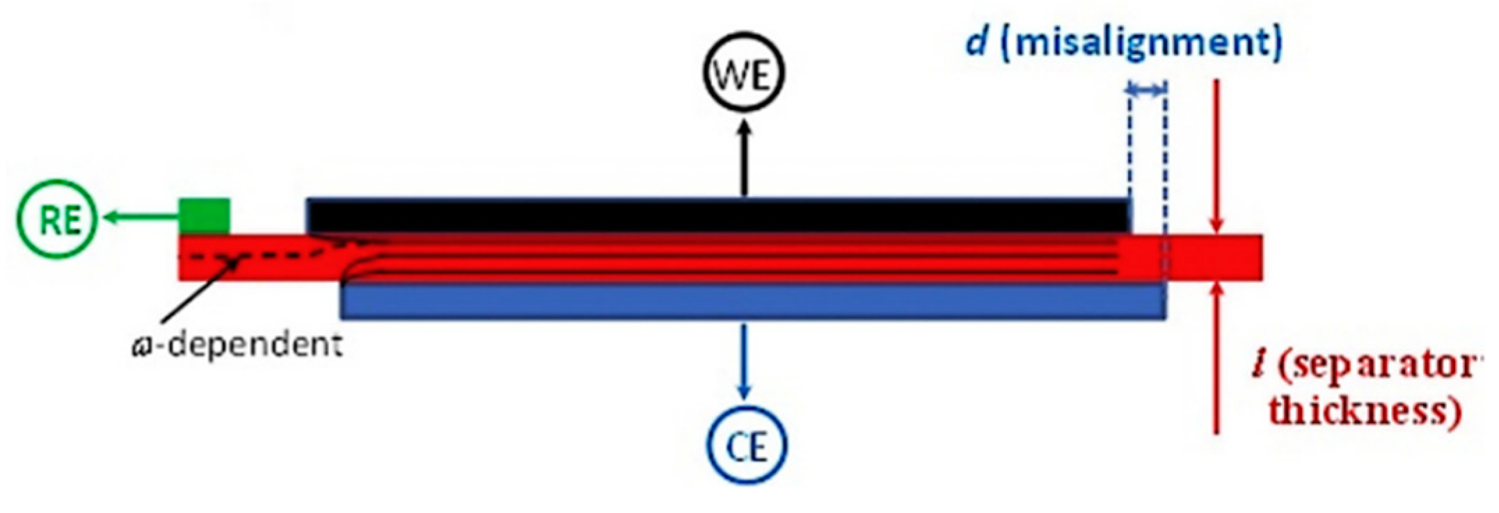
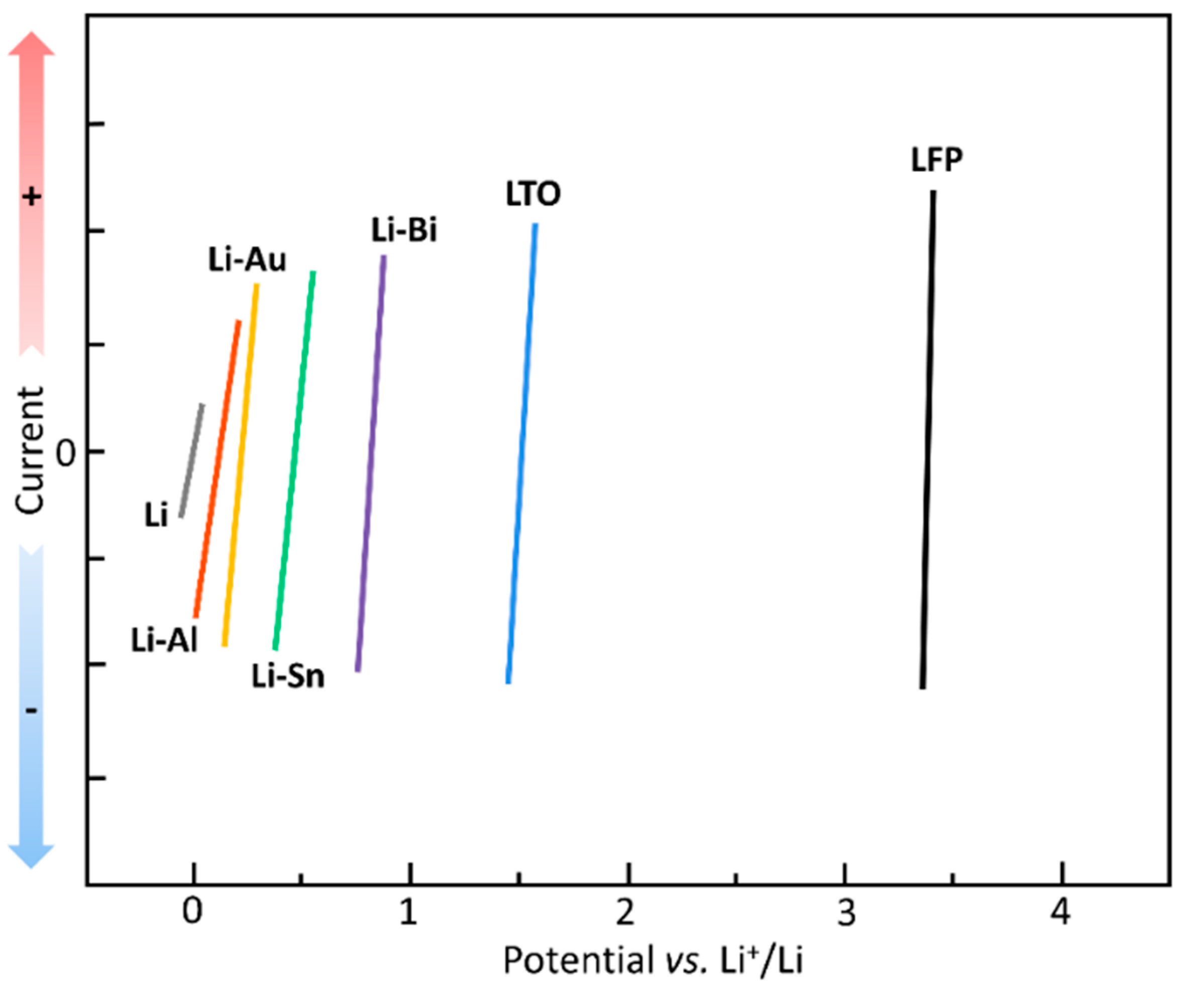
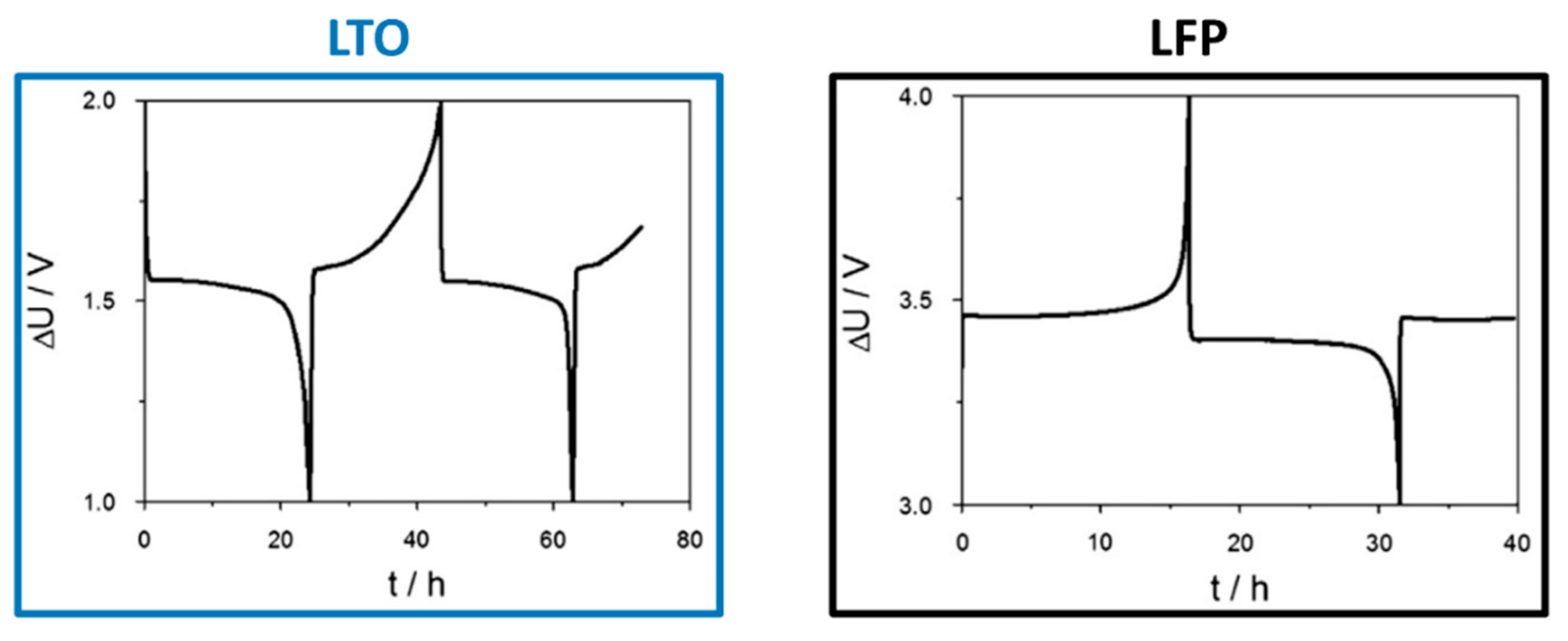
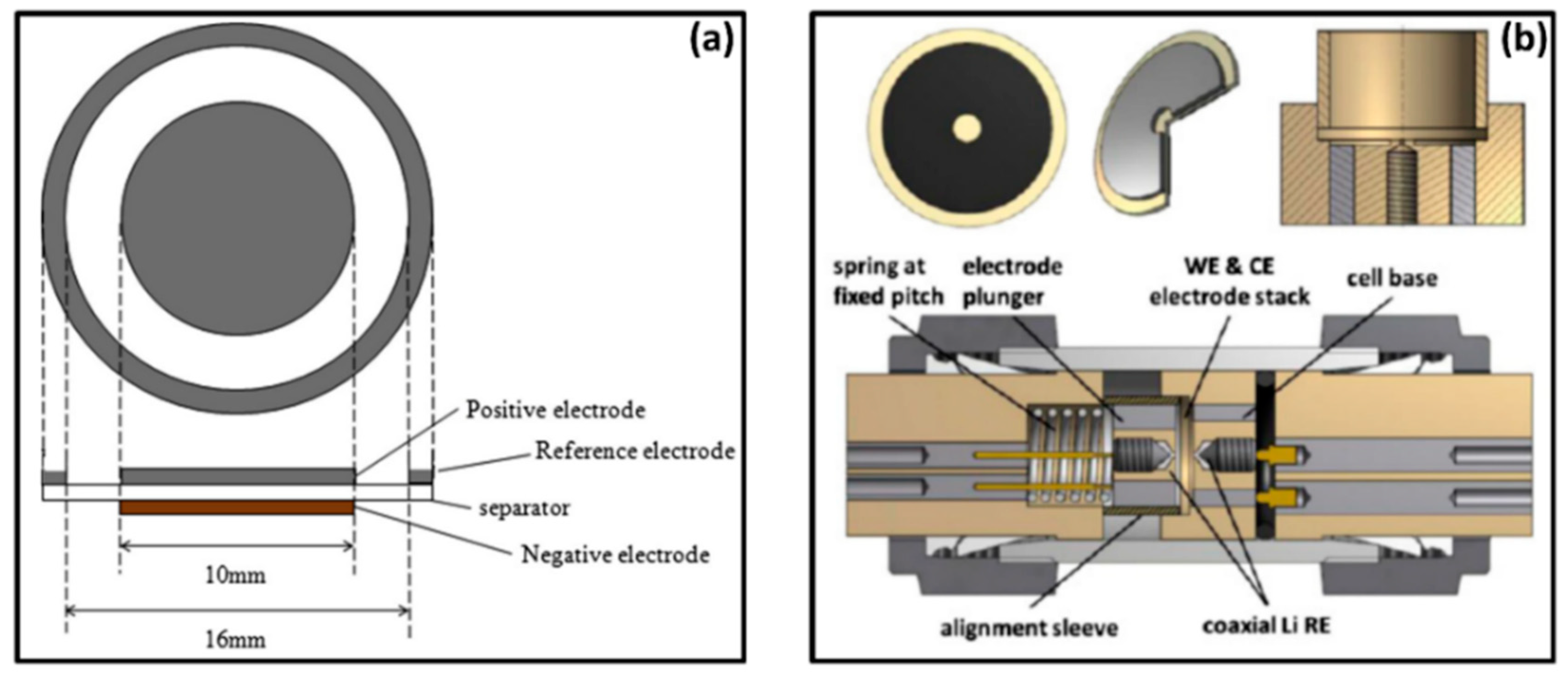
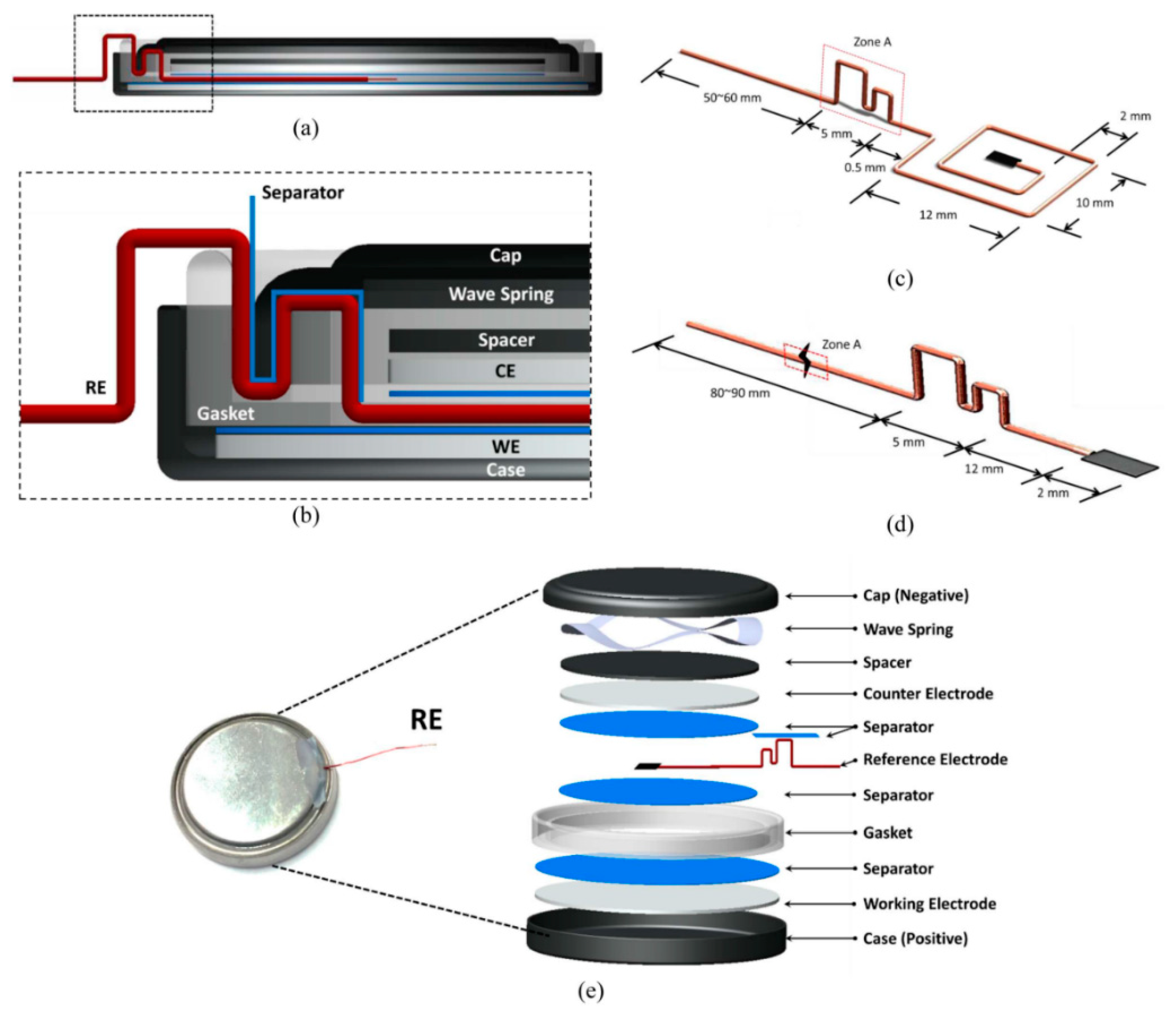
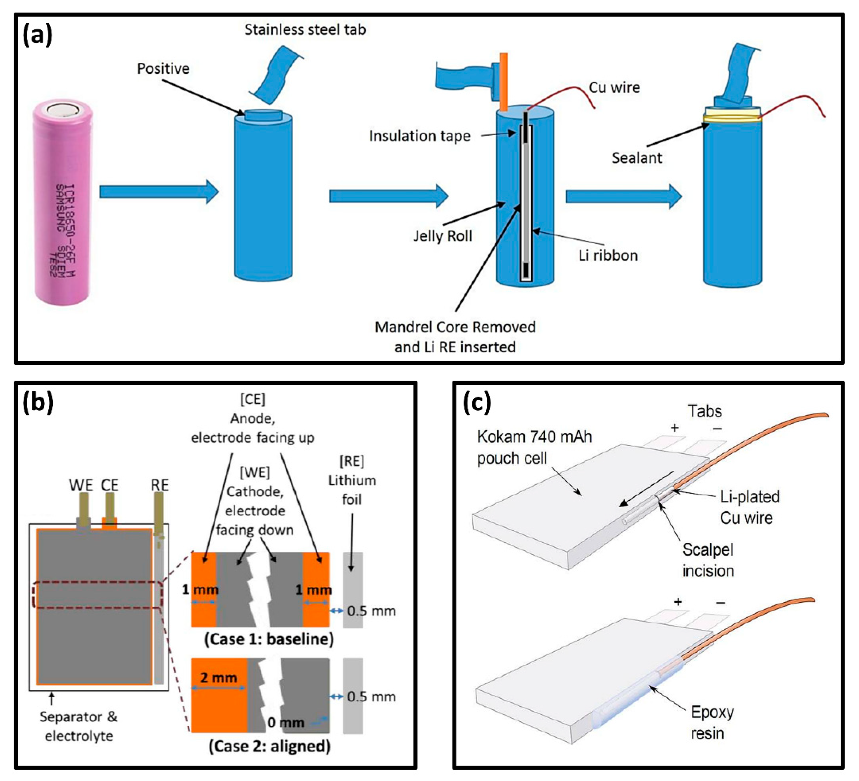
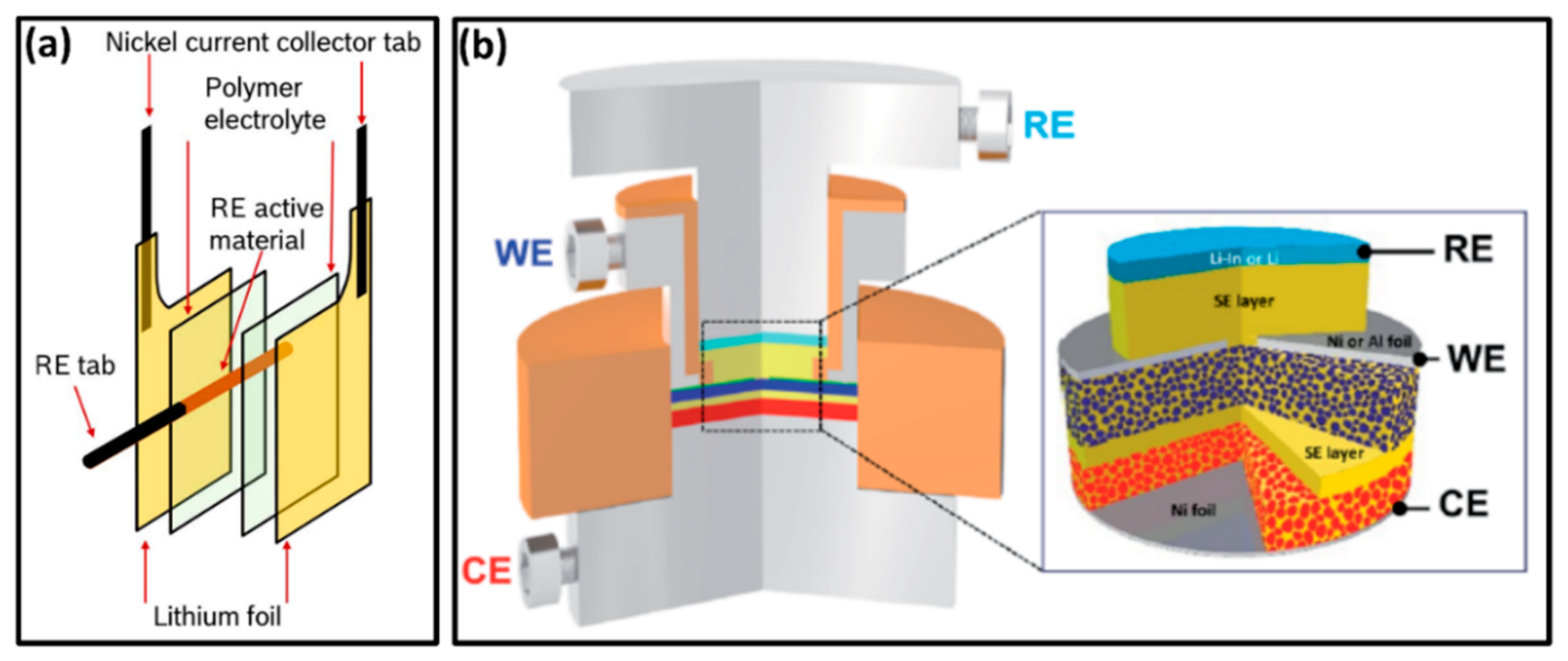
© 2019 by the authors. Licensee MDPI, Basel, Switzerland. This article is an open access article distributed under the terms and conditions of the Creative Commons Attribution (CC BY) license (http://creativecommons.org/licenses/by/4.0/).
Share and Cite
MDPI and ACS Style
Raccichini, R.; Amores, M.; Hinds, G. Critical Review of the Use of Reference Electrodes in Li-Ion Batteries: A Diagnostic Perspective. Batteries 2019, 5, 12. https://doi.org/10.3390/batteries5010012
AMA Style
Raccichini R, Amores M, Hinds G. Critical Review of the Use of Reference Electrodes in Li-Ion Batteries: A Diagnostic Perspective. Batteries. 2019; 5(1):12. https://doi.org/10.3390/batteries5010012
Chicago/Turabian StyleRaccichini, Rinaldo, Marco Amores, and Gareth Hinds. 2019. "Critical Review of the Use of Reference Electrodes in Li-Ion Batteries: A Diagnostic Perspective" Batteries 5, no. 1: 12. https://doi.org/10.3390/batteries5010012
Note that from the first issue of 2016, this journal uses article numbers instead of page numbers. See further details here.