Large-Scale Pumped Thermal Electricity Storages—Converting Energy Using Shallow Lined Rock Caverns, Carbon Dioxide and Underground Pumped-Hydro


1
Hydroclapeyron, Altair, 35800 Dinard, France
2
Laboratoire de Génie Civil et Génie Mécanique (LGCGM), University of Rennes, 35000 Rennes, France
*
Author to whom correspondence should be addressed.
Appl. Sci. 2019, 9(19), 4150; https://doi.org/10.3390/app9194150
Submission received: 15 July 2019
/
Revised: 17 September 2019
/
Accepted: 23 September 2019
/
Published: 3 October 2019
(This article belongs to the Special Issue Pumped-Storage Hydropower Plants)
Abstract
:Featured Application
This work relates to the design of long-duration electricity storages at low capital cost and at medium-high Round Trip Efficiency, using artificial underground caverns, carbon dioxide and underground pumped-hydro.
Abstract
A fast-paced energy transition needs a higher penetration of renewables, of heating and cooling in the worldwide energy mix. With three novelties 1-of using shallow high-pressure LRC (Lined Rock Cavern) excavated close to storage needs, 2-of using a slow-moving CO2 piston applying steady pressure on the hydro part of UPHES (Underground Pumped Hydro Energy Storage) and 3-of relying on inexpensive thermal stores for long-duration storage, CO2 UPHES coupled with PTES (Pumped Thermal Electricity Storage) could become, at expected Capex cost of only 20 USD/kWh electrical, a game-changer by allowing the complete integration of intermittent renewable sources. Moreover, even though this early conceptual work requires validation by simulation and experimentation, CO2 UPHES as well as UPHES-PTES hybrid storage could also allow a low-cost and low-emission integration of intermittent renewables with future district heating and cooling networks.
1. Introduction
Due to the need of reducing emissions of carbon dioxide (CO2), which is the major greenhouse gas quantitatively in the atmosphere, most countries have decided to increase the share of solar and wind energy in their energy mix. Unfortunately, those two renewable energies are dependent on meteorological conditions and their production are highly intermittent. Besides energy storage of short and medium durations fulfilling several major functions on national power grids, usually by the means of capacitors, flywheels and mainly batteries, long-duration storage (hereby defined as ensuring continuity of power in a range from 5 to 500 h) is expected to play an increasing role for allowing a higher penetration of intermittent renewables in the energy mix. In a 2018 report “Global Energy System based on 100% Renewable Energy-Energy Transition in Europe Across Power, Heat, Transport and Desalination Sectors,” for the Lappeenranta University of Technology in Finland, Ram et al. come to the conclusions that, if the whole energy supply shall depend on renewables by year 2050, the associated worldwide needs for storage shall be in the range of 64,000 GWh of electricity storage of all durations plus 40,000 GWh in the form of thermal storage for pure thermal needs [1]. Consequently, the availability of low-cost storage systems suitable for renewable energy should trigger the reduction of installed capacity of fossil fuel plants, not yet accomplished because of the discontinuous nature of the renewable energy resources. Regarding space cooling, a growing need where the novel storage has unique specific benefits, a 2018 study by the International Energy Agency projects a worrying increase of energy spent to produce cooling from 2000 TWh in year 2016 to 6250 TWh by year 2050 and a dramatic increase from 1.6 billion units of air-conditioners to 6.5 billion units during the same timeframe [2].
PHES (Pumped Hydro Energy Storage) is presently the main worldwide technology for the long-duration storage of intermittent energy such as solar and wind. Cavazzini extends the scope of PHES in the power grid beyond restoring the mere balance of supply and demand, to possibly provide much-needed frequency regulation services, requiring PHES to be operated over a wider range of power and with the shortest possible reaction time. The author concludes that an innovative design approach could overcome the remaining challenge where, under these operating conditions, reversible pump-turbine machines presently suffer from unstable behaviour [3]. Regarding long-duration as well as seasonal energy storage, Power to Hydrogen and Power to Methane are two field-proven technologies, however high Capex (Capital Expenditure) and low RTE (Round Trip Efficiency) of their present development stage presently preclude both of these technologies from being used for mainstream storage of electricity. An alternative technology, CAES (Compressed Air Energy Storage) is making progress by improving the value of its RTE through the development of AA-CAES (Advanced Adiabatic Compressed Air Energy Storage), however no grid-scale AA-CAES is yet available at this moment. A recent CAES concept for localized facilities such as hospitals, hotels, industrial centres, shopping malls and so forth, especially when coupled with production of intermittent renewable energy, is micro-CAES which has the capability to complement a relatively low RTE on pure electricity storage by the supply of cogenerated heat which can be needed for the heating and/or for the hot water consumption of those facilities, resulting in a higher hybrid efficiency for electricity plus heat. Tallini et al. provide an economic analysis of such a system in the framework of integration with photovoltaic energy [4].
Another technology for the long-duration storage of electricity, PTES (Pumped Thermal Electrical Storage), also called Power to Heat to Power, seems very promising due to the simplicity, the low Capex and the low embodied carbon of its energy storage within two liquid or solid thermal stores (such as water, vegetable oils, sand, boreholes in rock mass, etc.). Mercangoz et al. emphasize the benefits of using CO2 as the working fluid in a PTES, especially when water is the material for the thermal storages. Using detailed flow sheeting simulation, the authors achieves a RTE of 51% for a hypothetic pilot system of 1 MW using 4 machineries of efficiencies 80–86% and achieves a RTE of 65% for a hypothetic commercial system of 50 MW using 4 machineries of efficiencies 86%–91%, in both case for a CO2 based system operating between 122 °C and −3 °C [5]. Air or argon based power cycles operating over greater temperature ranges can obtain higher theoretical round-trip efficiencies (50%–85%), depending on the design parameters. McTigue et al. study in detail all sources of exegetic loss in an attempt to identify the maximum round-trip efficiency that can be achieved and conclude that with an ‘optimistic’ set of parameters that might be achievable with reciprocating devices, the thermodynamic round-trip efficiency could exceed 85% whilst the system simultaneously achieves an energy density almost an order of magnitude greater than for CAES [6]. Georgiou et al. perform interesting simulations on the compared performance of PTES versus another long-duration storage technology called LAES (Liquid Air Energy Storage) and state that round-trip efficiencies of PTES at the higher end of pressure ratios reach values of around 80%, adding that these predictions should be seen in light of component performance estimates that have not yet been proven, while for LAES, models show RTE of more than 55% with sufficient utilization of waste cold and heat, when a combination of these two factors is adapted [7].
Unfortunately, as far as pilot systems are concerned, the RTEs of present PTES currently hover around 25%–30% due to the limited efficiencies of two compressors and of two expanders working in gaseous or supercritical phase and due to other thermodynamic irreversibilities. For instance, Dietrich et al. realized in 2016 a model using butane as the working fluid and computed a maximum RTE of 27.3% [8]. While the Siemens Gamesa company expects a full-scale deployed system to reach in the future round-trip efficiencies of 50%, a RTE of only 25% has been so-far obtained in June 2019 in Hamburg, Germany after several years of development on a pilot plant of 130 MWh per week [9]. Although a dozens of concepts, experimental pilot beds and small-scale demonstration plants have recently entered in development, no grid-scale PTES has been proposed for construction so far. Considering the urgency of addressing climate change by scaling-up the percentage of solar and wind in the energy mix, it is a direction of this work to argue that exists a risk where large efficient gas compressors and gas turbines could not get developed fast enough and to offer the alternative route of a hybrid UPHES-PTES devoid of gas machineries.
Electrochemical storages such as batteries are increasingly used by grid-scale operators and in a growing variety of functions but will probably never be considered for long-duration storage because their shorter shelf-life and their heavy embodied-carbon consumed for the production of the battery and the mining of metals can only be compensated by a fast-cycling, meaning the operation of a high number of short storage cycles.
Due to the scarcity of suitable and readily approved new mountainous locations for PHES, several types of UPHES (Underground Pumped Hydro Energy Storage) have been considered for many years. For instance, Pujades et al. have studied UPHES in deep mines and open pit quarries and their influence on groundwater flow [10]. Gravity UPHES, operating as PHES with the difference that the lower reservoir is located underground, are relatively costly in investment because, to offer a sufficient density of energy storage, they require to use deep caverns or deep disaffected mines located at depth of 300–1200 m as lower reservoirs. Salt domes are geographically scarce, must be of sufficient depth and are not suitable to contain fresh water.
A few hydro-pneumatic UPHES were presented instead, using conventional hydroelectric pumps and turbines, where the difference of elevation is replaced by a piston of compressed air in the upper part of a cavern, each 0.1 MPa of pressure providing a 10-meter head. In 1986, SHELL Internationale Research Maatschappij B.V of the Netherlands filed a European Patent at EPO for such a UPHES [11]. Bi et al. studied in 2013 a model of compressed-air pumped-hydro in adiabatic as well as in isothermal processes with the prospect of burying pressurized reservoirs underground and of overcoming some efficiency limitations of CAES by the use of hydro pumps and turbine [12]. Unfortunately, air warms-up with compression during electricity charge and cools-down with decompression during electricity discharge. RTE is therefore significantly reduced due to these irreversibilities. However, as reported by Odukomaiya et al., it must be added that, at the Oak Ridge National Laboratory, a small-size aerial prototype of hydro-pneumatic energy storage was able to reach RTE ranging from 66% to 82% thanks to the innovative heating and cooling of the air with water spray and thanks to the utilization of waste heat [13]. In all cases, unlined natural caverns or unlined mines must also be located deeply underground to maintain the tightness of compressed air through a hydrostatic containment by ground water (i.e., a 1000 m depth to contain a pressure of 10 MPa). For both types of UPHES, gravity-type as well as hydro-pneumatic-type, the geographic availability of natural caverns or disaffected mines, close to actual locations of electricity production, electricity consumption or close to power transmission networks, is also overly limited.
Several improvements are therefore needed so that UPHES can bring significant value for the storage of solar and wind energy. Based on three directions of innovation, the purpose of this early conceptual publication is to address the relevance of a novel type of UPHES for the bulk storage of intermittent electricity by disclosing its leading principles. A hybrid solution of low Capex cost (20 USD per kWh referring to the sole electricity capacity), targeting a medium-high RTE (60%–70%) is proposed, making use of the reliability and efficiency of pumped-hydro equipment, of the emerging technology of shallow LRC (Lined Rock Cavern), of the slow displacement of a CO2-water interface and of the low Capex cost of large atmospheric thermal storages.
2. Methods
The genuine process to reach the concept of this novel energy storage was actually incremental and dense in back and forth evaluations of numerous alternative solutions.
The first direction of improvement is related to the underground pumped-hydro reservoir. Because natural caverns or abandoned mines are too scarce and too remote, because salt domes are not suitable for fresh water and because UPHESs of high depth are too costly to excavate and operate, the energy storage must be able to be easily excavated at shallow depth (50–200 m under surface). Because shallow UPHES cannot be of the gravity-type, the energy storage must make use of the hydro-pneumatic type. Because shallow hydro-pneumatic UPHES cannot contain elevated gas pressure through the usual hydrostatic pressure of ground water, tightness toward gas and hydro-water must be achieved with the help of a liner, as in shallow LRCs used for natural gas storage in Sweden [14] and later experimented for shallow CAES pilot programs in Japan [15] and in South Korea [16]. As water appears under three different functions in this work, as the liquid for hydroelectric energy, as the mean of thermal storage and as ground water possibly creating hydrostatic pressure, we opt to name “hydro-water,” the use of water as the liquid for hydroelectric energy.
Consequently, the novel underground PHES presented here uses artificial shallow LRC caverns for pressurized reservoirs. It is pointed-out that, at high operating pressures of 7–15 MPa, cylinder-shaped steel vessels in open-air locations not constrained by rock mass, cannot represent economical solutions for diameters larger than 5 m, since large aerial pressurized vessels benefit of no effect of scale in terms of mass of construction materials and since large thickness of metal are too costly to assemble related to the welding work and its certification. Carbon fibre vessels of a large volume also enjoy no effect of scale and remain uneconomical compared to pressurized caverns.
The second direction of improvement addresses the warming and cooling irreversibilities created by the compression and expansion of air as the hydro-pneumatic gas. To offer an acceptable RTE, the novel storage needs to replace air pushing on hydro-water by a fluid remaining at constant pressure despite the large variations of volume induced by inflows and outflows of hydro-water. Obviously, gas cannot achieve this constant pressure criterions, so the novel idea is to move hydro-pneumatic UPHES into the domain of liquid-vapour equilibrium (optionally supercritical). Consequently, due to the phase changes expansion and contraction of a fluid at constant pressure, during water inflows (electrical work supplied to the pump), as well as during water outflows (electrical work recovered by the turbine), most of the unwanted warming and of the unwanted cooling of the previous hydro-pneumatic gas solutions are eliminated.
Since the required volume of pressurized UPHES would grow too large and therefore too costly for long duration storage (5–500 h of operation at nominal power), the third direction of improvement is to realize that the storage of energy per-se must be diverted elsewhere for energy storage of long duration. We opt for large, low-cost, insulated, atmospheric, thermal pits. It will be explained below how a pumped-hydro LRC cavern, coupled with a proper fluid, can become an outstanding locus of conversion from electricity into heat transfer, as well as from heat transfer into electricity.
The following section reports on the data extracted from literature review. It defines the chosen options for the system and the associated economic evaluation by means of Capex (Capital expenditures) and RTE. Capex of storage is expressed in terms of USD/kW for the power of the conversion system and in USD/kWh for the available energy capacity. RTE is the expression of the ratio of recoverable electricity to the electricity consumed to fulfil storage and is expressed in percentage.
3. Results of Literature Review and Economic Assessment
3.1. Novel Use of Existing LRC Cavern for UPHES
3.1.1. History and Characteristics of LRC Caverns
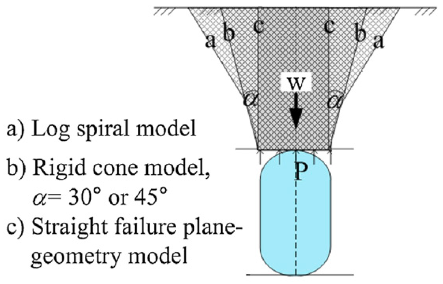
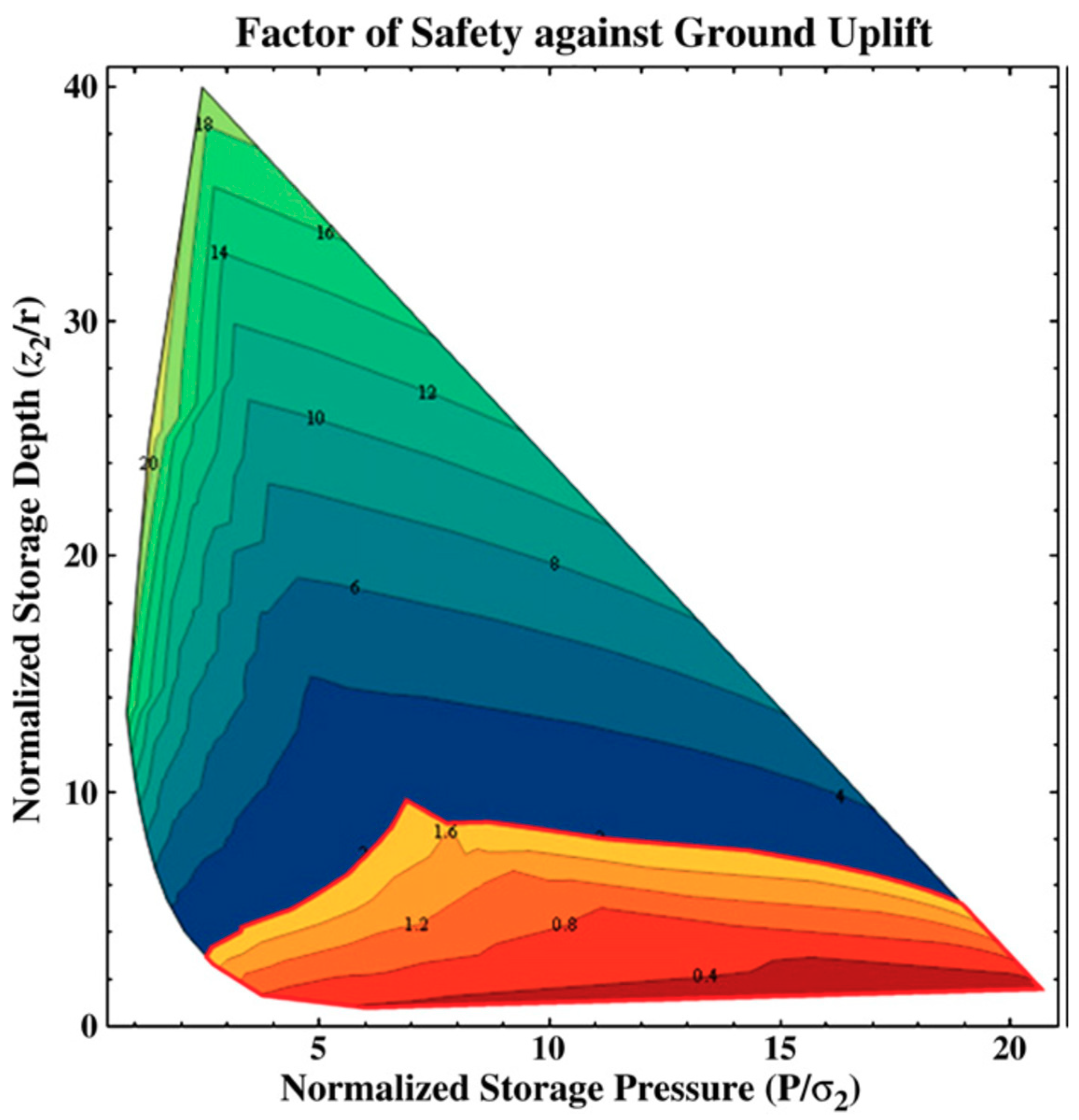
Research and development on LRC cavern started in Sweden in the 1990’s for the storage of natural gas under shallow depth and under high pressure till 28 MPa (including some tests at 52 MPa) [14]. The main distinctive features of LRC are the following: - the pressure of the gas is opposed by the surrounding rock mass, - a liner of steel or polymer is taking care of absolute tightness, – a low ratio of cavern diameter to the thickness of rock-cover protects the cavern against the risk of ground lift-up thanks to the built-up of a near-cone induced by the coefficient of friction of the rock material, as illustrated by two of the three models of Figure 1. Kim et al. have extensively simulated from Sweden trials the conditions of this lift-up and performed sensitivity analyses on 20 variable factors [17]. From their work, Figure 2 shows an assessment of the safety factor against lift-up depending on normalized storage pressure and on normalized storage depth. Perazzelli et al. studied several design issues of LRCs in 2015, for their possible application to CAES, including ground uplift, buckling of liner, cycling and fatigue and concrete plug [18]. To evaluate the integrity of cavern sides, in 2016, Tunsakul et al. performed a study of fracture patterns of rock mass around a pressurized storage cavern based on the element-free Galerkin (EFG) method with a cohesive crack model. Quite logically they mention that a value higher than 1.2 is preferred for the local stress coefficient K0, equal to the pressure horizontally borne by the rock mass divided by the vertical pressure induced by gravity [19]. Fortunately, for shallow grounds below 200 m depth, the condition of medium-high K0 (i.e., value of from 0.8–1.5) is met for a high share of rock masses on Earth.
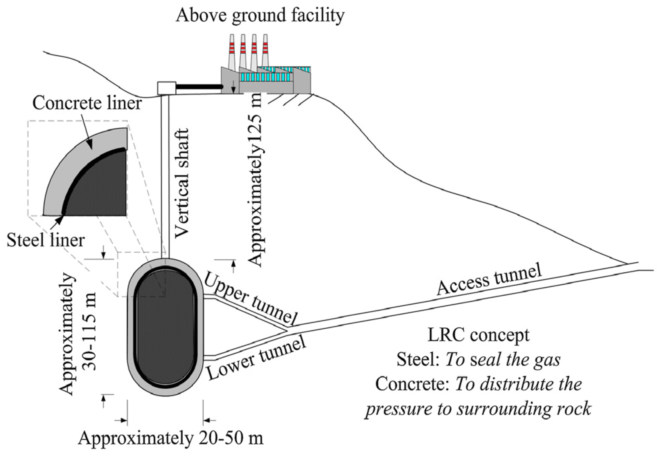
The Swedish program, accomplished with the partnership of the French company Gaz de France (nowadays named ENGIE) started in1988 by a pilot test of three shaft-shaped caverns of 4.4 m diameter and of 15 m height at a shallow depth of only 50 m in the Grangesberg granite mountain. Tested liners were steel, thinner stainless steel and polymer sheets. Later, a larger evaluation and commercial operation program was realized after 1999 at the Skallen mountain, using four large shaft-shaped caverns 36-meters in diameter, 50 m in height, 40,000 m3 volume, at a depth of 115 m, with a large cupola and a curved form bottom [14]. One illustration is shown on Figure 3. The host rock in the area is crystalline gneiss of good quality, intersected by amphibolite dikes of poor quality. After a test period of one and a half years, the facility has been in commercial operation as a part of the Swedish gas grid since early 2004 [20]. Despite tensile fracturing occurring in the unreinforced concrete layer placed between rock mass and liner, these caverns remain operational until this moment.
One LRC cavern was developed at Hokkaido (Japan) in 1990 using a decommissioned coalmine at a 450 m depth. Its function was the storage of compressed air for a pilot CAES at 8 MPa. This LRC takes the shape of a 57 m long tunnel, 6 m diameter. The liner is composed of butyl synthetic rubber inside a thin shell made of prefabricated concrete blocks, using more synthetic rubber at the liaison of blocks [15].
During 2010’s, a pilot LRC CAES has been built in South Korea, 100 m deep in a limestone ground. The pilot is composed of two tunnel-shaped LRC caverns of internal diameter 5 m. One cavern is using butyl sheets as liner, while the second cavern is using steel plates [16].
3.1.2. Use of LRC Cavern for Hydro-Pneumatic UPHES
LRC represent an attractive solution for hydro-pneumatic UPHES because they can be excavated in shallow grounds and close to area of electric production, of electric consumption or close to power transmission networks. Although there is not yet any LRC actually used for hydro-pneumatic UPHES, we do not anticipate particular constraints related to this specific usage. Although it exceeds the scope of this work, we also do not anticipate particular limitations in the further use of LRCs for most other pressurized storage utilizations such as CO2 sequestration and storage, hydrogen storage, methane storage and so forth.
In all cases, to limit rock failures to unavoidable low-amplitude tensile fracturing in the vicinity of cavern periphery and to avoid stepping into the domain of shear fracturing, it is recommended that the maximum pressure operated in the cavern does not exceed the uniaxial compression strength of the rock mass, which is usually higher than 15 MPa for most rock formation. In the case of soft rock mass, usually of low Young’s modulus (i.e., lower than 10 GPa), large radial displacements of rock walls must be avoided to hinder a heavy tensile fracturing of the thin concrete shell protecting the liner, as well as to hinder a later buckling of the liner itself at depressurization [18]. This can be accomplished by a high-pressure cement-grouting of the rock mass to a radial distance of at least one diameter, creating a somehow synthetic rock mass of higher uniaxial compression strength and of higher Young’s modulus.
Issues related to fatigue of the concrete shell and liner are of course linked with maximum and minimum pressures during operations, to the quantity of cycles along the cavern lifetime (40 years expected), to the quality of the rock mass and finally to the shell and liner themselves. Perazzelli et al. have conducted thorough simulations on this subject [18]. Another issue is the liner compatibility with fluids contained in the cavern. For instance, CO2 has a strong oxidizing effect on carbon-steel in presence of humidity. Moreover, CO2 shows a high permeability to elastomer membranes as well as to several other polymer materials.
Another consideration about LRC cavern, also not specific of use for hydro-pneumatic UPHES, is the high risk of damaging the liner by the hydrostatic pressure of ground water when the cavern gets depressurized for inspection or maintenance. For all caverns below ground water table, it is therefore compulsory to insert water drains between rock walls and the concrete shell. In that matter, taking benefits of available cliffs or hills, even of low-elevation, can be beneficial to excavate caverns above water tables.
In a different respect, although completely untested for UPHES as well as for other storage use, it shall be possible to take benefit of the mass of high-rise buildings (25–100 floors) to build a cluster of small-diameter shaft-shaped LRCs a few tens of meters under a thick concrete slab placed at the lowest level of underground parking lots. Subject to further geotechnical studies, this configuration of underground storage could become of interest whenever local or national administrations would enforce regulations for on-site Net Zero Emission requirements based on renewables + storage, in urban areas when land surface is highly constrained.
3.2. Replacing Air by CO2 at Liquid-Vapor Equilibrium in a Hydro-Pneumatic UPHES
3.2.1. Reaching Constant Pressure for a Hydro-Pneumatic UPHES
To avoid thermodynamic irreversibilities due to warming and cooling of air during compression and expansion, the novel storage offers to replace air pushing on hydro-water by a constant-pressure fluid at liquid-vapour equilibrium (optionally supercritical). Only one fluid, CO2, was found by this work to match the four criteria of being inexpensive, of having at ambient temperature a saturation vapour pressure compatible with the pressure range of the hydroelectricity industry (3–15 MPa), of being non-flammable and of being environmental-friendly in terms of depletion of the ozone layer. As this fluid happens to generate some greenhouse-effect in atmosphere, undertaking its sequestration underground is also considered beneficial. Although CO2 implies the complex use of an impermeable membrane to avoid losses due to its high solvability in water at high pressure, it allows to recharge and discharge electricity at constant pressure, roughly 5.7 MPa (570 m head) when ambient temperature is 20 °C (or roughly 420 m head in configurations where the receiving pound is located at ground surface 150 m above the cavern) or at much higher pressure when heated. Some semi-crystalline polymers such as PET (Polyethylene Terephthalate), Polyamide 11 (Rilsan), Nylon 6, Nylon 66 and metals such as aluminium foil are promising candidates for the assembling of an impermeable multiple-layer membrane, preferably quasi-adiabatic. The French national institute of research IFP Energies Nouvelles has extensive experience with permeation of CO2 and is interested to assist the definition, assembling and testing of a suitable membrane.
Although condensation and gasification of CO2 happens at nearly constant temperature and pressure in the UPHES LRC cavern or in a smaller dedicated LRC cavern located beside the main cavern, back and forth supply and removal of important amount of heat are compulsory to the phase changes of CO2. The system uses therefore a wide area of heat exchangers at the lower and upper parts of the smaller cavern. Spraying of droplets of CO2 pumped from the bottom of the cavern toward its cupola shall facilitate heat exchanges. Forced circulation of CO2 can assist to reduce temperature gradients and to enhance phase changes.
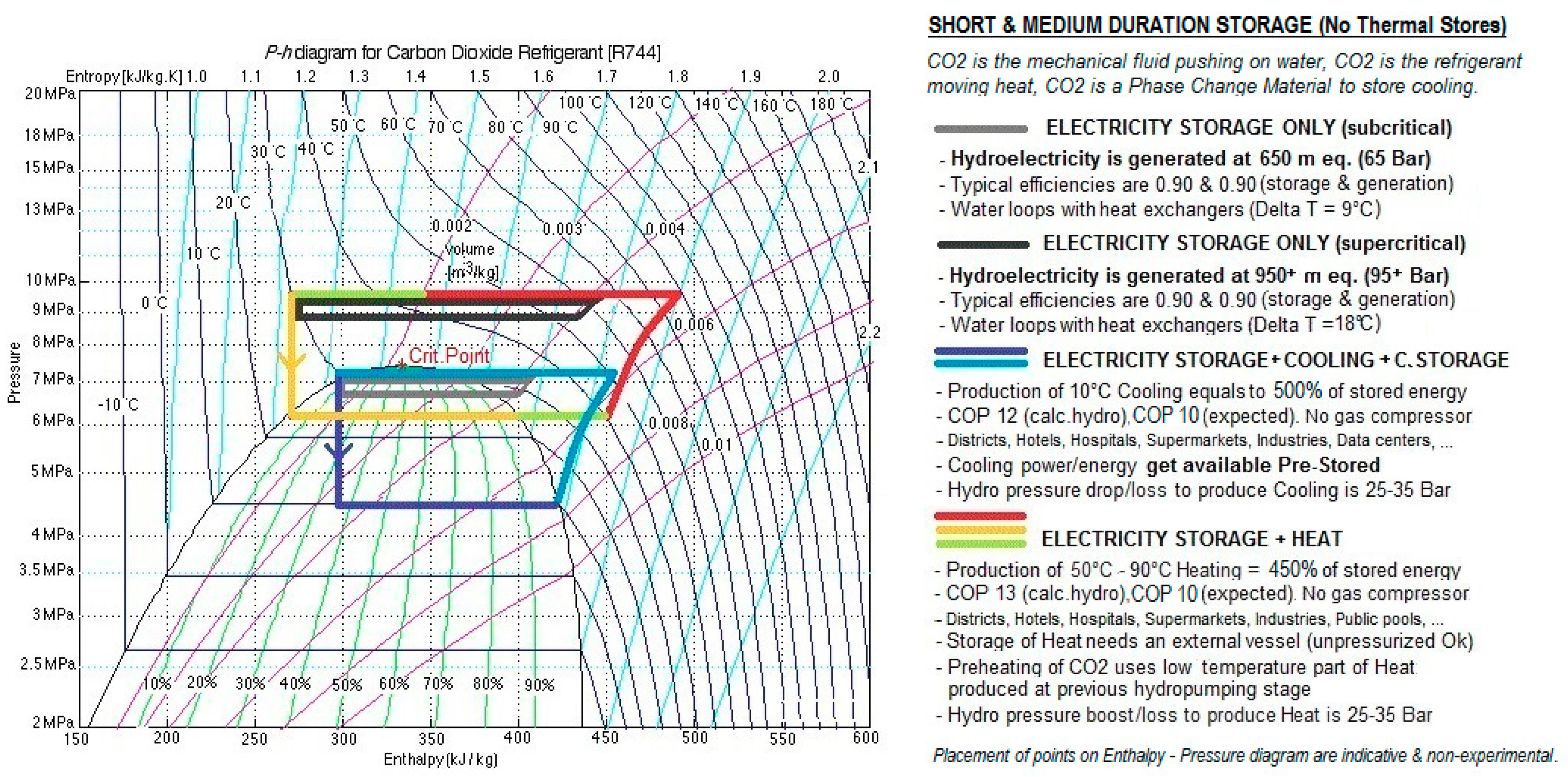
By performing simple calculations on enthalpy of CO2 latent heat, we can assess that the amount of heat displaced to perform a full change of phase of the CO2 mass at work (optimal CO2 mass to maximize the mechanical work by displacement of the maximum volume of water) is very significant and roughly equal to 500% of the hydroelectric energy charged in the cavern. The Pressure-Enthalpy diagram related to CO2 is appended in Figure 4. We intend to provide this figure just as an illustration of 4 different conceptual cycles, with no availability of actual data tables at this stage.
3.2.2. Operation as a Storage of Short or Medium Duration
Although, the highest benefits of the novel storage refer to long-duration storage, it can sometimes be used as a short-duration storage (less than 1 h of operation) or as medium duration storage (1–5 h of operation), particularly in off-grid area, where the novel UPHES can replace the ubiquitous use of diesel generators.
In such use, when heat or cooling is not needed by users, one single contraction of CO2 corresponds to one complete energy charge and one single expansion of CO2 corresponds to one complete energy discharge. Depending on ambient temperature at the location and on the location of the receiving pond, the pumped-hydro head goes to around 400–700 m. In such use, the large amount of hydro-water available internally gets used to buffer the large heat transfers, increasing and decreasing in temperature by around 10 K in each process.
3.2.3. Operation as Short-Duration or Medium-Duration Storage, plus as Heat-Pump
Quite often, heat or cooling is highly valuable, that is, for district heating and district cooling, supermarkets, hotels, hospitals, industries, call-centres and so forth and gets produced by the UPHES working in a slow and near-reversible way as heat-pump with an attractive COP (Coefficient Of Performance, equal to the ratio of useful thermal energy produced over electric energy consumed). We can read from Figure 4 that to export heating at temperature higher than ambient, we need to pump-in hydro-water at a pressure higher than 7 MPa. We can read as well that to export cooling at temperature lower than ambient, we need to let-out hydro-water at the turbine at pressure lower than 6 MPa. From simple computation of mechanical work, a COP of up to 10 can be expected, depending on required temperatures for heating or for cooling, related to the decrease of hydroelectric energy recovered.
For the particular case of cooling needs, it is important to stress-out that the cavern extracts heat at the same time it produces hydroelectricity at the turbine. Indeed, due to the CO2 mass acting as a PCM (Phase Change Material) in the quite uncommon pair liquid-gas for phase change, the cavern stores significant amount of cooling at the same time it stores electricity and additionally, does not need power to discharge such cooling. This unique feature could prove very useful for complementing intermittent renewable energies such as solar and wind to buildings having high cooling needs, such as most buildings in tropical areas, on-grid as well as off-grid. By enabling the continuous supply of hybrid energy (electricity + cooling), this feature could bring a radical solution to the worrying trend of fast-increasing energy spent worldwide for cooling, especially in China, USA, India and Indonesia [2,21].
The feature of CO2 acting as PCM for heating storage does not allow for the same benefit, since the production of heating only exists during charging of electricity and cannot happen without electricity supply. However, this issue can be fixed by the provision of an ancillary thermal storage (i.e., an insulated tank of hot water) allowing to fulfil heating needs around the clock, including outside of timeframes of electricity charging.
3.2.4. Economic Evaluation as a Storage of Short and Medium Duration, with or without the Heat-Pump Function. Comparison with Electrochemical Storage
Based on a system of power 100 MW and of energy capacity 400 MWh (4 h) and to calculations based on a compounded excavation cost of 300 USD/m3 for pressurized LRC (main cavern + smaller CO2-dedicated cavern), of a cost of 30 USD/m3 for the hydro-water reception pond, of a cost of 750 USD/kW for turbine + generator, of a cost of 350 USD/kW for pump + motor, a cost of 250 USD/kW for heat exchanger and of a cost of 150 USD/kW for building and ancillary equipment, the two features of using LRC cavern and of replacing air by CO2 bring the Capex of this short and medium duration storage of pure electricity to 1500 USD/kW Elec. + 200 USD/kWh Elec.
The unitary costs above come from estimations reached from discussions with professionals from underground civil works, from hydroelectricity and from chemical engineering.
The power component of Capex is simply the sum of the 4 items related to power (750 USD/kW +350 USD/kW + 250 USD/kW +150 USD/kW = 1500 USD/kW), while the energy component needs to be calculated in a table like Table 1 below. The limitation of this configuration appears immediately by realizing that stored energy is proportional to the high cost of excavation of cavern volume and that no significant effect of scale can be expected.
For value of energy density in this configuration, it is assumed that water takes 70% of the cavern volume and that recovered CO2 pressure gets limited to 90 bar, bringing a value of stored energy equal to 1.750 kWh per m3 (before loss at the hydro turbine).
Because of light thermal irreversibilities due to the temperature pinches at heat exchangers (i.e., 5 K or more at each side) occurring during the back and forth changes of phases of CO2, the RTE of this pressurized UPHES shall be slightly lower than the RTE of conventional gravity PHES or of gravity UPHES. In this respect, it is specified that although Figure 4 shows several thermodynamic cycles close to the critical point of CO2, it is likely that simulation and experimentation will encourage the authors to operate alternative cycles farther apart from this point, to ensure a better stability of the volumetric mass of the fluid as well as a better heat-exchange coefficient. RTE shall however be significantly higher than the RTE of hydro-pneumatic UPHES using air or any other gas in the sole gaseous phase. Our preliminary target for RTE in the simplest application for storage of short and medium duration, without the heat-pump function, is 73%, computed from typical efficiency of 90% each for the hydro pump set and the hydro turbine set and from 5% as an arbitrary valuation of the loss of work due to the temperature pinch at each of the two heat exchanges. When the system is requested to produce heating of mid-high temperature (50–80 °C) and/or cooling of mid-low temperature (5–15 °C), the absolute figure of recovered electricity in kWh needs to be lowered by a value approximately equal to 1/10th of the thermal energy exported or brought-in. Validation by simulation and experimentation are planned in a later stage and are absolutely needed to ascertain a more reliable value of RTE in each storage mode. A cooperation agreement has been signed with a French public research institute to assist in simulation of heat exchanges, in assessment of RTE and in the dimensioning of heat exchangers for a small-scale aerial prototype.
As a crude estimate of the pure Capex for the supply of heating and cooling, we can simply divide the Capex for electricity by 500%, which brings a Capex of heat and cooling to roughly equal 300 USD/kW Thermal + 40 USD/kWh Thermal.
Related to this use as storage of short and medium duration and compared to electrochemical storages such as batteries, whose Capex is expected to reach similar values of 200 USD/kWh by 2025–2030s, this novel UPHES offers the distinctive benefits of a longer lifetime (40 years expected), of not relying on foreign-sourced metals nor on high embodied-carbon metals, of not requiring challenging disposal nor recycling, plus of displacing a large amount of heating and cooling at each contraction or expansion of the CO2 mass.
3.3. A Novel Long-Duration Storage, Hybrid of Hydro-Pneumatic UPHES with PTES
3.3.1. Overall Considerations for Long Duration Storage
Long duration storage faces the tough challenge that it needs to require a very low Capex for energy capacity (i.e., below 50 USD/kWh) because in such storage, most of the available energy is left idle over long periods of time and delivers actual work only a couple of times per day, per week or even per month.
Another challenge specific of long-duration storage is to ensure a very low discharge rate (such as allowing energy losses of only 0.10%–0.25% per day).
Long duration storage shall also show a very low embodied-carbon. In such storage most of the energy capacity will be put at work only a limited number of times in the shelf-life of the storage, consequently any long-duration storage with embodied-carbon above a low threshold (in grams of embodied-carbon per kWh of energy capacity) would never be able to repay for its manufacturing footprint. This single issue, as much as Capex costs, is the main reason why most analysts conclude that electrochemical storages will remain restricted to the applications of short-duration (less than 1 h) and medium duration (1–5 h) timeframes. According from a year 2013 report from Stanford University, the Energy Intensity of batteries over their lifetime is only 2 to 10 despite the assumption of fast-cycling, while the Energy Intensity of pumped-hydro is around 210 [22].
In addition to the three constraints above, long-duration storages must show a reasonably high RTE like every other storage (i.e., higher than 60%), failing which the operational cost of stored energy would be heavily penalized by the cost of having consumed an amount of energy significantly higher than the amount of delivered energy. A high RTE is a major factor to charge a low LCOS (Levelized Cost Of Storage) to power users.
To this date, only conventional PHES fulfils this set of constraints, albeit with strong geographical limitations for additional projects, regarding new suitable locations as well as reasonably fast approval process.
3.3.2. Moving the Storage Capacity outside of UPHES, toward Thermal Stores
In response to the medium-high Capex for pure UPHES, a further innovative leap in technology and cost structure is needed as the third improvement of UPHES to achieve a Capex compatible with long-duration storage (5–500 h), one order of magnitude lower than the previously computed value of 200 USD/kWh for storages of short and medium duration.
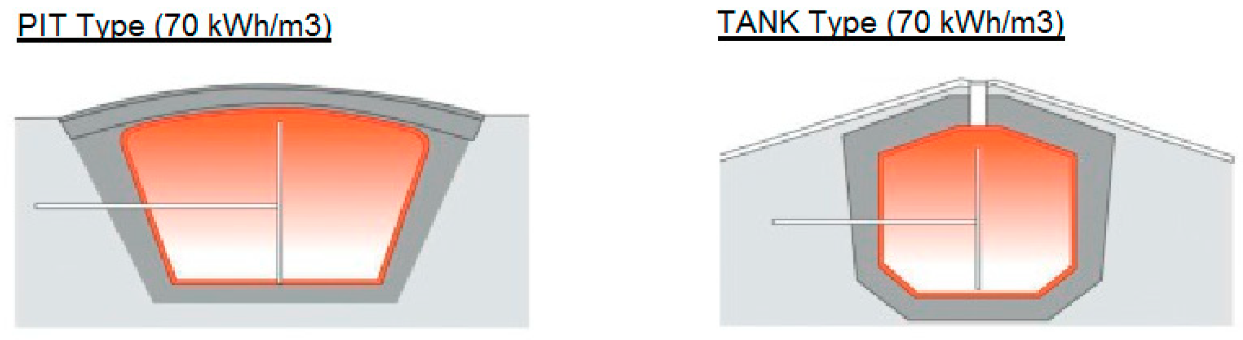
Since the required volume of such pressurized UPHES would prove too large and therefore too costly for long duration storage, the storage of energy must be diverted elsewhere. We opt for large, low-cost, insulated, atmospheric, thermal pits or thermal tanks as described in Figure 5. One pit, called Hot Store contains hot water at 95 °C, similar to the 40,000–200,000 m3 pits used in Denmark for seasonal thermal storage, losing only 0.1 K per day [23]. A second pit, called Cold Store contains a salted ice slurry at −20 °C.
The exergy from a thermal energy source is defined by the amount of mechanical work recoverable by a Carnot machine. Very interestingly, one shall realize that exergy of hot water is very high, much higher than energy of water subject to the sole earth gravity. For instance, exergy of water at 100 °C related to ambient temperature is equal to 12 kWh/m3. This is one order of magnitude higher than the mechanical energy of the same water in pumped-hydro, equal to 1.2 kWh/ m3 for a hydro plant of 360 m head.
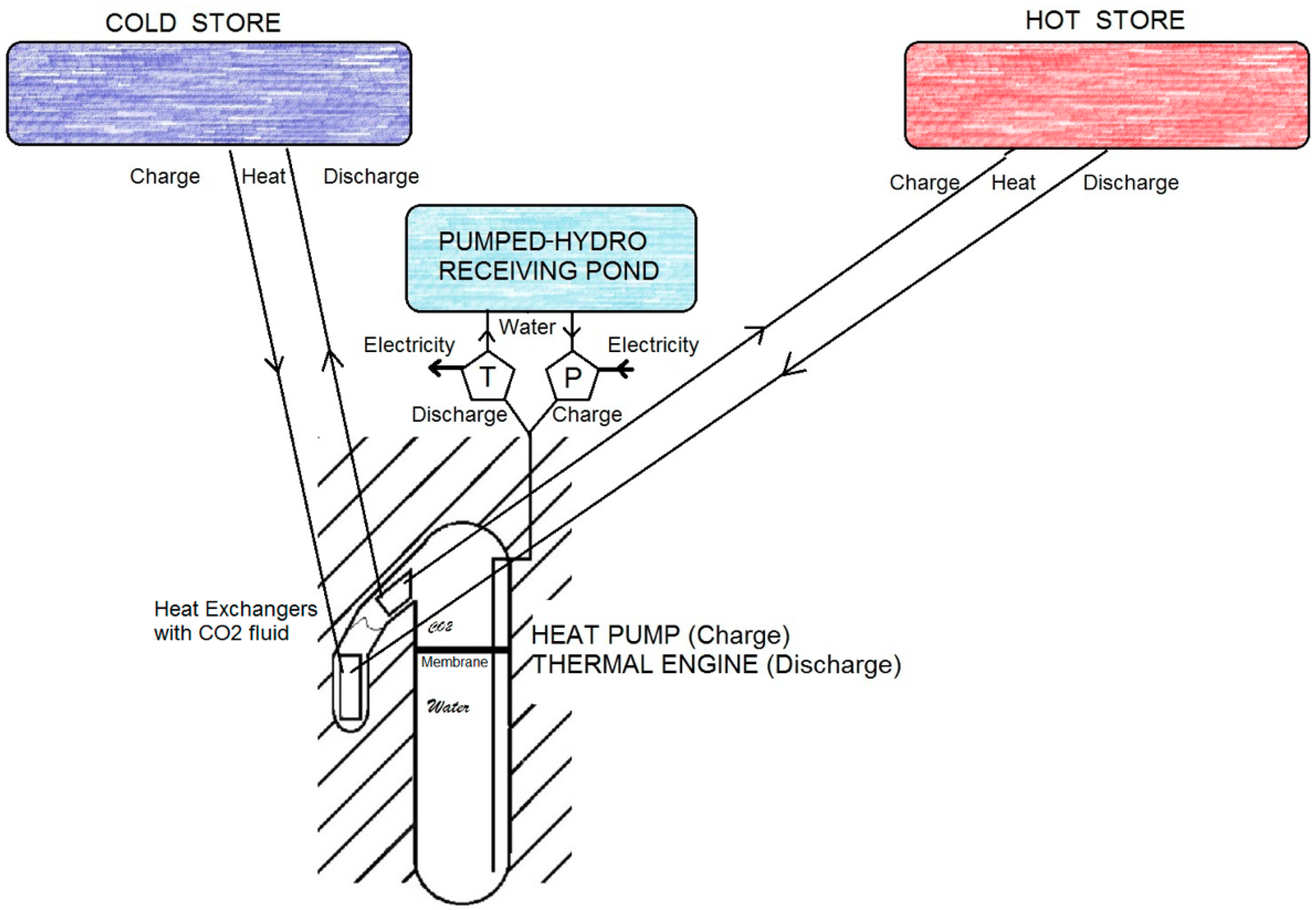
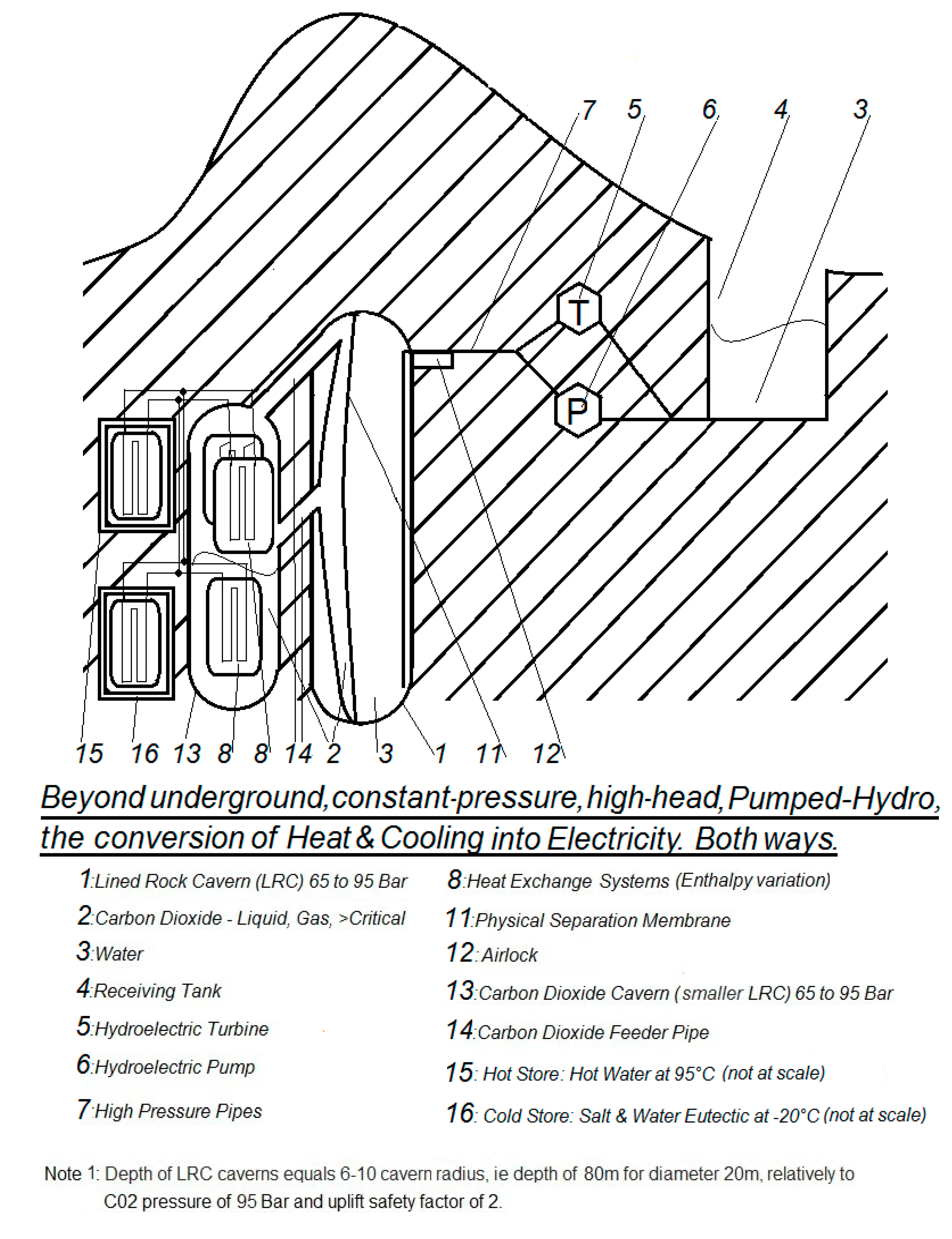
Figure 6 illustrates the principles of energy storage for a PTES using a UPHES for electricity conversion, while Figure 7 describes its main components. The radical innovation is that those two stores are thermally charged and recharged by the heat supplied and extracted during the time hydroelectricity is charging the UPHES, the slow moving CO2-water interface acting as a novel type of heat-pump.
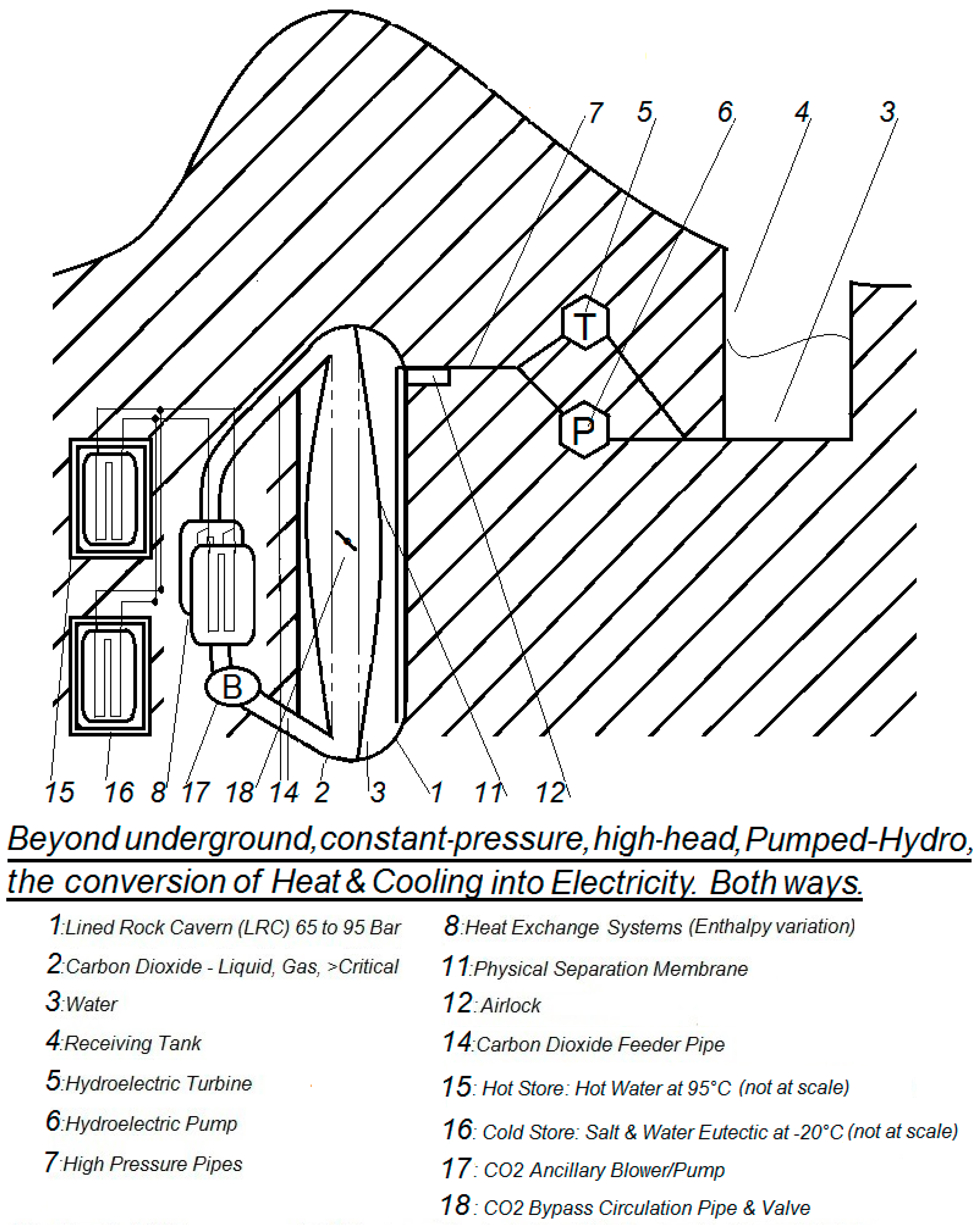
An alternative configuration is shown in Figure 8 below, devoid of the CO2 smaller pressurized cavern and where the necessary heat exchanges for CO2 happen instead by using an ancillary multiphasic CO2 blower/pump and external CO2 tubing leading to external heat exchanger(s). A bypass circulation pipe, fitted with a valve, is allowing the CO2 heat exchanges during ied times when the flexible membrane gets fully collapsed.
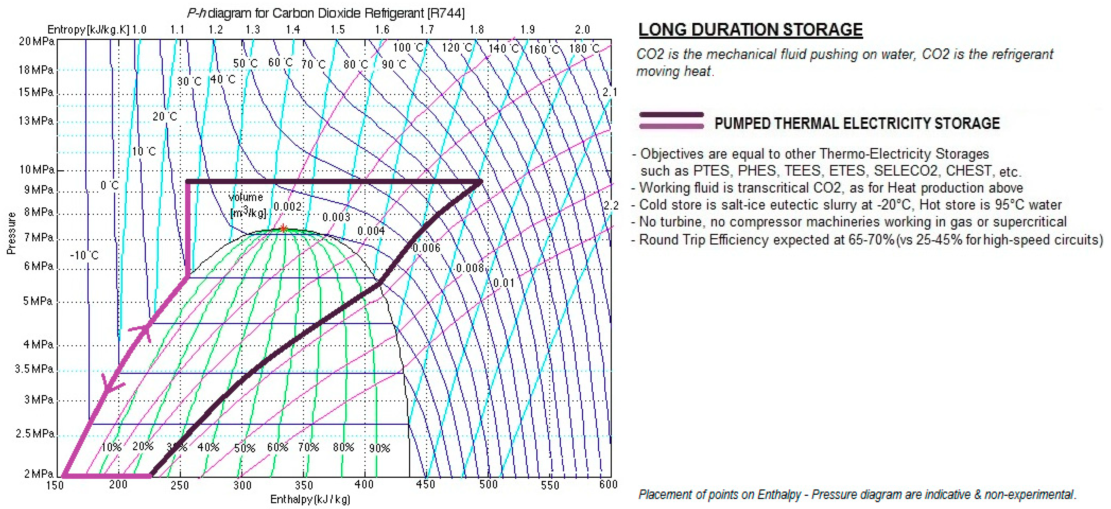
Figure 9 describes the system operation on the Pressure-Enthalpy diagram related to CO2. It is specified that placements of cycles vary with the level of completion/depletion of thermal stores, in particular with temperatures available from the Hot Store, and that optimal cycles for campaign of energy charge can be significantly different from optimal cycles for campaign of energy discharge.
For the Hot Store to work in the domain of 95 °C temperature, it is pointed-out that the pressure and temperature of pure CO2 in the cavern needs to exceed pressure and temperature of CO2 at the critical point (7.39 MPa, 31.1 °C). Such charging and discharging operations in trans-critical phases do not create specific irreversibilities of their own, except for the added complexity that overall heat exchanges for the expansion and contraction of supercritical CO2 at the upper constant-pressure ceiling needs to be performed by a glide of several heat exchanges at increasing and decreasing temperatures. It is specified than despite incursions of the working fluid in supercritical phase, the hydro-pump and the hydro-turbine remain the only two machineries needed by the novel storage.
A few companies are presently assisting to determine whether it could be valuable, instead of using pure CO2 at every occasion, to consider using binary/ternary mixtures of CO2 with selected molecules in low molar fraction, in order to displace the critical point of the CO2 mixture. If results of simulations and experiments were to prove positive, the novel storage could benefit of several types of CO2 mixtures, stored in several smaller dedicated caverns, to fulfil different situations (production of hydro mechanical energy only, co-generation of cooling, co-generation of heating, operation as hybrid UPHES-PTES).
It is pointed out as well that, compared to most other PTES, thermal stores temperatures selected by this novel storage are classified as low. Several other PTES are using temperatures of 500–750 °C for the Hot Store in pursuit of a higher storage density, at the cost of higher Capex of energy and of sophisticated operating procedures. Other PTES using CO2 as working fluid for energy conversion, albeit in continuous high-speed circuits of vapour compression differing greatly from the discontinuous expansion/contraction of CO2 in closed caverns, use temperatures of 120–140 °C for the Hot Store in order to gain in energy density [24]. Our analysis is that the challenge of lowering CO2 emission worldwide can only be achieved with the simultaneous higher penetration of low-cost and low-emission district heating and district cooling to residential buildings, office buildings and to some industrial developments, such as pulp and paper, pharmaceuticals, agro-food industry, textile and so forth. In particular, our vision objects to the growing installation of stand-alone electric heaters and stand-alone air-conditioners because in most countries those low-efficiency devices will remain powered by electricity of high carbon intensity, often from coal power plants, for many decades to come. Therefore, we foresee that the low temperatures selected for our thermal stores shall allow utility operators to readily integrate those stores, as well as the UPHES conversion caverns, for the production of low-cost and low-emission district heating and district cooling.
From a single transcritical cycle as drawn in Figure 9, one can also exploit the alternative of operating two adjacent cycles by drawing a third horizontal segment placed between the low-pressure and the high-pressure horizontal line, in such way that this segment is positioned at the outright saturation vapour pressure of the CO2 fluid for the ambient temperature (i.e., an horizontal segment, from 100% liquid phase till 100% gas phase, at a pressure of 58 bar when ambient temperature is 20 °C). By doing so, the storage operator gets, in discharge mode, the flexibility of prioritizing the thermal energy of the Hot Store towards heating networks or of prioritizing the thermal energy of the Cold Store towards cooling networks, while still being able to generate electricity from one of the two adjacent cycles, by using the environment to replace the missing store. Similarly, in charge mode, the operator enjoys the flexibility of using the environment to restore whatever imbalance by storing electrical energy in one of the thermal store whenever the second thermal store gets close to maximal capacity. This split in two adjacent cycles with the use of the environment could also prove being handy to initialize the storage system by charging independently the Cold Store and the Hot Store for a first time with the highest flexibility.
An additional benefit for this UPHES-PTES hybrid storage to work in the “low temperatures” domain is that this feature provides to the system a larger occurrence to increase its RTE, when very-low-grade geothermal energy or very-low-grade industrial heat gets available from the nearby environment (very-low-grade being hereby defined from being in the 50–65 °C temperature range). Because very-low-grade heat is considered “end-energy,” it comes “for free” and goes unaccounted-for in the definition of system efficiency. Consequently, RTE of the novel storage could exceed 100% in conditions where very-low-grade heat is available at sufficient power and temperature.
When an external source of low-grade energy is freely available (low-grade being hereby defined from being in the 65–95 °C temperature range), the same “low temperatures” feature of the working fluid shall allow the UPHES to work as an autonomous thermal engine, producing net-work without depending on thermal stores nor on external electricity source. Examples of such net production of electricity are the availability of low-grade geothermal energy or low-grade industrial heat. When the low-grade source of energy is of suitable temperature however of low power (i.e., of weak flow), the procedure is to include this inexpensive energy in the heating process of the CO2 mass or to store it in water tanks to operate only a few hours per day in net-work mode. Operational modes taking benefit of very-low-grade or low-grade energy usually require the use of the ambient environment as a secondary thermal source.
With or without the availability of external thermal sources supplementing the two thermal stores, in discharge mode the effect of applying a hot source and subsequently a cold source, to a stand-alone UPHES cavern creates a near-reversible thermal engine, slowly expanding/contracting CO2, pushing-out hydro-water to the hydroelectric turbine and subsequently sucking-in hydro-water back. The favourite configuration to maintain steady power is to rig two caverns A and B asynchronously in parallel to a single turbine set and to use two receiving ponds or one larger receiving pond, located at the ground surface. While cavern A pushes-out hydro-water at high pressure (9.5–15 MPa) thanks to the expansion of CO2 heated by 95 °C water at its evaporator heat exchanger, cavern B gets its condenser heat exchanger connected to a −20 °C coolant, reducing gradually its inner pressure down to 2 MPa and allowing hydro-water to be sucked-in from the surface with close to no pumping work. Before cavern A gets entirely emptied, cold CO2 of cavern B had been pre-heated or had been swapped with an external mass of pre-heated CO2 and get ready to take-over the pushing-out of hydro-water to the same turbine set thanks to the expansion of CO2 heated by 95 °C water, while cavern A gets prepared to suck-in the fresh water needed for the continuous operation of the turbine set.
In charge mode, for transferring heat from Cold Store toward Hot Store in a steady way for the power network while the storage is in heat-pump mode, the favourite configuration is also to rig two UPHES caverns asynchronously in parallel to a single pump set and to use one or two receiving ponds located at ground surface.
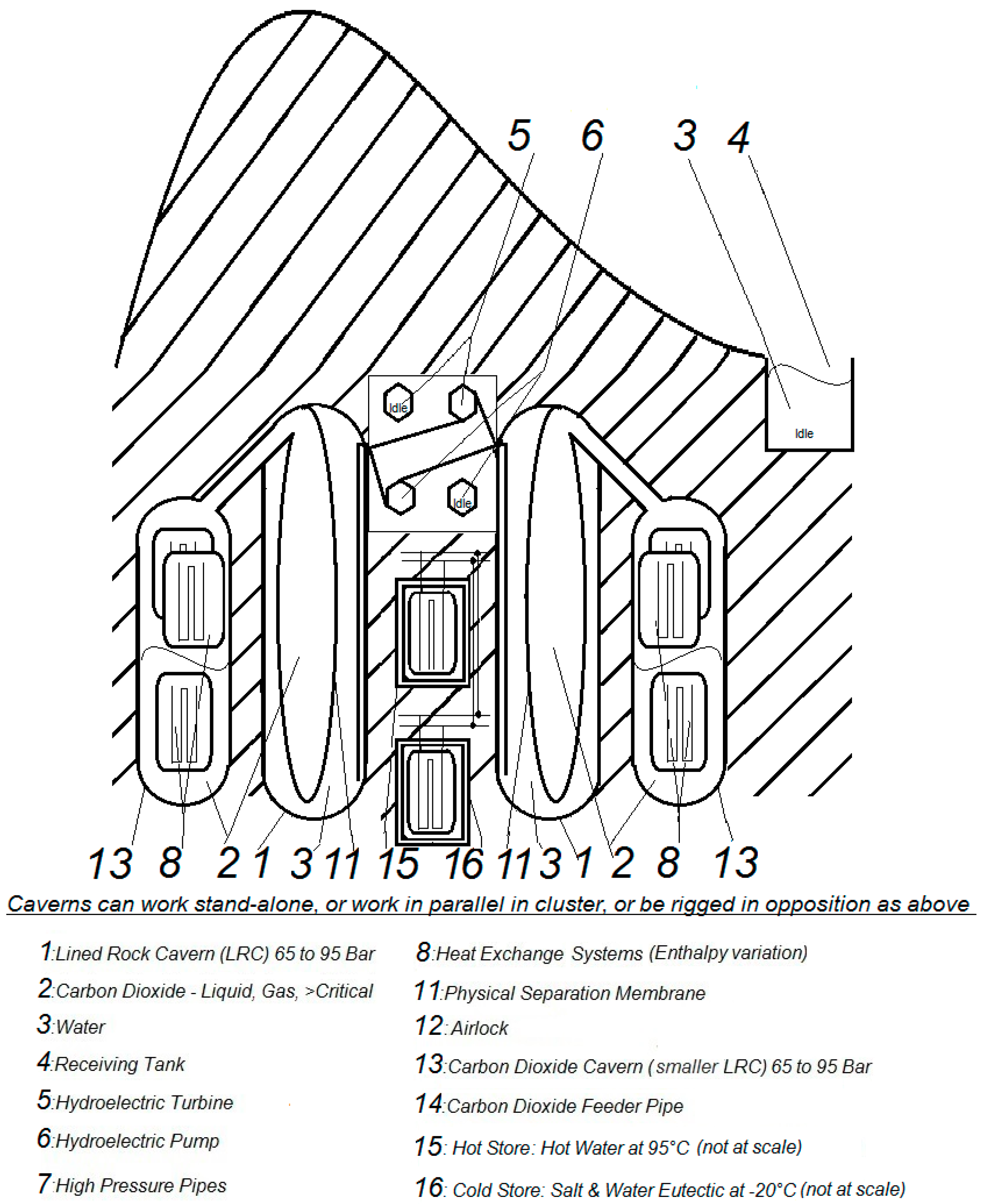
Whenever the Cold Store, due to design or to temporary dysfunction, is of temperature significantly higher than −20 °C or when the Cold Store is just replaced by the ambient environment as it often happens in PTES, the favourite operative configuration would be to rig two caverns A and B in opposition, communicating by the mean of hydro-water and by the mean of either one single pump set when charging in heat-pump mode or of one single turbine set when discharging in thermal engine mode. Thus, the operation of heat-pump and of thermal engine by two caverns rigged in opposition avoids the detrimental back-work ratio of having to repeatedly spend mechanical work to reintroduce hydro-water at mid pressure inside the colder cavern A or B due to the insufficiently low temperature of the Cold Store. In such a configuration of caverns in opposition, illustrated in Figure 10, receiving ponds are left unused/idle.
As one can figure-out from the Pressure-Enthalpy diagram in Figure 9, there is a much heavier exchange of heat happening both ways than the 95 °C heat required from the Hot Store or than the −20 °C heat extracted by the Cold Store. Therefore, as with every other PTES, efficient regeneration of heat is one necessary component of high-level RTE. In heat-pump mode as well as in thermal engine mode, most of this regeneration can be achieved through synchronous exchange of heat between cavern A and cavern B (through CO2-coolant exchangers or through CO2-CO2 exchangers where possible). High-grade heat which cannot be exchanged synchronously needs to be stored in buffer water tanks in order to be used during the next operation.
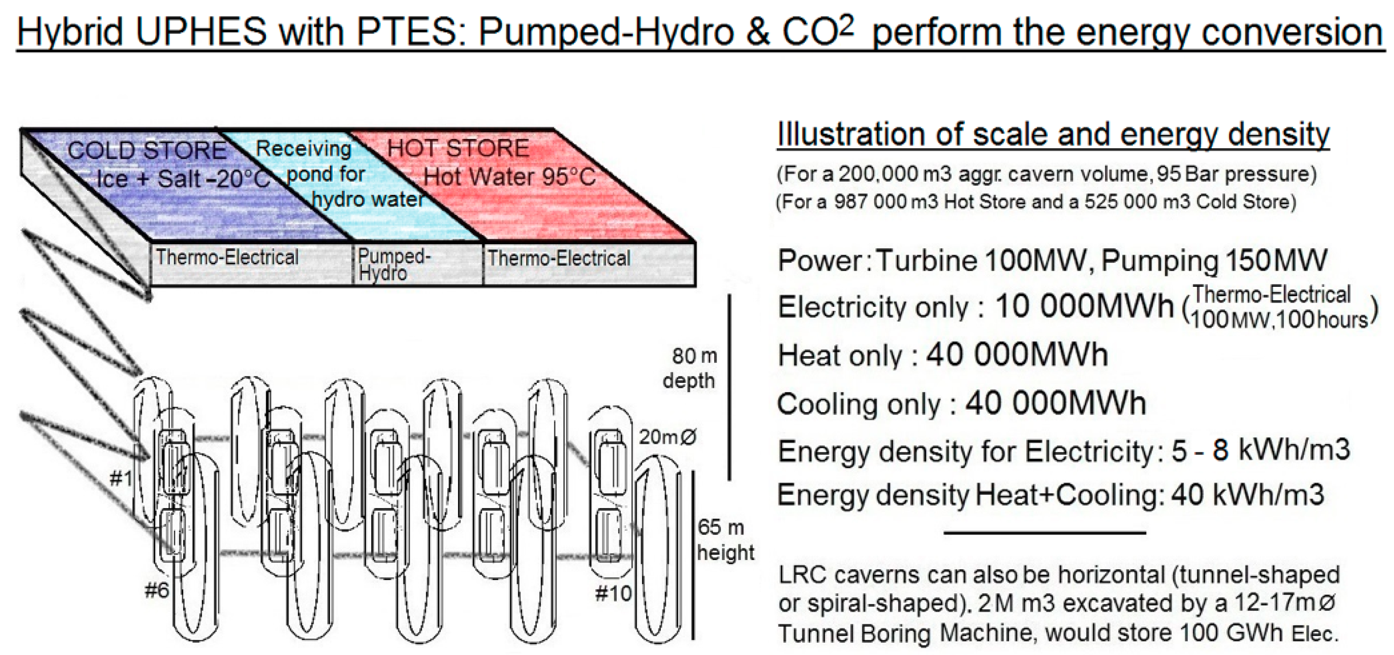
As summary, in this third level of improvement dedicated to long duration storage, UPHES is not the storage per-se but the necessary mechanism of a two-way thermo-electrical energy conversion, slow and as near-reversible as possible, providing hopes that PTES storages could fulfil their long-time promise. As seen above, upon conditions of operations, caverns can be set-up as stand-alone or in parallel (synchronous or asynchronous) or rigged opposed back-to-back. Figure 11 provides some illustrations of scale and some density of energy for the UPHES-PTES storage.
3.3.3. Economic Targets of the UPHES-PTES Hybrid Long-Duration Storage
Target for RTE of our novel storage, at 60%–70% may seem an ambitious figure compared with results currently achieved for pilot plants of other PTES. Besides similar thermal irreversibilities due to imperfect heat exchanges, other existing PTES use high-speed circuits of a working fluid (steam or refrigerant) and need 4 complex turbine or piston machineries working only in gaseous and supercritical phases (1 compressor and 1 expander for the heat-pump mode, 1 compressor and 1 expander for the thermal machine mode). Kim et al. show that, for a traditional vapor compression process bearing a typical back-work-ratio of 36.5% and assuming realistic grid-scale efficiencies of 80% for each machinery, the best RTE which can be attained in theory by high-speed trans-critical circuit PTES is 45% [24]. Dietrich et al. realized in 2016 a model using butane as the working fluid and computed a maximum RTE of 27.3% only [8]. While the Siemens Gamesa company expects a full-scale deployed system to reach in the future round-trip efficiencies of 50%, a RTE of only 25% has been so-far obtained in June 2019 in Hamburg, Germany, after several years of development on a pilot plant of 130 MWh per week [9]. Although there is no reason why large efficient gas compressors and gas turbines could not be developed in a later future, the present lack of high-range RTE in pilot and demonstrator systems is probably the cause impeding the worldwide unfolding of grid-scale PTES. In the favourite configuration of the novel hybrid UPHES-PTES, only 1 operation of a hydro pump and 1 operation of a hydro turbine are needed for a conversion round trip. Thermal irreversibilities of the hybrid UPHES-PTES differs slightly from those of the simpler UPHES as described in paragraph 3.2.4. by the minor fact that hot water and cold water get stored and loose some energy to the ambient environment during storage time (i.e., 3% loss per month). To ascertain the value of RTE in the hybrid mode relatively to the 60%–70% target, is planned for 2020 the construction of an aerial prototype made out of steel vessels, of 35 mm metal thickness, for a total pressurized volume of a few cubic meters.
Thanks to the low cost of atmospheric insulated thermal storages, assessed at 40 USD/ m3 for the Hot Store pit [21] and evaluated at 100 USD/ m3 for the Cold Store ice slurry pit, the expected Capex of a hybrid UPHES-PTES assisted by two large thermal stores can be evaluated, using the same other cost components than in paragraph 3.2.4. above, to a Capex of electricity equal to 2160 USD/kW + 10 USD/kWh (meaning a compounded Capex of 20 USD/kWh only, for a 216 h storage).
Calculations can be counterintuitive because in this configuration the cavern and its receiving pond are not any longer components of energy capacity Capex but, as loci of energy conversion, components of power Capex. Based on the same required power of 100 MW but with an energy capacity increased to 100 h and to 10 GWh, based on two caverns in asynchronous parallel mode achieving a complete cycle in an arbitrary time of 2.5 h, the calculation results in 200,000 m3 of caverns, 200,000 m3 of water receiving pond, 987 000 m3 of Hot Store and 525,000 m3 of Cold Store to achieve the required power and energy capacity.
The power component of Capex is therefore increased, still for 100 MW, of an extra cost of 200,000 m3 X (300 USD + 30 USD), thus 660 USD/kW, raising this power Capex to 2160 USD/kW.
The energy component of Capex needs to be calculated in a table like Table 2 below.
Using the same components of Capex, as a crude estimate of the Capex for the pure supply of heating and cooling, we can simply divide the Capex for electricity by 500%, which bring a Capex of heat and cooling equal to roughly 432 USD/kW Thermal + 2 USD/kWh Thermal (meaning a compounded 4 USD/kWh only, for a 216 h storage).
4. Discussion
A hybrid solution of low Capex (20 USD per kWh of electricity) and of medium-high targeted RTE (60%–70%) is proposed, making use of the reliability and efficiency of pumped-hydro equipment, of the emerging technology of shallow LRC (Lined Rock Cavern) and of the low Capex of large atmospheric thermal stores. More thermodynamic work is needed, by software simulation and small-scale experimentations to precisely evaluate the values of thermal irreversibility at heat exchangers, the possible gradients of temperature of CO2 within the caverns and the Round Trip Efficiency of the system in different storage modes. More work is needed to define the components of the membrane ensuring tightness of CO2 related to hydro-water. Some chemistry work is needed on the possible use of binary/trinary mixtures of CO2 with selected molecules in low molar fraction, in order to optionally displace the critical point of CO2 mixtures according to the different storage modes.
5. Conclusions
Innovative ways to enlarge the contribution of Pumped-Hydro is desirable for the energy transition. In a first work, this paper has studied a CO2 UPHES using a LRC cavern as the place of storage of mechanical energy, concluding to a Capex of pure electricity equalling 1500 USD/kW Elec. + 200 USD/kWh Elec.. Despite being simpler for storages of short and medium term durations, this configuration suffers, for long durations and large-scale energy capacity, from the high cost of cavern excavation and from a weak effect of scale. A second configuration is therefore proposed for long-duration storage, where the CO2 UPHES is actually the conversion subsystem of a larger PTES, leading to a Capex of electricity equalling 2160 USD/kW + 10 USD/kWh, meaning a compounded Capex of 20 USD/kWh only, for a 216 h storage. The RTE of the latter system, devoid of the 4 gas machineries of conventional PTES, is targeted at 60%–70%, subject to the absence of unexpected thermal irreversibilities. Validation by simulation and experimentation are planned in a later stage and are absolutely needed to ascertain a more reliable value of RTE in each storage mode. With the three innovations of using shallow high-pressure LRCs caverns excavated close to storage needs, of using a CO2 piston slowly applying steady pressure on the hydro part of UPHES and of relying on inexpensive Hot Store and Cold Store for the long-duration storage of electrical energy, CO2 UPHES coupled with PTES could become a game-changer by allowing a complete integration of intermittent renewable sources in the energy-mix. Moreover, the paper has shown that, due to an attractive COP of heat displacement expected to reach up to 10 depending on required temperatures, the CO2 UPHES, as well as the UPHES-PTES hybrid storage, could also grant a low LCOS, a low investment (compounded Capex of only 4 USD/kWh thermal, for a 216 h storage) and low-emissions for the faster deployment of solar and wind, deemed to displace fossil fuels in future district heating and cooling networks, as required by cities and by most industrial developments.
6. Patents
Pending Patent: Dispositif hybride de stockage ou de conversion énergétiques, à fluide propulseur liquide, gazeux ou supercritique, filed at INPI, by Pascal Lalanne holder of patent rights, on the 19th of June 2019, with priority date 16th of February 2019 from previous pending patent.
Author Contributions
Conceptualization, P.L.; formal analysis, Pascal Lalanne; writing—original draft preparation, P.L.; writing—review and editing, P.B.; visualization, P.B.
Funding
This research received no external funding.
Conflicts of Interest
The authors declare no conflict of interest.
References
- Ram, M.; Bogdanov, D.; Aghahosseini, A.; Gulagi, A.; Oyewo, A.S.; Child, M.; Caldera, U.; Sadovskaia, K.; Farfan, J.; Barbosa, L.S.N.S.; et al. Global Energy System based on 100% Renewable Energy—Energy Transition in Europe Across Power, Heat, Transport and Desalination Sectors; Study by LUT University and Energy Watch Group; Research Reports 89; Lappeenranta University of Technology: Lappeenranta, Finland, December 2018; ISBN 978-952-335-329-9. ISSN 2243-3376. [Google Scholar]
- International Energy Agency. The Future of Cooling; OECD: Paris, France, 2018. [Google Scholar]
- Cavazzini, G. Solutions for Pumped Hydro Energy Storage Plants. Sci. Trends 2018. [Google Scholar] [CrossRef]
- Tallini, A.; Vallati, A.; Cedola, L. Applications of micro-CAES systems: Energy and economic Analysis. Energy Procedia 2015, 82, 797–804. [Google Scholar] [CrossRef]
- Mercangöz, M.; Hemrle, J.; Kaufmann, L.; Z’Graggen, A.; Ohler, C. Electrothermal energy storage with transcritical CO2 cycles. Energy 2012, 45, 407–415. [Google Scholar] [CrossRef]
- McTigue, J.D.; White, A.J.; Markides, C.N. Parametric studies and optimisation of pumped thermal electricity storage. Appl. Energy 2015, 137, 800–811. [Google Scholar] [CrossRef] [Green Version]
- Georgiou, S.; Shah, N.; Markides, C.N. A thermo-economic analysis and comparison of pumped-thermal and liquid-air electricity storage systems. Appl. Energy. 2018, 226, 1119–1133. [Google Scholar] [CrossRef]
- Dietrich, A.; Dammel, F.; Stephan, P. Exergoeconomic Analysis of a Pumped Heat Electricity Storage System with Concrete Thermal Energy Storage. Int. J. Thermodyn. 2016, 19, 43–51. [Google Scholar] [CrossRef]
- Deepsource. Siemens-Gamesa Electric Thermal Energy Storage. Available online: https://deepresource.wordpress.com/2019/06/17/siemens-gamesa-electric-thermal-energy-storage/ (accessed on 30 September 2019).
- Pujades, E.; Willems, T.; Bodeux, S.; Orban, P.; Dassargues, A. Underground pumped storage hydroelectricity using abandoned works (deep mines or open pits) and the impact on groundwater flow. Hydrogeol. Geol. 2016, 24, 1531–1546. [Google Scholar] [CrossRef] [Green Version]
- SHELL Internationale Research Maatschappij B.V of Netherlands. Storage and Recovery. Patent No. 0196 690, 18 October 1989. [Google Scholar]
- Bi, J.; Jiang, T.; Chen, W.; Ma, X. Research on Storage Capacity of Compressed Air Pumped Hydro Energy Storage Equipment; North China Electric Power University, Beijing, China. Energy Power Eng. 2013, 5, 26–30. [Google Scholar] [CrossRef]
- Odukomaiya, A.; Abu-Heiba, A.; Gluesenkamp, K.R.; Abdelaziz, O.; Jackson, R.K.; Daniel, C.; Graham, S.; Momen, A.M. Thermal analysis of near-isothermal compressed gas energy storage system. Appl. Energy 2016, 179, 948–960. [Google Scholar] [CrossRef]
- Johansson, J. Storage of highly compressed gases in underground Lined Rock Caverns—More than 10 years of experience. In Proceedings of the World Tunnel Congress 2014–Tunnels for a Better Life, Foz do Iguaçu, Brazil, 9–15 May 2014. [Google Scholar]
- Rutqvist, J.; Kim, H.M.; Ryu, D.W.; Synn, J.H.; Song, W.K. Modeling of coupled thermodynamic and geomechanical performance of underground compressed air energy storage in lined rock caverns. Int. J. Rock Mech. Min. Sci. 2012, 52, 71–81. [Google Scholar] [CrossRef]
- Kim, H.M.; Rutqvist, J.; Jeong, J.H.; Choi, B.H.; Ryu, D.W.; Song, W.K. Characterizing Excavation Damaged Zone and Stability of Pressurized Lined Rock Caverns for Underground Compressed Air Energy Storage; Lawrence Berkeley National Laboratory (LBNL): Berkeley, CA, USA, 2014. [Google Scholar] [CrossRef]
- Kim, H.M.; Park, D.; Ryu, D.W.; Song, W.K. Parametric sensitivity analysis of ground uplift above pressurized underground rock caverns. Eng. Geol. 2012, 135, 60–65. [Google Scholar] [CrossRef]
- Perazzelli, P.; Anagnostou, G. Design issues for compressed air energy storage in sealed underground cavities. J. Rock Mech. Geotech. Eng. 2016, 8, 314–328. [Google Scholar] [CrossRef] [Green Version]
- Tunsakul, J.; Jongpradist, P.; Kim, H.M.; Nanakorn, P. Evaluation of rock fracture patterns based on the element-free Galerkin method for stability assessment of a highly pressurized gas storage cavern. Acta Geotech. 2018, 13, 817–832. [Google Scholar] [CrossRef]
- Glamheden, R.; Curtis, P. Excavation of a cavern for high-pressure storage of natural gas. Tunn. Undergr. Space Technol. 2006, 21, 56–67. [Google Scholar] [CrossRef]
- Laine, H.S.; Salpakari, J.; Looney, E.E.; Savin, H.; Peters, I.M.; Buonassisi, T. Meeting global cooling demand withphotovoltaics during the 21st century. R. Soc. Chem. 2019. [Google Scholar] [CrossRef]
- Shwartz, M.; Stanford University. Stanford Scientists Calculate the Carbon Footprint of Grid-Scale Battery Technologies. Available online: https://news.stanford.edu/news/2013/march/store-electric-grid-030513.html (accessed on 30 September 2019).
- Energinet, Danish Energy Agency. Technology Data for Energy storage. First published: November 2018, latest update: February 2019. Available online: http://www.ens.dk (accessed on 30 September 2019).
- Kim, Y.M.; Shin, D.G.; Lee, S.Y.; Favrat, D. Isothermal transcritical CO2 cycles with TES (thermal energy storage) for electricity storage. Energy 2013, 49, 484–501. [Google Scholar] [CrossRef]
Figure 1.
Three models for action of ground against lift-up due to gravity. W is weight, alpha is the angle of friction of the rock mass, usually 30–45 degrees [19].
Figure 1.
Three models for action of ground against lift-up due to gravity. W is weight, alpha is the angle of friction of the rock mass, usually 30–45 degrees [19].

Figure 2.
Computerized value of the safety factor against lift-up related to normalized storage pressure (dimensionless value of gas pressure in cavern divided by rock weight pressure at cavern ceiling) and related to normalized storage depth (dimensionless value of cavern ceiling depth divided by cavern inner radius) [17].

Figure 3.
Vertical plane section of the Skallen gas storage plant, showing one of the 4 caverns [19].
Figure 3.
Vertical plane section of the Skallen gas storage plant, showing one of the 4 caverns [19].

Figure 4.
Different applications of the novel system, for storage of short and medium durations, illustrated on the Enthalpy–Pressure diagram related to CO2.
Figure 4.
Different applications of the novel system, for storage of short and medium durations, illustrated on the Enthalpy–Pressure diagram related to CO2.

Figure 5.
Insulated, atmospheric, thermal pits and thermal tanks, designed for thermocline layers.

Figure 6.
Principles for a PTES (Pumped Thermal Electricity Storage) using a UPHES (Underground Pumped-Hydro Energy Storage) as the locus of energy conversion.
Figure 6.
Principles for a PTES (Pumped Thermal Electricity Storage) using a UPHES (Underground Pumped-Hydro Energy Storage) as the locus of energy conversion.

Figure 7.
Main components of the hybrid UPHES-PTES for long-duration storage (here in stand-alone configuration and with a smaller pressurized cavern dedicated to CO2). UPHES for storage of short and medium duration uses the same components, except for the absence of the two large thermal stores.
Figure 7.
Main components of the hybrid UPHES-PTES for long-duration storage (here in stand-alone configuration and with a smaller pressurized cavern dedicated to CO2). UPHES for storage of short and medium duration uses the same components, except for the absence of the two large thermal stores.

Figure 8.
Main components of the hybrid UPHES-PTES for long-duration storage (here in stand-alone configuration and without the smaller pressurized cavern dedicated to CO2). UPHES for storage of short and medium duration uses the same components, except for the absence of the two large thermal stores.

Figure 9.
Operation of hybrid UPHES-PTES for long-duration storage, illustrated on the Pressure-Enthalpy diagram related to CO2.
Figure 9.
Operation of hybrid UPHES-PTES for long-duration storage, illustrated on the Pressure-Enthalpy diagram related to CO2.

Figure 10.
UPHES-PTES for long-duration storage, rigged with two caverns in opposition. A clarification must be made regarding the fact that in the hybrid UPHES-PTES mode, campaigns of electricity charging and campaigns of electricity discharging are usually relatively long in time (5–500 h). Contrary to modes of shorter duration storages described in paragraphs 3.2.1. and 3.2.2 above, each of these charging or discharging campaigns involves several successive expansions plus contractions of CO2 as well as several successive return trips of hydro-water in and out of the caverns. For calculation of the storage Capex in the hybrid mode, although software simulation and actual experimentation are needed to assess the optimal speed of CO2-water interface displacement, a preliminary value of 2.5 h has been selected as the minimal value for the duration of a return trip of hydro-water.

Figure 11.
Illustrations of scale and of energy density for the UPHES-PTES storage.


Table 1.
Capex of Energy Capacity for the UPHES system.
| Component of Energy Capacity | Volume in m3 | Cost in USD/m3 | Cost in USD |
|---|---|---|---|
| LRC cavern (400 MWh @ 1.750 kWh per m3) | 230,000 | 300 | 69,000,000 |
| Receiving pond for Hydro water | 230,000 | 30 | 6,900,000 |
| Total Capex | - | - | 75,900,000 |
| Total with 5% provision for CO2 cost, etc. | - | - | 80,000,000 |
| Total Capex per KWh of energy | - | - | 200 |
Table 2.
Capex of Energy Capacity for the hybrid UPHES-PTES system.
| Components of Energy Capacity | Volume in m3 | Cost in USD/m3 | Cost in USD |
|---|---|---|---|
| Hot Store for 10 GWh Electrical (atmosph.) | 987,000 | 40 | 39,480,000 |
| Cold Store for 10 GWh Electrical (atmosph.) | 525,000 | 100 | 52,500,000 |
| Total Capex | - | - | 91,980,000 |
| Total Capex with 9% ancillary provision | - | - | 100,000,000 |
| Total Capex per KWh of energy | - | - | 10 |
© 2019 by the authors. Licensee MDPI, Basel, Switzerland. This article is an open access article distributed under the terms and conditions of the Creative Commons Attribution (CC BY) license (http://creativecommons.org/licenses/by/4.0/).
Share and Cite
MDPI and ACS Style
Lalanne, P.; Byrne, P. Large-Scale Pumped Thermal Electricity Storages—Converting Energy Using Shallow Lined Rock Caverns, Carbon Dioxide and Underground Pumped-Hydro. Appl. Sci. 2019, 9, 4150. https://doi.org/10.3390/app9194150
AMA Style
Lalanne P, Byrne P. Large-Scale Pumped Thermal Electricity Storages—Converting Energy Using Shallow Lined Rock Caverns, Carbon Dioxide and Underground Pumped-Hydro. Applied Sciences. 2019; 9(19):4150. https://doi.org/10.3390/app9194150
Chicago/Turabian StyleLalanne, Pascal, and Paul Byrne. 2019. "Large-Scale Pumped Thermal Electricity Storages—Converting Energy Using Shallow Lined Rock Caverns, Carbon Dioxide and Underground Pumped-Hydro" Applied Sciences 9, no. 19: 4150. https://doi.org/10.3390/app9194150
Note that from the first issue of 2016, this journal uses article numbers instead of page numbers. See further details here.