Underwater Wireless Communications for Cooperative Robotics with UWSim-NET
by
 , , and
Diego Centelles
1,* ,
,
Antonio Soriano-Asensi
2,
José Vicente Martí
1,
Raúl Marín
1 and
and
Pedro J. Sanz
1 1
Interactive Robotic Systems Lab, Universitat Jaume I, 12071 Castelló de la Plana, Spain
2
Departament d’Informàtica–ETSE, Universitat de València, 46100 Burjassot, Spain
*
Author to whom correspondence should be addressed.
Appl. Sci. 2019, 9(17), 3526; https://doi.org/10.3390/app9173526
Submission received: 4 August 2019
/
Revised: 18 August 2019
/
Accepted: 24 August 2019
/
Published: 28 August 2019
(This article belongs to the Special Issue New Solutions for Robotic Swarms in Sea Operations)
Abstract
:The increasing number of autonomous underwater vehicles (AUVs) cooperating in underwater operations has motivated the use of wireless communications. Their modeling can minimize the impact of their limited performance in real-time robotic interventions. However, robotic frameworks hardly ever consider the communications, and network simulators are not suitable for HIL experiments. In this work, the UWSim-NET is presented, an open source tool to simulate the impact of communications in underwater robotics. It gathers the benefits of NS3 in modeling communication networks with those of the underwater robot simulator (UWSim) and the robot operating system (ROS) in modeling robotic systems. This article also shows the results of three experiments that demonstrate the capabilities of UWSim-NET in modeling radio frequency (RF) and acoustic links in underwater scenarios. It also permits evaluating several MAC protocols such as additive links online Hawaii area (ALOHA), slotted floor acquisition multiple access (S-FAMA) and user defined protocols. A third experiment demonstrated the excellent capabilities of UWSim-NET in conducting hardware in the loop (HIL) experiments.
1. Introduction
Marine environments are not easy scenarios for human activities, especially when the operations have to be performed at depths larger than 50 m. Underwater research is hampered by the requirement of developing waterproof and weight compensated devices, protected against high pressure. Despite these limitations, the range of underwater applications continuously increases. Research on archaeology or marine environment, maintenance and inspection of oil and gas infrastructures, and fish farming are some examples of human activities conducted at sea. Technological advances have enabled the automation of some of these activities, and also the cooperation of several devices in order to conduct complex tasks. The rise of the number of devices employed in underwater activities has motivated intense research in the field of underwater wireless networks to interconnect all these devices.
A current trend in robotic intervention is focused on cooperative applications with multiple remotely operated vehicles (ROV) or I-AUVs (Autonomous Underwater Vehicles for Intervention). For this, some robots conduct a given task while others perform additional activities, such as visual surveying, to provide the operator with visual feedback of the progress of the operation. The communication between the ROVs or autonomous underwater vehicles (AUV) and the operator is usually based on umbilical cables or acoustic transducers. While these approaches are valid in experiments with a small number of vehicles, the participation of more and more robots in underwater interventions require novel solutions. In general, acoustic communications are a good solution for long range transmissions (>1000 m), but having several robots sharing the same acoustic channel might degrade the performance of the communication link. Therefore, alternative solutions based on radio frequency (RF) [1,2,3] are also considered for short range communications between ROVs. The problem with RF is the strong attenuation of electromagnetic signals in marine water, which limits the communication range to 15 m [4]. Visual light communication (VLC) [5,6,7] is another alternative that has a higher range than RF, but requires that the transmitter and the receiver are aligned. The communication link based on VLC is heavily influenced by water turbidity, being hard to operate in dirty water.
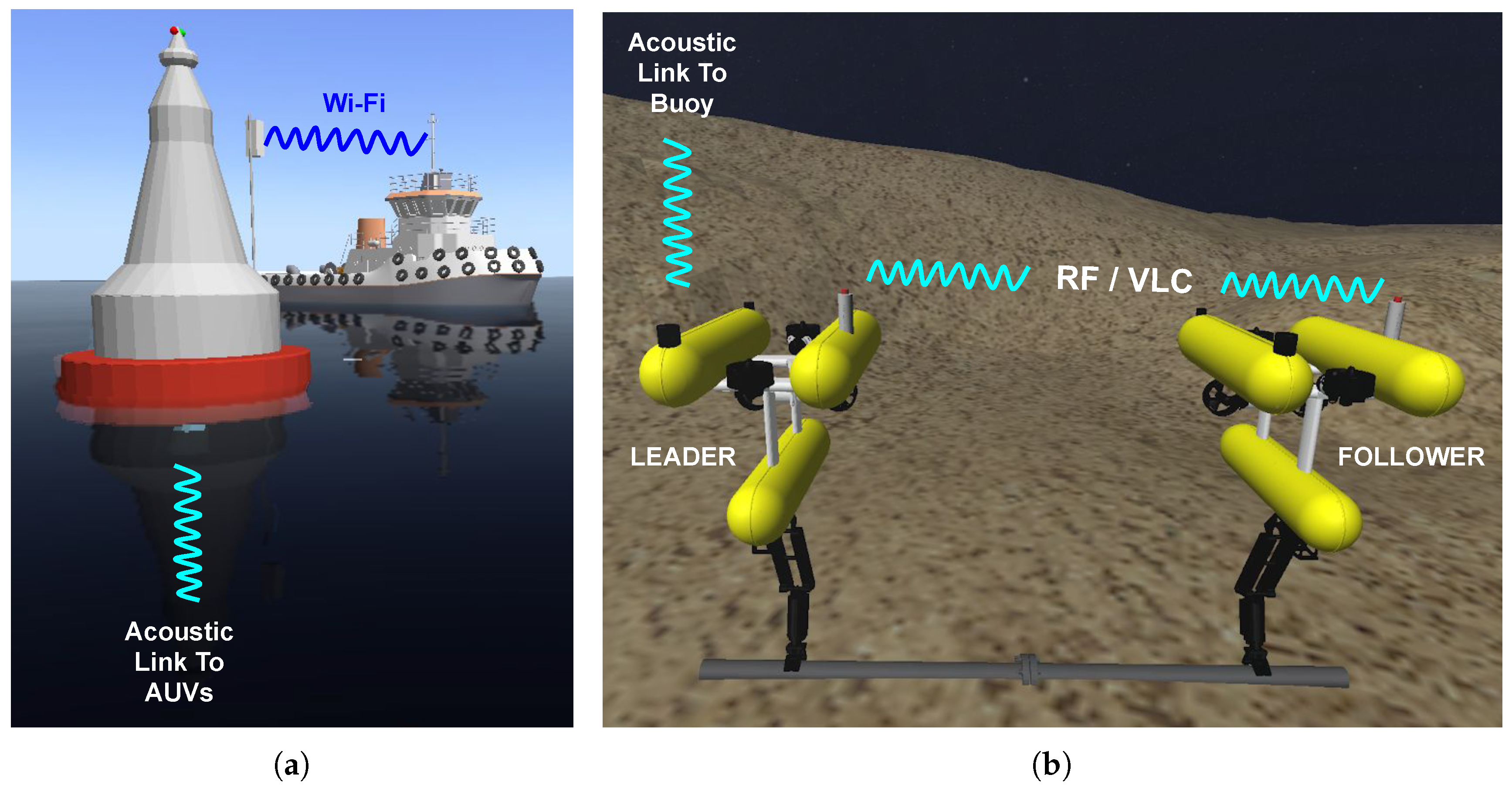
The TWINBOT research project [8] is funded by the Spanish Government and led by some of the authors. It extends previous research on autonomous underwater robotic interventions [9,10]. TWINBOT is aimed at providing experimental evidence about cooperative manipulation with several AUVs. Several wireless approaches for underwater communication will be explored within the TWINBOT project (Figure 1). The communication between the operator on the surface and the AUVs will be based on an umbilical or an acoustic link (Figure 1a). The surface modem will be mounted either on the ship or a buoy via a Wi-Fi connection to the ship. Another goal of the TWINBOT project is to explore the suitability of a VLC or a RF network as possible solutions for communicate the two I-AUV on the seafloor (Figure 1b). The leader AUV will have an acoustic modem for communication with the surface, and will route the commands to the follower via an RF (or VLC) modem. The work presented in this manuscript is the simulation package developed to evaluate the communication technologies to be explored within the TWINBOT project.
The poor performance of wireless technologies at sea has a heavy impact on underwater applications. The modeling of the communications is therefore required to account for their high attenuation, large delay, low range, low bandwidth and low bitrate in underwater scenarios, and the limitations they impose on the application. Several software packages aim at modeling underwater wireless sensor networks (UWSN) [11]. Among them, AquaSim (github: https://github.com/rmartin5/aqua-sim-ng) [12,13] is one of the most popular packages that permits the modeling of acoustic communications in UWSN. It has been implemented as a Network Simulator 3 (NS3) module, and models the majority of network protocols, from physical to routing layers. Among the UWSN protocols implemented in AquaSim [14,15], the experiments in this manuscript consider CS-ALOHA and SFAMA that will be briefly described later in Section 2.2. The underwater acoustic network (UAN) framework is another module available in NS3, which models the physical and link layers of acoustic communications in underwater network scenarios, and also allows modeling AUVs. Its major limitation is the small number of medium access control (MAC) protocols that can be used CW-MAC [16], RC-MAC, and ALOHA. AquaSim permits a higher variety of MAC protocols than UAN. However, they both only permit the modeling of acoustic modems. AquaSim and UAN are excellent tools for modeling UWSN with static nodes. They are able to model moving nodes, but the movement of the nodes is required to be defined in advance, before the simulation starts, which strongly limits them to be considered as simulation tools in cooperative robotics.
Research in underwater environments requires that multiple hardware elements such as experimentation platforms, sensors and modems are properly assembled, which have to work together. Tests at sea are not appropriate for experimentation during the assembly and evaluation stages because of the high number of devices involved. Spatial limitations in the laboratory also complicates the evaluation of the complete system. Hardware-in-the-Loop (HIL) experiments take a key role during the experimentation, since they permit evaluating some of the hardware devices while the remaining devices are modeled by software. The underwater simulator (UWSim), developed by the authors [17], has proven to be an excellent tool in modeling underwater robots, and also as a Human-Robot Interface (HRI) in robotic experimentation.
In this work, we discuss some of the characteristics of UWSim-NET, an extension of UWSim for modeling the behavior of underwater wireless communications for a network of robots. UWSim-NET permits modeling the physical and link layers of an underwater wireless communication system. It also permits evaluating several MAC protocols and to freely modify the position of the nodes during the simulation in order to perform HIL tests. Some experiments conducted with UWSim-NET are also presented in order to show how it can be exploited to benefit the research community in communications for underwater robotic swarms. The remainder of the manuscript is organized as follows. The UWSim-NET is presented in Section 2, which details its architecture and the way the UWSim-NET elements are configured for each simulation. In Section 3, experiments demonstrating the capabilities of the simulator are presented. Firstly, an experiment with two ROVs was performed to demonstrate the modeling of the properties of the physical layer such as the packet loss, collisions, propagation delay and FIFOs. The second experiment aimed to demonstrate the ability to compare different MAC layers in a more complex scenario, such as in the case of the TWINBOT project. The last experiment consisted of the remote control of a team of cooperative robots in HIL (Hardware In the Loop), comparing the results of a teleoperation protocol over two MAC protocols. Finally, Section 4 summarizes the most relevant contributions presented in this manuscript.
2. UWSim-NET
On the one hand, the tools used in robotics allow modeling the kinematics of the robots, but hardly ever account for the communications. On the other hand, there are excellent tools, such as NS3, that permit the modeling of communication networks [13]. However, NS3 simulations require the position of communication nodes to be defined in advance, which hampers the realization of HIL experiments. UWSim [17] has been upgraded to model the behavior of underwater wireless communications for a network of robots. The new extension has been named UWSim-NET (github: https://github.com/uji-ros-pkg/underwater_simulation/tree/uwsimnet-devel) [18].
The main advantage of UWSim-NET is that it is a system integrated in Robotic Operating System (ROS) [19], thus it can not only to simulate the network, but also perform a complete simulation of both the robots and the network in real-time. The movements of the robots and packet flows can be predefined before the start of the simulation as in UAN and AquaSim. UWSim-NET also allows the user to move the devices during the simulation by calling the ROS API as well as permits real traffic sent by the user applications. These two characteristics are essential to conduct HIL experiments in order to test the modems or the user application as well as to model the modems and their impact on the user application without needing to assemble real devices.
The simulation of the communications network in UWSim-NET is based on the real-time event scheduler and other utilities of the NS3 library. It allows simulating both acoustic and custom modems. The modeling of acoustic devices is based on the NS3 module AquaSim NG [13], while RF and VLC devices are simulated as custom modems, based on a high-level statistical model that allows adjusting its bit-rate, intrinsic jitter and delay. Thus, it can reproduce the performance of a real modem. The custom device introduced in UWSim-NET allows modeling half and full duplex links. It also accounts for transmission errors caused by either signal attenuation or packet collisions. The user is able to define the behavior of a generic device by indicating the bitrate, the intrinsic delay, the jitter and the relationship of the bit error rate (BER) with the distance, which can be obtained from experimental measurements.
The architecture of UWSim-NET, shown in Figure 2a, is based on a modular structure. The user application module can be either a real ROV or a simulated ROV. The Generic Link Interface (GLI) is an abstraction layer between the user application and the communication layer. It is aimed at easing the realization of HIL experiments by replacing the modem (Figure 2b) by its model (Figure 2c) when the physical devices are not available. This modular architecture also permits testing the user application even when the modems are not present. AquaSim and UAN allow modeling predefined transmission fluxes between the nodes of the network. This modular architecture of UWSim-NET also allows modeling the impact of the transmission fluxes generated by user applications.
2.1. Generic Link Interface
The GLI is a generic application program interface (API) responsible for the communication between the user application and the communication layer. The purpose of the GLI is to ease the realization of experiments either with a real device or with a modeled device with the UWSim-NET. The interchange of packets between the user application and the UWSim-NET in the GLI is based on POSIX message queues [20]. To exchange messages between the user application and the module in charge of sending the message (either the simulator or the driver of a real device), they are both required to configure the same DCComms identifier.
2.2. DCComms Network Simulator
The modeling of the data link and physical layers of the underwater communication system is in charge of the DCComms Network Simulator module. An accurate modeling of signal propagation (acoustic, RF, VLC, etc.) in sea water requires the characterization of physical parameters such as temperature, salinity, etc. Such a simulation is far from the scope of UWSim-NET purposes. Instead, UWSim-NET pretends to model communication impairments caused signal propagation in physical media as propagation delay and packet loss due to signal attenuation, which depend on the distance between transmission and reception devices. Periodic requests to the transformations tree (TF) system in ROS permit tracking the positions of the devices, and to calculate the distances among them.
- Propagation delay is calculated considering this distance and the propagation speed in the physical medium.
- The likelihood of losing a packet is determined by means of the length of each packet, and a user provided mathematical expression that relates this distance and the BER. Lost packets are randomly discarded according to it.
UWSim-NET also accounts for the communication impairments introduced by real devices as packet collisions and the time the modem requires to process and transmit (receive) each packet, which is modeled by means of an intrinsic delay and a jitter. The communication impairments considered in UWSim-NET are:
- The time the modem requires to process one packet is modeled by the addition of a fixed intrinsic delay and a Gaussian random delay (jitter): Different intrinsic delays can be defined for the transmission and the reception of a packet.
- Transmit and receive delays: The small transmission rates of underwater modems, typically of several kilobits per second (kbps), causes that the times required to transmit or receive a packet being non-negligible. These delays are modeled considering the bitrate of the modem and the length of each data packet.
- Packet collisions: In the case a new packet arrives in a device during the transmission or reception of another packet, both packets are marked as collisions and discarded.
- Transmission FIFO stack: This is where transmission messages are stored temporarily when the device is busy. It has a finite size. Messages arriving when the transmission FIFO is full are thrown away, as occurs in real devices.
- Communication Range: Some modems specify a maximum and minimum distances that guarantee the correct performance of the device. The user can specify these distances and the UWSim-NET will discard all packets sent between two devices whose separation is outside these limits.
The incorporation of NS3 and AquaSim-NG permits UWSim-NET to use the MAC protocols implemented in AquaSim-NG. The two MAC protocols used in the experiments shown in this manuscript are:
- CS-ALOHA is a carrier sense version of the ALOHA MAC protocol. When the transmitter detects that the channel is empty, it starts to send the message. The receiver responds with an acknowledgement (ACK) after a successful read. If the transmitter does not receive the ACK within a predefined time, it considers that that the transmission failed and tries to retransmit the message.
- SFAMA (Slotted Floor Acquisition Multiple Access) divides the time into slots of fixed duration. Slot duration is related with the delay at the maximum communication distance in order to prevent the overlap of RTS messages sent by different ROVs. At the beginning of a slot, the transmitter sends a Request To Send (RTS) message and waits for the Clear To Send (CTS) message sent by the receiver on the reception of CTS. Then, the transmitter starts to send a variable length DATA message. If the transmitter does not receive the CTS message, it assumes that a collision has happened and waits for a number of slots (backoff) before the retransmission of the RTS.
2.3. UWSim-NET XML
All the information required for each experiment is specified by the user in the UWSim-NET XML scene file, whose use is described in detail in [18]. As in UWSim, this file contains the vehicles and their initial positions. The communication channels and the communication devices on board each vehicle are also indicated in the UWSim-NET XML file which includes the following sections:
- NetTracing Script: It is the block of the xml file that allows the user to specify the NetSimTracing class with the callbacks that will handle NS3 events triggered by UWSim-NET, the library with its implementation and the name of the file where the logs will be stored.
- Communication Channels: Each channel, RF, VLC or acoustic, available in the scene will be configured in a CustomCommsChannel block of the xml file. For each channel in the scene, the user is expected to specify a unique identifier and the propagation speed.
- Communication Devices: They are defined in the block of the vehicle, or ROV, and are onboarded. Each vehicle can have as many communication devices as would be required. The user is required to indicate the DCComms identifier that has to coincide with that specified in the user application that communicates with the device via the DCComms API. The user is also expected to provide the channel identifiers the device sends and receives messages, the bitrate, the jitter, the intrinsic delay and the mathematical expression that relates the BER with the distance. The user can also select the medium access control (MAC) protocol to be used by the device.
3. Results
Several experiments were performed to demonstrate the capabilities of UWSim-NET to model the communications of a group of underwater autonomous vehicles. First, an experiment with two robots is presented to illustrate the communication mechanisms modeled in UWSim-NET. A second experiment simulating the teleoperation of two groups of robots is presented to demonstrate the capabilities of UWSim-NET in modeling acoustic and RF communications and several MAC protocols. A final teleoperation experiment combining a real robot and three modeled robots illustrates the possibility to conduct HIL experiments with UWSim-NET.
3.1. Physical Layer
The experiment shown in this section consisted of two robots moving away and approaching each other. The block diagram of this experiment is shown in Figure 2c. It illustrated the packet loss due to attenuation, and packet collisions when both robots try to transmit a message at the same time. This experiment also showed the modeling of the transmission FIFO stacks. Both robots were equipped with Seathooth S100 RF modems [21], by Wireless For Subsea. Packet loss was due to RF attenuation in sea water. The attenuation model used in this experiment was obtained empirically: , being d the distance between devices (in meters). The maximum and minimum ranges of the device were set to 6 m and 0.5 m, respectively.
The motion of the robots during the experiment is shown in Figure 3a. At the beginning of the simulation, the distance between the ROVs was 80 cm. They held the position for 11 s, and then one of the ROVs moved away from the other at a constant speed of 0.25 m/s for 20 s. To ensure that the loss of packets was due to attenuation and to avoid packet collisions, only one ROV transmitted while the other received the packets. The moving ROV returned at the same speed for 5 s and held the position at 4.5 m for 10 s. Then, it moved again towards the fixed robot for 5 s at 0.25 m/s and held the position at 3.3 m. To show the packet collision, the second ROV transmitted during Seconds 37–58 during its return.
Figure 3b,c shows transmitted (blue dots), received (green dots) and lost (black, red and orange dots) packets when two transmission fluxes were considered from node 0 to node 1 and from node 1 to node 0, respectively. Different colors are used to illustrate the packet loss mechanism. The packets dropped because of attenuation are marked in black, while red dots correspond to those that suffered collision. The ones that suffered both attenuation and collision are shown in orange. When the second robot started its transmission at Second 37, when the distance between the ROVs was about 4.5 m both, signal attenuation and collision mechanisms occurred. However, as the second ROV approached, no packets suffered from attenuation, and loses were due to packet collision.
The results shown in Figure 3b illustrate the continuous transmission, and how most of the packets were successfully transmitted. As the second ROV started to transmit (see Figure 3c), it is appreciated in both figures how many packets suffered collisions. The number of successfully transmitted packets was small in both fluxes. As the second ROV stopped sending packets, the situation of the transmission flux, as shown in Figure 3b, returned to the original situation. Both ROVs were configured to transmit at 1500 bps, which is close to the 1800 bps maximum bitrate of the modems. When both ROVs were transmitting, some packets were stored in the transmission FIFO, as can be seen in Figure 3d.
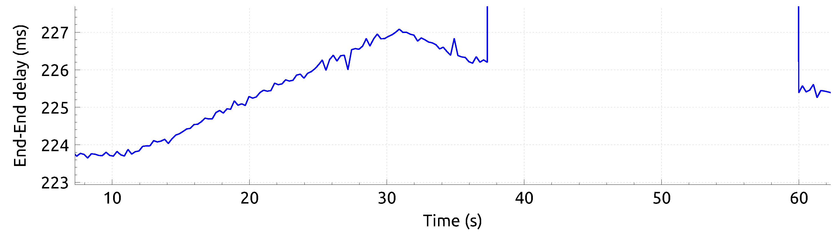
The same experiment shown in Figure 3 was repeated modeling acoustic modems to measure the end-to-end delay, as shown in Figure 4. It accounted for the times required to transmit and receive the packet, and the propagation time. The low bitrate of the modems caused the major contributions to the end-to-end delay to be the transmission and reception times. However, it is appreciated in Figure 4 how the end-to-end delay increased and decreased with the distance between the robots. As it can be seen in Figure 3b, when node 1 started the transmission at 37 s the end-to-end delay rose to ≈430 ms. After the transmission from node 1 stopped, the end-to-end delay values corresponded to those observed at 3.3 m.
3.2. MAC Layer
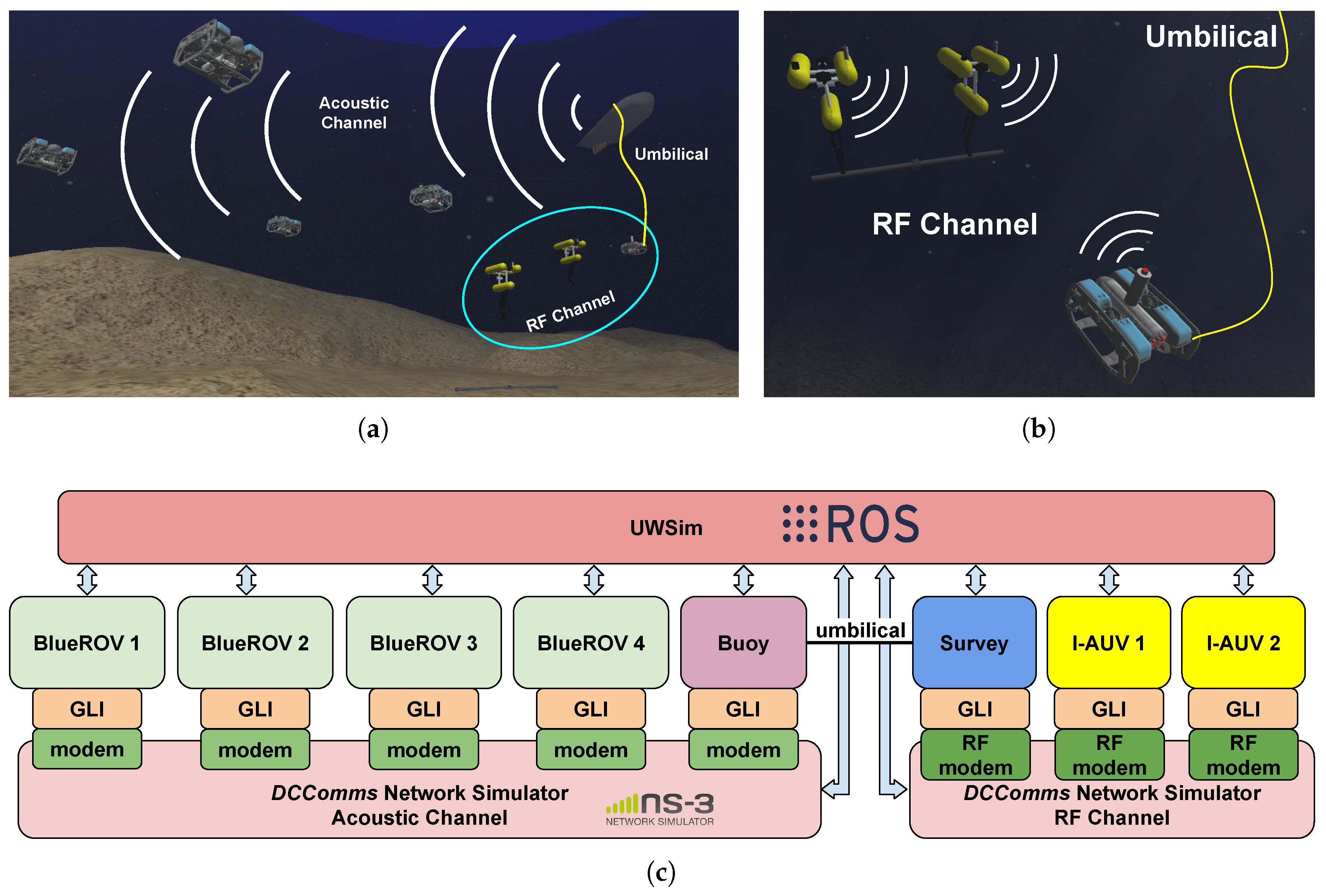
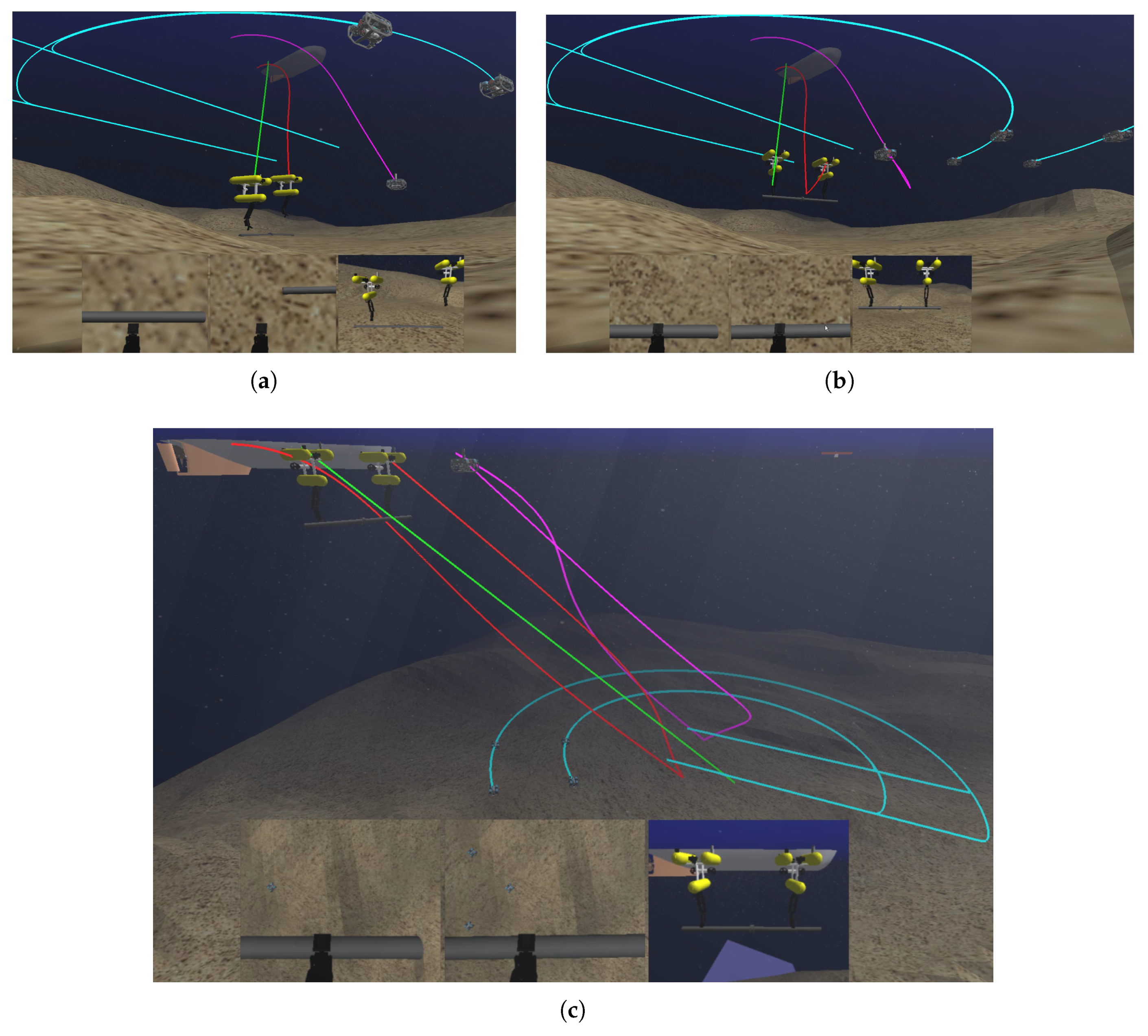
This second experiment demonstrated the ability of UWSim-NET to use different MAC protocols. A scene inspired by the TWINBOT project was used as an example of a real multi-robot scenario (see Figure 5a). This scenario consisted of two Girona500 [22,23] intervention AUV (I-AUV), shown in yellow in Figure 5b, whose objective was to grasp an underwater pipe in a cooperative manner. These two vehicles shared a RF channel to communicate with each other. At the same time, a support vehicle (BlueROV) was connected through an umbilical to a buoy, which was connected with the operator using a WiFi link. The support vehicle tried to follow the trajectory of the I-AUVs in order to implement a communication bridge between the RF channel and the operator. In addition, four extra cooperative AUVs (BlueROV) shown in Figure 5a acted as explorers, making a survey over the seafloor in order to detect other objects of interest for the operator. All explorers shared an acoustic channel to communicate with a buoy in order to send visual data and receive commands from the operator. Seven ROVs were considered in this scenario: the two I-AUV and one BlueROV shared a RF channel and the four BlueROV shared an acoustic channel with the buoy on the surface. The block diagram of the software elements of this experiment is depicted in Figure 5c. The trajectories of each ROV during the experiment are shown in Figure 6.
For this experiment, all communication devices were configured to have a transmission rate of 1.9 kbps and a 1 ms intrinsic delay. Table 1 details the eight data flows defined for this experiment, three for RF communications and five sharing the same acoustic channel. On the one hand, each explorer sent large packets to the surface simulating the transmission of low resolution images. Simultaneously, the buoy sent small broadcast packets with commands destined to the explorers. On the other hand, the remaining three packet flows transmitted between the robots sharing the RF channel. Two of the RF packet flows corresponded to the communication between the two I-AUV, while the third one was the packet flow transmitted from the support vehicle to the I-AUVs.
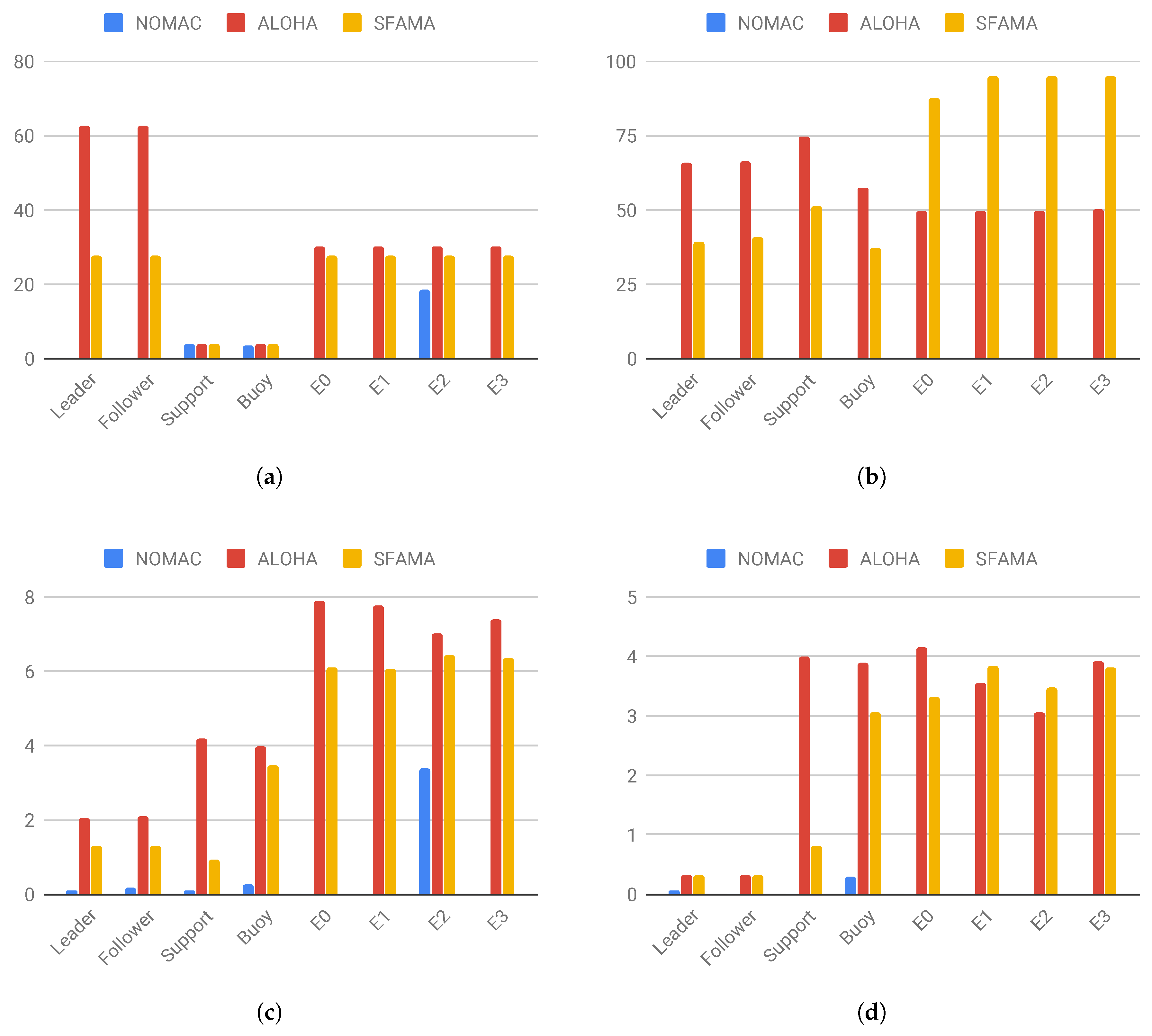
This experiment was repeated considering two MAC protocols: the ALOHA with carrier sensing (CS-ALOHA) and slotted FAMA (S-FAMA). First, the data rates required to send the operator’s commands to the ROVS was established at 32 bps, identified as support and buoy in Table 1. The data flows transmitted by the I-AUV (leader and follower in Table 1) were expected to have a throughput as high as possible, since they were devoted to exchange the pose of leader and follower for the cooperative intervention. The same occurred with the transmissions from the explorers (E0–E3 in Table 1), which were expected to provide the operator with visual feedback of the seafloor, thus to adjust the data rate of each transmission at the maximum value allowed for each protocol. The resulting data rates for each experiment are shown in Table 1. To illustrate the relevance of the MAC layer, the same experiment was done without considering any MAC protocol. The data flows were configured as with the CS-ALOHA.
The performance achieved with each MAC protocol was compared in terms of throughput, efficiency, end-to-end delay and jitter. As expected, the throughput measured after the experiment (see Figure 7a), coincided with the values indicated in Table 1. However, when no MAC protocol was considered, only the data flows transmitted by the support, buoy and E2 succeeded in sending packets. The efficiency is the ratio of bytes successfully received to the total number of transmitted bytes. It is related with the power consumption of the communications system. It is appreciated in Figure 7b that the S-FAMA had a higher efficiency than CS-ALOHA in the acoustic channel, but the opposite occurred with RF channel between the I-AUVs and the support. This behavior might be understood considering the two different sizes of the packets used in each flux: data packets transmitted by leader, follower, support and buoy were 20 bytes long, but the image packets transmitted by the explorers were 400 bytes long. The less overhead of the CS-ALOHA, the smaller number of nodes in the RF channel and the small likelihood of small packets to collide favored the better results observed with the CS-ALOHA. On the contrary, the larger packet sizes and the higher number of nodes favored the better performance of the S-FAMA in the acoustic channel. When no MAC protocol was considered, no positive results were obtained because very few packets were successfully transmitted and the efficiency was near zero.
The end-to-end delay (Figure 7c), and jitter (Figure 7d) are related with the time lapse required to send the information between the ROVs. In general, S-FAMA achieved a lower end-to-end delay than CS-ALOHA (see Figure 7c). The low end-to-end delay achieved when no MAC protocol was used was due to the very low number of successfully transmitted packets. If the transmission succeeded, the packet was delivered immediately, and it had little contribution to the end-to-end delay. Concerning the jitter, comparable results were obtained with both protocols.
3.3. Remote ROV Team Control in HIL
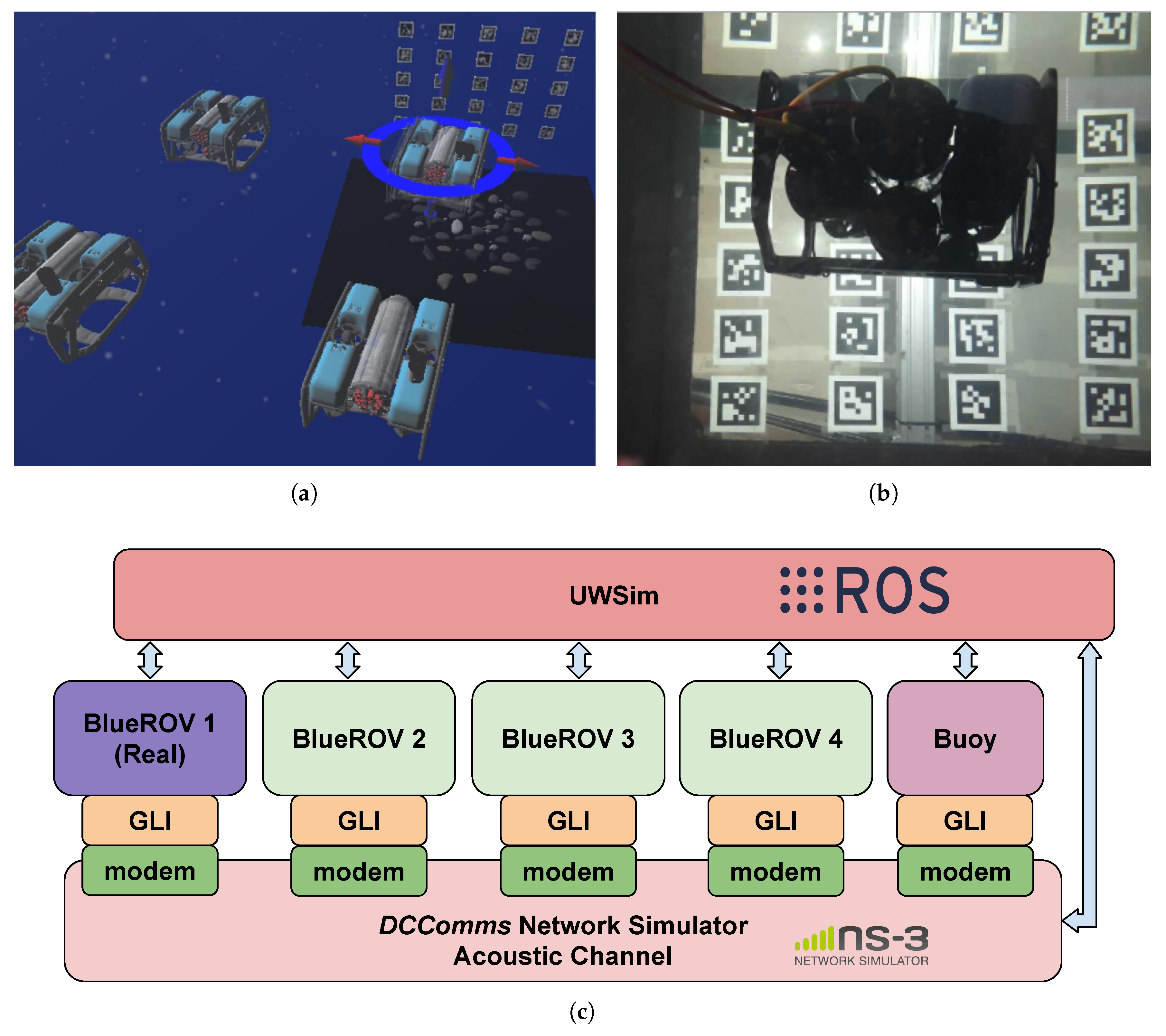
The third experiment presented in this paper demonstrated the capability of UWSim-NET in performing HIL experiments. It corresponded to the four exploration AUVs detailed in Section 3.2. The four AUVs were arranged in a squared formation and the distance between adjacent vehicles was 1.5 m. The leader AUV was replaced by a real BlueROV; it is identified with the marker in Figure 8. The operator sent positioning commands to the leader, and the rest of the AUVs followed the movements of the leader trying to maintain the formation of the AUVs. The block diagram with the software and hardware elements used in this experiment are shown in Figure 8c.
All the AUVs were equipped with acoustic modems; the modems modeled in this experiment are the S2CR 7/17, by Evologics [24]. Despite the umbilical link between the leader and the operator, this communication was simulated with UWSim-NET as an acoustic channel. The transmission fluxes were the same as those indicated in Section 3.2. Since GPS positioning does not work properly in the lab we have at UJI, we developed a positioning feedback based on Aruco markers [25] (see Figure 8).
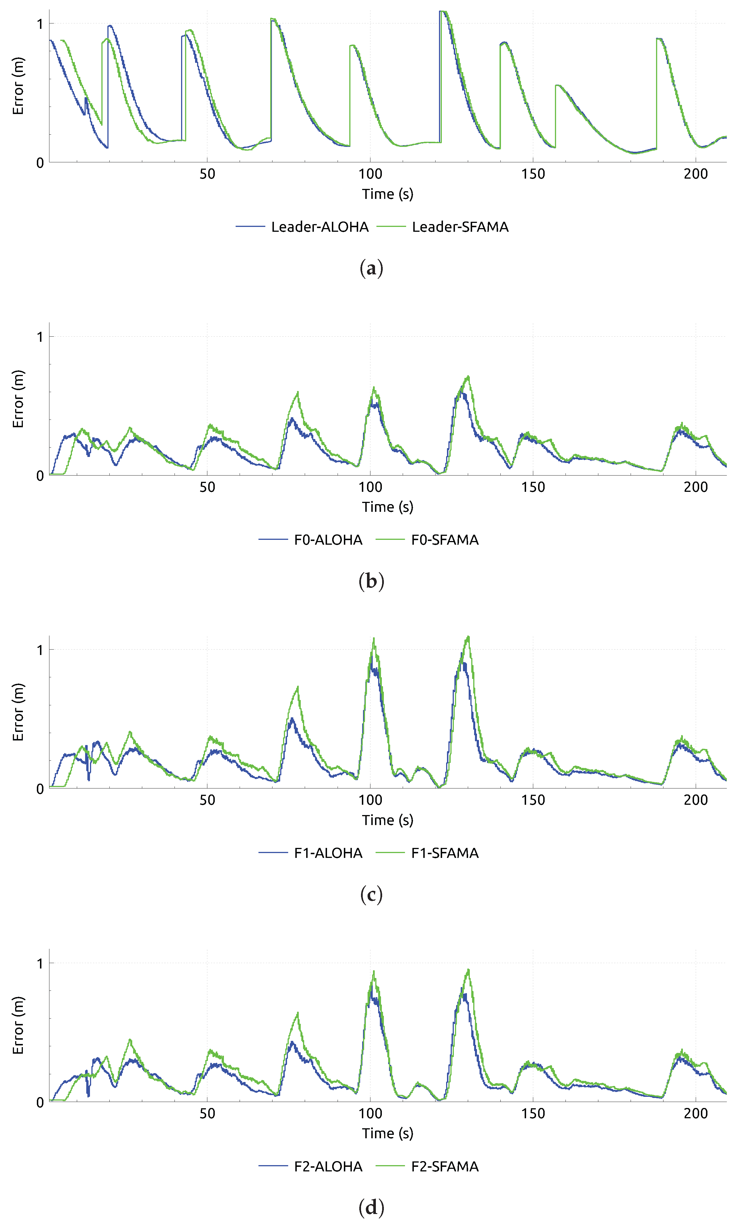
The same experiment was performed considering CS-ALOHA and S-FAMA MAC protocols. Positioning commands were sent from the operator to the leader that moved towards the commanded position, while the other AUVs tried to keep the formation by following the movements of the leader as they noticed them. The comparison among algorithms, as shown in Figure 9, was based on the error distance between real and expected position for each AUV. In the case of the leader, the error was the distance between actual and commanded position (see Figure 9a). A rapid increase of the error is appreciated in Figure 9a every time the leader received a new positioning command. The error for the follower AUVs was the distance between their actual position and their expected position based on the actual position of the leader. As expected, a rapid increase of the error can be appreciated in Figure 9b–d when the leader moved. As appreciated in Figure 8, comparable performance was achieved when CS-ALOHA and S-FAMA MAC protocols were considered.
4. Conclusions
Devices for underwater wireless communications suffer from small bandwidth, high attenuation and large delay. The modeling of these systems might contribute to minimize the impact of their limited performance in cooperative robotic applications. On the one hand, software applications used in robotics such as ROS hardly ever account for the modeling of the communications. On the other hand, network simulators such as NS3 require the user to define in advance all the fluxes and the movements of the nodes during the modeling, which hampers their use in HIL experiments. This manuscript introduces UWSim-NET, an extension of UWSim that permits the modeling of underwater communications for wireless sensors and robots (e.g., AUVs). The modeling of the dynamics of the robots is based on UWSim and ROS, while the communication network is modeled using the NS3. A modular architecture is proposed for UWSim-NET. One of the modules is a Generic Link Interface, which acts as an abstraction layer for the devices. This module facilitates the replacement of real and modeled communication devices, and also permits HIL experimentation.
Three experiments are presented in this article to demonstrate the capabilities of UWSim-NET in modeling communication impairments, allowing RF and acoustic channels, modeling several MAC protocols and performing HIL experiments (see Table 2). The first one modeled an RF and an acoustic link between two robots, and showed the capabilities of UWSim-NET in modeling losses by signal attenuation or packet collisions. The measurement of end-to-end delay and the modeling of the transmission FIFO stack of the modems were also illustrated in this first experiment. The second experiment was the simulation of a search and recovery intervention with autonomous vehicles. The experiment was composed of two groups of three and four AUVs, respectively. The first group of robots, in charge of the intervention, was equipped with RF modems, while the second group was in charge of the search, communicating with acoustic devices. Efficiency, throughput, end-to-end delay and jitter were evaluated when using teh CS-ALOHA and S-FAMA MAC protocols. The results of this experiment demonstrate the relevance of the MAC protocol, and that, depending on the traffic characteristics, a given protocol or another might be preferable. In the third experiment, one of the four BlueROVs modeled in the second experiment was substituted by a real BlueROV. The performance of the supervised remote control was assessed by measuring the distance between expected and real positions of each robot. This experiment demonstrated the capability of UWSim-NET in performing HIL trials.
Author Contributions
Conceptualization, R.M. and P.J.S.; methodology, J.V.M.; software D.C.; validation, R.M.; formal analysis, D.C. and A.S.-A.; investigation, D.C.; resources, J.V.M.; data curation, D.C.; writing—original draft preparation, D.C. and A.S.-A.; writing—review and editing, D.C., A.S.-A. and R.M.; visualization, D.C. and A.S.-A.; supervision, R.M.; project administration, P.J.S.; and funding acquisition, R.M. and P.J.S.
Funding
This research was partially funded by the Spanish Government under under grants BES-2015-073112, DPI2014-57746-C3 (MERBOTS), and DPI2017-86372-C3 (TWINBOT); Generalitat Valenciana under Prometeo program; and Jaume I University under NEPTUNO project.
Conflicts of Interest
The authors declare no conflict of interest.
Abbreviations
The following abbreviations are used in this manuscript:
| API | Application Program Interface |
| AUV | Autonomous Underwater Vehicle |
| BER | Bit Error Rate |
| CS-ALOHA | Carrier Sense—Additive Links Online Hawaii Area |
| CTS | Clear To Send |
| FIFO | First Input First Output |
| GLI | Generic Link Interface |
| GPS | Global Positioning System |
| HIL | Hardware In the Loop |
| HRI | Human Robot Interface |
| I-AUV | Intervention Autonomous Underwater Vehicle |
| MAC | Medium Access Control |
| NS3 | Network Simulator 3 |
| RF | Radio Frequency |
| ROS | Robotic Operating System |
| ROV | Remotely Operated Vehicle |
| RTS | Request To Send |
| S-FAMA | Slotted Floor Acquisition Multiple Access |
| UAN | Underwater Acoustic Network |
| UWSim | UnderWater Simmulator |
| USWim-NET | UnderWater Simulator with Network modeling |
| UWSN | Underwater Wireless Sensor Network |
| VLC | Visual Light Communications |
References
- Che, X.; Wells, I.; Dickers, G.; Kear, P.; Gong, X. Re-Evaluation of RF Electromagnetic Communication in Underwater Sensor Networks. IEEE Commun. Mag. 2010, 48, 143–151. [Google Scholar] [CrossRef]
- Dea, J.; Radosevic, D.; Tran, N.; Chavez, J.; Neuner III, B. Land and Undersea Field Testing of Very Low Frequency RF Antennas and Loop Transceivers; Technical Report; SSC Pacific: San Diego, CA, USA, 2017. [Google Scholar]
- Shaw, A.; Al-Shamma’a, A.; Wylie, S.; Toal, D. Experimental Investigations of Electromagnetic Wave Propagation in Seawater. In Proceedings of the 2006 European Microwave Conference, 36th European, Manchester, UK, 10–15 September 2006; pp. 572–575. [Google Scholar] [CrossRef]
- Wireless for Subsea. Datasheet of Seatooth S100-L Wireless Subsea Controller. Technical Report. Available online: http://www.wfs-tech.com/wp-content/uploads/2017/11/Seatooth-S100-L-Extended-Range-17.11.1.pdf (accessed on 27 August 2019).
- Kaushal, H.; Kaddoum, G. Underwater Optical Wireless Communication. IEEE Access 2016, 4, 1518–1547. [Google Scholar] [CrossRef]
- Farr, N.; Bowen, A.; Ware, J.; Pontbriand, C.; Tivey, M. An integrated, underwater optical /acoustic communications system. In Proceedings of the OCEANS 2010 IEEE, Sydney, NSW, Australia, 4–27 May 2010; pp. 1–6. [Google Scholar] [CrossRef]
- Cossu, G.; Corsini, R.; Khalid, A.; Balestrino, S.; Coppelli, A.; Caiti, A.; Ciaramella, E. Experimental demonstration of high speed underwater visible light communications. In Proceedings of the 2013 2nd International Workshop on Optical Wireless Communications (IWOW), Newcastle upon Tyne, UK, 21–21 October 2013; pp. 11–15. [Google Scholar] [CrossRef]
- IRSLab. TWINBOT Research Project. 2018. Available online: http://www.irs.uji.es/twinbot/ (accessed on 27 August 2019).
- MERBOTS Research Project. Available online: http://www.irs.uji.es/merbots/ (accessed on 27 August 2019).
- Ribas, D.; Ridao, P.; Turetta, A.; Melchiorri, C.; Palli, G.; Fernandez, J.J.; Sanz, P.J. I-AUV Mechatronics Integration for the TRIDENT FP7 Project. IEEE/ASME Trans. Mechatronics 2015, 20, 2583–2592. [Google Scholar] [CrossRef] [Green Version]
- Das, A.P.; Thampi, S.M. Simulation tools for underwater sensor networks: a survey. Netw. Protoc. Algorithms 2017, 8, 41–55. [Google Scholar] [CrossRef]
- Xie, P.; Zhou, Z.; Peng, Z.; Yan, H.; Hu, T.; Cui, J.; Shi, Z.; Fei, Y.; Zhou, S. Aqua-Sim: An NS-2 based simulator for underwater sensor networks. In Proceedings of the OCEANS 2009, Biloxi, MS, USA, 26–29 October 2009; pp. 1–7. [Google Scholar] [CrossRef]
- Martin, R.; Rajasekaran, S.; Peng, Z. Aqua-Sim Next Generation: An NS-3 Based Underwater Sensor Network Simulator. In Proceedings of the International Conference on Underwater Networks & Systems, WUWNET’17, Halifax, NS, Canada, 6–8 November 2017; ACM: New York, NY, USA, 2017; pp. 3:1–3:8. [Google Scholar] [CrossRef]
- Heidemann, J.; Stojanovic, M.; Zorzi, M. Underwater sensor networks: applications, advances and challenges. Philos. Trans. R. Soc. Lond. Math. Phys. Eng. Sci. 2012, 370, 158–175. Available online: http://xxx.lanl.gov/abs/http://rsta.royalsocietypublishing.org/content/370/1958/158.full.pdf (accessed on 27 August 2019). [CrossRef] [PubMed]
- Ayaz, M.; Baig, I.; Abdullah, A.; Faye, I. Review: A Survey on Routing Techniques in Underwater Wireless Sensor Networks. J. Netw. Comput. Appl. 2011, 34, 1908–1927. [Google Scholar] [CrossRef]
- Parrish, N.; Tracy, L.; Roy, S.; Arabshahi, P.; Fox, W. System Design Considerations for Undersea Networks: Link and Multiple Access Protocols. IEEE J. Sel. Areas Commun. 2008, 26, 1720–1730. [Google Scholar] [CrossRef] [Green Version]
- Prats, M.; Pérez, J.; Fernández, J.; Sanz, P. An open source tool for simulation and supervision of underwater intervention missions. In Proceedings of the 2012 IEEE/RSJ International Conference on Intelligent Robots and Systems, Vilamoura, Portugal, 7–12 October 2012; pp. 2577–2582. [Google Scholar] [CrossRef]
- Centelles, D.; Soriano, A.; Martí, J.V.; Marın, R.; Sanz, P.J. UWSim-NET: An open-source framework for experimentation in communications for underwater robotics. In Proceedings of the IEEE Oceans Conference 2019, Marseille, France, 17–20 June 2019. [Google Scholar]
- Quigley, M.; Conley, K.; Gerkey, B.; Faust, J.; Foote, T.; Leibs, J.; Wheeler, R.; Ng, A.Y. ROS: An open-source Robot Operating System. In Proceedings of the ICRA Workshop on Open Source Software, Kobe, Japan, 12 May 2009; Volume 3, p. 5. [Google Scholar]
- Immich, P.K.; Bhagavatula, R.S.; Pendse, D.R. Performance analysis of five interprocess communication mechanisms across UNIX operating systems. J. Syst. Softw. 2003, 68, 27–43. [Google Scholar] [CrossRef]
- Wireless for Subsea. Datasheet of Seatooth S100 Wireless Subsea Controller. Technical Report. Available online: http://www.wfs-tech.com/wp-content/uploads/2017/06/Seatooth-S100-17.-01.-1.pdf (accessed on 27 August 2019).
- Ribas, D.; Palomeras, N.; Ridao, P.; Carreras, M.; Mallios, A. Girona 500 AUV: From Survey to Intervention. Mechatronics IEEE/Asme Trans. 2012, 17, 46–53. [Google Scholar] [CrossRef]
- Palomeras, N.; El-Fakdi, A.; Carreras, M.; Ridao, P. COLA2: A Control Architecture for AUVs. IEEE J. Ocean. Eng. 2012, 37, 695–716. [Google Scholar] [CrossRef]
- Evologics. Datasheet of S2C R 7/17 Underwater Acoustic Modem. Technical Report. Available online: https://evologics.de/acoustic-modem/7-17/r-serie#downloads (accessed on 27 August 2019).
- Garrido-Jurado, S.; Muñoz-Salinas, R.; Madrid-Cuevas, F.; Marín-Jiménez, M. Automatic generation and detection of highly reliable fiducial markers under occlusion. Pattern Recognit. 2014, 47, 2280–2292. [Google Scholar] [CrossRef]
Figure 1.
Illustration of the underwater wireless communication system envisioned for the TWINBOT project: (a) on the surface, an acoustic link from the boat or a buoy will provide communication with the AUVs; and (b) on the seafloor, the leader will incorporate an acoustic modem to communicate with the surface. A short range communication based on RF or VLC will be used between the AUVs on the seafloor.

Figure 2.
UWSim-NET Architecture: (a) block diagram of the UWSim-NET elements; (b) block diagram of an experiment with two ROVs using real modems; and (c) block diagram of an experiment with two ROVs modeling the communications.
Figure 2.
UWSim-NET Architecture: (a) block diagram of the UWSim-NET elements; (b) block diagram of an experiment with two ROVs using real modems; and (c) block diagram of an experiment with two ROVs modeling the communications.

Figure 3.
Collision of packets when two ROVs are transmitting at the same time. Transmitted packets (tx), successfully received packets (rx), packets lost due to attenuation (err(PROP)), packets lost due to collision (err(COL)) and packets that have suffered attenuation and collision (err(MULT)) are presented: (a) distance between the ROVs during the experiment; (b) flux of packets of the ROV that is transmitting continuously; (c) flux of packets of the ROV that starts a transmission while the other ROV is transmitting; and (d) occupation of the transmission FIFO stack.

Figure 4.
End to end delay measured with the model of an acoustic modem.

Figure 5.
Illustration of the scenario of the second experiment. The four BlueROVs in charge of the visual surveying share the acoustic channel with the buoy on the surface. The communication between the two I-AUVs and the survey vehicle is based on an RF network: (a) general view of the scene; (b) details of the RF communication network between the two I-AUVs and the survey AUV with the umbilical to the surface; and (c) block diagram of the elements considered in this second experiment.

Figure 6.
Trajectories followed by the ROVs during the experiment. The trajectories of the explorers are represented in white lines. The lines in yellow and red correspond to the trajectories of the two I-AUVs, and the line in magenta corresponds to the support ROV. Each image corresponds to a different stage of the experiment: (a) approaching; (b) cooperative grasping; and (c) transportation.

Figure 7.
Results for the TWINBOT based scenario without considering any MAC protocol (NOMAC), considering CS-ALOHA MAC protocol (ALOHA) and the S-FAMA MAC protocol (SFAMA), in terms of: (a) throughput (bytes per second); (b) efficiency (%); (c) end-to-end delay (s); and (d) jitter (s).
Figure 7.
Results for the TWINBOT based scenario without considering any MAC protocol (NOMAC), considering CS-ALOHA MAC protocol (ALOHA) and the S-FAMA MAC protocol (SFAMA), in terms of: (a) throughput (bytes per second); (b) efficiency (%); (c) end-to-end delay (s); and (d) jitter (s).

Figure 8.
Cooperative AUV Control in HIL. (a) UWSim visual interface of the HIL experiment with the four robots. The one with the marker is the real BlueROV. The floor of the water tank and the Aruco markers have also been represented in the UWSim visualization. (b) Image of the real BlueROV in the water tank at the IRSLab. (c) Block diagram of the elements used in this experiment.

Figure 9.
Waypoint distance error for each AUV for the CS-ALOHA and S-FAMA MAC protocols. (a) Distance between commanded position and actual position of the leader. Distance between actual position and expected position based on leader’s for: (b) the AUV on the left of the leader; (c) the AUV placed back and left; and (d) the AUV placed behind the leader.


Table 1.
Throughput (Bytes per second) of each packet flow stream during the second experiment.
| RF | Acoustic | |||||||
|---|---|---|---|---|---|---|---|---|
| Leader | Follower | Support | Buoy | E0 | E1 | E2 | E3 | |
| CS-ALOHA | 62.5 | 62.5 | 4 | 4 | 30 | 30 | 30 | 30 |
| S-FAMA | 27.5 | 27.5 | 4 | 4 | 27.5 | 27.5 | 27.5 | 27.5 |
Table 2.
Summary of the main findings of each experiment.
| Experiment | Description | Findings |
|---|---|---|
| Physical Layer | Two moving AUVs sending data at the same time | Demonstration of the correct modeling of end-to-end delay, packet loss, packet collisions and the transmission FIFOs. |
| MAC layer | Cooperative intervention with 4 AUVs sharing an acoustic channel and 3 I-AUVs sharing an RF channel. | Demonstration of the capability of UWSim-NET to model acoustic and RF devices, and the possibility to use different MAC protocols. |
| HIL | Teleoperation of 4 AUVs, one of them being a real BlueROV in a water tank | Demonstration of the capability of UWSim-NET to perform HIL experiments in a real application, in which the positions of the AUVs vary arbitrarily during the experiment. |
© 2019 by the authors. Licensee MDPI, Basel, Switzerland. This article is an open access article distributed under the terms and conditions of the Creative Commons Attribution (CC BY) license (http://creativecommons.org/licenses/by/4.0/).
Share and Cite
MDPI and ACS Style
Centelles, D.; Soriano-Asensi, A.; Martí, J.V.; Marín, R.; Sanz, P.J. Underwater Wireless Communications for Cooperative Robotics with UWSim-NET. Appl. Sci. 2019, 9, 3526. https://doi.org/10.3390/app9173526
AMA Style
Centelles D, Soriano-Asensi A, Martí JV, Marín R, Sanz PJ. Underwater Wireless Communications for Cooperative Robotics with UWSim-NET. Applied Sciences. 2019; 9(17):3526. https://doi.org/10.3390/app9173526
Chicago/Turabian StyleCentelles, Diego, Antonio Soriano-Asensi, José Vicente Martí, Raúl Marín, and Pedro J. Sanz. 2019. "Underwater Wireless Communications for Cooperative Robotics with UWSim-NET" Applied Sciences 9, no. 17: 3526. https://doi.org/10.3390/app9173526
Note that from the first issue of 2016, this journal uses article numbers instead of page numbers. See further details here.